EP3604123B1 - Aircraft folding wing tips with stop pads - Google Patents
Aircraft folding wing tips with stop pads Download PDFInfo
- Publication number
- EP3604123B1 EP3604123B1 EP19188752.0A EP19188752A EP3604123B1 EP 3604123 B1 EP3604123 B1 EP 3604123B1 EP 19188752 A EP19188752 A EP 19188752A EP 3604123 B1 EP3604123 B1 EP 3604123B1
- Authority
- EP
- European Patent Office
- Prior art keywords
- wing
- wing tip
- stop pad
- wear plate
- plate
- Prior art date
- Legal status (The legal status is an assumption and is not a legal conclusion. Google has not performed a legal analysis and makes no representation as to the accuracy of the status listed.)
- Active
Links
Images





Classifications
-
- B—PERFORMING OPERATIONS; TRANSPORTING
- B64—AIRCRAFT; AVIATION; COSMONAUTICS
- B64C—AEROPLANES; HELICOPTERS
- B64C23/00—Influencing air flow over aircraft surfaces, not otherwise provided for
- B64C23/06—Influencing air flow over aircraft surfaces, not otherwise provided for by generating vortices
- B64C23/065—Influencing air flow over aircraft surfaces, not otherwise provided for by generating vortices at the wing tips
-
- B—PERFORMING OPERATIONS; TRANSPORTING
- B64—AIRCRAFT; AVIATION; COSMONAUTICS
- B64C—AEROPLANES; HELICOPTERS
- B64C3/00—Wings
- B64C3/38—Adjustment of complete wings or parts thereof
- B64C3/56—Folding or collapsing to reduce overall dimensions of aircraft
-
- B—PERFORMING OPERATIONS; TRANSPORTING
- B64—AIRCRAFT; AVIATION; COSMONAUTICS
- B64C—AEROPLANES; HELICOPTERS
- B64C3/00—Wings
- B64C3/18—Spars; Ribs; Stringers
- B64C3/187—Ribs
-
- Y—GENERAL TAGGING OF NEW TECHNOLOGICAL DEVELOPMENTS; GENERAL TAGGING OF CROSS-SECTIONAL TECHNOLOGIES SPANNING OVER SEVERAL SECTIONS OF THE IPC; TECHNICAL SUBJECTS COVERED BY FORMER USPC CROSS-REFERENCE ART COLLECTIONS [XRACs] AND DIGESTS
- Y02—TECHNOLOGIES OR APPLICATIONS FOR MITIGATION OR ADAPTATION AGAINST CLIMATE CHANGE
- Y02T—CLIMATE CHANGE MITIGATION TECHNOLOGIES RELATED TO TRANSPORTATION
- Y02T50/00—Aeronautics or air transport
- Y02T50/10—Drag reduction
Definitions
- This disclosure relates generally to aircraft and, more particularly, to stop pads for aircraft folding wing tips.
- wingspans Larger aircraft have longer wingspans, which tend to produce more efficient flight.
- taxiway spacing and gate locations for most airports do not provide adequate spacing to accommodate such large wingspans. Therefore, longer wingspan aircraft typically employ folding wing tips. After landing, the wing tips are folded (upwards, downwards, forward, aft or a combination thereof) to reduce the wingspan of the aircraft.
- Document US 2017/0066521 in accordance with its abstract, states an apparatus and method of a wing fold system that may include a latch assembly rotating an unfixed portion of a wing, with respect to a fixed portion of the wing, between a flight position of the wing and a folded position of the wing.
- a first portion of the wing may hold a rotating portion of the latch assembly.
- a second portion of the wing may hold a secured portion of the latch assembly.
- the rotating portion of the latch assembly may rotate between an open position and a closed position.
- a slot in the rotating portion may receive the secured portion of the latch assembly.
- a securing portion of the rotating portion may secure a secured portion of the latch assembly.
- the latch assembly may prevent rotation of the second portion when the wing may be in the flight position.
- the invention pertains to an aircraft wing as defined in appended independent claim 1.
- the invention also pertains to a method for installing stop pads on an aircraft wing having a folding wing tip moveably coupled to a fixed wing portion about a hinge axis, as defined in appended independent claim 11.
- any part e.g., a layer, film, area, region, or plate
- any part indicates that the referenced part is either in contact with the other part, or that the referenced part is above the other part with one or more intermediate part(s) located therebetween.
- Stating that any part is in contact with another part means that there is no intermediate part between the two parts.
- example stop pads for use on aircraft with folding wing tips.
- the example stop pads are disposed on the wing tip and the fixed inboard portion of the wing and form a contact area between the wing tip and the fixed inboard portion of the wing when the wing tip is in an extended position.
- the example stop pads reduce or eliminate wear and/or damage directly to the wing tip and the inboard portion of the wing.
- ICAO Code E which limits wingspans to less than 65 meters so that aircraft can fit through runways, taxiways, gate areas, etc. Therefore, aircraft with larger wingspans (e.g., greater than 65 meters) can employ folding wing tips, which enable the wingspan of the aircraft to be reduced so that the aircraft can fit within the current airport infrastructure (e.g., parking areas, taxiways, etc.).
- each wing of the aircraft includes an inboard or fixed wing portion (e.g., section) and a movable or non-fixed outboard wing portion, i.e., the wing tip, that is moveably coupled to the fixed wing portion.
- the wing tips are rotatably coupled to the respective fixed wing portions via hinges.
- Each wing tip is moveable (rotatable) between an extended position (sometimes referred to as a deployed position, a flight position, or an unfolded position) in which the wing tip extends generally outward from the fixed wing portion and a folded position (sometimes referred to as a stowed or stored position) in which the wing tip is rotated upward to decrease the overall wing span of the aircraft.
- the aircraft includes folding wing tip actuation systems.
- the actuation systems include one or more actuators located between the fixed wing portions of the wings and the wing tips.
- the wings may include locking mechanisms to lock or secure the wing tips in their extended position during flight.
- the locking mechanisms are disengaged, and the actuators move (e.g., lift, transition, rotate, etc.) the wing tips about their respective hinges from the extended position to the folded position. Similarly, before take-off, the actuators move the wing tips downward to the extended position and the locking mechanisms are activated to lock the wing tips in the extended position.
- the actuators move (e.g., lift, transition, rotate, etc.) the wing tips about their respective hinges from the extended position to the folded position.
- the actuators move the wing tips downward to the extended position and the locking mechanisms are activated to lock the wing tips in the extended position.
- one or more ledges or stops may be provided on the wing tip and the fixed wing portion of the wing.
- the ledges are positioned (e.g., along a same radial arc) to engage each other if the wing tip is rotated beyond the extended position.
- a first stop pad is disposed on and coupled to a ledge (or another structural component) of the fixed wing portion and a second stop pad is disposed on and coupled to a ledge or another structural component) of the wing tip.
- the first and second stop pads engage each other and prevent direct contact between the ledges of the wing tip and the fixed wing portion.
- the wing tip actuator applies a relatively high load (sometimes referred to as preload) on the wing tip that forces the first and second stop pads against each other.
- This relatively high load prevents the wing tip from moving (e.g., bouncing, chattering, etc.) and, thus, prevents the first and second stop pads from moving apart from each other.
- a locking mechanism may be activated to lock the wing tip in the extended position. Then, the preload is removed. While the wing tip is in the extended position, the first and second stop pads remain in contact. In some examples, movement (e.g., slippage) may occur between the stop pads while the wing tip is in the extended position. Over time, this repetitive contact and/or movement between the first and second stop pads may cause the first and/or second stop pads to wear or erode.
- the stop pads are relatively inexpensive and can be replaced much more easily than replacing the entire wing tip or the fixed wing portion. Therefore, rather than allowing the ledges on the wing tip and the fixed wing portion to engage each other, which can potentially cause wear and/or damage over time, the example stop pads are used to absorb the wear and/or damage.
- the two stop pads are positioned such that a contact plane occurring between the two stop pads (when engaged) is coplanar with the hinge axis of the wing tip.
- This contact plane is also perpendicular to a radial arc of the hinge line. This position decreases the amount of shearing or lateral movement between the two pads. Further, because the contact plane is perpendicular to the radial arc of the hinge line, a majority of the force incurred from movement between the wing tip and the fixed wing portion is perpendicular to the stop pads and, thus, is absorbed as compressive forces on the two stop pads.
- the stop pad on the fixed wing portion and the stop pad on the wing tip include wear plates.
- One of the wear plates is harder than the other wear plate, such that the softer (sacrificial) wear plate is the only plate that wears and eventually needs to be replaced.
- the harder wear plate may be constructed of stainless steel and the softer wear plate may be constructed of a copper-nickel-tin alloy.
- the location of the stop pad on the wing tip is more accessible than the location of the stop pad on the fixed wing portion. The stop pad on the wing tip implements the softer (sacrificial) wear plate, which can then be more easily accessed and replaced when worn out.
- the stop pad on the wing tip includes a filler plate that is disposed between the wear plate and the ledge of the wing tip.
- the filler plate may be selected from a plurality of filler plates having different thicknesses. Depending on the desired position (height) of the wear plate relative to the ledge, an appropriate thickness filler plate can be selected.
- the filler plate enables the wear plate to be positioned in a location where, when the wear plates engaged each other during preload (e.g., before take-off, after landing), the wing tip is aligned in a correct position to be engaged or disengaged by the locking mechanism (e.g., receive a pin or lug in a receiving hole).
- the locking mechanism e.g., receive a pin or lug in a receiving hole
- the filler plate is constructed of a frangible material, such as an aluminum-silicon bronze alloy.
- a frangible material is selected that does not yield during normal operating conditions (e.g., from wing bending/deflection occurring during flight, while the wing tip actuator is driving the wing tip downward, etc.), but yields when subjected to a significantly high impact or force outside of the normal operating conditions, such as during a free-fall event.
- a free-fall event occurs when the wing tip free falls from the folded position to the extended position (without controlled movement by the actuator).
- the frangible material of the filler plates yields to distribute the load through plastic deformation, thereby dampening the impact between the two components and, thus, reducing potentially expensive damage to the two components. Therefore, the example stop pads are configured to handle complex structural flight and ground loads.
- FIG. 1 illustrates an example aircraft 100 in which the examples disclosed herein may be implemented.
- the aircraft 100 includes a fuselage 102, a first or left wing 104 coupled to the fuselage 102, and a second or right wing 106 coupled to the fuselage 102.
- the first and second wings 104, 106 carry respective engines 108, 110.
- the first and second wings 104, 106 include wing tips, which may be transitioned from an extended or flight position (as shown in the position in FIG. 1 ) to a stored or folded position to decrease a wingspan 112 of the aircraft 100.
- the first wing 104 includes a first fixed wing portion 114 (e.g., an inboard wing portion) and a first wing tip 116 (e.g., a non-fixed portion, an outboard wing portion).
- the first wing tip 116 is hingeably coupled to the first fixed wing portion 114 and rotates or folds upward about a hinge axis to move between the extended position (the position shown in FIG. 1 ) and the folded position (the position shown in FIG. 3 ).
- the second wing 106 includes a second fixed wing portion 118 and a second wing tip 120, which is hingeably coupled to the second fixed wing portion 118.
- the first and second wing tips 116, 120 may be moved to the folded position.
- the first and second wing tips 116, 120 are actuated by respective first and second wing tip actuators 122, 124 to move or transition the first and second wing tips 116, 120 between the extended position, as shown in FIG. 1 , and the folded position, in which the first and second wing tips 116, 120 are rotated upwards.
- the first and second wing tip actuators 122, 124 may be hydraulic actuators, for example.
- the first and second wing tips 116, 120 are about 3 metres (10 feet) in length.
- the wingspan 112 can be decreased by about 6 metres (20 feet) by folding the first and second wing tips 116, 120.
- the aircraft 100 may comply with the ICAO Code E size limitations, as currently in effect (e.g., under 65 meters), for example.
- the first and second fixed wing portions 114, 118 and/or the first and second wing tips 116, 120 may be longer or shorter, and the first and/or second wing tips 116, 120 may be folded up, down, forward, aft or a combination thereof.
- the first and second wings 104, 106 of the example aircraft 100 carry multiple control surfaces (e.g., aerodynamic surfaces, auxiliary airfoils, etc.) that are located on the first and second wings 104, 106 (e.g., along the leading and trailing edges of the first and second wings 104, 106).
- the control surfaces may be displaced or extended to change the aerodynamic lift of the aircraft 100 during takeoff or landing, for example.
- the control surfaces may include ailerons, flaperons, slats, spoilers, etc.
- FIG. 2 is a top view of the first wing 104 with the first wing tip 116 in the extended position.
- the first wing tip 116 is moveably coupled to the first fixed wing portion 114 about a hinge axis 200.
- the first wing tip 116 can be rotated between the extended position and a folded position, illustrated in FIG. 3 , via the first wing tip actuator 122.
- the first wing tip actuator 122 is a geared rotary actuator (GRA). In other examples, another type of actuator may be implemented.
- the first wing 104 includes a latching or locking mechanism 202 that locks the first wing tip 116 in the extended position.
- the locking mechanism 202 may include an actuator 204 and a pin or lug 206 that is moved into one or more correcting pin or lug hole(s) in the first wing tip 116, which prevents the first wing tip 116 from rotating relative to the first fixed wing portion 114.
- the lug 206 is moveable along a latch axis 208. When the lug 206 is released or retracted, the first wing tip 116 can be rotated between the extended position and the folded position.
- the actuator 204 moves multiple lugs along the latch axis 208. In other examples, multiple actuators may be provided to move respective lugs.
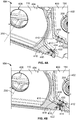
- FIGS. 4A and 4B are perspective cross-sectional views of the first wing 104 taken along line A-A from FIG. 2 .
- FIG. 4A shows the first wing tip 104 rotated upward from the extended position about 15°
- FIG. 4B shows the first wing tip 116 in the extended position.
- the first fixed wing portion 114 includes a first rib 400, which is an internal support structure (e.g., a beam).
- the first rib 400 includes a lug opening 402 in which the lug 206 is disposed.
- the first wing tip 116 includes a second rib 404.
- the second rib 404 includes a hinge opening 406 that receives a pin and/or another structure (e.g., a bearing) to form the hinge axis 200.
- the section of the second rib 404 behind the first rib 400 includes a lug opening (which can be seen in FIGS. 8 and 11 ).
- the lug opening in the second rib 404 is aligned with the lug opening 402 in the first rib 400, and the lug 206 may be inserted (e.g., via activation of the actuator 204 ( FIG. 2 )) into the lug opening in the second rib 404 to lock the first wing tip 116 in the extended position.
- the first and second ribs 400, 404 are constructed of aluminum. In other examples, the first and/or second ribs 404 may be constructed of other materials.
- the first rib 400 of the first fixed wing portion 114 includes a first ledge 408, and the second rib 404 of the first wing tip 116 includes a second ledge 410.
- the first and second ledges 408, 410 may also be referred to hard down stops.
- the first and second ledges 408, 410 are positioned to prevent the first wing tip 116 from rotating downward (in the counter-clockwise direction in FIGS. 4A and 4B ) beyond the extended position.
- the example first wing 104 includes example stop pads (which may also be referred to as down stops or hard stop pads) constructed in accordance with the teachings of this disclosure.
- a first stop pad 412 is coupled to the first fixed wing portion 114 and a second stop pad 414 is coupled to the first wing tip 116.
- the first stop pad 412 is disposed on and coupled to a surface 416 of the first ledge 408, and the second stop pad 414 is disposed on and coupled to a surface 418 of the second ledge 410.
- the first stop pad 412 has a first contact surface 420 and second stop pad 414 has a second contact surface 422.
- first and second contact surfaces 420, 422 come into engagement with each other.
- the first and second stop pads 412, 414 prevent direct contact or engagement of the first and second ledges 408, 410. Over time, one or both of the first or second stop pads 412, 414 may become worn and/or damaged.
- the first and second stop pads 412, 414 are relatively small, inexpensive to manufacture, and easily replaceable. Thus, the first and second stop pads 412, 414 reduce more expensive maintenance to the first wing 104 that would otherwise be required if the first and second stop pads 412, 414 were not included.
- the first and second stop pads 412, 414 are also used to properly position or locate the first wing tip 116 in the extended position for alignment with the locking mechanism 202 ( FIG. 2 ). For example, when the first wing tip 116 is moved to the extended position, the first and second stop pads 412, 414 form a stopping point. This stopping point should be configured (based on the heights or thicknesses of the first and second stop pads 412, 414) such that the lug opening (lug opening 800 shown in FIGS. 8 and 11 ) in the second rib 404 of the first wing tip 116 is aligned with the lug 206 along the latch axis 208. Proper alignment reduces or prevents excessive wear of the openings and the lug 206.
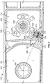
- FIG. 5 is a side cross-sectional view of the first wing 104 taken along line A-A of FIG. 2 .
- the first wing tip 116 is in the extended position and the first and second stop pads 412, 414 are engaged (the same position as shown in FIG. 4B ).
- the first and second stop pads 412, 414 can be coupled to the first fixed wing portion 114 and the first wing tip 116, respectively, via one or more threaded fasteners, as disclosed in further detail herein.
- FIG. 5 shows the first rib 400 of the first fixed wing portion 114 and the latch axis 208 (which extends into the figure).
- FIG. 5 also shows the second rib 404 of the first wing tip 116 and the hinge axis 200 (which extends into the figure) about which the first wing tip 116 rotates.
- the first and second stop pads 412, 414 are disposed within a cavity 501 (e.g., the wing loft) formed between the first wing tip 116 and the first fixed wing portion 114. As such, the first and second stop pads 412, 414 do not extend outward into the atmosphere where they may otherwise cause drag.
- the first stop pad 412 includes a first wear plate 500.
- the first contact surface 420 of the first stop pad 412 corresponds to the top surface of the first wear plate 500.
- the second stop pad 414 includes a second wear plate 502 (e.g., a layer).
- the second contact surface 422 of the second stop pad 414 corresponds to the top surface of the second wear plate 502.
- the second stop pad 414 also includes a filler plate 504, which is disclosed in further detail herein.
- the contact plane 506 formed between the first and second contact surfaces 420, 422 is coplanar with the hinge axis 200.
- the contact plane 506 is also perpendicular to a radial arc 508 of a hinge line (e.g., an arc along which the second stop pad 414 moves).
- first and second stop pads 412, 414 experience compressive loads while the first wing tip actuator 122 is driving the wing tip downward during the locking/unlocking process. Also, when then locking mechanism 202 is engaged, the first and second stop pads 412, 414 can remain engaged and experience compressive forces due to wing bending/deflection. In some examples, due to wing bending/deflection, the first and second stop pads 412, 414 may be moved away from each other.
- the first and second stop pads 412, 414 are relatively rigid and designed to withstand (react to) high compressive forces during normal operating conditions (e.g., during the locking process, from wing deflection during flight, etc.).
- the first and second stop pads 412, 414 are constructed of materials that may perform in the elastic range (and elastically compress) during normal operating loads (but may yield when compression exceeds normal operating levels, as disclosed in further detail below).
- This coplanar arrangement minimizes the amount of shearing (lateral or coplanar) movement between the first and second stop pads 412, 414 and, thus, minimizes wear between the first and second stop pads 412, 414.
- the first and second stop pads 412, 414 can be configured to contact each other along another plane that does not intersect the hinge axis 200.
- the contact plane 506 may be ⁇ 15° coplanar with the hinge axis 200.
- first and second stop pads 412, 414 While most of the loads experienced by the first and second stop pads 412, 414 are compressive forces, some shear forces due to wing bending may occur (e.g., during flight, while the wings bounce during taxiing, etc.). In particular, wing deflection moves the first and second stop pads 412, 414 toward or away from each other and results in a shear force acting in the inboard and outboard directions.
- the first and second contact surface 420, 422 are designed to slip (i.e., allow relative movement in the planar direction). Therefore, the first and second wear plates 500, 502 can be constructed of wear resistant materials to reduce the amount of wear that occurs. However, two different materials are chosen to bias the wear to one of the wear plates 500, 502.
- the first wear plate 500 is constructed of a harder material than the second wear plate 502.
- the first wear plate 500 is considered a permanent side and the second wear plate 502 is considered the sacrificial (wearable) side.
- the first wear plate 500 is constructed of stainless steel (e.g., Custom 465 (UNS S46500)), and the second wear plate 502 is constructed of a copper-nickel-tin alloy (e.g., Cu-15Ni-8Sn (UNS 72900)).
- the second wear plate 502 may wear or erode, whereas the first wear plate 500 may incur little or no wear.
- the main cause of wear is from wing bending, which causes shear loads that may cause the first and second wear plates 500, 502 to slide against each other.
- the second stop pad 414 can be replaced.
- the first and/or second stop pads 412, 414 may be constructed of other types of materials.
- the second ledge 410 on the first wing tip 116 is easier to access for maintenance than the first ledge 408 on the first fixed wing portion 114. Therefore, by disposing the softer (sacrificial) wear plate on the second ledge 410, the worn out stop pad can be quickly and easily replaced.
- the first wear plate 500 of the first stop pad 412 can be constructed of the softer (sacrificial) material, such that the second stop pad 412 is the stop pad that wears out and is replaced.
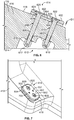
- FIG. 6 is an enlarged cross-sectional view of the second stop pad 414 from FIG. 5
- FIG. 7 is a perspective view of the second stop pad 414 on the second ledge 410.
- the second stop pad 414 includes the second wear plate 502 and the filler plate 504.
- the filler plate 504 has substantially the same size foot print (width and length) as the second wear plate 502.
- the filler plate 504 is disposed on and in contact with the surface 418 of the second ledge 410 of the first wing tip 116
- the second wear plate 502 is disposed on and in contact with the filler plate 504.
- that the filler plate 504 is disposed between the surface 418 of the first wing tip 116 and the second wear plate 502.
- the filler plate 504 is constructed of a frangible material, which yields or non-elastically deforms under high force to absorb peak loads and reduce impact. In some examples, the filler plate 504 is constructed of a material having a yield between 40 to 50 kilopounds per square inch (ksi), i.e. converted into the International System Units about 275.914kPa to 344.893kPa.
- ksi kilopounds per square inch
- the frangible material may be any material that has a yield that is less than the yield of the first and second ribs 400, 404 (e.g., less than 7050 aluminum) but high enough to not yield under normal operating conditions (e.g., from wing deflection during flight, from the force of the first wing tip 116 being driven downward by the first wing tip actuator 122, etc.).
- the filler plate 504 yields before the first and second ribs 400, 404 yield.
- the filler plate 504 is constructed of an aluminum-silicon bronze alloy (e.g., C64200).
- the second wear plate 502 is constructed of a harder material (e.g., copper-nickel-tin alloy) than the filler plate 504.
- the frangible material of the filler plate 504 is designed to yield under loads that are higher than the normal operating load of the first wing tip actuator 122 ( FIGS. 1 and 2 ) and/or any load incurred during normal operation.
- the filler plate 504 may be used to absorb high impact force that may occur between the first wing tip 116 and the first fixed wing portion 114. For example, in the event of a free-fall event of the first wing tip 116, the first and second ledges 408, 410 are pushed together with a relatively high force.
- a free-fall event is an on-ground event where the first wing tip 116 accidently falls to the extended position (as opposed to being moved down at control speed with the first wing tip actuator 122).
- the filler plate 504 yields (e.g., is compressed and squeezed outward from between the second wear plate 502 and the surface 418 of the second ledge 410). This yielding distributes the load and dampens the impact between the first wing tip 116 and the first fixed wing portion 114, thereby reducing or eliminating expensive damage to the surrounding structure.
- the filler plate 504 is constructed of an aluminum-silicon bronze alloy
- the second wear plate 502 is constructed of a copper-nickel-tin alloy
- the first wear plate 500 is constructed of stainless steel. These materials are galvanically compatible with the material of the first and second ribs 400, 404 (e.g., aluminum).
- the filler plate 504, the second wear plate 502, and/or the first wear plate 500 may be constructed of other materials.
- the second stop pad 414 can be coupled to the surface 418 of the second ledge 410 via one or more threaded fasteners.
- the second stop pad 414 is coupled to the surface 418 of the first wing tip 116 via a first bolt 600 and a second bolt 602.
- the first and second bolts 600, 602 extend through respective first and second openings 604, 606 in the second stop pad 414 (through both the second wear plate 502 and the filler plate 504) and through respective first and second openings 608, 610 in the second ledge 410.
- first and second bolts 600, 602 extend into a cavity 612 (e.g., a notch, a groove, etc.) formed in a bottom surface 614 of the first wing tip 116.
- a first nut 616 is coupled to (threaded onto) the first bolt 600 and a second nut 618 is coupled to (threaded onto) the second bolt 602.
- first and second cotter pins 617, 619 may be inserted into the first and second bolts 600, 602 and/or the first and second nuts 616, 618, respectively, to prevent the first and second nuts 616, 618 from being rotated off of the respective first and second bolts 600, 602.
- cotter pins may not be used. Instead, in some examples, relatively taller, stiffer nuts may be use that can accommodate higher pre-loads.
- FIG. 8 is a perspective view of the bottom surface 614 of the first wing tip 116 showing the cavity 612. As shown, the ends of the first and second bolts 602, 602 and the first and second nuts 616, 618 are disposed within the cavity 612, which helps reduce drag along the first wing tip 116. In some examples, the cavity 612 is left uncovered, which enables easy access to the first and second nuts 616, 618 (for easy removal of the second stop pad 412). In other examples, the cavity 612 may be filled with a material (e.g., insulation, a foam filler, etc.) to reduce or eliminate any potential drag caused by the cavity 612. Also shown in FIG. 8 is a lug opening 800 formed in the second rib 404.
- a material e.g., insulation, a foam filler, etc.
- the lug 206 ( FIG. 2 ) may be inserted into the lug opening 800 to lock the first wing tip 116 in the extended position and prevent the first wing tip 116 from rotating.
- the first and second bolts 600, 602 have respective first and second heads 620, 622.
- the first and second heads 620, 622 are tapered.
- the first and second bolts 600, 622 may have differently shaped heads.
- the first and second heads 620, 622 are countersunk into the second stop pad 414. In particular, as shown in FIG.
- the first opening 604 includes a first tapered portion 624 in the second wear plate 502 that receives the first head 620 of the first bolt 600
- the second opening 606 includes a second tapered portion 626 that receives the second head 622 of the second bolt 602.
- the first and second tapered portions 624, 626 are sized such that the tops of the first and second heads 620, 622 are countersunk below the second contact surface 422 (i.e., the top surface) of the second wear plate 502.
- the first and second heads 620, 622 are countersunk a depth of D1.
- the first and second heads 620, 622 are not engaged (unless the second wear plate 502 is worn down a depth of more than D1).
- one or more wear indicators may be provided to indicate an amount of wear that has occurred to the second wear plate 502.
- one or more features are formed in the second contact surface 422 to indicate an amount of wear to the second wear plate 502.
- the second wear plate 502 includes a first dimple 700 (e.g., an indent, a recess, a groove, etc.) and a second dimple 702 formed in the second contact surface 422. As the second wear plate 502 wears or erodes, the depth of the first and second dimples 700, 702 decreases. This can serve as an indicator of the amount of wear to a technician.
- the first and second dimples 700, 702 may know to replace the second wear plate 502 and/or the entire second stop pad 414.
- the first and second dimples 700, 702 have a depth that is less than D1 (i.e., the depth to the first and second heads 620, 622), so that the first and second dimples 700, 702 indicate to replace the second wear plate 502 before the first and second heads 620, 622 begin to protrude.
- first and second dimples 700, 702 are spaced apart from each other and disposed between the first and second bolts 600, 602.
- first and/or second dimples 700, 702 may be disposed in other locations on the second contact surface 422 of the second wear plate 502.
- the second wear plate 502 may include more or fewer dimples.
- only one dimple e.g., the first dimple 700
- other types of wear indicators may be used in addition to or as an alternative to the first and second dimples 700, 702, such as a pin extending upward, a color changing material, etc.
- first and second contact surfaces 420, 422 are designed to slip, thereby allowing relative movement in the contact plane 506 ( FIG. 5 ) as the force (that is normal to the surface) overcomes the static friction.
- the first and second bolts 600, 602 may be implemented as highly pre-loaded (high strength) fasteners (e.g., Inconel fastener type BACB31G). Further, the first and second bolts 600, 602 may be torqued down relatively tightly.
- the compression force exerted by the first and second bolts 600, 602 tightly clamps the second wear plate 502 and the filler plate 504 to the surface 418 to prevent the second wear plate 502 and the filler plate 504 from sliding (slipping) relative to each other. As such, the second wear plate 502 and the filler plate 504 remain rigidly clamped during operation. Further, by highly pre-loading the first and second bolts 600, 602, the first and second bolts 600, 602 do not experience as much (if any) of the effects from relatively lower fatigue loads. Moreover, high durability can be achieved through high pre-loading rather than requiring match drilled openings.
- first and second openings 608, 610 are toleranced such that they can be drilled separately, rather than using a more expensive and complex match drilling process.
- the high pre-loading of the first and second bolts 600, 602 ensures the second stop pad 414 remains in place even though the tolerance of the openings 608, 610 may be looser. This ensures the second stop pad 414 can be easily replaced and reduces the overall manufacturing costs.
- using two bolts helps to prevent rotation and/or lateral movement of the second stop pad 414 relative the surface 418.
- only one bolt may be utilized (e.g., only the first bolt 600).
- more than two bolts may be utilized.
- the second stop pad 414 can be coupled to the first wing tip 116 via one or more other chemical and/or mechanical fastening mechanisms (e.g., one or more screws, an adhesive, welding, etc.).
- the filler plate 504 is selected from a plurality of different filler plates having different thickness (e.g., 0.065 inches (in), 0.070in, 0.075in, etc., i.e. converted into the International System Units about 0,1651 cm, 0,1778 cm, 0,1905 cm) depending on a desired position or location of the second wear plate 502. For example, to position the second wear plate 502 closer to the surface 418, a thinner filler plate can be selected, whereas to position the second wear plate 502 further from the surface 418, a thicker filler plate can be selected. The position of the second wear plate 502 affects the location of the contact plane 506 ( FIG.
- first wing tip 116 affects the position of the first wing tip 116 in the extended position.
- An appropriate filler plate may be selected that results in first wing tip 116 being in a position where the lug opening 800 ( FIG. 8 ) is aligned (i.e., coaxial) with the lug 206 when the first wing tip 116 is in the extended position (e.g., and while being driven downward by the first wing tip actuator 122) during the locking/unlocking process.
- the extended position of the first wing tip 116 can be easily adjusted by replacing the filler plate with another filler plate having a different thickness.
- the manufacturing tolerances of the positions of the first and second ledges 408, 410 can be increased (because selection of a filler plate can be easily used to affect the position of the first wing tip 116), which results in decreased manufacturing costs.
- using an adjustable filler plate enables the first wing tip 116 to be used on a wing of another aircraft, for example, because a different filler plate may be used to finely adjust the final resting/extended position of the first wing tip 116.
- the thickness of the filler plate 504 can also take into account the amount of plastic deformation experienced during the rigging process (e.g., when the first and second stop pads 412, 414 are initially installed). For example, during rigging, a relatively large load may be applied to the first wing tip 116 that is greater than a typical load experienced during flight. Initially, the first and second contact surfaces 420, 422 may not be completely coplanar. However, upon application of this large load, the filler plate 504 may yield (i.e., plastically deform, compress), which enables the second wear plate 502 to settle in a position where the first and second contact surfaces 420, 422 become coplanar with each other along the hinge axis 200.
- the frangible material of the filler plate 504 continues to yield until a large enough area of contact occurs that overcomes the force applied. At this point, the first and second stop pads 412, 414 are considered coplanar or substantially coplanar (e.g., ⁇ 0.1°).
- the original rectangular cross-section of the filler plate 504 may be formed into a trapezoidal shape (depending on the initial alignment between the first and second wear plates 500, 502).
- the first and second nuts 616, 618 may be re-tightened to re-establish the fastener pre-load (e.g., the elastic compression around the first and second heads 620, 622 of the first and second bolts 600, 602) to account for any loss due to the inelastic yielding of the filler plate 504.
- the fastener pre-load e.g., the elastic compression around the first and second heads 620, 622 of the first and second bolts 600, 602
- this process enables manufacturing to build the parts with looser tolerances.
- the surfaces 416, 418 of the first and second ledges 408, 410 may be mapped, and a hydraulic press may be used to plastically deform the filler plate 504 into the correct thickness and shape.
- the pre-molded filler plate 504 can be coupled to the surface 418 of the second ledge 410 along with the second wear plate 502, which results in the first and second contact surfaces 420, 422 being coplanar with each other.
- FIG. 9 is an enlarged cross-sectional view of the first stop pad 412
- FIG. 10 is a perspective view of the first stop pad 412 on the first ledge 408.
- the first stop pad 412 includes the first wear plate 500.
- the first stop pad 412 in this example does not include a filler plate.
- the first wear plate 500 is disposed on and in contact with the surface 416 of the first ledge 408.
- the first stop pad 412 may include a filler plate similar to the second stop pad 414.
- the first stop pad 412 is coupled to the surface 416 of the first ledge 408 via a first bolt 900 and a second bolt 902.
- the first and second bolts 900, 902 extend through respective first and second openings 904, 906 in the first wear plate 500 and through respective first and second openings 908, 910 in the first ledge 408.
- a first nut 912 is coupled to (threaded onto) the end of the first bolt 900 and a second nut 914 is coupled to (threaded onto) the end of the second bolt 902.
- first and second cotter 913, 915 pins may be inserted into the first and second bolts 900, 902 and/or the first and second nuts 912, 914, respectively, to prevent the first and second nuts 912, 914 from being rotated off of the respective first and second bolts 900, 902.
- cotter pins may not be used. Instead, in some examples, relatively taller, stiffer nuts may be use that can accommodate higher pre-loads.
- the first and second bolts 900, 902 have respective first and second heads 916, 918.
- the first and second heads 916, 918 are tapered.
- the first and second bolts 916, 918 may have differently shaped heads.
- the first and second heads 916, 918 are countersunk into the first wear plate 500.
- the first opening 904 in the first wear plate 500 is tapered to receive the first head 916 of the first bolt 900
- the second opening 906 in the first wear plate 500 is tapered to receive the second head 918 of the second bolt 902.
- the first and second openings 904, 906 are sized such that the tops of the first and second heads 916, 918 are disposed below the first contact surface 420 (i.e., the top surface) of the first wear plate 500.
- the first and second heads 916, 918 are countersunk a depth of D2.
- D2 is the same as D1.
- D2 can be less than D1, because most (if not all) of the wear occurs in the second wear plate 502.
- the first wear plate 500 does not include any dimples for wear indication.
- the first wear plate 500 is constructed of a harder material than the second wear plate 502 ( FIG. 5 ).
- the first wear plate 500 may be constructed of stainless steel, while the second wear plate 502 is constructed of a softer material, such as a copper-nickel-tin alloy. As such, most (if not all) of the wear occurs in the second wear plate 502. Therefore, the first wear plate 500 may not need to be replaced.
- one or more dimples may still be included in the first contact surface 420 in case wear does occur.
- first stop pad 412 can be coupled to the first fixed wing portion 114 via one or more other chemical and/or mechanical fastening mechanisms (e.g., one or more screws, an adhesive, welding, shrink fit, etc.).
- the second stop pad 414 may not include the filler plate 504. Instead, the second wear plate 502 may be coupled directly to the second ledge 410. In some examples, the second wear plate 502 is selected from a plurality of wear plates having varying thickness. In some examples, the second wear plate 502 may be constructed of a frangible material. As a result, the second wear plate 502 may yield under forces outside of normal operating conditions (to reduce damage to the parts of the first wing 104), while still operating to absorb wear during normal operating conditions. Therefore, in some examples, the second wear plate 502 may be implemented without a frangible filler plate.
- the second wear plate may be constructed of a relatively hard material (non-frangible) that may be coupled directly to the second ledge 410. Additionally or alternatively, one or more shims or plates of non-frangible material may disposed between the second wear plate 502 (with or without a frangible filler plate) and the second ledge 410 to adjust the location of the second wear plate 502 relative to the second ledge 410.
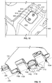
- FIG. 11 is a perspective view of the inboard side of the first wing tip 116.
- the first wing tip 116 is rotatable about the hinge axis 200.
- the first wing tip 116 includes the second rib 404 with the lug opening 800.
- the first wing tip 116 includes three additional ribs 1100, 1102, 1104 with corresponding lug openings 1106, 1108, 1110 to receive one or more pin(s) or lug(s) for locking the first wing tip 116 in the extended position.
- the lug openings 800, 1106, 1108, 1110 are aligned along the latch axis 208.
- the second stop pad 414 is coupled to the second ledge 410, which extends from the second rib 404.
- one or more additional stop pads may be coupled to one or more locations on the first wing tip 116 to contact corresponding stop pads on the first fixed wing portion 114 ( FIG. 1 ).
- a third stop pad 1112 is coupled to a ledge 1114 extending from the rib 1102.
- the third stop pad 1112 may be identical to the second stop pad 414.
- the third stop pad 1112 may include a third wear plate (forming a third contact surface) and a second filler plate.
- FIG. 12 is a perspective view of the outboard side of the first fixed wing portion 114.
- the first stop pad 412 is coupled to the first ledge 408.
- the first stop pad 412 is positioned to be engaged by the second stop pad 414 ( FIG. 11 ) when the first wing tip 116 is in the extended position.
- a fourth stop pad 1200 is coupled to a fourth ledge 1202 on the first fixed wing portion 114.
- the fourth stop pad 1200 may be identical to the first stop pad 412.
- the fourth stop pad 1200 may include a fourth wear plate (forming a fourth contact surface).
- the fourth stop pad 1200 is positioned to be engaged by the third stop pad 1112 ( FIG. 11 ) when the first wing tip 116 is in the extended position. In other words, the third and fourth contact surfaces are to engage each other when the first wing tip 116 is in the extended position.
- FIG. 13 is a bottom view of the first wing 104 in which the first wing tip 116 is in the folded position.
- the ribs 404, 1100, 1102, 1104 extend downward from the bottom side of the first fixed wing portion 114 and are thereby easily accessible by a technician or operator stranding under the first wing 104.
- the first wing tip 116 may be raised to the folded position.
- a technician can walk under the first wing 104 and inspect the condition of the second and third stop pads 414, 1112 on the corresponding ribs 404, 1102. If either of the stop pads 414, 1112 is worn down (e.g., as indicated when the dimples 700, 702 are almost gone or completely gone), the technician can easily replace the corresponding wear plates and/or the entire stop pads.
- first and second stop pads 412, 414 may be utilized.
- more than two pairs of stop pads may be implemented, and the stop pads may be disposed in other locations on the first wing tip 116 and/or the first fixed wing portion 114.
- FIG. 14 is a flowchart illustrating an example method 1400 for installing example stop pads on an aircraft wing having a folding wing tip.
- the example method 1400 may be performed by a human and/or by an automated machine.
- the example method 1400 is described in connection with the first and second stop pads 412, 414 of FIGS. 4A-13 .
- the example method 1400 comprises coupling a first stop pad 412 to the fixed wing portion 114, wherein the first stop pad 412 has a first contact surface 420.
- the example method further comprises coupling a second stop pad 414 to the wing tip 116, wherein the second stop pad 116 has a second contact surface 422 and wherein the first and second contact surfaces 420, 422 are configured to engage each other when the wing tip 116 is in the extended position. Further, in this position a contact plane 506 between the first and second contact surfaces 420, 422 is defined.
- the example method may comprise disposing the first stop pad 412 and the second stop pad 414 so that the contact plane 506 is coplanar with the hinge axis 200.
- example blocks in FIG. 14 can be carried out independently from any preceding steps, e.g. independently from the foregoing step of disposing the first stop pad 412 and the second stop pad 414 so that the contact plane 506 is coplanar with the hinge axis 200. Furthermore, any of the example blocks in FIG. 14 can be rearranged, combined, omitted, replaced, or repeated, insofar as falls within the scope of the appended claims.
- the first wear plate 500 of the first stop pad 412 is disposed on the surface 416 of the first fixed wing portion 114 of the first wing 104.
- the first wear plate 500 is coupled to the surface 418 via one or more fasteners.
- the first and second bolts 900, 902 may be used to couple the first wear plate 500 to the surface 416 of the first ledge 408.
- the first and second bolts 900, 902 may be inserted through the respective first and second openings 904, 906 in the first wear plate 500 and through the respective first and second openings 908, 910 in the first ledge 408.
- first and second nuts 912, 914 may be coupled to (threaded onto) the respective first and second bolts 900, 902.
- the first wear plate 500 may be coupled to the surface 416 via another mechanical and/or chemical fastening technique.
- the first wear plate 500 may be shrink-fit to the surface 416 of the first ledge 408.
- one or more shims or plates may be disposed between the first wear plate 500 and the first ledge 408 to adjust the location of the first wear plate 500 relative to the first ledge 408.
- the filler plate 504 for the second stop pad 414 is selected based on a desired position of the second wear plate 502 (which defines the position of the first wing tip 116 in the extended position).
- the filler plate 504 may be selected from a plurality of fillers plates having different thicknesses.
- a thicker filler plate 504 may be selected, but may be elastically deformed (reduced in thickness) during the rigging process.
- only one thickness frangible filler plate is offered (e.g., a minimum thickness filler plate that yields).
- a plate or shim (constructed of a non-frangible material) is selected from a plurality of shims having different thickness.
- the shim may be disposed between the filler plate and the second wear plate 502 and/or between the filler plate and the surface 418.
- the combination of the selected shim and the filler plate may similarly be used to position the second wear plate 502 from the second ledge 410. Additionally or alternatively, multiple shims may be used.
- the filler plate 504 is disposed on the surface 418 of the first wing tip 116.
- the second wear plate 502 is disposed on the filler plate 504 (which is disposed on the surface 418).
- the second wear plate 502 and the filler plate 504 may be coupled to each other first, and then may be disposed on the surface 418 as a unit.
- the second wear plate 502 and the filler plate 504 are coupled to the surface 418 via one or more fasteners.
- the first and second bolts 600, 602 may be used to couple the second wear plate 502 and the filler plate 504 to the surface 416 of the second ledge 410.
- the first and second bolts 600, 602 may be inserted through the respective first and second openings 604, 606 in the second wear plate 502 and the filler plate 504 and through the respective first and second openings 608, 610 in the second ledge 410.
- the first and second nuts 616, 618 may be coupled to (threaded onto) the respective first and second bolts 600, 602.
- the first wing tip actuator 122 may be activated to apply relatively large load (e.g., a load that is larger than any load exhibited during normal operation) to the first wing tip 116 that pushes the first and second stop pads 412, 414 together, which causes the filler plate 504 to yield and enables the first and second wear plates 500, 502 to become coplanar. Then, the first and second nuts 616, 618 may be tightened down to clamp the second wear plate 502 and the filler plate 504 in this rigid state. In examples not forming part of the claimed invention, the second wear plate 502 and the filler plate 504 may be coupled to the surface 418 via another mechanical and/or chemical fastening technique.
- relatively large load e.g., a load that is larger than any load exhibited during normal operation
- example methods, apparatus, and articles of manufacture have been disclosed that reduce or eliminate wear and/or damage to the structural components of an aircraft wing having a folding wing tip, thereby reducing overall manufacturing and maintenance costs.
- the example stop pads disclosed herein enable the use of high preference folding wing tips with minimal maintenance. Such folding wing tips significantly improve fuel efficiency of an aircraft.
- stop pads can also be used in connection with other types of structures (e.g., non-aircraft structures) where one component is raised and/or lowered to a precise location.
- the stop pads may be used in connection with a bascule bridge (sometimes referred to as a drawbridge).
- the stop pads may be positioned to interface between a movable leaf of the bridge and a fixed side of the bridge.
- the example stop pads can reduce wear and/or damage to the parts of the bridge and/or ensure proper alignment of the leaf and the fixed side of the bridge.
Landscapes
- Engineering & Computer Science (AREA)
- Aviation & Aerospace Engineering (AREA)
- Mechanical Engineering (AREA)
- Toys (AREA)
- Connection Of Plates (AREA)
Description
- This disclosure relates generally to aircraft and, more particularly, to stop pads for aircraft folding wing tips.
- Larger aircraft have longer wingspans, which tend to produce more efficient flight. However, taxiway spacing and gate locations for most airports do not provide adequate spacing to accommodate such large wingspans. Therefore, longer wingspan aircraft typically employ folding wing tips. After landing, the wing tips are folded (upwards, downwards, forward, aft or a combination thereof) to reduce the wingspan of the aircraft.
- Document
US 2017/0066521 , in accordance with its abstract, states an apparatus and method of a wing fold system that may include a latch assembly rotating an unfixed portion of a wing, with respect to a fixed portion of the wing, between a flight position of the wing and a folded position of the wing. A first portion of the wing may hold a rotating portion of the latch assembly. A second portion of the wing may hold a secured portion of the latch assembly. The rotating portion of the latch assembly may rotate between an open position and a closed position. A slot in the rotating portion may receive the secured portion of the latch assembly. A securing portion of the rotating portion may secure a secured portion of the latch assembly. The latch assembly may prevent rotation of the second portion when the wing may be in the flight position. - The invention pertains to an aircraft wing as defined in appended independent claim 1.
- Further aspects of the aircraft wing are defined according to the appended dependent claims.
- The invention also pertains to a method for installing stop pads on an aircraft wing having a folding wing tip moveably coupled to a fixed wing portion about a hinge axis, as defined in appended independent claim 11.
- Further aspects of the method are defined according to the appended dependent claims.
-
-
FIG. 1 illustrates an example aircraft with folding wing tips in which examples disclosed herein may be implemented. -
FIG. 2 is a top view of an example wing of the example aircraft ofFIG. 1 showing an example wing tip. -
FIG. 3 is a perspective view of the example wing fromFIG. 2 in which the example wing tip is in a folded position. -
FIGS. 4A and 4B are perspective cross-sectional views of the example wing ofFIG. 2 taken along line A-A ofFIG. 2 showing a first example stop pad and a second example stop pad constructed in accordance with the teachings of this disclosure. -
FIG. 5 is a side cross-sectional view of the example wing ofFIG. 2 taken along line A-A ofFIG. 2 and showing the first and second example stop pads ofFIGS. 4A and 4B . -
FIG. 6 is an enlarged cross-sectional view of the second example stop pad fromFIG. 5 . -
FIG. 7 is a perspective view of the second example stop pad fromFIGS. 4A-6 . -
FIG. 8 is a bottom view of the example wing tip ofFIG. 2 . -
FIG. 9 is an enlarged cross-sectional view of the first example stop pad fromFIG. 5 . -
FIG. 10 is a perspective view of the first example stop pad fromFIGS. 4A, 4B ,5 , and9 . -
FIG. 11 is a top perspective view of an inboard side of the example wing tip ofFIG. 2 showing a location of the example second stop pad ofFIGS. 4A and 4B . -
FIG. 12 is a bottom perspective view of an outboard side of the example wing ofFIG. 2 showing a location of the example first stop pad ofFIGS. 4A and 4B . -
FIG. 13 is a bottom view of the example wing fromFIG. 2 with the example wing tip in the folded position and showing the location of the example second stop pad ofFIGS. 4A and 4B . -
FIG. 14 is a flowchart representative of an example method of installing one or more stop pads on a wing of an aircraft. - The figures are not to scale. Instead, the thickness of the layers or regions may be reduced or enlarged in the drawings. In general, the same reference numbers will be used throughout the drawing(s) and accompanying written description to refer to the same or like parts. As used in this patent, stating that any part (e.g., a layer, film, area, region, or plate) is in any way on (e.g., positioned on, located on, disposed on, or formed on, etc.) another part, indicates that the referenced part is either in contact with the other part, or that the referenced part is above the other part with one or more intermediate part(s) located therebetween. Stating that any part is in contact with another part means that there is no intermediate part between the two parts.
- Disclosed herein are example stop pads for use on aircraft with folding wing tips. The example stop pads are disposed on the wing tip and the fixed inboard portion of the wing and form a contact area between the wing tip and the fixed inboard portion of the wing when the wing tip is in an extended position. The example stop pads reduce or eliminate wear and/or damage directly to the wing tip and the inboard portion of the wing.
- Before turning to the detailed aspects of the example stop pads, a brief discussion of folding wing tips is provided. It is generally known that longer, lighter and/or thinner wings are more aerodynamically efficient than shorter, heavier wings. Likewise, higher aspect ratio wings produce more efficient flight than lower aspect ratio wings. An aspect ratio of a wing is the ratio of its length to its breadth (chord). Therefore, longer, narrower wings are desirable because they produce more efficient flight (e.g., reduced fuel consumption). However, existing airports present challenges to aircraft having relatively large wingspans (e.g., the distance between the ends or tips of the wings). Airport designs are based on International Civil Aviation Organization (ICAO) Codes A through F as currently in effect, which establish dimensional limits on wingspans, landing gear, width, length, etc. Most airports are designed to accommodate aircraft up to ICAO Code E, which limits wingspans to less than 65 meters so that aircraft can fit through runways, taxiways, gate areas, etc. Therefore, aircraft with larger wingspans (e.g., greater than 65 meters) can employ folding wing tips, which enable the wingspan of the aircraft to be reduced so that the aircraft can fit within the current airport infrastructure (e.g., parking areas, taxiways, etc.).
- In regards to an aircraft having folding wing tips, each wing of the aircraft includes an inboard or fixed wing portion (e.g., section) and a movable or non-fixed outboard wing portion, i.e., the wing tip, that is moveably coupled to the fixed wing portion. In particular, the wing tips are rotatably coupled to the respective fixed wing portions via hinges. Each wing tip is moveable (rotatable) between an extended position (sometimes referred to as a deployed position, a flight position, or an unfolded position) in which the wing tip extends generally outward from the fixed wing portion and a folded position (sometimes referred to as a stowed or stored position) in which the wing tip is rotated upward to decrease the overall wing span of the aircraft. To move or transition the wing tips from the extended position to the folded position (e.g., after landing), the aircraft includes folding wing tip actuation systems. The actuation systems include one or more actuators located between the fixed wing portions of the wings and the wing tips. The wings may include locking mechanisms to lock or secure the wing tips in their extended position during flight. After landing, the locking mechanisms are disengaged, and the actuators move (e.g., lift, transition, rotate, etc.) the wing tips about their respective hinges from the extended position to the folded position. Similarly, before take-off, the actuators move the wing tips downward to the extended position and the locking mechanisms are activated to lock the wing tips in the extended position.
- In some examples, to prevent a wing tip from being rotated downward beyond the extended position and/or to assist in holding the wing tip in the extended position while the locking mechanism is engaged, one or more ledges or stops may be provided on the wing tip and the fixed wing portion of the wing. The ledges are positioned (e.g., along a same radial arc) to engage each other if the wing tip is rotated beyond the extended position.
- Disclosed herein are example stop pads that can be used to reduce or eliminate wear and/or damage to a wing tip and/or a fixed wing portion of an aircraft wing. A first stop pad is disposed on and coupled to a ledge (or another structural component) of the fixed wing portion and a second stop pad is disposed on and coupled to a ledge or another structural component) of the wing tip. When the wing tip is moved to the extended position, the first and second stop pads engage each other and prevent direct contact between the ledges of the wing tip and the fixed wing portion. In some examples, when moving the wing tip into the extended position, the wing tip actuator applies a relatively high load (sometimes referred to as preload) on the wing tip that forces the first and second stop pads against each other. This relatively high load prevents the wing tip from moving (e.g., bouncing, chattering, etc.) and, thus, prevents the first and second stop pads from moving apart from each other. While the load is being applied, a locking mechanism may be activated to lock the wing tip in the extended position. Then, the preload is removed. While the wing tip is in the extended position, the first and second stop pads remain in contact. In some examples, movement (e.g., slippage) may occur between the stop pads while the wing tip is in the extended position. Over time, this repetitive contact and/or movement between the first and second stop pads may cause the first and/or second stop pads to wear or erode. The stop pads are relatively inexpensive and can be replaced much more easily than replacing the entire wing tip or the fixed wing portion. Therefore, rather than allowing the ledges on the wing tip and the fixed wing portion to engage each other, which can potentially cause wear and/or damage over time, the example stop pads are used to absorb the wear and/or damage.
- The two stop pads are positioned such that a contact plane occurring between the two stop pads (when engaged) is coplanar with the hinge axis of the wing tip. This contact plane is also perpendicular to a radial arc of the hinge line. This position decreases the amount of shearing or lateral movement between the two pads. Further, because the contact plane is perpendicular to the radial arc of the hinge line, a majority of the force incurred from movement between the wing tip and the fixed wing portion is perpendicular to the stop pads and, thus, is absorbed as compressive forces on the two stop pads.
- The stop pad on the fixed wing portion and the stop pad on the wing tip include wear plates. One of the wear plates is harder than the other wear plate, such that the softer (sacrificial) wear plate is the only plate that wears and eventually needs to be replaced. For example, the harder wear plate may be constructed of stainless steel and the softer wear plate may be constructed of a copper-nickel-tin alloy. In some examples, the location of the stop pad on the wing tip is more accessible than the location of the stop pad on the fixed wing portion. The stop pad on the wing tip implements the softer (sacrificial) wear plate, which can then be more easily accessed and replaced when worn out.
- In some examples, the stop pad on the wing tip includes a filler plate that is disposed between the wear plate and the ledge of the wing tip. The filler plate may be selected from a plurality of filler plates having different thicknesses. Depending on the desired position (height) of the wear plate relative to the ledge, an appropriate thickness filler plate can be selected. The filler plate enables the wear plate to be positioned in a location where, when the wear plates engaged each other during preload (e.g., before take-off, after landing), the wing tip is aligned in a correct position to be engaged or disengaged by the locking mechanism (e.g., receive a pin or lug in a receiving hole). Thus, the position of the wear plate on the wing tip is easily adjustable.
- In some examples, the filler plate is constructed of a frangible material, such as an aluminum-silicon bronze alloy. A frangible material is selected that does not yield during normal operating conditions (e.g., from wing bending/deflection occurring during flight, while the wing tip actuator is driving the wing tip downward, etc.), but yields when subjected to a significantly high impact or force outside of the normal operating conditions, such as during a free-fall event. A free-fall event occurs when the wing tip free falls from the folded position to the extended position (without controlled movement by the actuator). In such an instance, the frangible material of the filler plates yields to distribute the load through plastic deformation, thereby dampening the impact between the two components and, thus, reducing potentially expensive damage to the two components. Therefore, the example stop pads are configured to handle complex structural flight and ground loads.
-
FIG. 1 illustrates anexample aircraft 100 in which the examples disclosed herein may be implemented. In the illustrated example, theaircraft 100 includes afuselage 102, a first orleft wing 104 coupled to thefuselage 102, and a second orright wing 106 coupled to thefuselage 102. The first andsecond wings respective engines second wings FIG. 1 ) to a stored or folded position to decrease awingspan 112 of theaircraft 100. In particular, thefirst wing 104 includes a first fixed wing portion 114 (e.g., an inboard wing portion) and a first wing tip 116 (e.g., a non-fixed portion, an outboard wing portion). Thefirst wing tip 116 is hingeably coupled to the first fixedwing portion 114 and rotates or folds upward about a hinge axis to move between the extended position (the position shown inFIG. 1 ) and the folded position (the position shown inFIG. 3 ). Similarly, thesecond wing 106 includes a secondfixed wing portion 118 and asecond wing tip 120, which is hingeably coupled to the secondfixed wing portion 118. To reduce the wingspan 112 (e.g., after landing, before taxiing to a gate, etc.), the first andsecond wing tips second wing tips wing tip actuators second wing tips FIG. 1 , and the folded position, in which the first andsecond wing tips wing tip actuators second wing tips wingspan 112 can be decreased by about 6 metres (20 feet) by folding the first andsecond wing tips aircraft 100 may comply with the ICAO Code E size limitations, as currently in effect (e.g., under 65 meters), for example. In other examples, the first and secondfixed wing portions second wing tips second wing tips - In the illustrated example, the first and
second wings example aircraft 100 carry multiple control surfaces (e.g., aerodynamic surfaces, auxiliary airfoils, etc.) that are located on the first andsecond wings 104, 106 (e.g., along the leading and trailing edges of the first andsecond wings 104, 106). The control surfaces may be displaced or extended to change the aerodynamic lift of theaircraft 100 during takeoff or landing, for example. The control surfaces may include ailerons, flaperons, slats, spoilers, etc. - The examples disclosed herein are described below in connection with the
first wing 104. However, it is understood that any of the examples disclosed herein can be similarly applied to thesecond wing 106.FIG. 2 is a top view of thefirst wing 104 with thefirst wing tip 116 in the extended position. Thefirst wing tip 116 is moveably coupled to the first fixedwing portion 114 about ahinge axis 200. Thefirst wing tip 116 can be rotated between the extended position and a folded position, illustrated inFIG. 3 , via the firstwing tip actuator 122. In some examples, the firstwing tip actuator 122 is a geared rotary actuator (GRA). In other examples, another type of actuator may be implemented. - In some examples, the
first wing 104 includes a latching orlocking mechanism 202 that locks thefirst wing tip 116 in the extended position. Thelocking mechanism 202 may include anactuator 204 and a pin or lug 206 that is moved into one or more correcting pin or lug hole(s) in thefirst wing tip 116, which prevents thefirst wing tip 116 from rotating relative to the first fixedwing portion 114. In the illustrated example, thelug 206 is moveable along alatch axis 208. When thelug 206 is released or retracted, thefirst wing tip 116 can be rotated between the extended position and the folded position. In some examples, theactuator 204 moves multiple lugs along thelatch axis 208. In other examples, multiple actuators may be provided to move respective lugs. -
FIGS. 4A and 4B are perspective cross-sectional views of thefirst wing 104 taken along line A-A fromFIG. 2 .FIG. 4A shows thefirst wing tip 104 rotated upward from the extended position about 15°, andFIG. 4B shows thefirst wing tip 116 in the extended position. As shown inFIGS. 4A and 4B , the first fixedwing portion 114 includes afirst rib 400, which is an internal support structure (e.g., a beam). Thefirst rib 400 includes alug opening 402 in which thelug 206 is disposed. Similarly, thefirst wing tip 116 includes asecond rib 404. Thesecond rib 404 includes ahinge opening 406 that receives a pin and/or another structure (e.g., a bearing) to form thehinge axis 200. The section of thesecond rib 404 behind thefirst rib 400 includes a lug opening (which can be seen inFIGS. 8 and11 ). When thefirst wing tip 116 is in the extended position (the position inFIG. 4B ), the lug opening in thesecond rib 404 is aligned with the lug opening 402 in thefirst rib 400, and thelug 206 may be inserted (e.g., via activation of the actuator 204 (FIG. 2 )) into the lug opening in thesecond rib 404 to lock thefirst wing tip 116 in the extended position. In some examples, the first andsecond ribs second ribs 404 may be constructed of other materials. - As shown in
FIGS. 4A and 4B , thefirst rib 400 of the first fixedwing portion 114 includes afirst ledge 408, and thesecond rib 404 of thefirst wing tip 116 includes asecond ledge 410. The first andsecond ledges second ledges first wing tip 116 from rotating downward (in the counter-clockwise direction inFIGS. 4A and 4B ) beyond the extended position. In other words, as thefirst wing tip 116 is rotated downward from the folded position (or any other position between the folded position and the extended position), thesecond ledge 410 is moved closer to thefirst ledge 408 and would ultimately engage thefirst ledge 408 to prevent further rotation in the downward direction. However, this engagement may cause wear or damage to the first fixedwing portion 114 and/or thefirst wing tip 116 over time. Therefore, rather than allowing the first andsecond ledges first wing 104 includes example stop pads (which may also be referred to as down stops or hard stop pads) constructed in accordance with the teachings of this disclosure. - In the illustrated example of
FIGS. 4A and 4B , afirst stop pad 412 is coupled to the first fixedwing portion 114 and asecond stop pad 414 is coupled to thefirst wing tip 116. In particular, thefirst stop pad 412 is disposed on and coupled to asurface 416 of thefirst ledge 408, and thesecond stop pad 414 is disposed on and coupled to asurface 418 of thesecond ledge 410. Thefirst stop pad 412 has afirst contact surface 420 andsecond stop pad 414 has asecond contact surface 422. When thefirst wing tip 116 is moved to the extended position, as shown inFIG. 4B , the first andsecond stop pads second stop pads second ledges second stop pads second stop pads second stop pads first wing 104 that would otherwise be required if the first andsecond stop pads - The first and
second stop pads first wing tip 116 in the extended position for alignment with the locking mechanism 202 (FIG. 2 ). For example, when thefirst wing tip 116 is moved to the extended position, the first andsecond stop pads second stop pads 412, 414) such that the lug opening (lug opening 800 shown inFIGS. 8 and11 ) in thesecond rib 404 of thefirst wing tip 116 is aligned with thelug 206 along thelatch axis 208. Proper alignment reduces or prevents excessive wear of the openings and thelug 206. -
FIG. 5 is a side cross-sectional view of thefirst wing 104 taken along line A-A ofFIG. 2 . InFIG. 5 thefirst wing tip 116 is in the extended position and the first andsecond stop pads FIG. 4B ). The first andsecond stop pads wing portion 114 and thefirst wing tip 116, respectively, via one or more threaded fasteners, as disclosed in further detail herein.FIG. 5 shows thefirst rib 400 of the first fixedwing portion 114 and the latch axis 208 (which extends into the figure).FIG. 5 also shows thesecond rib 404 of thefirst wing tip 116 and the hinge axis 200 (which extends into the figure) about which thefirst wing tip 116 rotates. As shown inFIG. 5 , the first andsecond stop pads first wing tip 116 and the first fixedwing portion 114. As such, the first andsecond stop pads - As shown in the illustrated example of
FIG. 5 , thefirst stop pad 412 includes afirst wear plate 500. Thefirst contact surface 420 of thefirst stop pad 412 corresponds to the top surface of thefirst wear plate 500. Thesecond stop pad 414 includes a second wear plate 502 (e.g., a layer). Thesecond contact surface 422 of thesecond stop pad 414 corresponds to the top surface of thesecond wear plate 502. In the illustrated example, thesecond stop pad 414 also includes afiller plate 504, which is disclosed in further detail herein. - When the
first wing tip 116 is in the extended position (the position shown inFIG. 5 ), the first and second contact surfaces 420, 422 contact each other along acontact plane 506. Thecontact plane 506 formed between the first and second contact surfaces 420, 422 is coplanar with thehinge axis 200. Thecontact plane 506 is also perpendicular to aradial arc 508 of a hinge line (e.g., an arc along which thesecond stop pad 414 moves). As a result, most (if not all) of the movement between thefirst wing tip 116 and the first fixedwing portion 114 is perpendicular (normal) to the first andsecond stop pads second stop pads second stop pads wing tip actuator 122 is driving the wing tip downward during the locking/unlocking process. Also, when then lockingmechanism 202 is engaged, the first andsecond stop pads second stop pads second stop pads second stop pads second stop pads second stop pads second stop pads hinge axis 200. For example, thecontact plane 506 may be ±15° coplanar with thehinge axis 200. - While most of the loads experienced by the first and
second stop pads second stop pads second contact surface second wear plates wear plates first wear plate 500 is constructed of a harder material than thesecond wear plate 502. Thus, thefirst wear plate 500 is considered a permanent side and thesecond wear plate 502 is considered the sacrificial (wearable) side. In some examples, thefirst wear plate 500 is constructed of stainless steel (e.g., Custom 465 (UNS S46500)), and thesecond wear plate 502 is constructed of a copper-nickel-tin alloy (e.g., Cu-15Ni-8Sn (UNS 72900)). As a result, over time, thesecond wear plate 502 may wear or erode, whereas thefirst wear plate 500 may incur little or no wear. The main cause of wear is from wing bending, which causes shear loads that may cause the first andsecond wear plates second wear plate 502 is worn a certain amount, thesecond stop pad 414 can be replaced. In other examples, the first and/orsecond stop pads - In some examples, the
second ledge 410 on thefirst wing tip 116 is easier to access for maintenance than thefirst ledge 408 on the first fixedwing portion 114. Therefore, by disposing the softer (sacrificial) wear plate on thesecond ledge 410, the worn out stop pad can be quickly and easily replaced. In examples not forming part of the claimed invention, thefirst wear plate 500 of thefirst stop pad 412 can be constructed of the softer (sacrificial) material, such that thesecond stop pad 412 is the stop pad that wears out and is replaced. -
FIG. 6 is an enlarged cross-sectional view of thesecond stop pad 414 fromFIG. 5 , andFIG. 7 is a perspective view of thesecond stop pad 414 on thesecond ledge 410. As disclosed above, thesecond stop pad 414 includes thesecond wear plate 502 and thefiller plate 504. Thefiller plate 504 has substantially the same size foot print (width and length) as thesecond wear plate 502. In the illustrated example, thefiller plate 504 is disposed on and in contact with thesurface 418 of thesecond ledge 410 of thefirst wing tip 116, and thesecond wear plate 502 is disposed on and in contact with thefiller plate 504. As such, that thefiller plate 504 is disposed between thesurface 418 of thefirst wing tip 116 and thesecond wear plate 502. - In some examples, the
filler plate 504 is constructed of a frangible material, which yields or non-elastically deforms under high force to absorb peak loads and reduce impact. In some examples, thefiller plate 504 is constructed of a material having a yield between 40 to 50 kilopounds per square inch (ksi), i.e. converted into the International System Units about 275.914kPa to 344.893kPa. The frangible material may be any material that has a yield that is less than the yield of the first andsecond ribs 400, 404 (e.g., less than 7050 aluminum) but high enough to not yield under normal operating conditions (e.g., from wing deflection during flight, from the force of thefirst wing tip 116 being driven downward by the firstwing tip actuator 122, etc.). As such, in the event of a high impact force outside of the normal operating range, thefiller plate 504 yields before the first andsecond ribs filler plate 504 is constructed of an aluminum-silicon bronze alloy (e.g., C64200). Therefore, in some examples, thesecond wear plate 502 is constructed of a harder material (e.g., copper-nickel-tin alloy) than thefiller plate 504. The frangible material of thefiller plate 504 is designed to yield under loads that are higher than the normal operating load of the first wing tip actuator 122 (FIGS. 1 and2 ) and/or any load incurred during normal operation. In particular, thefiller plate 504 may be used to absorb high impact force that may occur between thefirst wing tip 116 and the first fixedwing portion 114. For example, in the event of a free-fall event of thefirst wing tip 116, the first andsecond ledges first wing tip 116 accidently falls to the extended position (as opposed to being moved down at control speed with the first wing tip actuator 122). When such a high force event occurs, thefiller plate 504 yields (e.g., is compressed and squeezed outward from between thesecond wear plate 502 and thesurface 418 of the second ledge 410). This yielding distributes the load and dampens the impact between thefirst wing tip 116 and the first fixedwing portion 114, thereby reducing or eliminating expensive damage to the surrounding structure. - As disclosed above, in some examples the
filler plate 504 is constructed of an aluminum-silicon bronze alloy, thesecond wear plate 502 is constructed of a copper-nickel-tin alloy, and thefirst wear plate 500 is constructed of stainless steel. These materials are galvanically compatible with the material of the first andsecond ribs 400, 404 (e.g., aluminum). In other examples, thefiller plate 504, thesecond wear plate 502, and/or thefirst wear plate 500 may be constructed of other materials. - As disclosed above, the
second stop pad 414 can be coupled to thesurface 418 of thesecond ledge 410 via one or more threaded fasteners. For example, as illustrated inFIGS. 6 and 7 , thesecond stop pad 414 is coupled to thesurface 418 of thefirst wing tip 116 via afirst bolt 600 and asecond bolt 602. As shown inFIG. 6 , the first andsecond bolts second openings second wear plate 502 and the filler plate 504) and through respective first andsecond openings second ledge 410. In the illustrated example, the ends of the first andsecond bolts bottom surface 614 of thefirst wing tip 116. Afirst nut 616 is coupled to (threaded onto) thefirst bolt 600 and asecond nut 618 is coupled to (threaded onto) thesecond bolt 602. In some examples, first andsecond cotter pins second bolts second nuts second nuts second bolts - Referring briefly to
FIG. 8, FIG. 8 is a perspective view of thebottom surface 614 of thefirst wing tip 116 showing thecavity 612. As shown, the ends of the first andsecond bolts second nuts cavity 612, which helps reduce drag along thefirst wing tip 116. In some examples, thecavity 612 is left uncovered, which enables easy access to the first andsecond nuts 616, 618 (for easy removal of the second stop pad 412). In other examples, thecavity 612 may be filled with a material (e.g., insulation, a foam filler, etc.) to reduce or eliminate any potential drag caused by thecavity 612. Also shown inFIG. 8 is alug opening 800 formed in thesecond rib 404. When thefirst wing tip 116 is in the extended position (e.g., as shown inFIGS. 4B and5 ), the lug 206 (FIG. 2 ) may be inserted into the lug opening 800 to lock thefirst wing tip 116 in the extended position and prevent thefirst wing tip 116 from rotating. - Turning back to
FIGS. 6 and 7 , the first andsecond bolts second heads second heads second bolts FIG. 5 ) and the first andsecond heads second heads second stop pad 414. In particular, as shown inFIG. 6 , thefirst opening 604 includes a firsttapered portion 624 in thesecond wear plate 502 that receives thefirst head 620 of thefirst bolt 600, and thesecond opening 606 includes a secondtapered portion 626 that receives thesecond head 622 of thesecond bolt 602. As shown inFIG. 6 , the first and secondtapered portions second heads second wear plate 502. In the illustrated example, the first andsecond heads second contact surface 422 is worn down, the first andsecond heads second wear plate 502 is worn down a depth of more than D1). - In some examples, one or more wear indicators may be provided to indicate an amount of wear that has occurred to the
second wear plate 502. In some examples, one or more features are formed in thesecond contact surface 422 to indicate an amount of wear to thesecond wear plate 502. For example, as illustrated inFIG. 7 , thesecond wear plate 502 includes a first dimple 700 (e.g., an indent, a recess, a groove, etc.) and asecond dimple 702 formed in thesecond contact surface 422. As thesecond wear plate 502 wears or erodes, the depth of the first andsecond dimples second dimples second wear plate 502 and/or the entiresecond stop pad 414. In some examples, the first andsecond dimples second heads 620, 622), so that the first andsecond dimples second wear plate 502 before the first andsecond heads - In the illustrated example, the first and
second dimples second bolts second dimples second contact surface 422 of thesecond wear plate 502. Further, while in the illustrated example two dimples are utilized, in other examples, thesecond wear plate 502 may include more or fewer dimples. For example, only one dimple (e.g., the first dimple 700) may be utilized. Also, in other examples, other types of wear indicators may be used in addition to or as an alternative to the first andsecond dimples - As disclosed above, in flight, shear forces due to wing being may occur. The first and second contact surfaces 420, 422 are designed to slip, thereby allowing relative movement in the contact plane 506 (
FIG. 5 ) as the force (that is normal to the surface) overcomes the static friction. To sustain the high frequency of this occurrence and prevent fatigue cracking of the materials and the first andsecond bolts second bolts second bolts second bolts second wear plate 502 and thefiller plate 504 to thesurface 418 to prevent thesecond wear plate 502 and thefiller plate 504 from sliding (slipping) relative to each other. As such, thesecond wear plate 502 and thefiller plate 504 remain rigidly clamped during operation. Further, by highly pre-loading the first andsecond bolts second bolts second openings second bolts second stop pad 414 remains in place even though the tolerance of theopenings second stop pad 414 can be easily replaced and reduces the overall manufacturing costs. - In some examples, using two bolts helps to prevent rotation and/or lateral movement of the
second stop pad 414 relative thesurface 418. However, in other examples, only one bolt may be utilized (e.g., only the first bolt 600). In still other examples, more than two bolts may be utilized. In other examples, thesecond stop pad 414 can be coupled to thefirst wing tip 116 via one or more other chemical and/or mechanical fastening mechanisms (e.g., one or more screws, an adhesive, welding, etc.). - In some examples, the
filler plate 504 is selected from a plurality of different filler plates having different thickness (e.g., 0.065 inches (in), 0.070in, 0.075in, etc., i.e. converted into the International System Units about 0,1651 cm, 0,1778 cm, 0,1905 cm) depending on a desired position or location of thesecond wear plate 502. For example, to position thesecond wear plate 502 closer to thesurface 418, a thinner filler plate can be selected, whereas to position thesecond wear plate 502 further from thesurface 418, a thicker filler plate can be selected. The position of thesecond wear plate 502 affects the location of the contact plane 506 (FIG. 5 ) and, thus, affects the position of thefirst wing tip 116 in the extended position. An appropriate filler plate may be selected that results infirst wing tip 116 being in a position where the lug opening 800 (FIG. 8 ) is aligned (i.e., coaxial) with thelug 206 when thefirst wing tip 116 is in the extended position (e.g., and while being driven downward by the first wing tip actuator 122) during the locking/unlocking process. As such, the extended position of thefirst wing tip 116 can be easily adjusted by replacing the filler plate with another filler plate having a different thickness. Thus, the manufacturing tolerances of the positions of the first andsecond ledges first wing tip 116 to be used on a wing of another aircraft, for example, because a different filler plate may be used to finely adjust the final resting/extended position of thefirst wing tip 116. - The thickness of the
filler plate 504 can also take into account the amount of plastic deformation experienced during the rigging process (e.g., when the first andsecond stop pads first wing tip 116 that is greater than a typical load experienced during flight. Initially, the first and second contact surfaces 420, 422 may not be completely coplanar. However, upon application of this large load, thefiller plate 504 may yield (i.e., plastically deform, compress), which enables thesecond wear plate 502 to settle in a position where the first and second contact surfaces 420, 422 become coplanar with each other along thehinge axis 200. The frangible material of thefiller plate 504 continues to yield until a large enough area of contact occurs that overcomes the force applied. At this point, the first andsecond stop pads filler plate 504 may be formed into a trapezoidal shape (depending on the initial alignment between the first andsecond wear plates 500, 502). Then (after or while the load is still being applied), the first andsecond nuts second heads second bolts 600, 602) to account for any loss due to the inelastic yielding of thefiller plate 504. In some examples, this process enables manufacturing to build the parts with looser tolerances. In other examples, instead of plastically deforming thefiller plate 504 during the rigging process, thesurfaces second ledges filler plate 504 into the correct thickness and shape. Then, thepre-molded filler plate 504 can be coupled to thesurface 418 of thesecond ledge 410 along with thesecond wear plate 502, which results in the first and second contact surfaces 420, 422 being coplanar with each other. -
FIG. 9 is an enlarged cross-sectional view of thefirst stop pad 412, andFIG. 10 is a perspective view of thefirst stop pad 412 on thefirst ledge 408. As disclosed above, thefirst stop pad 412 includes thefirst wear plate 500. However, unlike thesecond stop pad 414, thefirst stop pad 412 in this example does not include a filler plate. Instead, in the illustrated example, thefirst wear plate 500 is disposed on and in contact with thesurface 416 of thefirst ledge 408. In other examples, thefirst stop pad 412 may include a filler plate similar to thesecond stop pad 414. - As illustrated in
FIGS. 9 and10 , thefirst stop pad 412 is coupled to thesurface 416 of thefirst ledge 408 via afirst bolt 900 and asecond bolt 902. As shown inFIG. 9 , the first andsecond bolts second openings first wear plate 500 and through respective first andsecond openings first ledge 408. Afirst nut 912 is coupled to (threaded onto) the end of thefirst bolt 900 and asecond nut 914 is coupled to (threaded onto) the end of thesecond bolt 902. In some examples, first andsecond cotter second bolts second nuts second nuts second bolts - As illustrated in
FIGS. 9 and10 , the first andsecond bolts second heads second heads second bolts second heads first wear plate 500. In particular, as shown inFIG. 9 , thefirst opening 904 in thefirst wear plate 500 is tapered to receive thefirst head 916 of thefirst bolt 900, and thesecond opening 906 in thefirst wear plate 500 is tapered to receive thesecond head 918 of thesecond bolt 902. As shown, the first andsecond openings second heads first wear plate 500. In the illustrated example, the first andsecond heads first contact surface 420, the first andsecond heads first wear plate 500 is worn down a depth of more than D2). In some examples, D2 is the same as D1. In other examples, D2 can be less than D1, because most (if not all) of the wear occurs in thesecond wear plate 502. - As shown in
FIG. 10 , in this example, thefirst wear plate 500 does not include any dimples for wear indication. As disclosed above, thefirst wear plate 500 is constructed of a harder material than the second wear plate 502 (FIG. 5 ). For example, thefirst wear plate 500 may be constructed of stainless steel, while thesecond wear plate 502 is constructed of a softer material, such as a copper-nickel-tin alloy. As such, most (if not all) of the wear occurs in thesecond wear plate 502. Therefore, thefirst wear plate 500 may not need to be replaced. However, in other examples, one or more dimples may still be included in thefirst contact surface 420 in case wear does occur. - In some examples, using two bolts helps to prevent rotation and/or lateral movement of the
first stop pad 412 relative thesurface 416. However, in other examples, only one bolt may be utilized (e.g., only the first bolt 900). In still other examples, more than two bolts may be utilized. In other examples, thefirst stop pad 412 can be coupled to the first fixedwing portion 114 via one or more other chemical and/or mechanical fastening mechanisms (e.g., one or more screws, an adhesive, welding, shrink fit, etc.). - In some examples, the
second stop pad 414 may not include thefiller plate 504. Instead, thesecond wear plate 502 may be coupled directly to thesecond ledge 410. In some examples, thesecond wear plate 502 is selected from a plurality of wear plates having varying thickness. In some examples, thesecond wear plate 502 may be constructed of a frangible material. As a result, thesecond wear plate 502 may yield under forces outside of normal operating conditions (to reduce damage to the parts of the first wing 104), while still operating to absorb wear during normal operating conditions. Therefore, in some examples, thesecond wear plate 502 may be implemented without a frangible filler plate. In other examples, the second wear plate may be constructed of a relatively hard material (non-frangible) that may be coupled directly to thesecond ledge 410. Additionally or alternatively, one or more shims or plates of non-frangible material may disposed between the second wear plate 502 (with or without a frangible filler plate) and thesecond ledge 410 to adjust the location of thesecond wear plate 502 relative to thesecond ledge 410. -
FIG. 11 is a perspective view of the inboard side of thefirst wing tip 116. Thefirst wing tip 116 is rotatable about thehinge axis 200. As illustrated inFIG. 11 , thefirst wing tip 116 includes thesecond rib 404 with thelug opening 800. In the illustrated example, thefirst wing tip 116 includes threeadditional ribs corresponding lug openings first wing tip 116 in the extended position. Thelug openings latch axis 208. - In the illustrated example, the
second stop pad 414 is coupled to thesecond ledge 410, which extends from thesecond rib 404. In some examples, one or more additional stop pads may be coupled to one or more locations on thefirst wing tip 116 to contact corresponding stop pads on the first fixed wing portion 114 (FIG. 1 ). For example, as shown inFIG. 11 , athird stop pad 1112 is coupled to aledge 1114 extending from therib 1102. Thethird stop pad 1112 may be identical to thesecond stop pad 414. For example, thethird stop pad 1112 may include a third wear plate (forming a third contact surface) and a second filler plate. -
FIG. 12 is a perspective view of the outboard side of the first fixedwing portion 114. As shown inFIG. 12 , thefirst stop pad 412 is coupled to thefirst ledge 408. Thefirst stop pad 412 is positioned to be engaged by the second stop pad 414 (FIG. 11 ) when thefirst wing tip 116 is in the extended position. In the illustrated example, afourth stop pad 1200 is coupled to afourth ledge 1202 on the first fixedwing portion 114. Thefourth stop pad 1200 may be identical to thefirst stop pad 412. For example, thefourth stop pad 1200 may include a fourth wear plate (forming a fourth contact surface). Thefourth stop pad 1200 is positioned to be engaged by the third stop pad 1112 (FIG. 11 ) when thefirst wing tip 116 is in the extended position. In other words, the third and fourth contact surfaces are to engage each other when thefirst wing tip 116 is in the extended position. -
FIG. 13 is a bottom view of thefirst wing 104 in which thefirst wing tip 116 is in the folded position. When thefirst wing tip 116 is in the folded position, theribs wing portion 114 and are thereby easily accessible by a technician or operator stranding under thefirst wing 104. For example, when the 100 aircraft is on the ground (e.g., at a gate), thefirst wing tip 116 may be raised to the folded position. Then, a technician can walk under thefirst wing 104 and inspect the condition of the second andthird stop pads corresponding ribs stop pads dimples - While in the illustrated example of
FIGS. 11-13 two pairs of stop pads are provided, in other examples, only one pair of stop pads may be implemented. For example, only the first andsecond stop pads first wing tip 116 and/or the first fixedwing portion 114. -
FIG. 14 is a flowchart illustrating anexample method 1400 for installing example stop pads on an aircraft wing having a folding wing tip. Theexample method 1400 may be performed by a human and/or by an automated machine. Theexample method 1400 is described in connection with the first andsecond stop pads FIGS. 4A-13 . - The
example method 1400 comprises coupling afirst stop pad 412 to the fixedwing portion 114, wherein thefirst stop pad 412 has afirst contact surface 420. The example method further comprises coupling asecond stop pad 414 to thewing tip 116, wherein thesecond stop pad 116 has asecond contact surface 422 and wherein the first and second contact surfaces 420, 422 are configured to engage each other when thewing tip 116 is in the extended position. Further, in this position acontact plane 506 between the first and second contact surfaces 420, 422 is defined. The example method may comprise disposing thefirst stop pad 412 and thesecond stop pad 414 so that thecontact plane 506 is coplanar with thehinge axis 200. - It is to be noted that the example blocks in
FIG. 14 can be carried out independently from any preceding steps, e.g. independently from the foregoing step of disposing thefirst stop pad 412 and thesecond stop pad 414 so that thecontact plane 506 is coplanar with thehinge axis 200. Furthermore, any of the example blocks inFIG. 14 can be rearranged, combined, omitted, replaced, or repeated, insofar as falls within the scope of the appended claims. - At
block 1402, thefirst wear plate 500 of thefirst stop pad 412 is disposed on thesurface 416 of the first fixedwing portion 114 of thefirst wing 104. Atblock 1404, thefirst wear plate 500 is coupled to thesurface 418 via one or more fasteners. For example, as shown inFIGS. 9 and10 , the first andsecond bolts first wear plate 500 to thesurface 416 of thefirst ledge 408. For example, the first andsecond bolts second openings first wear plate 500 and through the respective first andsecond openings first ledge 408. Then, the first andsecond nuts second bolts first wear plate 500 may be coupled to thesurface 416 via another mechanical and/or chemical fastening technique. For example, in addition to or as an alternative to the first andsecond bolts first wear plate 500 may be shrink-fit to thesurface 416 of thefirst ledge 408. In some examples, one or more shims or plates may be disposed between thefirst wear plate 500 and thefirst ledge 408 to adjust the location of thefirst wear plate 500 relative to thefirst ledge 408. - At
block 1406, thefiller plate 504 for thesecond stop pad 414 is selected based on a desired position of the second wear plate 502 (which defines the position of thefirst wing tip 116 in the extended position). For example, thefiller plate 504 may be selected from a plurality of fillers plates having different thicknesses. In some examples, athicker filler plate 504 may be selected, but may be elastically deformed (reduced in thickness) during the rigging process. In some examples, instead of selecting a different thickness of a frangible filler plate, only one thickness frangible filler plate is offered (e.g., a minimum thickness filler plate that yields). Then, a plate or shim (constructed of a non-frangible material) is selected from a plurality of shims having different thickness. The shim may be disposed between the filler plate and thesecond wear plate 502 and/or between the filler plate and thesurface 418. The combination of the selected shim and the filler plate may similarly be used to position thesecond wear plate 502 from thesecond ledge 410. Additionally or alternatively, multiple shims may be used. - At
block 1408, thefiller plate 504 is disposed on thesurface 418 of thefirst wing tip 116. Atblock 1410, thesecond wear plate 502 is disposed on the filler plate 504 (which is disposed on the surface 418). In other examples, thesecond wear plate 502 and thefiller plate 504 may be coupled to each other first, and then may be disposed on thesurface 418 as a unit. - At
block 1412, thesecond wear plate 502 and thefiller plate 504 are coupled to thesurface 418 via one or more fasteners. For example, as shown inFIGS. 6 and 7 , the first andsecond bolts second wear plate 502 and thefiller plate 504 to thesurface 416 of thesecond ledge 410. For example, the first andsecond bolts second openings second wear plate 502 and thefiller plate 504 and through the respective first andsecond openings second ledge 410. Then, the first andsecond nuts second bolts second nuts wing tip actuator 122 may be activated to apply relatively large load (e.g., a load that is larger than any load exhibited during normal operation) to thefirst wing tip 116 that pushes the first andsecond stop pads filler plate 504 to yield and enables the first andsecond wear plates second nuts second wear plate 502 and thefiller plate 504 in this rigid state. In examples not forming part of the claimed invention, thesecond wear plate 502 and thefiller plate 504 may be coupled to thesurface 418 via another mechanical and/or chemical fastening technique. - The use of the terms "first," "second," "third," etc. in connection with any parts (e.g., stop pads, wear plates, surfaces, etc.) is merely used to distinguish one part from another part. These terms are non-limiting and are not intended to indicate a specific sequence or specific number of parts.
- From the foregoing, it will be appreciated that example methods, apparatus, and articles of manufacture have been disclosed that reduce or eliminate wear and/or damage to the structural components of an aircraft wing having a folding wing tip, thereby reducing overall manufacturing and maintenance costs. As such, the example stop pads disclosed herein enable the use of high preference folding wing tips with minimal maintenance. Such folding wing tips significantly improve fuel efficiency of an aircraft.
- While the example stop pads disclosed herein are described in connection with aircraft folding wing tips, in examples not forming part of the claimed invention stop pads can also be used in connection with other types of structures (e.g., non-aircraft structures) where one component is raised and/or lowered to a precise location. For example, the stop pads may be used in connection with a bascule bridge (sometimes referred to as a drawbridge). The stop pads may be positioned to interface between a movable leaf of the bridge and a fixed side of the bridge. The example stop pads can reduce wear and/or damage to the parts of the bridge and/or ensure proper alignment of the leaf and the fixed side of the bridge.
Claims (13)
- An aircraft wing comprising:a fixed wing portion (114);a wing tip (116) moveably coupled to the fixed wing portion (114) about a hinge axis (200), the wing tip (116) moveable between an extended position and a folded position;a first stop pad (412) coupled to the fixed wing portion (114), the first stop pad (412) having a first contact surface (420);a second stop pad (414) coupled to the wing tip (116), the second stop pad (116) having a second contact surface (422), the first and second contact surfaces (420, 422) to engage each other when the wing tip (116) is in the extended position, a contact plane (506) between the first and second contact surfaces (420, 422) being coplanar with the hinge axis (200),wherein the first stop pad (412) includes a first wear plate (500) and the second stop pad (414) includes a second wear plate (502), the first wear plate (500) is constructed of a harder material than the second wear plate (502).
- The aircraft wing of claim 1, wherein the first wear plate (500) is constructed of stainless steel and the second wear plate (502) is constructed of a copper-nickel-tin alloy.
- The aircraft wing of claims 1 or 2, wherein the second stop pad (414) includes a filler plate (504), the filler plate (504) disposed between the second wear plate (502) and a surface (418) on the wing tip (116) to which the second stop pad (414) is coupled.
- The aircraft wing of claim 3, wherein the filler plate (504) is constructed of a frangible material.
- The aircraft wing of any one of claims 1-4, wherein the second stop pad (414) is coupled to the wing tip (116) via a bolt (600).
- The aircraft wing of claim 5, wherein a head (620) of the bolt (600) is countersunk below the second contact surface (422).
- The aircraft wing of any one of claims 1-6, comprising a locking mechanism (202) that locks the wing tip (116) in the extended position and prevents the wing tip (116) from rotating relative to the fixed wing portion (114), wherein the second stop pad (414) is coupled to a ledge (410) of a rib (404) of the wing tip (116), the rib (404) including a lug opening (800) to receive a moveable lug (206) of said locking mechanism (202).
- The aircraft wing of any one of claims 1-7, further including:a third stop pad (1200) coupled to the fixed wing portion (114), the third stop pad (1200) having a third contact surface; anda fourth stop pad (1112) coupled to the wing tip (116), the fourth stop pad (1112) having a fourth contact surface, the third and fourth contact surfaces to engage each other when the wing tip (116) is in the extended position.
- The aircraft wing of claim 4, wherein the filler plate (504) is constructed of an aluminum-silicon bronze alloy.
- The aircraft wing of any one of claims 5 or 6, wherein the bolt extends through an opening (606) in the second stop pad (414) and through an opening (610) in a ledge (410) of a rib (404) of the wing tip (116), and wherein an end of the bolt extends into a cavity (612) formed in a bottom surface (614) of the wing tip (116).
- A method for installing stop pads on an aircraft wing having a folding wing tip (116) moveably coupled to a fixed wing portion (114) about a hinge axis (200), comprising:coupling a first stop pad (412) to the fixed wing portion (114), the first stop pad (412) having a first contact surface (420);coupling a second stop pad (414) to the wing tip (116), the second stop pad (116) having a second contact surface (422), the first and second contact surfaces (420, 422) to engage each other when the wing tip (116) is in the extended position, a contact plane (506) between the first and second contact surfaces (420, 422) being defined;disposing the first stop pad (412) and the second stop pad (414) so that said contact plane (506) is coplanar with the hinge axis (200);disposing a filler plate (504) on a surface (418) of the wing tip (116) of an aircraft (100);disposing a wear plate (502) on the filler plate (504), such that the filler plate (504) is disposed between the surface (418) of the wing tip (116) and the wear plate (502); andcoupling the filler plate (504) and the wear plate (502) to the surface (418) of the wing tip (116) via a threaded fastener (600), wherein the second stop pad (414) is defined by the filler plate (504) and the wear plate (502).
- The method of claim 11, wherein the wear plate (502) is a first wear plate, further including coupling a second wear plate (500) to a surface (416) of the fixed wing portion (114), the first wear plate (502) and the second wear plate (500) to engage each other when the wing tip (116) is in an extended position.
- The method of claims 11 or 12, further including, prior to disposing the filler plate (504) on the surface (418) of the wing tip (116), selecting the filler plate (504) from a plurality of filler plates having different thicknesses.
Applications Claiming Priority (1)
| Application Number | Priority Date | Filing Date | Title |
|---|---|---|---|
| US16/052,102 US11077931B2 (en) | 2018-08-01 | 2018-08-01 | Stop pads for aircraft folding wing tips |
Publications (2)
| Publication Number | Publication Date |
|---|---|
| EP3604123A1 EP3604123A1 (en) | 2020-02-05 |
| EP3604123B1 true EP3604123B1 (en) | 2021-09-08 |
Family
ID=67514285
Family Applications (1)
| Application Number | Title | Priority Date | Filing Date |
|---|---|---|---|
| EP19188752.0A Active EP3604123B1 (en) | 2018-08-01 | 2019-07-29 | Aircraft folding wing tips with stop pads |
Country Status (3)
| Country | Link |
|---|---|
| US (1) | US11077931B2 (en) |
| EP (1) | EP3604123B1 (en) |
| CN (1) | CN110789707B (en) |
Families Citing this family (7)
| Publication number | Priority date | Publication date | Assignee | Title |
|---|---|---|---|---|
| EP3403922A1 (en) * | 2017-05-18 | 2018-11-21 | Airbus Operations GmbH | A wing arrangement for an aircraft |
| EP3524514A1 (en) * | 2018-02-09 | 2019-08-14 | Airbus Operations GmbH | Actuation unit for actuating a foldable wing tip portion of a wing for an aircraft |
| CN113511327B (en) * | 2021-07-23 | 2025-02-18 | 中国商用飞机有限责任公司 | A stopper and a folding wingtip stop structure |
| US11945578B2 (en) | 2021-10-18 | 2024-04-02 | The Boeing Company | Apparatus and methods for limiting trailing edge deflection in aircraft folding wing tips |
| GB2630990B (en) * | 2023-06-16 | 2026-01-28 | Airbus Operations Ltd | An aircraft wing with a moveable wing tip |
| US12522376B2 (en) | 2023-07-24 | 2026-01-13 | The Boeing Company | System and method to detect anomalous wingtip extension for a folding wing tip aircraft |
| US12552550B2 (en) | 2023-07-24 | 2026-02-17 | The Boeing Company | System and method to detect anomalous wingtip extension for a folding wing tip aircraft |
Family Cites Families (9)
| Publication number | Priority date | Publication date | Assignee | Title |
|---|---|---|---|---|
| US5350135A (en) * | 1992-01-30 | 1994-09-27 | The Boeing Company | Latch pin inhibitor for folding wing-tip aircraft |
| US20100021718A1 (en) * | 2008-07-23 | 2010-01-28 | Sandra Fritz Vos | Thermoplastic composite material with improved smoke generation, heat release, and mechanical properties |
| CN202295282U (en) * | 2011-09-08 | 2012-07-04 | 中国航天科工集团第三研究院第八三五七研究所 | Wing point friction-preventing device of fixed-wing unmanned aerial vehicle |
| US9469392B2 (en) | 2012-10-30 | 2016-10-18 | The Boeing Company | Wing fold system rotating latch |
| US9452825B2 (en) * | 2013-04-19 | 2016-09-27 | The Boeing Company | Winglet attach fitting for attaching a split winglet to a wing |
| GB201610105D0 (en) * | 2016-06-09 | 2016-07-27 | Airbus Operations Ltd | A rotational joint for an aircraft folding wing and method of assembly |
| EP3284667B1 (en) * | 2016-08-16 | 2019-03-06 | Airbus Operations GmbH | Wing-tip arrangement having vortilons attached to a lower surface, an aircraft having such a wing-tip arrangement and the use of vortilons on a wing-tip arrangement |
| US10315752B2 (en) * | 2016-12-19 | 2019-06-11 | The Boeing Company | Methods and apparatus to validate an aircraft control system command |
| US11214353B2 (en) * | 2018-06-01 | 2022-01-04 | Airbus Operations Gmbh | Wing arrangement for an aircraft and aircraft |
-
2018
- 2018-08-01 US US16/052,102 patent/US11077931B2/en active Active
-
2019
- 2019-07-18 CN CN201910647735.6A patent/CN110789707B/en active Active
- 2019-07-29 EP EP19188752.0A patent/EP3604123B1/en active Active
Also Published As
| Publication number | Publication date |
|---|---|
| US20200039630A1 (en) | 2020-02-06 |
| CN110789707B (en) | 2023-01-17 |
| CN110789707A (en) | 2020-02-14 |
| US11077931B2 (en) | 2021-08-03 |
| EP3604123A1 (en) | 2020-02-05 |
Similar Documents
| Publication | Publication Date | Title |
|---|---|---|
| US11077931B2 (en) | Stop pads for aircraft folding wing tips | |
| US6598834B2 (en) | Method for reducing fuel consumption in aircraft | |
| DE602004002166T2 (en) | Spoiler and its method of operation for improving the aerodynamic quality of a wing surface | |
| EP3418186B1 (en) | Retractable and deployable flight rotor system | |
| EP3492370B1 (en) | Method for testing operation of an arresting unit for locking a foldable wing tip portion in an extended position | |
| EP2509857B1 (en) | Control surface assembly | |
| EP2524865B1 (en) | Aircraft wing assembly | |
| EP3458358B1 (en) | Apparatus and methods for actuating a double-slotted flap using a slave drive assembly | |
| US11964758B2 (en) | Airfoil of an aerodynamic surface | |
| EP3321176A1 (en) | A rotational joint for an aircraft folding wing and method of assembly | |
| EP3718880B1 (en) | An aircraft wing with wing tip device | |
| EP3489133A1 (en) | Aircraft wing flaps having aerodynamic restoration doors | |
| US12097954B2 (en) | Moveable wing tip arrangements and methods | |
| US11945578B2 (en) | Apparatus and methods for limiting trailing edge deflection in aircraft folding wing tips | |
| GB2567899A (en) | Aircraft wing and wing tip device with fairing | |
| DE102016002468B4 (en) | Bistable brake | |
| WO2014209714A1 (en) | Mechanism for trailing edge control surface | |
| US12448109B2 (en) | Auxiliary flap assembly for aircraft | |
| EP4249372B1 (en) | Flap assemblies with failsafe jam-resistant flap tracks | |
| GB2553334A (en) | Wing tip device locking system | |
| CN113060275A (en) | Aircraft landing gear forward trunnion support assembly, trunnion housing, and related methods | |
| US11814166B2 (en) | Folding wing tip assembly with linear actuator | |
| US20260138730A1 (en) | A hard stop arrangement for a folding wing tip | |
| CA3024750C (en) | Apparatus and methods for actuating a double-slotted flap using a slave screw |
Legal Events
| Date | Code | Title | Description |
|---|---|---|---|
| PUAI | Public reference made under article 153(3) epc to a published international application that has entered the european phase |
Free format text: ORIGINAL CODE: 0009012 |
|
| STAA | Information on the status of an ep patent application or granted ep patent |
Free format text: STATUS: THE APPLICATION HAS BEEN PUBLISHED |
|
| AK | Designated contracting states |
Kind code of ref document: A1 Designated state(s): AL AT BE BG CH CY CZ DE DK EE ES FI FR GB GR HR HU IE IS IT LI LT LU LV MC MK MT NL NO PL PT RO RS SE SI SK SM TR |
|
| AX | Request for extension of the european patent |
Extension state: BA ME |
|
| STAA | Information on the status of an ep patent application or granted ep patent |
Free format text: STATUS: REQUEST FOR EXAMINATION WAS MADE |
|
| 17P | Request for examination filed |
Effective date: 20200715 |
|
| RBV | Designated contracting states (corrected) |
Designated state(s): AL AT BE BG CH CY CZ DE DK EE ES FI FR GB GR HR HU IE IS IT LI LT LU LV MC MK MT NL NO PL PT RO RS SE SI SK SM TR |
|
| RIC1 | Information provided on ipc code assigned before grant |
Ipc: B64C 3/18 20060101ALN20210318BHEP Ipc: B64C 23/06 20060101ALI20210318BHEP Ipc: B64C 3/56 20060101AFI20210318BHEP |
|
| GRAP | Despatch of communication of intention to grant a patent |
Free format text: ORIGINAL CODE: EPIDOSNIGR1 |
|
| STAA | Information on the status of an ep patent application or granted ep patent |
Free format text: STATUS: GRANT OF PATENT IS INTENDED |
|
| INTG | Intention to grant announced |
Effective date: 20210423 |
|
| RIC1 | Information provided on ipc code assigned before grant |
Ipc: B64C 3/18 20060101ALN20210412BHEP Ipc: B64C 23/06 20060101ALI20210412BHEP Ipc: B64C 3/56 20060101AFI20210412BHEP |
|
| GRAS | Grant fee paid |
Free format text: ORIGINAL CODE: EPIDOSNIGR3 |
|
| GRAA | (expected) grant |
Free format text: ORIGINAL CODE: 0009210 |
|
| STAA | Information on the status of an ep patent application or granted ep patent |
Free format text: STATUS: THE PATENT HAS BEEN GRANTED |
|
| AK | Designated contracting states |
Kind code of ref document: B1 Designated state(s): AL AT BE BG CH CY CZ DE DK EE ES FI FR GB GR HR HU IE IS IT LI LT LU LV MC MK MT NL NO PL PT RO RS SE SI SK SM TR |
|
| REG | Reference to a national code |
Ref country code: GB Ref legal event code: FG4D |
|
| REG | Reference to a national code |
Ref country code: CH Ref legal event code: EP Ref country code: AT Ref legal event code: REF Ref document number: 1428371 Country of ref document: AT Kind code of ref document: T Effective date: 20210915 |
|
| REG | Reference to a national code |
Ref country code: DE Ref legal event code: R096 Ref document number: 602019007498 Country of ref document: DE |
|
| REG | Reference to a national code |
Ref country code: IE Ref legal event code: FG4D |
|
| REG | Reference to a national code |
Ref country code: LT Ref legal event code: MG9D |
|
| REG | Reference to a national code |
Ref country code: NL Ref legal event code: MP Effective date: 20210908 |
|
| PG25 | Lapsed in a contracting state [announced via postgrant information from national office to epo] |
Ref country code: LT Free format text: LAPSE BECAUSE OF FAILURE TO SUBMIT A TRANSLATION OF THE DESCRIPTION OR TO PAY THE FEE WITHIN THE PRESCRIBED TIME-LIMIT Effective date: 20210908 Ref country code: BG Free format text: LAPSE BECAUSE OF FAILURE TO SUBMIT A TRANSLATION OF THE DESCRIPTION OR TO PAY THE FEE WITHIN THE PRESCRIBED TIME-LIMIT Effective date: 20211208 Ref country code: HR Free format text: LAPSE BECAUSE OF FAILURE TO SUBMIT A TRANSLATION OF THE DESCRIPTION OR TO PAY THE FEE WITHIN THE PRESCRIBED TIME-LIMIT Effective date: 20210908 Ref country code: NO Free format text: LAPSE BECAUSE OF FAILURE TO SUBMIT A TRANSLATION OF THE DESCRIPTION OR TO PAY THE FEE WITHIN THE PRESCRIBED TIME-LIMIT Effective date: 20211208 Ref country code: SE Free format text: LAPSE BECAUSE OF FAILURE TO SUBMIT A TRANSLATION OF THE DESCRIPTION OR TO PAY THE FEE WITHIN THE PRESCRIBED TIME-LIMIT Effective date: 20210908 Ref country code: RS Free format text: LAPSE BECAUSE OF FAILURE TO SUBMIT A TRANSLATION OF THE DESCRIPTION OR TO PAY THE FEE WITHIN THE PRESCRIBED TIME-LIMIT Effective date: 20210908 Ref country code: ES Free format text: LAPSE BECAUSE OF FAILURE TO SUBMIT A TRANSLATION OF THE DESCRIPTION OR TO PAY THE FEE WITHIN THE PRESCRIBED TIME-LIMIT Effective date: 20210908 Ref country code: FI Free format text: LAPSE BECAUSE OF FAILURE TO SUBMIT A TRANSLATION OF THE DESCRIPTION OR TO PAY THE FEE WITHIN THE PRESCRIBED TIME-LIMIT Effective date: 20210908 |
|
| REG | Reference to a national code |
Ref country code: AT Ref legal event code: MK05 Ref document number: 1428371 Country of ref document: AT Kind code of ref document: T Effective date: 20210908 |
|
| PG25 | Lapsed in a contracting state [announced via postgrant information from national office to epo] |
Ref country code: LV Free format text: LAPSE BECAUSE OF FAILURE TO SUBMIT A TRANSLATION OF THE DESCRIPTION OR TO PAY THE FEE WITHIN THE PRESCRIBED TIME-LIMIT Effective date: 20210908 Ref country code: GR Free format text: LAPSE BECAUSE OF FAILURE TO SUBMIT A TRANSLATION OF THE DESCRIPTION OR TO PAY THE FEE WITHIN THE PRESCRIBED TIME-LIMIT Effective date: 20211209 |
|
| PG25 | Lapsed in a contracting state [announced via postgrant information from national office to epo] |
Ref country code: AT Free format text: LAPSE BECAUSE OF FAILURE TO SUBMIT A TRANSLATION OF THE DESCRIPTION OR TO PAY THE FEE WITHIN THE PRESCRIBED TIME-LIMIT Effective date: 20210908 |
|
| PG25 | Lapsed in a contracting state [announced via postgrant information from national office to epo] |
Ref country code: IS Free format text: LAPSE BECAUSE OF FAILURE TO SUBMIT A TRANSLATION OF THE DESCRIPTION OR TO PAY THE FEE WITHIN THE PRESCRIBED TIME-LIMIT Effective date: 20220108 Ref country code: SM Free format text: LAPSE BECAUSE OF FAILURE TO SUBMIT A TRANSLATION OF THE DESCRIPTION OR TO PAY THE FEE WITHIN THE PRESCRIBED TIME-LIMIT Effective date: 20210908 Ref country code: SK Free format text: LAPSE BECAUSE OF FAILURE TO SUBMIT A TRANSLATION OF THE DESCRIPTION OR TO PAY THE FEE WITHIN THE PRESCRIBED TIME-LIMIT Effective date: 20210908 Ref country code: RO Free format text: LAPSE BECAUSE OF FAILURE TO SUBMIT A TRANSLATION OF THE DESCRIPTION OR TO PAY THE FEE WITHIN THE PRESCRIBED TIME-LIMIT Effective date: 20210908 Ref country code: PT Free format text: LAPSE BECAUSE OF FAILURE TO SUBMIT A TRANSLATION OF THE DESCRIPTION OR TO PAY THE FEE WITHIN THE PRESCRIBED TIME-LIMIT Effective date: 20220110 Ref country code: PL Free format text: LAPSE BECAUSE OF FAILURE TO SUBMIT A TRANSLATION OF THE DESCRIPTION OR TO PAY THE FEE WITHIN THE PRESCRIBED TIME-LIMIT Effective date: 20210908 Ref country code: NL Free format text: LAPSE BECAUSE OF FAILURE TO SUBMIT A TRANSLATION OF THE DESCRIPTION OR TO PAY THE FEE WITHIN THE PRESCRIBED TIME-LIMIT Effective date: 20210908 Ref country code: EE Free format text: LAPSE BECAUSE OF FAILURE TO SUBMIT A TRANSLATION OF THE DESCRIPTION OR TO PAY THE FEE WITHIN THE PRESCRIBED TIME-LIMIT Effective date: 20210908 Ref country code: CZ Free format text: LAPSE BECAUSE OF FAILURE TO SUBMIT A TRANSLATION OF THE DESCRIPTION OR TO PAY THE FEE WITHIN THE PRESCRIBED TIME-LIMIT Effective date: 20210908 Ref country code: AL Free format text: LAPSE BECAUSE OF FAILURE TO SUBMIT A TRANSLATION OF THE DESCRIPTION OR TO PAY THE FEE WITHIN THE PRESCRIBED TIME-LIMIT Effective date: 20210908 |
|
| REG | Reference to a national code |
Ref country code: DE Ref legal event code: R097 Ref document number: 602019007498 Country of ref document: DE |
|
| PLBE | No opposition filed within time limit |
Free format text: ORIGINAL CODE: 0009261 |
|
| STAA | Information on the status of an ep patent application or granted ep patent |
Free format text: STATUS: NO OPPOSITION FILED WITHIN TIME LIMIT |
|
| PG25 | Lapsed in a contracting state [announced via postgrant information from national office to epo] |
Ref country code: DK Free format text: LAPSE BECAUSE OF FAILURE TO SUBMIT A TRANSLATION OF THE DESCRIPTION OR TO PAY THE FEE WITHIN THE PRESCRIBED TIME-LIMIT Effective date: 20210908 |
|
| 26N | No opposition filed |
Effective date: 20220609 |
|
| PG25 | Lapsed in a contracting state [announced via postgrant information from national office to epo] |
Ref country code: SI Free format text: LAPSE BECAUSE OF FAILURE TO SUBMIT A TRANSLATION OF THE DESCRIPTION OR TO PAY THE FEE WITHIN THE PRESCRIBED TIME-LIMIT Effective date: 20210908 |
|
| PG25 | Lapsed in a contracting state [announced via postgrant information from national office to epo] |
Ref country code: IT Free format text: LAPSE BECAUSE OF FAILURE TO SUBMIT A TRANSLATION OF THE DESCRIPTION OR TO PAY THE FEE WITHIN THE PRESCRIBED TIME-LIMIT Effective date: 20210908 |
|
| PG25 | Lapsed in a contracting state [announced via postgrant information from national office to epo] |
Ref country code: MC Free format text: LAPSE BECAUSE OF FAILURE TO SUBMIT A TRANSLATION OF THE DESCRIPTION OR TO PAY THE FEE WITHIN THE PRESCRIBED TIME-LIMIT Effective date: 20210908 |
|
| REG | Reference to a national code |
Ref country code: CH Ref legal event code: PL |
|
| REG | Reference to a national code |
Ref country code: BE Ref legal event code: MM Effective date: 20220731 |
|
| PG25 | Lapsed in a contracting state [announced via postgrant information from national office to epo] |
Ref country code: LU Free format text: LAPSE BECAUSE OF NON-PAYMENT OF DUE FEES Effective date: 20220729 Ref country code: LI Free format text: LAPSE BECAUSE OF NON-PAYMENT OF DUE FEES Effective date: 20220731 Ref country code: CH Free format text: LAPSE BECAUSE OF NON-PAYMENT OF DUE FEES Effective date: 20220731 |
|
| PG25 | Lapsed in a contracting state [announced via postgrant information from national office to epo] |
Ref country code: BE Free format text: LAPSE BECAUSE OF NON-PAYMENT OF DUE FEES Effective date: 20220731 |
|
| P01 | Opt-out of the competence of the unified patent court (upc) registered |
Effective date: 20230516 |
|
| PG25 | Lapsed in a contracting state [announced via postgrant information from national office to epo] |
Ref country code: IE Free format text: LAPSE BECAUSE OF NON-PAYMENT OF DUE FEES Effective date: 20220729 |
|
| PG25 | Lapsed in a contracting state [announced via postgrant information from national office to epo] |
Ref country code: HU Free format text: LAPSE BECAUSE OF FAILURE TO SUBMIT A TRANSLATION OF THE DESCRIPTION OR TO PAY THE FEE WITHIN THE PRESCRIBED TIME-LIMIT; INVALID AB INITIO Effective date: 20190729 |
|
| PG25 | Lapsed in a contracting state [announced via postgrant information from national office to epo] |
Ref country code: MK Free format text: LAPSE BECAUSE OF FAILURE TO SUBMIT A TRANSLATION OF THE DESCRIPTION OR TO PAY THE FEE WITHIN THE PRESCRIBED TIME-LIMIT Effective date: 20210908 Ref country code: CY Free format text: LAPSE BECAUSE OF FAILURE TO SUBMIT A TRANSLATION OF THE DESCRIPTION OR TO PAY THE FEE WITHIN THE PRESCRIBED TIME-LIMIT Effective date: 20210908 |
|
| PG25 | Lapsed in a contracting state [announced via postgrant information from national office to epo] |
Ref country code: TR Free format text: LAPSE BECAUSE OF FAILURE TO SUBMIT A TRANSLATION OF THE DESCRIPTION OR TO PAY THE FEE WITHIN THE PRESCRIBED TIME-LIMIT Effective date: 20210908 |
|
| PG25 | Lapsed in a contracting state [announced via postgrant information from national office to epo] |
Ref country code: MT Free format text: LAPSE BECAUSE OF FAILURE TO SUBMIT A TRANSLATION OF THE DESCRIPTION OR TO PAY THE FEE WITHIN THE PRESCRIBED TIME-LIMIT Effective date: 20210908 |
|
| PGFP | Annual fee paid to national office [announced via postgrant information from national office to epo] |
Ref country code: DE Payment date: 20250729 Year of fee payment: 7 |
|
| PGFP | Annual fee paid to national office [announced via postgrant information from national office to epo] |
Ref country code: GB Payment date: 20250728 Year of fee payment: 7 |
|
| PGFP | Annual fee paid to national office [announced via postgrant information from national office to epo] |
Ref country code: FR Payment date: 20250728 Year of fee payment: 7 |