EP3603843A1 - Member joining device and member joining method - Google Patents
Member joining device and member joining method Download PDFInfo
- Publication number
- EP3603843A1 EP3603843A1 EP18778101.8A EP18778101A EP3603843A1 EP 3603843 A1 EP3603843 A1 EP 3603843A1 EP 18778101 A EP18778101 A EP 18778101A EP 3603843 A1 EP3603843 A1 EP 3603843A1
- Authority
- EP
- European Patent Office
- Prior art keywords
- central axis
- tubular
- tube body
- joining device
- receiving portion
- Prior art date
- Legal status (The legal status is an assumption and is not a legal conclusion. Google has not performed a legal analysis and makes no representation as to the accuracy of the status listed.)
- Granted
Links
Images







Classifications
-
- B—PERFORMING OPERATIONS; TRANSPORTING
- B21—MECHANICAL METAL-WORKING WITHOUT ESSENTIALLY REMOVING MATERIAL; PUNCHING METAL
- B21D—WORKING OR PROCESSING OF SHEET METAL OR METAL TUBES, RODS OR PROFILES WITHOUT ESSENTIALLY REMOVING MATERIAL; PUNCHING METAL
- B21D39/00—Application of procedures in order to connect objects or parts, e.g. coating with sheet metal otherwise than by plating; Tube expanders
- B21D39/06—Application of procedures in order to connect objects or parts, e.g. coating with sheet metal otherwise than by plating; Tube expanders of tubes in openings, e.g. rolling-in
-
- B—PERFORMING OPERATIONS; TRANSPORTING
- B21—MECHANICAL METAL-WORKING WITHOUT ESSENTIALLY REMOVING MATERIAL; PUNCHING METAL
- B21D—WORKING OR PROCESSING OF SHEET METAL OR METAL TUBES, RODS OR PROFILES WITHOUT ESSENTIALLY REMOVING MATERIAL; PUNCHING METAL
- B21D39/00—Application of procedures in order to connect objects or parts, e.g. coating with sheet metal otherwise than by plating; Tube expanders
- B21D39/08—Tube expanders
- B21D39/20—Tube expanders with mandrels, e.g. expandable
- B21D39/203—Tube expanders with mandrels, e.g. expandable expandable by fluid or elastic material
- B21D39/206—Tube expanders with mandrels, e.g. expandable expandable by fluid or elastic material by axially compressing the elastic material
-
- B—PERFORMING OPERATIONS; TRANSPORTING
- B62—LAND VEHICLES FOR TRAVELLING OTHERWISE THAN ON RAILS
- B62D—MOTOR VEHICLES; TRAILERS
- B62D29/00—Superstructures, understructures, or sub-units thereof, characterised by the material thereof
- B62D29/008—Superstructures, understructures, or sub-units thereof, characterised by the material thereof predominantly of light alloys, e.g. extruded
Definitions
- the present invention relates to a member joining device and a member joining method.
- a lower-density and high-strength metal called high-tension steel is used to reduce weight and improve safety of vehicles.
- the high-tension steel is effective in reducing weight and improving safety, it is heavier than a lower-density material such as an aluminum alloy. Because of its high strength, use of high-tension steel causes problems such as a decrease in formability, an increase in forming load, and a decrease in dimensional accuracy.
- extrusion materials, cast products, and press molded products of aluminum alloys having lower specific gravity than steel have been used for vehicle components. Since this aluminum alloy has a low specific gravity, it is effective for weight reduction but has a low strength. For this reason, there has been multi-materialization being carried out, in which steel components such as high-tension steel and aluminum alloy components are used in combination.
- Patent Document 1 discloses a member joining method that enables joining of dissimilar metals in the multi-materialization by using an elastic body. Specifically, in the member joining method of Patent Document 1, an aluminum pipe is inserted into a hole portion of a steel component, a rubber member (elastic body) is inserted inside the aluminum pipe, and the rubber member is deformed by pressurizing, thereby expanding and deforming the aluminum pipe, and the steel component and the aluminum pipe are joined together by press-fitting.
- a rubber member elastic body
- Patent Document 1 JP 2016-147309 A
- An object of the present invention is to provide a member joining device and a member joining method that are capable of simultaneously and accurately joining a tube body and a wall portion at a plurality of locations by press-fitting.
- a member joining device of a first aspect of the present invention includes:
- the tube body is inserted into hole portions of a plurality of wall portions.
- the member joining device is inserted inside the tube body.
- the first elastic member and the second elastic member (hereinafter, they are simply referred to as elastic members in some cases) are aligned with the hole portions of the respective wall portions in the first and second central axis directions (hereinafter they are simply referred to as central axes in some cases).
- the motion mechanism moves the shaft unit in the central axis direction with respect to the tubular unit.
- the first receiving portion and the second receiving portion are immovable in the central axis direction
- the first pressing portion and the second pressing portion are movable in the central axis direction. That is, movement of the shaft unit allows the pressing portion to approach the receiving portion, whereby the elastic member can be compressed in the central axis direction. With this compression, the elastic members are each expanded toward the radially outside the central axis, whereby the tube body is expanded, and the tube body is joined to the hole portion of the wall portion by press-fitting.
- the radial direction of the central axis means the radial direction of the column when a column having the central axis is assumed.
- the tube body and the wall portion can be joined at a plurality of locations by press-fitting with the first elastic member, which is arranged between the first pressing portion and the first receiving portion, and the second elastic member, which is arranged between the second pressing portion and the second receiving portion.
- the joining locations are not limited to two locations but may be three or more.
- each of the plurality of elastic members can be deformed at an accurate position, and each portion of the tube body can be expanded at an accurate position. Accordingly, only a necessary portion of the tube body can be accurately expanded without expanding an unnecessary portion of the tube body, and hence the tube body can be accurately joined by press-fitting.
- the tubular assembly may be provided with a slit that extends in the first central axis direction, and at least one of the first pressing portion and the second pressing portion penetrates the tubular assembly through the slit and protrudes radially outside the first central axis of the tubular assembly, and may be arranged to be linearly movable in the slit.
- the shaft assembly can be configured to be linearly movable in the central axis direction inside the tubular assembly. That is, it is possible to easily realize the configuration that includes the first receiving portion and the second receiving portion, which are immovable in the central axis direction, and the first pressing portion and the second pressing portion, which are movable in the central axis direction.
- the member joining device may further include at least one of a first annular member that is arranged radially outside the first central axis of the tubular assembly, between the first pressing portion and the first elastic member in the first and second central axis directions, and a second annular member that is arranged radially outside the first central axis of the tubular assembly, between the second pressing portion and the second elastic member in the first and second central axis directions.
- the first elastic member can be pressed uniformly by the first annular member and/or the second elastic member can be pressed uniformly by the second annular member.
- the pressing portion directly presses the elastic member, whereby an unintended deformation of the elastic member may be caused depending on the shape of the pressing portion. For example, in the case where the pressing portion has a shape that unevenly presses only a few locations of the surface of the elastic member, only the few unevenly pressed locations of the elastic member are unevenly deformed, and the tube body cannot be uniformly expanded.
- At least one of the first pressing portion and the second pressing portion may be formed point-symmetrically about the first and second central axes in a cross section perpendicular to the first and second central axis directions.
- the pressing portion is formed point-symmetrically as described above, it is easy to apply a force uniformly to the elastic member. That is, the possibility of causing an unintended deformation of the elastic member as described above can be reduced.
- the shape of the pressing portion may be, for example, a cross or other radiating shape in the cross section.
- the motion mechanism may include a cam mechanism that converts a force acting in a direction other than the first and second central axis directions into a force in the first and second central axis directions.
- the cam mechanism can convert the acting direction of the force, the arrangement of the tube body to be swaged and joined can be arbitrarily selected.
- a processing machine such as a press machine that applies a compression force applies a compression force in the vertical direction.
- the cam mechanism can convert a vertical force applied by a processing machine such as the normal press machine into a horizontal force, for instance. Accordingly, it is also possible to horizontally arrange the tube body to be swaged and joined while using a processing machine such as the normal press machine.
- the tube body is a long member, it is possibly joined with the plurality of wall portions by press-fitting, and hence it is particularly effective that the joining by press-fitting can be simultaneously and accurately performed at a plurality of locations.
- the motion mechanism may be a pressing mechanism that presses the shaft unit.
- the pressing mechanism presses the shaft unit to move it in the central axis direction with respect to the tubular unit, and the tube body and the wall portion can be simultaneously and accurately joined at a plurality of locations by press-fitting.
- the motion mechanism may be a pulling mechanism that pulls the shaft unit.
- the pulling mechanism pulls the shaft unit to move it in the central axis direction with respect to the tubular unit, and the tube body and the wall portion can be simultaneously and accurately joined at a plurality of locations by press-fitting.
- the shaft unit is pulled to be swaged and joined, an unintended movement of the tube body and the wall portion can be suppressed more often than that in the case where the shaft unit is pressed to be swaged and joined, and it is hence possible to stably perform joining by press-fitting.
- a member joining method according to the first aspect of the present invention includes:
- a member joining device of a second aspect of the present invention includes:
- the tube body is inserted into hole portions of a plurality of wall portions.
- the member joining device is inserted inside the tube body.
- the first elastic member and the second elastic member (hereinafter, they are simply referred to as elastic members in some cases) are aligned with the hole portions of the respective wall portions in the first and second central axis directions (hereinafter they are simply referred to as central axes in some cases).
- the motion mechanism moves the tubular unit in the central axis direction with respect to the shaft unit.
- the first receiving portion and the second receiving portion are immovable in the central axis direction
- the first pressing portion and the second pressing portion are movable in the central axis direction. That is, movement of the tubular unit allows the pressing portion to approach the receiving portion, whereby the elastic member can be compressed in the central axis direction. With this compression, the elastic members are each expanded toward the radially outside the central axis, whereby the tube body is expanded, and the tube body is joined to the hole portion of the wall portion by press-fitting.
- the radial direction of the central axis means the radial direction of the column when a column having the central axis is assumed.
- the tube body and the wall portion can be joined at a plurality of locations by press-fitting with the first elastic member, which is arranged between the first pressing portion and the first receiving portion, and the second elastic member, which is arranged between the second pressing portion and the second receiving portion.
- the joining locations are not limited to two locations but may be three or more.
- each of the plurality of elastic members can be deformed at an accurate position, and each portion of the tube body can be expanded at an accurate position. Accordingly, only a necessary portion of the tube body can be accurately expanded without expanding an unnecessary portion of the tube body, and hence the tube body can be accurately joined by press-fitting.
- the tubular assembly is provided with a slit that extends in the first central axis direction, and at least one of the first receiving portion and the second receiving portion may penetrate the tubular assembly at the slit and protrude radially outside the first central axis of the tubular assembly.
- the tubular assembly by providing the slit in the tubular assembly, at least one of the first receiving portion and the second receiving portion can protrude radially outside the central axis from the tubular assembly. Since the slit extends in the central axis direction, the tubular assembly can be configured to be linearly movable in the central axis direction outside the shaft assembly. That is, it is possible to easily realize the configuration that includes the first receiving portion and the second receiving portion, which are immovable in the central axis direction, and the first pressing portion and the second pressing portion, which are movable in the central axis direction.
- the member joining device may further include at least one of a first annular member that is arranged radially outside the first central axis of the tubular assembly, between the first receiving portion and the first elastic member in the first and second central axis directions, and a second annular member that is arranged radially outside the first central axis of the tubular assembly, between the second receiving portion and the second elastic member in the first and second central axis directions.
- the first elastic member can be supported uniformly by the first annular member and the second elastic member can be supported uniformly by the second annular member.
- the receiving portion directly supports the elastic member, whereby an unintended deformation of the elastic member may be caused depending on the shape of the receiving portion. For example, in the case where the receiving portion has a shape that unevenly supports only a few locations of the surface of the elastic member, only the few unevenly supported locations of the elastic member are unevenly deformed, and the tube body cannot be uniformly expanded.
- At least one of the first receiving portion and the second receiving portion may be formed point-symmetrically about the first and second central axes in a cross section perpendicular to the first and second central axis directions.
- the receiving portion is formed point-symmetrically as described above, it is easy to apply a force uniformly to the elastic member. That is, the possibility of causing an unintended deformation of the elastic member as described above can be reduced.
- the shape of the receiving portion may be, for example, a cross or other radiating shape in the cross section.
- the motion mechanism may include a cam mechanism that converts a force acting in a direction other than the first and second central axis directions into a force in the first and second central axis directions.
- the cam mechanism can convert the acting direction of the force, the arrangement of the tube body to be swaged and joined can be arbitrarily selected.
- a processing machine such as a press machine that applies a compression force applies a compression force in the vertical direction.
- the cam mechanism can convert a vertical force applied by a processing machine such as the normal press machine into a horizontal force, for instance. Accordingly, it is also possible to horizontally arrange the tube body to be swaged and joined while using a processing machine such as the normal press machine.
- the tube body is a long member, it is possibly joined with the plurality of wall portions by press-fitting, and hence it is particularly effective that the joining can be simultaneously and accurately performed at a plurality of locations by press-fitting.
- the tube body is a long member
- a limit stroke is defined in a facility such as the normal pressing machine that vertically applies a compression force
- the joining by press-fitting cannot be performed due to the limitation of dimensions.
- the cam mechanism can convert the acting direction of the force, the joining by press-fitting can be performed by selecting an arbitrary arrangement that is not affected by the limit stroke without being subjected to dimension restriction.
- the motion mechanism may be a pressing mechanism that presses the tubular unit.
- the pressing mechanism presses the shaft unit to move it in the central axis direction with respect to the tubular unit, and the tube body and the wall portion can be simultaneously and accurately joined at a plurality of locations by press-fitting.
- the motion mechanism may be a pulling mechanism that pulls the tubular unit.
- the pulling mechanism pulls the shaft unit to move it in the central axis direction with respect to the tubular unit, and the tube body and the wall portion can be simultaneously and accurately joined at a plurality of locations by press-fitting.
- the shaft unit is pulled to be swaged and joined, an unintended movement of the tube body and the wall portion can be suppressed more often than that in the case where the shaft unit is pressed to be swaged and joined, and it is hence possible to stably perform joining by press-fitting.
- a member joining method according to the second aspect of the present invention includes:
- the member joining device and the member joining method it is possible to simultaneously and accurately join the tube body and the wall portion at a plurality of locations by press-fitting.
- the materials of a tube body 100 and a wall portion 200 are not particularly limited, and may be different materials or the same material.
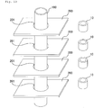
- one tube body 100 and four wall portions 200 are joined by press-fitting using four rubber members (elastic members) 10.
- the present embodiment is a conceptual example for facilitating understanding of the present invention. Therefore, a specific detailed configuration will be described in the second and subsequent embodiments.
- the tube body 100 is a circular tube and may be, for example, an aluminum pipe.
- the wall portion 200 is a plate-like body formed with a circular hole portion 201 through which the tube body 100 can be inserted, and may be a part of a component made of high-tension steel, for example.
- the one tube body 100 is inserted through the hole portions 201 of the four wall portions 200 of the same shape.
- the tube body 100 is expanded at four locations by the rubber member 10, and is joined to the wall portion 200 at the four locations by press-fitting.
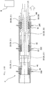
- a member joining device 1 of the present embodiment includes a tubular unit 20, a shaft unit 30, four rubber members 10, and a motion mechanism M that is conceptually illustrated.
- the member joining device 1 is shown with the rubber members 10 being separated for clarity of illustration, but is actually used with the rubber members 10 being combined as described later (see long dashed short dashed line with arrow in Fig. 2 ) .
- the tubular unit 20 of the present embodiment includes a tubular assembly 21 constituted by a single tubular member 22 and four flange portions (receiving portions) 22a.
- the tubular member 22 is a generally cylindrical member that extends in a first central axis L1 direction.
- An outer peripheral surface of the tubular member 22 is formed with the four flange portions (receiving portions) 22a.
- the positions of the four flange portions 22a in the direction of the first central axis L1 are fixed with respect to the tubular assembly 21.
- One of the four flange portions 22a is formed on the end surface of the tubular member 22.
- each of the four flange portions 22a is circular as viewed in the direction of the first central axis L1, and is large enough to allow the tubular member 22 to be inserted into the tube body 100.
- the flange portion 22a has a receiving surface 22c that is a flat surface perpendicular to the first central axis L1.
- the tubular member 22 is provided with four slits 22b that extend in the direction of the first central axis L1.
- the shaft unit 30 of the present embodiment includes a shaft assembly 31 constituted by a single shaft member 32 and four protrusion portions (pressing portions) 32b.
- the shaft member 32 has a generally columnar shaft 32a that extends in the direction of a second central axis L2, and a protrusion portion (pressing portion) 32b that protrudes radially outside the second central axis L2 is formed on the shaft 32a.
- the position of the protrusion portion 32b in the second central axis L2 direction is fixed with respect to the shaft assembly 31.
- Fig. 2 when the shaft unit 30 and the tubular unit 20 are combined, the directions of the first central axis L1 and the second central axis L2 are aligned with each other.
- the first central axis L1 and the second central axis L2 may be collectively referred to as the central axis L.
- Each of the protrusion portions 32b protrudes from the shaft 32a in two directions, and more specifically, is formed into an I-shape as viewed from the second central axis L2.
- the shaft 32a of the shaft member 32 is smaller than the inner diameter of the tubular member 22 in the radial direction, and the protrusion portion 32b is larger than the outer diameter of the tubular member 22.
- the shaft member 32 can be inserted into the tubular member 22, and in the inserted state, the protrusion portion 32b penetrates the tubular member 22 through the slit 22b of the tubular member 22 and protrudes radially outside the tubular member 22. Therefore, the shaft member 32 can linearly move in the central axis L direction partially inside and outside the tubular member 22.
- the protrusion portion 32b has a pushing surface 32c that is a flat surface perpendicular to the second central axis L2.
- the pushing surface 32c faces the receiving surface 22c of the flange portion 22a in the central axis L direction. Accordingly, the distance between the pushing surface 32c and the receiving surface 22c changes due to the above-described linear motion.
- the four rubber members 10 have a cylindrical shape with both end surfaces being flat surfaces, and are all the same.
- the rubber member 10 is preferably made of, for example, any of urethane rubber, chloroprene rubber, CNR rubber (chloroprene rubber and nitrile rubber), and silicon rubber.
- the hardness of the rubber member 10 is preferably 30 or more in Shore A.
- the member joining device 1 is configured by the tubular unit 20 being inserted into the shaft unit 30 and the rubber members 10 are respectively arranged radially outside the tubular member 22 between the flange portion 22a and the protrusion portion 32b.
- the tube body 100 is first inserted into the hole portions 201 of the four wall portions 200.
- the member joining device 1 shown in Fig. 2 is inserted inside the tube body 100 in a combined state.
- each of the rubber members 10 is aligned with the hole portion 201 of the wall portion 200 in the central axis L direction to fix the tubular unit 20.
- the motion mechanism M moves the shaft unit 30 in the central axis L direction with respect to the tubular unit 20 (see the arrow in Fig. 2 ) .
- each of the rubber members 10 is expanded toward the radially outside the central axis L, and as shown in Fig. 3 , each portion of the tube body 100 is expanded by the rubber member 10, and the tube body 100 is joined to the hole portion 201 of the wall portion 200 by press-fitting.
- the present invention is a conceptual example as mentioned earlier, and in practice, it is preferable to perform swaging and joining by increasing the area of the pushing surface 32c or using a member such as an annular indenter 40 (see Fig. 5 and the like) of the second embodiment and subsequent embodiments.
- the tube body 100 and the wall portion 200 can be simultaneously and accurately joined at four locations by press-fitting.
- the tube body 100 and the wall portion 200 can be joined at four locations by press-fitting with the four rubber members 10 arranged between the flange portion 22a and the protrusion portion 32b.
- the protrusion portions 32b since the position of each of the protrusion portions 32b in the central axis L direction is fixed with respect to the shaft assembly 31, the protrusion portions 32b move in synchronization with one another. Therefore, the joining at these four locations by press-fitting can be performed simultaneously.
- each of the rubber members 10 can be deformed at the accurate position, and each portion of the tube body 100 can be expanded at the accurate position. Accordingly, only a necessary portion of the tube body 100 can be accurately expanded without expanding an unnecessary portion of the tube body, and hence the tube body can be accurately joined by press-fitting.
- the protrusion portion 32b can protrude radially outside the central axis L from the tubular member 22. Since the slit 22b extends in the central axis L direction and the protrusion portion 32b is arranged to be linearly movable in the slit 22b, the shaft member 32 can be configured to be linearly movable in the central axis L direction inside the tubular member 22. That is, it is possible to easily realize the configuration that includes the flange portion 22a, which is immovable in the central axis L direction, and the protrusion portion 32b, which is movable in the central axis L direction.
- the member joining device 1 of the present embodiment is substantially the same as that of the first embodiment except for a detailed configuration. Accordingly, the same components as those in the configuration shown in the first embodiment are denoted by the same reference numerals and the description thereof may be omitted.
- the one tube body 100 and the two wall portions 200 are joined by press-fitting with the two rubber members 10.
- the tube body 100 is preferably arranged so as to horizontally extend from the viewpoint of ease of handling.
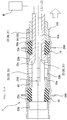
- the member joining device 1 of the present embodiment includes the tubular unit 20, the shaft unit 30, the rubber member 10, and the annular indenter (annular member) 40.
- the tubular unit 20 of the present embodiment includes the tubular assembly 21 constituted by a first tubular member 23 and a second tubular member 24, a flange portion 24a (receiving portion), and a base portion 51 (receiving portion), which is a part of a fixing base 50.
- the first tubular member 23 is a generally cylindrical member that extends in the first central axis L1 direction.
- One end portion of the first tubular member 23 is formed with four slits 23a.
- the four slits 23a are formed at equal intervals in the circumferential direction of the first tubular member 23 and extend in the first central axis L1 direction.
- the second tubular member 24 is also a generally cylindrical member that extends in the first central axis L1 direction.
- One end portion of the second tubular member 24 is formed with the flange portion 24a.
- the outer diameter of the flange portion 24a is circular as viewed from the first central axis L1 direction.
- the flange portion 24a has a receiving surface 24b that is a flat surface perpendicular to the first central axis L1 direction.
- One end surface of the second tubular member 24 is provided with a counterbore hole 24c (see Figs. 6A and 6B ), which is concave in the first central axis L1 direction.
- the counterbore hole 24c (see Figs. 6A and 6B ) is circular as viewed in the first central axis L1 direction, and is large enough to partially receive one end portion of the first tubular member 23.
- the shaft unit 30 of the present embodiment includes the shaft assembly 31 constituted by a single shaft member 33, a protrusion portion (pressing portion) 33b, and a plunger (pressing portion) 60.
- the shaft member 33 has a columnar shaft 33a that extends in the second central axis L2 direction, and the protrusion portion 33b that protrudes in four directions radially outside the second central axis L2.
- the position of the protrusion portion 33b in the second central axis L1 direction is fixed with respect to the shaft assembly 31.
- the protrusion portions 33b are formed at equal intervals in the circumferential direction of the shaft 33a, that is, they are formed in a cross shape as viewed from the second central axis L2 direction.
- the shaft 33a has a shape capable of being inserted into the second tubular member 24, and the protrusion portion 33b has a shape capable of being inserted into the slit 23a of the first tubular member 23. Therefore, the shaft member 33 can linearly move in the central axis L direction partially inside and outside the first tubular member 23.
- the protrusion portion 33b has a pushing surface 33c that is a flat surface perpendicular to the second central axis L2.
- the pushing surface 33c faces a receiving surface 52a of a standing hole portion 52 of the fixing base 50 in the central axis L direction. Accordingly, the distance between the pushing surface 33c and the receiving surface 52a changes due to the above-described linear motion.
- the two rubber members 10 of the present embodiment are substantially the same as those of the first embodiment, and are both cylindrical.
- the annular indenter 40 of the present embodiment is a cylindrical member with both end surfaces being flat surfaces.
- the annular indenter 40 has a shape capable of being arranged around the first tubular member 23, that is, the first tubular member 23 can be inserted into the annular indenter 40.
- the material of the annular indenter 40 is not particularly limited, but is preferably a material that does not deform due to the pressing force generated at the time of swaging and joining, and may be, for example, steel.
- the fixing base 50 includes the columnar base portion 51 and a bottomed cylindrical standing hole portion 52 that rises from the center of the base portion 51 in the second central axis L2 direction.
- the base portion 51 is fixed with bolts to a fixing surface such as a floor surface or a wall surface not shown.
- the standing hole portion 52 is large enough to partially receive the first tubular member 23 and has the receiving surface 52a that is a flat surface perpendicular to the second central axis L2.
- the plunger 60 has a bottomed cylindrical shape.
- the plunger 60 has a pushing surface 60a that is a flat surface perpendicular to the central axis L.
- the pushing surface 60a faces the receiving surface 24b of the flange portion 24a in the central axis L direction.
- the first tubular member 23 is inserted into the fixing base 50 with the fixing base 50 fixed, the rubber member 10 is arranged around the first tubular member 23, and subsequently the annular indenter 40 is arranged around the first tubular member 23.
- the protrusion portion 33b of the shaft member 33 is inserted into the slit 23a of the first tubular member 23, the second tubular member 24 is arranged around the shaft member 33, and the rubber member 10 is arranged around the second tubular member 24.
- the end portion of the shaft member 33 protrudes from the second tubular member 24 and the rubber member 10.
- the plunger 60 is arranged on the shaft member 33 so as to cover the protruding shaft member 33.
- the shaft member 33 is arranged radially inside the central axis L, the first tubular member 23 and the second tubular member 24 are arranged in the middle, and the annular indenter 40 and the rubber member 10 are arranged outside. That is, the member joining device 1 has a three-layer structure.
- the tubular unit 20 is immovable, and the shaft unit 30, the annular indenter 40, and the plunger 60 are movable.
- the tube body 100 is inserted into the hole portion 201 of the wall portion 200.
- the member joining device 1 is inserted inside the tube body 100.
- each of the rubber members 10 is aligned with the hole portion 201 of the wall portion 200 in the central axis L direction to fix the fixing base 50, that is, to fix the tubular unit 20.
- the tube body 100 and the wall portion 200 can be simultaneously and accurately joined at two locations by press-fitting.
- the tube body 100 and the wall portion 200 can be joined at two locations by press-fitting with the rubber member 10 arranged between the plunger 60 and the flange portion 24a of the second tubular member 24, and the rubber member 10 arranged between the annular indenter 40 and the base portion 51 of the fixing base 50.
- the plunger 60 and the protrusion portion 33b in the central axis L direction are fixed with respect to the shaft assembly 31, the plunger 60 and the protrusion portion 33b move in synchronization with each other. Therefore, the joining at these two locations by press-fitting can be performed simultaneously.
- the rubber member 10 is supported by the receiving surface 52a of the fixing base 50 and the rubber member 10 is supported by the receiving surface 24b of the flange portion 24a of the second tubular member 24, the positions of the two rubber members 10 in the central axis L direction do not change even at the time of swaging and joining. Therefore, each of the two rubber members 10 can be deformed at the accurate position, and each portion of the tube body 100 can be expanded at the accurate position. Accordingly, only a necessary portion of the tube body 100 can be accurately expanded without expanding an unnecessary portion of the tube body, and hence the tube body can be accurately joined by press-fitting.
- the protrusion portion 33b can protrude radially outside the central axis L from the first tubular member 23. Since the slit 23a extends in the central axis L direction and the protrusion portion 33b is arranged to be linearly movable in the slit 23a, the shaft member 33 can be configured to be linearly movable in the central axis L direction inside the tubular assembly 21. That is, it is possible to easily realize the configuration that includes the flange portion 24a and the fixing base 50, which are immovable in the central axis L direction, and the protrusion portion 33b and the plunger 60, which are movable in the central axis L direction.
- the rubber member 10 can be pressed uniformly by the plunger 60 and the rubber member 10 can be pressed uniformly by the annular indenter 40. If the annular indenter 40 is not provided, the protrusion portion 33b directly presses the rubber member 10, whereby since the shape of the protrusion portion 33b is a cross shaped, an unintended deformation of the rubber member 10 may be caused. Specifically, since the protrusion portion 33b has a shape that unevenly presses only a few locations of the surface of the rubber member 10, only the few unevenly pressed locations of the rubber member 10 may be unevenly deformed, and the tube body 100 may not be uniformly expanded.
- the protrusion portion 33b is formed point-symmetrically about the central axis L in a cross section perpendicular to the central axis L of the shaft member 33, and more specifically, is formed in a cross shape.
- Such a point-symmetric formation makes it easy to apply a force uniformly to the rubber member 10. That is, the possibility of causing an unintended deformation of the rubber member 10 as described above can be reduced.
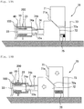
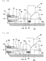
- Figs. 7A and 7B show a pressing mechanism 70, which is an example of the motion mechanism M (see Figs. 6A and 6B ).
- the pressing mechanism 70 includes a cam driver 71, a cam slider 72, a standing wall portion 73, and a cylindrical extrusion base 74.
- the cam driver 71 is arranged adjacent to the vertically upright standing wall portion 73 fixed to the floor surface, and is movable vertically along the standing wall portion 73.
- the cam driver 71 has an inclined surface 71a at its lower portion for transmitting a force to the cam slider 72.
- a press machine or the like that is usually used for pressing or the like may be used.
- the cam slider 72 has a rail mechanism (not shown) on its lower surface and is movable horizontally. However, other than the rail mechanism, it is possible to adopt any mechanism such as a wheel that reduces the frictional force with the ground when moving.
- the cam slider 72 has an inclined surface 72a on its upper portion for receiving a force from the cam driver 71. Therefore, the inclined surface 71a of the cam driver 71 and the inclined surface 72a of the cam slider 72 are formed so as to be inclined with respect to each other.
- the extrusion base 74 extends horizontally and has a flat pressing surface 74a for pressing the plunger 60. The extrusion base 74 is attached to the cam slider 72 and moves horizontally together with the cam slider 72.
- the cam driver 71 When a vertical force (downward in the figure) is applied to the cam driver 71, the force is transmitted from the cam driver 71 to the cam slider 72 via the inclined surfaces 71a and 72a. As a result, the cam driver 71 moves vertically _(downward in the figure) and the cam slider 72 moves horizontally (leftward in the figure). When the cam slider 72 moves, the extrusion base 74 also moves together and presses the plunger 60.
- the cam driver 71 and the cam slider 72 are an example of a cam mechanism.
- the standing wall portion 73 and the cam slider 72 are elastically connected to each other via a coil spring 75. Accordingly, the cam slider 72 is biased toward the standing wall portion 73.
- the cam mechanism can convert the acting direction of the force, the arrangement of the tube body 100 to be joined by press-fitting can be arbitrarily selected.
- a processing machine such as a press machine that applies a compression force applies a compression force in the vertical direction.
- the cam mechanism can convert a vertical force applied by a processing machine such as the normal press machine into a horizontal force, for instance. Accordingly, it is also possible to horizontally arrange the tube body 100 to be swaged and joined while using a processing machine such as the normal press machine.
- the tube body 100 when the tube body 100 is a long member, it is possibly joined with the plurality of wall portions 200 by press-fitting, and hence it is particularly effective that the swaging and joining can be simultaneously and accurately performed at a plurality of locations.
- a limit stroke is defined in a facility such as the normal pressing machine that vertically applies a compression force, there is a possibility that the swaging and joining cannot be performed due to the limitation of dimensions.
- the cam mechanism can convert the acting direction of the force, the swaging and joining can be performed by selecting an arbitrary arrangement that is not affected by the limit stroke without being subjected to dimension restriction.
- a third tubular member 25 in which the first tubular member 23 and the fixing base 50 shown in Figs. 6A and 6B are integrated may be used.
- the third tubular member 25 includes a flange portion 25a that has a receiving surface 25c corresponding to the receiving surface 52a of the fixing base 50, and a slit 25b corresponding to the slit 23a of the first tubular member 23.
- joining by press-fitting can be performed without providing the fixing base 50 (see Figs. 6A and 6B ). Accordingly, the number of components can be reduced, and the cost can be reduced.
- the position of the third tubular member 25 is fixed instead of the fixing base 50 (see Figs. 6A and 6B ).
- the second modification of the present embodiment three or more joint locations may be provided.
- the number of joint locations can be increased by continuously assembling the shaft member 33, the third tubular member 25, the annular indenter 40, and the rubber member 10 in addition to the configuration of the first modification described above.
- the third tubular member 25 includes a counterbore hole (not shown) for connection similar to the counterbore hole 24c of the second tubular member 24.
- three or more locations can be joined at one time. That is, by increasing the continuous configuration of the assembly, it is possible to arbitrarily increase the number of locations that can be joined at one time.
- the member joining device 1 of the present embodiment is substantially the same as that of the second modification of the second embodiment except for a detailed configuration. Accordingly, the same components as those in the configuration shown in the second modification of the second embodiment are denoted by the same reference numerals and the description thereof may be omitted.
- the member joining device 1 of the present embodiment includes the tubular unit 20, the shaft unit 30, the rubber member 10, the annular indenter 40, and a fixing plate 55 that has a flat surface.
- the end surface of the flange portion 25a of another third tubular member 25 is brought into contact with the above-mentioned third tubular member 25, the rubber member 10 is arranged around the third tubular member 25, and then the annular indenter 40 is arranged around the third tubular member 25.
- the shaft 33a of the shaft member 33 is inserted into the third tubular member 25, and the protrusion portion 33b is inserted into the slit 25b of the third tubular member 25.
- the two shaft members 33 are coupled by an arbitrary method such as screw fastening, and move integrally in the central axis L direction.
- the shaft member 33 is arranged radially inside the central axis L, the third tubular member 25 is arranged in the middle, and the annular indenter 40 and the rubber member 10 are arranged outside. That is, the member joining device 1 has a three-layer structure. In the central axis L direction, particularly the direction toward the fixing base 50, the tubular unit 20 is immovable, and the shaft unit 30 and the annular indenter 40 are movable.
- the tube body 100 is inserted into the hole portion 201 of the wall portion 200.
- the member joining device 1 is inserted inside the tube body 100.
- each of the rubber members 10 is aligned with the hole portion 201 of the wall portion 200 in the central axis L direction to fix the tubular unit 20.
- Figs. 11A and 11B show the pulling mechanism 80, which is an example of the motion mechanism M (see Fig. 9B ).
- the pulling mechanism 80 includes a cam driver 81, a cam slider 82, a standing wall portion 83, and a guide shaft member 84.
- the cam driver 81 is arranged adjacent to the vertically upright standing wall portion 83 fixed to the floor surface, and is movable vertically along the standing wall portion 83.
- the cam driver 81 has an inclined surface 81a at its lower portion for transmitting a force to the cam slider 82.
- a press machine or the like that is usually used for pressing or the like may be used.
- the cam slider 82 has a rail mechanism (not shown) on its lower surface and is movable horizontally.
- the cam slider 82 has an inclined surface 82a on its upper portion for receiving a force from the cam driver 81. Therefore, the inclined surface 81a of the cam driver 81 and the inclined surface 82a of the cam slider 82 are formed so as to be inclined with respect to each other.
- the guide shaft member 84 extends horizontally through the cam slider 82 and the standing wall portion 83.
- the cam slider 82 and the standing wall portion 83 have through-holes 82b and 83a, respectively, for receiving the guide shaft member 84, and the guide shaft member 84 can slide horizontally in the through-holes 82b and 83a.
- One end of the guide shaft member 84 is mechanically connected to the shaft member 33 by a coupling mechanism 84a, and the other end is connected to a locking member 84b such as a bolt that is larger than the through-hole 82b outside the cam slider 82 (opposite side of the standing wall portion 83).
- the standing wall portion 83 and the cam slider 82 are elastically connected to each other via a coil spring 85. Accordingly, the cam slider 82 is biased toward the standing wall portion 83.
- the cam driver 81 When a vertical force (downward in the figure) is applied to the cam driver 81, the force is transmitted from the cam driver 81 to the cam slider 82 via the inclined surfaces 81a and 82a. As a result, the cam driver 81 moves vertically (downward in the figure) and the cam slider 82 moves horizontally (rightward in the figure). When the cam slider 82 moves, the guide shaft member 84 having received the force via the locking member 84b also moves together, and pulls the shaft member 33 via the coupling mechanism 84a.
- the cam driver 81 and the cam slider 82 are an example of a cam mechanism.
- the standing wall portion 83 and the cam slider 82 are elastically connected to each other via a coil spring 85. Accordingly, the cam slider 82 is biased toward the standing wall portion 83.
- Figs. 12A and 12B in the modification of the present embodiment, three or more joint locations may be provided.
- the number of joint locations can be increased by continuously assembling the shaft member 33, the third tubular member 25, the annular indenter 40, and the rubber member 10 in addition to the configuration of the present embodiment ( Figs. 10A and 10B ).
- three or more locations can be joined at one time. That is, by increasing the continuous configuration of the assembly, it is possible to arbitrarily increase the number of locations that can be joined at one time.
- the materials of a tube body 100 and a wall portion 200 are not particularly limited, and may be different materials or the same material.
- the one tube body 100 and the four wall portions 200 are joined by press-fitting with the four rubber members (elastic members) 10.
- the present embodiment is a conceptual example for facilitating understanding of the present invention. Therefore, a specific detailed configuration will be described in the fifth and subsequent embodiments.
- the tube body 100 is a circular tube and may be, for example, an aluminum pipe.
- the wall portion 200 is a plate-like body formed with a circular hole portion 201 through which the tube body 100 can be inserted, and may be a part of a component made of high-tension steel, for example.
- the one tube body 100 is inserted through the hole portions 201 of the four wall portions 200 of the same shape.
- the tube body 100 is expanded at four locations by the rubber member 10, and is joined to the wall portion 200 at the four locations by press-fitting.
- a member joining device 1 of the present embodiment includes a tubular unit 20, a shaft unit 30, four rubber members 10, and a motion mechanism M that is conceptually illustrated.
- the member joining device 1 is shown with the rubber members 10 being separated for clarity of illustration, but is actually used with the rubber members 10 being combined as described later (see long dashed short dashed line with arrow in Fig. 14 ) .
- the tubular unit 20 of the present embodiment includes the tubular assembly 21 constituted by the single tubular member 22 and four flange portions (pressing portions) 22d.
- the tubular member 22 is a generally cylindrical member that extends in a first central axis L1 direction.
- An outer peripheral surface of the tubular member 22 is formed with the four flange portions (pressing portions) 22d.
- the positions of the four flange portions 22d in the direction of the first central axis L1 are fixed with respect to the tubular assembly 21.
- One of the four flange portions 22d is formed on the end surface of the tubular member 22.
- each of the four flange portions 22d is circular as viewed in the direction of the first central axis L1, and is large enough to allow the tubular member 22 to be inserted into the tube body 100.
- the flange portion 22d has a pushing surface 22e that is a flat surface perpendicular to the first central axis L1.
- the tubular member 22 is provided with four slits 22f that extend in the direction of the first central axis L1.
- the shaft unit 30 of the present embodiment includes a shaft assembly 31 constituted by a single shaft member 32 and four protrusion portions (receiving portions) 32b.
- the shaft member 32 has the generally columnar shaft 32a that extends in the direction of the second central axis L2, and the protrusion portion (receiving portion) 32b that protrudes radially outside the second central axis L2 is formed on the shaft 32a.
- the position of the protrusion portion 32b in the second central axis L2 direction is fixed with respect to the shaft assembly 31.
- the directions of the first central axis L1 and the second central axis L2 are aligned with each other.
- the first central axis L1 and the second central axis L2 may be collectively referred to as the central axis L.
- Each of the protrusion portions 32b protrudes from the shaft 32a in two directions, and more specifically, is formed into an I-shape as viewed from the second central axis L2.
- the shaft 32a of the shaft member 32 is smaller than the inner diameter of the tubular member 22 in the radial direction, and the protrusion portion 32b is larger than the outer diameter of the tubular member 22.
- the shaft member 32 can be inserted into the tubular member 22, and in the inserted state, the protrusion portion 32b penetrates the tubular member 22 through the slit 22f of the tubular member 22 and protrudes radially outside the tubular member 22. Therefore, the shaft member 32 can linearly move relative to the tubular member 22 in the central axis L direction partially inside and outside the tubular member 22.
- the protrusion portion 32b has the receiving surface 32c that is a flat surface perpendicular to the second central axis L2.
- the receiving surface 32c faces the pushing surface 22e of the flange portion 22d in the central axis L direction. Accordingly, the distance between the pushing surface 32c and the receiving surface 22e changes due to the above-described linear motion.
- the four rubber members 10 have a cylindrical shape with both end surfaces being flat surfaces, and are all the same.
- the rubber member 10 is preferably made of, for example, any of urethane rubber, chloroprene rubber, CNR rubber (chloroprene rubber and nitrile rubber), and silicon rubber.
- the hardness of the rubber member 10 is preferably 30 or more in Shore A.
- the member joining device 1 is configured by the tubular unit 20 being inserted into the shaft unit 30 and each of the rubber members 10 is arranged radially outside the tubular member 22 between the flange portion 22d and the protrusion portion 32b.
- the tube body 100 When swaging and joining, as shown in Fig. 13 , the tube body 100 is first inserted into the hole portions 201 of the four wall portions 200. Next, the member joining device 1 shown in Fig. 14 is inserted inside the tube body 100 in a combined state. At this time, each of the rubber members 10 is aligned with the hole portion 201 of the wall portion 200 in the central axis L direction to fix the shaft unit 30. After that, the motion mechanism M moves the tubular unit 20 in the central axis L direction with respect to the shaft unit 30 (see the arrow in Fig. 14 ).
- each of the rubber members 10 is expanded toward the radially outside the central axis L, and as shown in Fig. 15 , each portion of the tube body 100 is expanded by the rubber member 10, and the tube body 100 is joined to the hole portion 201 of the wall portion 200 by press-fitting.
- the present invention is a conceptual example as mentioned earlier, and in practice, it is preferable to perform swaging and joining by increasing the area of the receiving surface 32c or using a member such as the annular indenter 40 (see Fig. 17 and the like) of the second embodiment and subsequent embodiments.
- the tube body 100 and the wall portion 200 can be simultaneously and accurately joined at four locations by press-fitting.
- the tube body 100 and the wall portion 200 can be joined at four locations by press-fitting with the four rubber members 10 arranged between the flange portion 22d and the protrusion portion 32b.
- the position of the rubber member 10 in the central axis L direction does not change at the time of swaging and joining. Therefore, each of the rubber members 10 can be deformed at the accurate position, and each portion of the tube body 100 can be expanded at the accurate position. Accordingly, only a necessary portion of the tube body 100 can be accurately expanded without expanding an unnecessary portion of the tube body, and hence the tube body can be accurately joined by press-fitting.
- the protrusion portion 32b can protrude radially outside the central axis L from the tubular member 22.
- the slit 22f extends in the central axis L direction and the protrusion portion 32b is arranged to be relatively linearly movable in the slit 22f. Therefore, the tubular member 22 can be configured to be linearly movable in the central axis L direction outside the shaft member 32. That is, it is possible to easily realize the configuration that includes the protrusion portion 32b, which is immovable in the central axis L direction, and the flange portion 22d, which is movable in the central axis direction.
- the member joining device 1 of the present embodiment is substantially the same as that of the fourth embodiment except for a detailed configuration. Accordingly, the same components as those in the configuration shown in the fourth embodiment are denoted by the same reference numerals and the description thereof may be omitted.
- the one tube body 100 and the two wall portions 200 are joined by press-fitting with the two rubber members 10.
- the tube body 100 is preferably arranged so as to horizontally extend from the viewpoint of ease of handling.
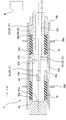
- the member joining device 1 of the present embodiment includes the tubular unit 20, the shaft unit 30, the rubber member 10, and the annular indenter (annular member) 40.
- the tubular unit 20 of the present embodiment includes the tubular assembly 21 constituted by the two first tubular members 23, and a flange portion 23b (pressing portion).
- the first tubular member 23 is a generally cylindrical member that extends in the first central axis L1 direction.
- One end portion of the first tubular member 23 is formed with the flange portion 23b.
- the outer diameter of the flange portion 23b is circular as viewed from the first central axis L1 direction.
- the flange portion 23b has a pushing surface 23c that is a flat surface perpendicular to the first central axis L1 direction.
- the other end of the first tubular member 23 is formed with four slits 23d.
- the four slits 23d are formed at equal intervals in the circumferential direction of the first tubular member 23 and extend in the first central axis L1 direction.
- One end surface of the first tubular member 23 is provided with a counterbore hole 23e, which is concave in the first central axis L1 direction.
- the counterbore hole 23e is circular as viewed in the first central axis L1 direction, and is large enough to partially receive the other end portion of another first tubular member 23.
- the shaft unit 30 of the present embodiment includes the shaft assembly 31 constituted by the two shaft members 33, and the protrusion portion (receiving portion) 33b.
- the shaft member 33 has a columnar shaft 33a that extends in the second central axis L2 direction, and the protrusion portion 33b that protrudes in four directions radially outside the second central axis L2.
- the position of the protrusion portion 33b in the second central axis L1 direction is fixed with respect to the shaft assembly 31.
- the protrusion portions 33b are formed at equal intervals in the circumferential direction of the shaft 33a, that is, they are formed in a cross shape as viewed from the second central axis L2 direction.
- the shaft 33a has a shape capable of being inserted into the first tubular member 23, and the protrusion portion 33b has a shape capable of being inserted into the slit 23d of the first tubular member 23. Therefore, when the tubular assembly 21 linearly moves in the central axis L direction, the shaft member 33 can linearly move relatively in the central axis L direction partially inside and outside the first tubular member 23.
- the protrusion portion 33b has the receiving surface 33c that is a flat surface perpendicular to the second central axis L2.
- the receiving surface 33c faces the pushing surface 23c in the central axis L direction. Accordingly, the distance between the pushing surface 33c and the receiving surface 23c changes due to the above-described linear motion.
- the two rubber members 10 of the present embodiment are substantially the same as those of the fourth embodiment, and are both cylindrical.
- the two annular indenters 40 of the present embodiment have the same shape and are cylindrical members with both end surfaces being flat surfaces.
- the annular indenter 40 has a shape capable of being arranged around each of the first tubular members 23, that is, the first tubular member 23 can be inserted into the annular indenter 40.
- the material of the annular indenter 40 is not particularly limited, but is preferably a material that does not deform due to the pressing force generated at the time of swaging and joining, and may be, for example, steel.
- the rubber member 10 when assembling these components, the rubber member 10 is arranged around the first tubular member 23, and subsequently, the annular indenter 40 is arranged around the first tubular member 23. Then, the shaft 33a of the shaft member 33 is inserted into the first tubular member 23, and the protrusion portion 33b is inserted into the slit 23d of the first tubular member 23. Next, another first tubular member 23 is coupled to the above-mentioned first tubular member 23. Then, the rubber member 10 is arranged around the first tubular member 23, and subsequently, the annular indenter 40 is arranged around the first tubular member 23.
- the shaft 33a of the shaft member 33 is inserted into the first tubular member 23, and the protrusion portion 33b is inserted into the slit 23d of the first tubular member 23.
- the shaft unit 30 is fixed so as to limit the motion in the central axis L direction.
- the shaft member 33 is arranged radially inside the central axis L
- the first tubular member 23 is arranged in the middle
- the annular indenter 40 and the rubber member 10 are arranged outside. That is, the member joining device 1 has a three-layer structure. In the central axis L direction, the shaft unit 30 and the annular indenter 40 are immovable, and the tubular unit 20 is movable.
- the tube body 100 is inserted into the hole portion 201 of the wall portion 200.
- the member joining device 1 is inserted inside the tube body 100.
- each of the rubber members 10 is aligned with the hole portion 201 of the wall portion 200 in the central axis L direction to fix the shaft unit 30.
- the conceptually shown motion mechanism M moves the tubular unit 20 in the central axis L direction (see the arrow in the figure) after the alignment.
- the space between the pushing surface 23c of the flange portion 23b and the receiving surface 33c of the protrusion portion 33b of the shaft member 33 (or the end surface of the annular indenter 40) is narrowed, and the rubber members 10 are each compressed in the central axis L direction.
- the rubber members 10 are each expanded toward the radially outside the central axis L, whereby the tube body 100 is expanded, and the tube body 100 is joined to the hole portion 201 of the wall portion 200 by press-fitting.
- the tube body 100 and the wall portion 200 can be simultaneously and accurately joined at two locations by press-fitting.
- the tube body 100 and the wall portion 200 can be joined at two locations by press-fitting with the two rubber members 10 each arranged between the protrusion portion 33b and the flange portion 23b.
- the flange portions 23b in the central axis L direction are fixed with respect to the tubular assembly 21, the flange portions 23b move in synchronization with one another. Therefore, the joining at these two locations by press-fitting can be performed simultaneously.
- the rubber member 10 since the rubber member 10 is supported by the receiving surface 33c of the protrusion portion 33b of the shaft member 33, the positions of the two rubber members 10 in the central axis L direction do not change even at the time of swaging and joining. Therefore, each of the two rubber members 10 can be deformed at the accurate position, and each portion of the tube body 100 can be expanded at the accurate position. Accordingly, only a necessary portion of the tube body 100 can be accurately expanded without expanding an unnecessary portion of the tube body, and hence the tube body can be accurately joined by press-fitting.
- the protrusion portion 33b can protrude radially outside the central axis L from the first tubular member 23. Since the slit 23d extends in the central axis L direction and the protrusion portion 33b is arranged to be relatively linearly movable in the slit 23d, the tubular assembly 21 can be configured to be linearly movable in the central axis L direction outside the shaft member 33. That is, it is possible to easily realize the configuration that includes the protrusion portion 33b, which is immovable in the central axis L direction, and the flange portion 23b, which is movable in the central axis direction.
- the rubber members 10 can be supported uniformly by the annular indenter 40. If the annular indenter 40 is not provided, the protrusion portion 33b directly supports the rubber member 10. Since the protrusion portion 33b has a cross shape, an unintended deformation of the rubber member 10 may be caused. Specifically, since the protrusion portion 33b has a shape that unevenly supports only a few locations of the surface of the rubber member 10, only the few unevenly pressed locations of the rubber member 10 may be unevenly deformed, and the tube body 100 may not be uniformly expanded.
- the protrusion portion 33b is formed point-symmetrically about the central axis L in a cross section perpendicular to the central axis L of the shaft member 33, and more specifically, is formed in a cross shape.
- Such a point-symmetric formation makes it easy to apply a force uniformly to the rubber member 10. That is, the possibility of causing an unintended deformation of the rubber member 10 as described above can be reduced.
- Figs. 19A and 19B show the pressing mechanism 70, which is an example of the motion mechanism M (see Figs. 18A and 18B ).
- the pressing mechanism 70 includes a cam driver 71, a cam slider 72, a standing wall portion 73, and a cylindrical extrusion base 74.
- the cam driver 71 is arranged adjacent to the vertically upright standing wall portion 73 fixed to the floor surface, and is movable vertically along the standing wall portion 73.
- the cam driver 71 has an inclined surface 71a at its lower portion for transmitting a force to the cam slider 72.
- a press machine or the like that is usually used for pressing or the like may be used.
- the cam slider 72 has a rail mechanism (not shown) on its lower surface and is movable horizontally. However, other than the rail mechanism, it is possible to adopt any mechanism such as a wheel that reduces the frictional force with the ground when moving.
- the cam slider 72 has an inclined surface 72a on its upper portion for receiving a force from the cam driver 71. Therefore, the inclined surface 71a of the cam driver 71 and the inclined surface 72a of the cam slider 72 are formed so as to be inclined with respect to each other.
- the extrusion base 74 extends horizontally and has the flat pressing surface 74a for pressing the first tubular member 23.
- the extrusion base 74 has a through-hole 74b having a circular cross section that extends horizontally. The through-hole 74b is large enough to receive the shaft 33a of the shaft member 33.
- the extrusion base 74 is attached to the cam slider 72 and moves horizontally together with the cam slider 72.
- the cam driver 71 When a vertical force (downward in the figure) is applied to the cam driver 71, the force is transmitted from the cam driver 71 to the cam slider 72 via the inclined surfaces 71a and 72a. As a result, the cam driver 71 moves vertically (downward in the figure) and the cam slider 72 moves horizontally (leftward in the figure). When the cam slider 72 moves, the extrusion base 74 also moves together and presses the first tubular member 23. At this time, since the shaft member 33 is inserted into the through-hole 74b, the shaft member 33 does not receive a force from the extrusion base 74.
- the cam driver 71 and the cam slider 72 are an example of a cam mechanism.
- the standing wall portion 73 and the cam slider 72 are elastically connected to each other via a coil spring 75. Accordingly, the cam slider 72 is biased toward the standing wall portion 73.
- the cam mechanism can convert the acting direction of the force, the arrangement of the tube body 100 to be swaged and joined can be arbitrarily selected.
- a processing machine such as a press machine that applies a compression force applies a compression force in the vertical direction.
- the cam mechanism can convert a vertical force applied by a processing machine such as the normal press machine into a horizontal force, for instance. Accordingly, it is also possible to horizontally arrange the tube body 100 to be swaged and joined while using a processing machine such as the normal press machine.
- the tube body 100 when the tube body 100 is a long member, it is possibly joined with the plurality of wall portions 200 by press-fitting, and hence it is particularly effective that the joining can be simultaneously and accurately performed at a plurality of locations by press-fitting.
- a limit stroke is defined in a facility such as the normal pressing machine that vertically applies a compression force
- the swaging and joining cannot be performed due to the limitation of dimensions.
- the cam mechanism can convert the acting direction of the force, the swaging and joining can be performed by selecting an arbitrary arrangement that is not affected by the limit stroke without being subjected to dimension restriction.
- three or more joint locations may be provided.
- the number of joint locations can be increased by continuously assembling the shaft member 33, the first tubular member 23, the annular indenter 40, and the rubber member 10 in addition to the configuration of the present embodiment.
- three or more locations can be joined at one time. That is, by increasing the continuous configuration of the assembly, it is possible to arbitrarily increase the number of locations that can be joined at one time.
- the member joining device 1 of the present embodiment is substantially the same as that of the fifth embodiment except for a detailed configuration. Accordingly, the same components as those in the configuration shown in the second embodiment are denoted by the same reference numerals and the description thereof may be omitted.
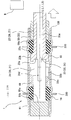
- the member joining device 1 of the present embodiment includes the tubular unit 20, the shaft unit 30, the rubber member 10, and the annular indenter 40.
- the shaft unit 30 of the present embodiment includes the shaft assembly 31 constituted by the single shaft member 33, the protrusion portion (receiving portion) 33b, and a support indenter (receiving portion) 56.
- the shaft member 33 is the same as that of the fifth embodiment.
- the support indenter 56 is a cylindrical member and has a receiving surface 56a that is a flat surface perpendicular to the second central axis L2.
- the support indenter 56 is configured to be capable of being fixed to a fixed object such as a floor surface, and when assembled as described later, the support indenter 56 is fixed and used.
- the rubber member 10 is arranged around the first tubular member 23, and subsequently, the annular indenter 40 is arranged around the first tubular member 23. Then, the protrusion portion 33b of the shaft member 33 is inserted into the slit 23d of the first tubular member 23. Next, another first tubular member 23 is coupled to the above-mentioned first tubular member 23. This coupling allows the two first tubular members 23 to move integrally in the central axis L direction by an arbitrary method such as screw fastening. Then, the rubber member 10 is arranged around the first tubular member 23, and subsequently, the support indenter 56 is arranged around the first tubular member 23.
- the shaft member 33 and the first tubular member 23 penetrate the support indenter 56. Then, the shaft unit 30 is fixed so as to limit the motion in the central axis L direction.
- the shaft member 33 is arranged radially inside the central axis L
- the first tubular member 23 is arranged in the middle
- the annular indenter 40 and the rubber member 10 are arranged outside. That is, the member joining device 1 has a three-layer structure. In the central axis L direction, the shaft unit 30, the annular indenter 40, and the support indenter 56 are immovable, and the tubular unit 20 is movable.
- the tube body 100 is inserted into the hole portion 201 of the wall portion 200.
- the member joining device 1 is inserted inside the tube body 100.
- each of the rubber members 10 is aligned with the hole portion 201 of the wall portion 200 in the central axis L direction to fix the shaft unit 30.
- the conceptually shown motion mechanism M pulls the tubular unit 20 in the central axis L direction (see the arrow in the figure) after the alignment. Then, the space between the end surface of the annular indenter 40 and the pushing surface 23c of the flange portion 23b is narrowed, and the rubber members 10 are each compressed in the central axis L direction. With this compression, the rubber members 10 are each expanded toward the radially outside the central axis L, whereby the tube body 100 is expanded, and the tube body 100 is joined to the hole portion 201 of the wall portion 200 by press-fitting.
- Figs. 22A and 22B show the pulling mechanism 80, which is an example of the motion mechanism M (see Figs. 21A and 21B ).
- the pulling mechanism 80 includes the cam driver 81, the cam slider 82, the standing wall portion 83, the guide shaft member 84, and a fixture 85.
- the cam driver 81 is arranged adjacent to the vertically upright standing wall portion 83 fixed to the floor surface, and is movable vertically along the standing wall portion 83.
- the cam driver 81 has an inclined surface 81a at its lower portion for transmitting a force to the cam slider 82.
- a press machine or the like that is usually used for pressing or the like may be used.
- the cam slider 82 has a rail mechanism (not shown) on its lower surface and is movable horizontally. However, other than the rail mechanism, it is possible to adopt any mechanism such as a wheel that reduces the frictional force with the ground when moving.
- the cam slider 82 has an inclined surface 82a on its upper portion for receiving a force from the cam driver 81. Therefore, the inclined surface 81a of the cam driver 81 and the inclined surface 82a of the cam slider 82 are formed so as to be inclined with respect to each other.
- the guide shaft member 84 extends horizontally through the cam slider 82 and the standing wall portion 83.
- the cam slider 82 and the standing wall portion 83 have through-holes 82b and 83a, respectively, for receiving the guide shaft member 84, and the guide shaft member 84 can slide horizontally in the through-holes 82b and 83a.
- One end of the guide shaft member 84 is mechanically connected to the first tubular member 23 by the coupling mechanism 84a, and the other end is connected to the locking member 84b such as a bolt that is larger than the through-hole 82b outside the cam slider 82 (opposite side of the standing wall portion 83).
- the fixture 85 fixes the support indenter 56 to the floor surface.
- the standing wall portion 83 and the cam slider 82 are elastically connected to each other via a coil spring 86. Accordingly, the cam slider 82 is biased toward the standing wall portion 83.
- the cam driver 81 When a vertical force (downward in the figure) is applied to the cam driver 81, the force is transmitted from the cam driver 81 to the cam slider 82 via the inclined surfaces 81a and 82a. As a result, the cam driver 81 moves vertically (downward in the figure) and the cam slider 82 moves horizontally (rightward in the figure). When the cam slider 82 moves, the guide shaft member 84 having received the force via the locking member 84b also moves together, and pulls the first tubular member 23 via the coupling mechanism 84a.
- the cam driver 81 and the cam slider 82 are an example of a cam mechanism.
- the standing wall portion 83 and the cam slider 82 are elastically connected to each other via a coil spring 86. Accordingly, the cam slider 82 is biased toward the standing wall portion 83.
- the flange portion 23b may be separated from the first tubular member 23 shown in Figs. 21A and 21B . That is, the first tubular member 23 may be separated into the second tubular member 24 and a pressing base 61.
- the second tubular member 24 is generally cylindrical, and its one end portion is formed with a same slit 24d as that of the first tubular member 23.
- the pressing base 61 is generally columnar, and includes a concave seat portion 61a where the first tubular member 23 can be inserted and placed.
- the pressing base 61 includes a pushing surface 61b that is perpendicular to the central axis L and faces the receiving surface 33c of the shaft member 33.
- the second tubular member 24 and the pressing base 61 are coupled by an arbitrary method such as screw fastening, and can move integrally in the central axis L direction.
- the degree of freedom in assembling the member joining device 1 can be improved.
- Figs. 24A and 24B in the modification of the present embodiment, three or more joint locations may be provided.
- the number of joint locations can be increased by continuously assembling the shaft member 33, the first tubular member 23, the annular indenter 40, and the rubber member 10 in addition to the configuration of the present embodiment ( Figs. 22A and 22B ).
- three or more locations can be joined at one time. That is, by increasing the continuous configuration of the assembly, it is possible to arbitrarily increase the number of locations that can be joined at one time.
Landscapes
- Engineering & Computer Science (AREA)
- Mechanical Engineering (AREA)
- Pressure Welding/Diffusion-Bonding (AREA)
- Standing Axle, Rod, Or Tube Structures Coupled By Welding, Adhesion, Or Deposition (AREA)
- Insertion Pins And Rivets (AREA)
- Mutual Connection Of Rods And Tubes (AREA)
Abstract
Description
- The present invention relates to a member joining device and a member joining method.
- A lower-density and high-strength metal called high-tension steel is used to reduce weight and improve safety of vehicles. Although the high-tension steel is effective in reducing weight and improving safety, it is heavier than a lower-density material such as an aluminum alloy. Because of its high strength, use of high-tension steel causes problems such as a decrease in formability, an increase in forming load, and a decrease in dimensional accuracy. In order to solve these problems, in recent years, extrusion materials, cast products, and press molded products of aluminum alloys having lower specific gravity than steel have been used for vehicle components. Since this aluminum alloy has a low specific gravity, it is effective for weight reduction but has a low strength. For this reason, there has been multi-materialization being carried out, in which steel components such as high-tension steel and aluminum alloy components are used in combination.
- A problem in this multi-materialization is the joining of dissimilar metals such as steel components and aluminum alloy components. For example,
Patent Document 1 discloses a member joining method that enables joining of dissimilar metals in the multi-materialization by using an elastic body. Specifically, in the member joining method ofPatent Document 1, an aluminum pipe is inserted into a hole portion of a steel component, a rubber member (elastic body) is inserted inside the aluminum pipe, and the rubber member is deformed by pressurizing, thereby expanding and deforming the aluminum pipe, and the steel component and the aluminum pipe are joined together by press-fitting. - Patent Document 1:
JP 2016-147309 A - In the joining method of
Patent Document 1, simultaneous, accurate swaging and joining of a plurality of locations has not been studied in detail. When a plurality of locations are simultaneously swaged and joined with the joining method ofPatent Document 1, the positions of the rubber members arranged at the plurality of locations are shifted, which may make it impossible to perform the joining at accurate positions by press-fitting. - An object of the present invention is to provide a member joining device and a member joining method that are capable of simultaneously and accurately joining a tube body and a wall portion at a plurality of locations by press-fitting.
- A member joining device of a first aspect of the present invention includes:
- a tubular unit that includes a tubular assembly that is fixed and has a first central axis, and a first receiving portion and a second receiving portion whose positions in a first central axis direction are fixed with respect to the tubular assembly;
- a shaft unit that includes a shaft assembly that is inserted into the tubular assembly in a linearly movable manner and has a second central axis that extends in the same direction as the first central axis, and a first pressing portion and a second pressing portion whose positions in a second central axis direction are fixed with respect to the shaft assembly, wherein the first pressing portion and the second pressing portion are positioned radially outside the first central axis of the tubular assembly, the first pressing portion faces the first receiving portion in the first and second central axis directions, and the second pressing portion faces the second receiving portion in the first and second central axis directions;
- a first elastic member arranged radially outside the first central axis of the tubular assembly, between the first pressing portion and the first receiving portion in the first and second central axis directions;
- a second elastic member arranged radially outside the first central axis of the tubular assembly, between the second pressing portion and the second receiving portion in the first and second central axis directions; and
- a motion mechanism that moves the shaft unit in the first and second central axis directions with respect to the tubular unit.
- According to this configuration, it is possible to simultaneously and accurately join the tube body and the wall portion at a plurality of locations by press-fitting in accordance with the following usage. First, the tube body is inserted into hole portions of a plurality of wall portions. Next, the member joining device is inserted inside the tube body. At this time, the first elastic member and the second elastic member (hereinafter, they are simply referred to as elastic members in some cases) are aligned with the hole portions of the respective wall portions in the first and second central axis directions (hereinafter they are simply referred to as central axes in some cases). Then, the motion mechanism moves the shaft unit in the central axis direction with respect to the tubular unit. In the above configuration, the first receiving portion and the second receiving portion (hereinafter they are simply referred to as receiving portions in some cases) are immovable in the central axis direction, and the first pressing portion and the second pressing portion (hereinafter they are simply referred to as pressing portions in some cases) are movable in the central axis direction. That is, movement of the shaft unit allows the pressing portion to approach the receiving portion, whereby the elastic member can be compressed in the central axis direction. With this compression, the elastic members are each expanded toward the radially outside the central axis, whereby the tube body is expanded, and the tube body is joined to the hole portion of the wall portion by press-fitting. Here, the radial direction of the central axis means the radial direction of the column when a column having the central axis is assumed.
- In particular, in the above configuration, the tube body and the wall portion can be joined at a plurality of locations by press-fitting with the first elastic member, which is arranged between the first pressing portion and the first receiving portion, and the second elastic member, which is arranged between the second pressing portion and the second receiving portion. It is to be noted that the joining locations are not limited to two locations but may be three or more.
- According to this configuration, since the positions of the first pressing portion and the second pressing portion in the central axis direction are fixed with respect to the shaft assembly, the first pressing portion and the second pressing portion move in synchronization with each other. Therefore, the joining at the plurality of locations by press-fitting can be performed simultaneously.
- According to this configuration, since the elastic member is supported by the receiving portion, the position of the elastic member in the central axis direction does not change at the time of swaging and joining. Therefore, each of the plurality of elastic members can be deformed at an accurate position, and each portion of the tube body can be expanded at an accurate position. Accordingly, only a necessary portion of the tube body can be accurately expanded without expanding an unnecessary portion of the tube body, and hence the tube body can be accurately joined by press-fitting.
- The tubular assembly may be provided with a slit that extends in the first central axis direction, and at least one of the first pressing portion and the second pressing portion penetrates the tubular assembly through the slit and protrudes radially outside the first central axis of the tubular assembly, and may be arranged to be linearly movable in the slit.
- According to this configuration, since the slit in the tubular assembly is provided, at least one of the first pressing portion and the second pressing portion can protrude radially outside the central axis from the tubular assembly. Since the slit extends in the central axis direction and at least one of the first pressing portion and the second pressing portion is arranged to be linearly movable in the slit, the shaft assembly can be configured to be linearly movable in the central axis direction inside the tubular assembly. That is, it is possible to easily realize the configuration that includes the first receiving portion and the second receiving portion, which are immovable in the central axis direction, and the first pressing portion and the second pressing portion, which are movable in the central axis direction.
- The member joining device may further include at least one of a first annular member that is arranged radially outside the first central axis of the tubular assembly, between the first pressing portion and the first elastic member in the first and second central axis directions, and a second annular member that is arranged radially outside the first central axis of the tubular assembly, between the second pressing portion and the second elastic member in the first and second central axis directions.
- According to this configuration, the first elastic member can be pressed uniformly by the first annular member and/or the second elastic member can be pressed uniformly by the second annular member. If the first annular member and the second annular member (hereinafter, they are simply referred to as annular members in some cases) are not provided, the pressing portion directly presses the elastic member, whereby an unintended deformation of the elastic member may be caused depending on the shape of the pressing portion. For example, in the case where the pressing portion has a shape that unevenly presses only a few locations of the surface of the elastic member, only the few unevenly pressed locations of the elastic member are unevenly deformed, and the tube body cannot be uniformly expanded. However, as in the configuration described above, when the elastic member is pressed via the annular member, a force can be uniformly applied to the elastic member over the circumferential direction of the central axis, and it is hence possible to prevent an unintended deformation of the elastic member and to stably perform joining by press-fitting.
- At least one of the first pressing portion and the second pressing portion may be formed point-symmetrically about the first and second central axes in a cross section perpendicular to the first and second central axis directions.
- According to this configuration, since the pressing portion is formed point-symmetrically as described above, it is easy to apply a force uniformly to the elastic member. That is, the possibility of causing an unintended deformation of the elastic member as described above can be reduced. The shape of the pressing portion may be, for example, a cross or other radiating shape in the cross section.
- The motion mechanism may include a cam mechanism that converts a force acting in a direction other than the first and second central axis directions into a force in the first and second central axis directions.
- According to this configuration, since the cam mechanism can convert the acting direction of the force, the arrangement of the tube body to be swaged and joined can be arbitrarily selected. For example, normally, a processing machine such as a press machine that applies a compression force applies a compression force in the vertical direction. The cam mechanism can convert a vertical force applied by a processing machine such as the normal press machine into a horizontal force, for instance. Accordingly, it is also possible to horizontally arrange the tube body to be swaged and joined while using a processing machine such as the normal press machine. Furthermore, when the tube body is a long member, it is possibly joined with the plurality of wall portions by press-fitting, and hence it is particularly effective that the joining by press-fitting can be simultaneously and accurately performed at a plurality of locations. However, when the tube body is a long member, since a limit stroke is defined in a facility such as the normal pressing machine that vertically applies a compression force, there is a possibility that the swaging and joining cannot be performed due to the limitation of dimensions. However, in the above configuration, since the cam mechanism can convert the acting direction of the force, the swaging and joining can be performed by selecting an arbitrary arrangement that is not affected by the limit stroke without being subjected to dimension restriction.
- The motion mechanism may be a pressing mechanism that presses the shaft unit.
- According to this configuration, the pressing mechanism presses the shaft unit to move it in the central axis direction with respect to the tubular unit, and the tube body and the wall portion can be simultaneously and accurately joined at a plurality of locations by press-fitting.
- The motion mechanism may be a pulling mechanism that pulls the shaft unit.
- According to this configuration, the pulling mechanism pulls the shaft unit to move it in the central axis direction with respect to the tubular unit, and the tube body and the wall portion can be simultaneously and accurately joined at a plurality of locations by press-fitting. In particular, in the case where the shaft unit is pulled to be swaged and joined, an unintended movement of the tube body and the wall portion can be suppressed more often than that in the case where the shaft unit is pressed to be swaged and joined, and it is hence possible to stably perform joining by press-fitting.
- A member joining method according to the first aspect of the present invention includes:
- providing a tube body, at least two wall portions provided with hole portions, and the member joining device;
- inserting the tube body through the hole portions of at least the two wall portions;
- inserting the member joining device inside the tube body; and
- compressing the first elastic member and the second elastic member in the first central axis direction by the member joining device to expand the elastic members radially outward, and thereby expanding and deforming at least two locations of the tube body to join the tube body to the hole portions of at least the two wall portions by press-fitting.
- According to this method, as described above, since the position of the elastic member is not shifted at the time of swaging and joining, it is possible to simultaneously and accurately join the tube body and the wall portion at a plurality of locations by press-fitting.
- A member joining device of a second aspect of the present invention includes:
- a tubular unit that includes a tubular assembly that has a first central axis and can linearly move in the first central axis direction, and a first pressing portion and a second pressing portion whose positions in a first central axis direction are fixed with respect to the tubular assembly;
- a shaft unit that includes a shaft assembly that is inserted into the tubular assembly and has a second central axis that extends in the same direction as the first central axis, and a first receiving portion and a second receiving portion whose positions in a second central axis direction are fixed with respect to the tubular assembly, wherein the first receiving portion and the second receiving portion are positioned radially outside the first central axis of the tubular assembly, the first receiving portion faces the first pressing portion in the first and second central axis directions, and the second receiving portion faces the second pressing portion in the first and second central axis directions;
- a first elastic member arranged radially outside the first central axis of the tubular assembly, between the first pressing portion and the first receiving portion in the first and second central axis directions;
- a second elastic member arranged radially outside the first central axis of the tubular assembly, between the second pressing portion and the second receiving portion in the first and second central axis directions; and
- a motion mechanism that moves the tubular unit in the first and second central axis directions with respect to the shaft unit.
- According to this configuration, it is possible to simultaneously and accurately join the tube body and the wall portion at a plurality of locations by press-fitting in accordance with the following usage. First, the tube body is inserted into hole portions of a plurality of wall portions. Next, the member joining device is inserted inside the tube body. At this time, the first elastic member and the second elastic member (hereinafter, they are simply referred to as elastic members in some cases) are aligned with the hole portions of the respective wall portions in the first and second central axis directions (hereinafter they are simply referred to as central axes in some cases). Then, the motion mechanism moves the tubular unit in the central axis direction with respect to the shaft unit. In the above configuration, the first receiving portion and the second receiving portion (hereinafter they are simply referred to as receiving portions in some cases) are immovable in the central axis direction, and the first pressing portion and the second pressing portion (hereinafter they are simply referred to as pressing portions in some cases) are movable in the central axis direction. That is, movement of the tubular unit allows the pressing portion to approach the receiving portion, whereby the elastic member can be compressed in the central axis direction. With this compression, the elastic members are each expanded toward the radially outside the central axis, whereby the tube body is expanded, and the tube body is joined to the hole portion of the wall portion by press-fitting. Here, the radial direction of the central axis means the radial direction of the column when a column having the central axis is assumed.
- In particular, in the above configuration, the tube body and the wall portion can be joined at a plurality of locations by press-fitting with the first elastic member, which is arranged between the first pressing portion and the first receiving portion, and the second elastic member, which is arranged between the second pressing portion and the second receiving portion. It is to be noted that the joining locations are not limited to two locations but may be three or more.
- According to this configuration, since the positions of the first pressing portion and the second pressing portion in the central axis direction are fixed with respect to the tubular assembly, the first pressing portion and the second pressing portion move in synchronization with each other. Therefore, the joining at the plurality of locations by press-fitting can be performed simultaneously.
- According to this configuration, since the elastic member is supported by the receiving portion, the position of the elastic member in the central axis direction does not change at the time of swaging and joining. Therefore, each of the plurality of elastic members can be deformed at an accurate position, and each portion of the tube body can be expanded at an accurate position. Accordingly, only a necessary portion of the tube body can be accurately expanded without expanding an unnecessary portion of the tube body, and hence the tube body can be accurately joined by press-fitting.
- The tubular assembly is provided with a slit that extends in the first central axis direction, and at least one of the first receiving portion and the second receiving portion may penetrate the tubular assembly at the slit and protrude radially outside the first central axis of the tubular assembly.
- According to this configuration, by providing the slit in the tubular assembly, at least one of the first receiving portion and the second receiving portion can protrude radially outside the central axis from the tubular assembly. Since the slit extends in the central axis direction, the tubular assembly can be configured to be linearly movable in the central axis direction outside the shaft assembly. That is, it is possible to easily realize the configuration that includes the first receiving portion and the second receiving portion, which are immovable in the central axis direction, and the first pressing portion and the second pressing portion, which are movable in the central axis direction.
- The member joining device may further include at least one of a first annular member that is arranged radially outside the first central axis of the tubular assembly, between the first receiving portion and the first elastic member in the first and second central axis directions, and a second annular member that is arranged radially outside the first central axis of the tubular assembly, between the second receiving portion and the second elastic member in the first and second central axis directions.
- According to this configuration, the first elastic member can be supported uniformly by the first annular member and the second elastic member can be supported uniformly by the second annular member. If the first annular member and the second annular member (hereinafter, they are simply referred to as annular members in some cases) are not provided, the receiving portion directly supports the elastic member, whereby an unintended deformation of the elastic member may be caused depending on the shape of the receiving portion. For example, in the case where the receiving portion has a shape that unevenly supports only a few locations of the surface of the elastic member, only the few unevenly supported locations of the elastic member are unevenly deformed, and the tube body cannot be uniformly expanded. However, as in the configuration described above, when the elastic member is supported through the annular member, a force can be uniformly applied to the elastic member over the circumferential direction of the central axis, and it is hence possible to prevent an unintended deformation of the elastic member and to stably perform joining by press-fitting.
- At least one of the first receiving portion and the second receiving portion may be formed point-symmetrically about the first and second central axes in a cross section perpendicular to the first and second central axis directions.
- According to this configuration, since the receiving portion is formed point-symmetrically as described above, it is easy to apply a force uniformly to the elastic member. That is, the possibility of causing an unintended deformation of the elastic member as described above can be reduced. The shape of the receiving portion may be, for example, a cross or other radiating shape in the cross section.
- The motion mechanism may include a cam mechanism that converts a force acting in a direction other than the first and second central axis directions into a force in the first and second central axis directions.
- According to this configuration, since the cam mechanism can convert the acting direction of the force, the arrangement of the tube body to be swaged and joined can be arbitrarily selected. For example, normally, a processing machine such as a press machine that applies a compression force applies a compression force in the vertical direction. The cam mechanism can convert a vertical force applied by a processing machine such as the normal press machine into a horizontal force, for instance. Accordingly, it is also possible to horizontally arrange the tube body to be swaged and joined while using a processing machine such as the normal press machine. Furthermore, when the tube body is a long member, it is possibly joined with the plurality of wall portions by press-fitting, and hence it is particularly effective that the joining can be simultaneously and accurately performed at a plurality of locations by press-fitting. However, when the tube body is a long member, since a limit stroke is defined in a facility such as the normal pressing machine that vertically applies a compression force, there is a possibility that the joining by press-fitting cannot be performed due to the limitation of dimensions. However, in the above configuration, since the cam mechanism can convert the acting direction of the force, the joining by press-fitting can be performed by selecting an arbitrary arrangement that is not affected by the limit stroke without being subjected to dimension restriction.
- The motion mechanism may be a pressing mechanism that presses the tubular unit.
- According to this configuration, the pressing mechanism presses the shaft unit to move it in the central axis direction with respect to the tubular unit, and the tube body and the wall portion can be simultaneously and accurately joined at a plurality of locations by press-fitting.
- The motion mechanism may be a pulling mechanism that pulls the tubular unit.
- According to this configuration, the pulling mechanism pulls the shaft unit to move it in the central axis direction with respect to the tubular unit, and the tube body and the wall portion can be simultaneously and accurately joined at a plurality of locations by press-fitting. In particular, in the case where the shaft unit is pulled to be swaged and joined, an unintended movement of the tube body and the wall portion can be suppressed more often than that in the case where the shaft unit is pressed to be swaged and joined, and it is hence possible to stably perform joining by press-fitting.
- A member joining method according to the second aspect of the present invention includes:
- providing a tube body, at least two wall portions provided with hole portions, and the member joining device;
- inserting the tube body through the hole portions of at least the two wall portions;
- inserting the member joining device into an inside of the tube body; and
- compressing the first elastic member and the second elastic member in the first central axis direction by the member joining device to expand the elastic members radially outside, and thereby expanding and deforming at least two locations of the tube body, to join the hole portions of at least the two wall portions by press-fitting.
- According to this method, as described above, since the position of the elastic member is not shifted at the time of swaging and joining, it is possible to simultaneously and accurately join the tube body and the wall portion at a plurality of locations by press-fitting.
- According to the present invention, in the member joining device and the member joining method, it is possible to simultaneously and accurately join the tube body and the wall portion at a plurality of locations by press-fitting.
-
-
Fig. 1 is a perspective view showing a tube body, a wall portion, and a rubber member; -
Fig. 2 is a perspective view of a member joining device according to a first embodiment of the present invention; -
Fig. 3 is a sectional view of the tube body and the wall portion after joining; -
Fig. 4 is a perspective view showing the tube body, the wall portion, and the rubber member; -
Fig. 5 is an exploded perspective view of a member joining device according to a second embodiment; -
Fig. 6A is a partial sectional view of the member joining device according to the second embodiment before swaging and joining; -
Fig. 6B is a partial sectional view of the member joining device according to the second embodiment after swaging and joining; -
Fig. 7A is a side view of a motion mechanism before pressing; -
Fig. 7B is a side view of the motion mechanism after pressing; -
Fig. 8A is a partial sectional view of a first modification of the member joining device according to the second embodiment before swaging and joining; -
Fig. 8B is a partial sectional view of the first modification of the member joining device according to the second embodiment after swaging and joining; -
Fig. 9A is a partial sectional view of a second modification of the member joining device according to the second embodiment before swaging and joining; -
Fig. 9B is a partial sectional view of the second modification of the member joining device according to the second embodiment after swaging and joining; -
Fig. 10A is a partial sectional view of a member joining device according to a third embodiment before swaging and joining; -
Fig. 10B is a partial sectional view of the member joining device according to the third embodiment after swaging and joining; -
Fig. 11A is a side view of the motion mechanism before pulling; -
Fig. 11B is a side view of the motion mechanism after pulling; -
Fig. 12A is a partial sectional view of a modification of the member joining device according to the third embodiment before swaging and joining; -
Fig. 12B is a partial sectional view of the modification of the member joining device according to the third embodiment after swaging and joining; -
Fig. 13 is a perspective view showing the tube body, the wall portion, and the rubber member; -
Fig. 14 is a perspective view of the member joining device according to a fourth embodiment; -
Fig. 15 is a sectional view showing the tube body and the wall portion after joining; -
Fig. 16 is a perspective view showing the tube body, the wall portion, and the rubber member; -
Fig. 17 is an exploded perspective view of a member joining device according to a fifth embodiment; -
Fig. 18A is a partial sectional view of the member joining device according to the fifth embodiment before swaging and joining; -
Fig. 18B is a partial sectional view of the member joining device according to the fifth embodiment after swaging and joining; -
Fig. 19A is a partial sectional view of the motion mechanism before pressing; -
Fig. 19B is a partial sectional view of the motion mechanism after pressing; -
Fig. 20A is a partial sectional view of a modification of the member joining device according to the fifth embodiment before swaging and joining; -
Fig. 20B is a partial sectional view of a modification of the member joining device according to the fifth embodiment after swaging and joining; -
Fig. 21A is a partial sectional view of a member joining device according to a sixth embodiment before swaging and joining; -
Fig. 21B is a partial sectional view of the member joining device according to the sixth embodiment after swaging and joining; -
Fig. 22A is a partial sectional view of the motion mechanism before pulling; -
Fig. 22B is a partial sectional view of the motion mechanism after pulling; -
Fig. 23A is a partial sectional view of a first modification of the member joining device according to the sixth embodiment before swaging and joining; -
Fig. 23B is a partial sectional view of the first modification of the member joining device according to the sixth embodiment after swaging and joining; -
Fig. 24A is a partial sectional view of a second modification of the member joining device according to the sixth embodiment before swaging and joining; and -
Fig. 24B is a partial sectional view of the second modification of the member joining device according to the sixth embodiment after swaging and joining. - Embodiments (first to third embodiments) of the first aspect of the present invention will be described below with reference to the accompanying drawings. In the following embodiments, the materials of a
tube body 100 and awall portion 200 are not particularly limited, and may be different materials or the same material. - As shown in
Fig. 1 , in the present embodiment, onetube body 100 and fourwall portions 200 are joined by press-fitting using four rubber members (elastic members) 10. The present embodiment is a conceptual example for facilitating understanding of the present invention. Therefore, a specific detailed configuration will be described in the second and subsequent embodiments. - As shown in
Fig. 1 , thetube body 100 is a circular tube and may be, for example, an aluminum pipe. Thewall portion 200 is a plate-like body formed with acircular hole portion 201 through which thetube body 100 can be inserted, and may be a part of a component made of high-tension steel, for example. In the present embodiment, the onetube body 100 is inserted through thehole portions 201 of the fourwall portions 200 of the same shape. Thetube body 100 is expanded at four locations by therubber member 10, and is joined to thewall portion 200 at the four locations by press-fitting. - As shown in
Fig. 2 , amember joining device 1 of the present embodiment includes atubular unit 20, ashaft unit 30, fourrubber members 10, and a motion mechanism M that is conceptually illustrated. InFig. 2 , themember joining device 1 is shown with therubber members 10 being separated for clarity of illustration, but is actually used with therubber members 10 being combined as described later (see long dashed short dashed line with arrow inFig. 2 ) . - The
tubular unit 20 of the present embodiment includes atubular assembly 21 constituted by asingle tubular member 22 and four flange portions (receiving portions) 22a. Thetubular member 22 is a generally cylindrical member that extends in a first central axis L1 direction. An outer peripheral surface of thetubular member 22 is formed with the four flange portions (receiving portions) 22a. In other words, the positions of the fourflange portions 22a in the direction of the first central axis L1 are fixed with respect to thetubular assembly 21. One of the fourflange portions 22a is formed on the end surface of thetubular member 22. The outer shape of each of the fourflange portions 22a is circular as viewed in the direction of the first central axis L1, and is large enough to allow thetubular member 22 to be inserted into thetube body 100. Theflange portion 22a has a receivingsurface 22c that is a flat surface perpendicular to the first central axis L1. Thetubular member 22 is provided with fourslits 22b that extend in the direction of the first central axis L1. - The
shaft unit 30 of the present embodiment includes ashaft assembly 31 constituted by asingle shaft member 32 and four protrusion portions (pressing portions) 32b. Theshaft member 32 has a generallycolumnar shaft 32a that extends in the direction of a second central axis L2, and a protrusion portion (pressing portion) 32b that protrudes radially outside the second central axis L2 is formed on theshaft 32a. In other words, the position of theprotrusion portion 32b in the second central axis L2 direction is fixed with respect to theshaft assembly 31. As shown inFig. 2 , when theshaft unit 30 and thetubular unit 20 are combined, the directions of the first central axis L1 and the second central axis L2 are aligned with each other. Therefore, in the state where theshaft unit 30 and thetubular unit 20 are combined, the first central axis L1 and the second central axis L2 may be collectively referred to as the central axis L. Each of theprotrusion portions 32b protrudes from theshaft 32a in two directions, and more specifically, is formed into an I-shape as viewed from the second central axis L2. Theshaft 32a of theshaft member 32 is smaller than the inner diameter of thetubular member 22 in the radial direction, and theprotrusion portion 32b is larger than the outer diameter of thetubular member 22. Theshaft member 32 can be inserted into thetubular member 22, and in the inserted state, theprotrusion portion 32b penetrates thetubular member 22 through theslit 22b of thetubular member 22 and protrudes radially outside thetubular member 22. Therefore, theshaft member 32 can linearly move in the central axis L direction partially inside and outside thetubular member 22. Theprotrusion portion 32b has a pushingsurface 32c that is a flat surface perpendicular to the second central axis L2. The pushingsurface 32c faces the receivingsurface 22c of theflange portion 22a in the central axis L direction. Accordingly, the distance between the pushingsurface 32c and the receivingsurface 22c changes due to the above-described linear motion. - The four
rubber members 10 have a cylindrical shape with both end surfaces being flat surfaces, and are all the same. Therubber member 10 is preferably made of, for example, any of urethane rubber, chloroprene rubber, CNR rubber (chloroprene rubber and nitrile rubber), and silicon rubber. The hardness of therubber member 10 is preferably 30 or more in Shore A. - The
member joining device 1 is configured by thetubular unit 20 being inserted into theshaft unit 30 and therubber members 10 are respectively arranged radially outside thetubular member 22 between theflange portion 22a and theprotrusion portion 32b. - When swaging and joining, as shown in
Fig. 1 , thetube body 100 is first inserted into thehole portions 201 of the fourwall portions 200. Next, themember joining device 1 shown inFig. 2 is inserted inside thetube body 100 in a combined state. At this time, each of therubber members 10 is aligned with thehole portion 201 of thewall portion 200 in the central axis L direction to fix thetubular unit 20. After that, the motion mechanism M moves theshaft unit 30 in the central axis L direction with respect to the tubular unit 20 (see the arrow inFig. 2 ) . This narrows the space between the receivingsurface 22c of theflange portion 22a and the pushingsurface 32c of theprotrusion portion 32b, and the pushingsurface 32c and the receivingsurface 22c compress therubber members 10 in the central axis L direction. With this compression, each of therubber members 10 is expanded toward the radially outside the central axis L, and as shown inFig. 3 , each portion of thetube body 100 is expanded by therubber member 10, and thetube body 100 is joined to thehole portion 201 of thewall portion 200 by press-fitting. The present invention is a conceptual example as mentioned earlier, and in practice, it is preferable to perform swaging and joining by increasing the area of the pushingsurface 32c or using a member such as an annular indenter 40 (seeFig. 5 and the like) of the second embodiment and subsequent embodiments. - According to the present embodiment, the
tube body 100 and thewall portion 200 can be simultaneously and accurately joined at four locations by press-fitting. - In the configuration of the present embodiment, the
tube body 100 and thewall portion 200 can be joined at four locations by press-fitting with the fourrubber members 10 arranged between theflange portion 22a and theprotrusion portion 32b. - According to the present embodiment, since the position of each of the
protrusion portions 32b in the central axis L direction is fixed with respect to theshaft assembly 31, theprotrusion portions 32b move in synchronization with one another. Therefore, the joining at these four locations by press-fitting can be performed simultaneously. - According to the present embodiment, since the
rubber member 10 is supported by theflange portion 22a in the central axis L direction, the position of therubber member 10 in the central axis L direction does not change at the time of swaging and joining. Therefore, each of therubber members 10 can be deformed at the accurate position, and each portion of thetube body 100 can be expanded at the accurate position. Accordingly, only a necessary portion of thetube body 100 can be accurately expanded without expanding an unnecessary portion of the tube body, and hence the tube body can be accurately joined by press-fitting. - According to the present embodiment, by providing the
slit 22b in thetubular member 22, theprotrusion portion 32b can protrude radially outside the central axis L from thetubular member 22. Since theslit 22b extends in the central axis L direction and theprotrusion portion 32b is arranged to be linearly movable in theslit 22b, theshaft member 32 can be configured to be linearly movable in the central axis L direction inside thetubular member 22. That is, it is possible to easily realize the configuration that includes theflange portion 22a, which is immovable in the central axis L direction, and theprotrusion portion 32b, which is movable in the central axis L direction. - With reference to
Figs. 4 to 7B , themember joining device 1 of the present embodiment is substantially the same as that of the first embodiment except for a detailed configuration. Accordingly, the same components as those in the configuration shown in the first embodiment are denoted by the same reference numerals and the description thereof may be omitted. - As shown in
Fig. 4 , in the present embodiment, the onetube body 100 and the twowall portions 200 are joined by press-fitting with the tworubber members 10. In particular, thetube body 100 is preferably arranged so as to horizontally extend from the viewpoint of ease of handling. - As shown in
Fig. 5 , themember joining device 1 of the present embodiment includes thetubular unit 20, theshaft unit 30, therubber member 10, and the annular indenter (annular member) 40. - The
tubular unit 20 of the present embodiment includes thetubular assembly 21 constituted by a firsttubular member 23 and a secondtubular member 24, aflange portion 24a (receiving portion), and a base portion 51 (receiving portion), which is a part of a fixingbase 50. The firsttubular member 23 is a generally cylindrical member that extends in the first central axis L1 direction. One end portion of the firsttubular member 23 is formed with fourslits 23a. The fourslits 23a are formed at equal intervals in the circumferential direction of the firsttubular member 23 and extend in the first central axis L1 direction. The secondtubular member 24 is also a generally cylindrical member that extends in the first central axis L1 direction. One end portion of the secondtubular member 24 is formed with theflange portion 24a. In other words, the position of theflange portion 24a in the first central axis L1 direction is fixed with respect to thetubular assembly 21. The outer diameter of theflange portion 24a is circular as viewed from the first central axis L1 direction. Theflange portion 24a has a receivingsurface 24b that is a flat surface perpendicular to the first central axis L1 direction. One end surface of the secondtubular member 24 is provided with acounterbore hole 24c (seeFigs. 6A and6B ), which is concave in the first central axis L1 direction. Thecounterbore hole 24c (seeFigs. 6A and6B ) is circular as viewed in the first central axis L1 direction, and is large enough to partially receive one end portion of the firsttubular member 23. - The
shaft unit 30 of the present embodiment includes theshaft assembly 31 constituted by asingle shaft member 33, a protrusion portion (pressing portion) 33b, and a plunger (pressing portion) 60. Theshaft member 33 has acolumnar shaft 33a that extends in the second central axis L2 direction, and theprotrusion portion 33b that protrudes in four directions radially outside the second central axis L2. In other words, the position of theprotrusion portion 33b in the second central axis L1 direction is fixed with respect to theshaft assembly 31. Theprotrusion portions 33b are formed at equal intervals in the circumferential direction of theshaft 33a, that is, they are formed in a cross shape as viewed from the second central axis L2 direction. Theshaft 33a has a shape capable of being inserted into the secondtubular member 24, and theprotrusion portion 33b has a shape capable of being inserted into theslit 23a of the firsttubular member 23. Therefore, theshaft member 33 can linearly move in the central axis L direction partially inside and outside the firsttubular member 23. Theprotrusion portion 33b has a pushingsurface 33c that is a flat surface perpendicular to the second central axis L2. The pushingsurface 33c faces a receivingsurface 52a of a standinghole portion 52 of the fixingbase 50 in the central axis L direction. Accordingly, the distance between the pushingsurface 33c and the receivingsurface 52a changes due to the above-described linear motion. - The two
rubber members 10 of the present embodiment are substantially the same as those of the first embodiment, and are both cylindrical. - The
annular indenter 40 of the present embodiment is a cylindrical member with both end surfaces being flat surfaces. Theannular indenter 40 has a shape capable of being arranged around the firsttubular member 23, that is, the firsttubular member 23 can be inserted into theannular indenter 40. The material of theannular indenter 40 is not particularly limited, but is preferably a material that does not deform due to the pressing force generated at the time of swaging and joining, and may be, for example, steel. - The fixing
base 50 includes thecolumnar base portion 51 and a bottomed cylindricalstanding hole portion 52 that rises from the center of thebase portion 51 in the second central axis L2 direction. Thebase portion 51 is fixed with bolts to a fixing surface such as a floor surface or a wall surface not shown. The standinghole portion 52 is large enough to partially receive the firsttubular member 23 and has the receivingsurface 52a that is a flat surface perpendicular to the second central axis L2. - The
plunger 60 has a bottomed cylindrical shape. Theplunger 60 has a pushingsurface 60a that is a flat surface perpendicular to the central axis L. The pushingsurface 60a faces the receivingsurface 24b of theflange portion 24a in the central axis L direction. - As shown in
Fig. 6A , when these components are assembled, the firsttubular member 23 is inserted into the fixingbase 50 with the fixingbase 50 fixed, therubber member 10 is arranged around the firsttubular member 23, and subsequently theannular indenter 40 is arranged around the firsttubular member 23. Theprotrusion portion 33b of theshaft member 33 is inserted into theslit 23a of the firsttubular member 23, the secondtubular member 24 is arranged around theshaft member 33, and therubber member 10 is arranged around the secondtubular member 24. In this state, the end portion of theshaft member 33 protrudes from the secondtubular member 24 and therubber member 10. Theplunger 60 is arranged on theshaft member 33 so as to cover the protrudingshaft member 33. In the assembledmember joining device 1, theshaft member 33 is arranged radially inside the central axis L, the firsttubular member 23 and the secondtubular member 24 are arranged in the middle, and theannular indenter 40 and therubber member 10 are arranged outside. That is, themember joining device 1 has a three-layer structure. In the central axis L direction, particularly the direction toward the fixingbase 50, thetubular unit 20 is immovable, and theshaft unit 30, theannular indenter 40, and theplunger 60 are movable. - In swaging and joining, first, the
tube body 100 is inserted into thehole portion 201 of thewall portion 200. Next, themember joining device 1 is inserted inside thetube body 100. At this time, each of therubber members 10 is aligned with thehole portion 201 of thewall portion 200 in the central axis L direction to fix the fixingbase 50, that is, to fix thetubular unit 20. - As shown in
Fig. 6B , when the conceptually shown motion mechanism M moves theplunger 60 toward the fixingbase 50 in the central axis L direction after the alignment, theshaft member 33 is pressed by theplunger 60 and moves, and theannular indenter 40 is pressed by theshaft member 33 and moves. Therefore, the space between the pushingsurface 60a of theplunger 60 and the receivingsurface 24b of theflange portion 24a of the secondtubular member 24 is narrowed, and therubber member 10 is compressed in the central axis L direction. At the same time, the space between the end surface of theannular indenter 40 and the receivingsurface 52a of the standinghole portion 52 of the fixingbase 50 is narrowed, and therubber member 10 is compressed in the central axis L direction. With this compression, therubber members 10 are each expanded toward the radially outside the central axis L, whereby thetube body 100 is expanded, and thetube body 100 is joined to thehole portion 201 of thewall portion 200 by press-fitting. - According to the present embodiment, the
tube body 100 and thewall portion 200 can be simultaneously and accurately joined at two locations by press-fitting. - In the configuration of the present embodiment, the
tube body 100 and thewall portion 200 can be joined at two locations by press-fitting with therubber member 10 arranged between theplunger 60 and theflange portion 24a of the secondtubular member 24, and therubber member 10 arranged between theannular indenter 40 and thebase portion 51 of the fixingbase 50. - According to the present embodiment, since the positions of the
plunger 60 and theprotrusion portion 33b in the central axis L direction are fixed with respect to theshaft assembly 31, theplunger 60 and theprotrusion portion 33b move in synchronization with each other. Therefore, the joining at these two locations by press-fitting can be performed simultaneously. - According to the present embodiment, since the
rubber member 10 is supported by the receivingsurface 52a of the fixingbase 50 and therubber member 10 is supported by the receivingsurface 24b of theflange portion 24a of the secondtubular member 24, the positions of the tworubber members 10 in the central axis L direction do not change even at the time of swaging and joining. Therefore, each of the tworubber members 10 can be deformed at the accurate position, and each portion of thetube body 100 can be expanded at the accurate position. Accordingly, only a necessary portion of thetube body 100 can be accurately expanded without expanding an unnecessary portion of the tube body, and hence the tube body can be accurately joined by press-fitting. - According to the present embodiment, by providing the
slit 23a in the firsttubular member 23, theprotrusion portion 33b can protrude radially outside the central axis L from the firsttubular member 23. Since theslit 23a extends in the central axis L direction and theprotrusion portion 33b is arranged to be linearly movable in theslit 23a, theshaft member 33 can be configured to be linearly movable in the central axis L direction inside thetubular assembly 21. That is, it is possible to easily realize the configuration that includes theflange portion 24a and the fixingbase 50, which are immovable in the central axis L direction, and theprotrusion portion 33b and theplunger 60, which are movable in the central axis L direction. - According to the present embodiment, the
rubber member 10 can be pressed uniformly by theplunger 60 and therubber member 10 can be pressed uniformly by theannular indenter 40. If theannular indenter 40 is not provided, theprotrusion portion 33b directly presses therubber member 10, whereby since the shape of theprotrusion portion 33b is a cross shaped, an unintended deformation of therubber member 10 may be caused. Specifically, since theprotrusion portion 33b has a shape that unevenly presses only a few locations of the surface of therubber member 10, only the few unevenly pressed locations of therubber member 10 may be unevenly deformed, and thetube body 100 may not be uniformly expanded. However, as in the configuration of the present embodiment, when therubber member 10 is pressed through theannular indenter 40, a force can be uniformly applied to therubber member 10 over the circumferential direction of the central axis L, and it is hence possible to prevent an unintended deformation of therubber member 10 and to stably perform joining by press-fitting. - According to the present embodiment, the
protrusion portion 33b is formed point-symmetrically about the central axis L in a cross section perpendicular to the central axis L of theshaft member 33, and more specifically, is formed in a cross shape. Such a point-symmetric formation makes it easy to apply a force uniformly to therubber member 10. That is, the possibility of causing an unintended deformation of therubber member 10 as described above can be reduced. -
Figs. 7A and 7B show apressing mechanism 70, which is an example of the motion mechanism M (seeFigs. 6A and6B ). Thepressing mechanism 70 includes acam driver 71, acam slider 72, a standingwall portion 73, and acylindrical extrusion base 74. Thecam driver 71 is arranged adjacent to the vertically upright standingwall portion 73 fixed to the floor surface, and is movable vertically along the standingwall portion 73. Thecam driver 71 has aninclined surface 71a at its lower portion for transmitting a force to thecam slider 72. For thecam driver 71, a press machine or the like that is usually used for pressing or the like may be used. Thecam slider 72 has a rail mechanism (not shown) on its lower surface and is movable horizontally. However, other than the rail mechanism, it is possible to adopt any mechanism such as a wheel that reduces the frictional force with the ground when moving. Thecam slider 72 has aninclined surface 72a on its upper portion for receiving a force from thecam driver 71. Therefore, theinclined surface 71a of thecam driver 71 and theinclined surface 72a of thecam slider 72 are formed so as to be inclined with respect to each other. Theextrusion base 74 extends horizontally and has a flatpressing surface 74a for pressing theplunger 60. Theextrusion base 74 is attached to thecam slider 72 and moves horizontally together with thecam slider 72. - When a vertical force (downward in the figure) is applied to the
cam driver 71, the force is transmitted from thecam driver 71 to thecam slider 72 via theinclined surfaces cam driver 71 moves vertically _(downward in the figure) and thecam slider 72 moves horizontally (leftward in the figure). When thecam slider 72 moves, theextrusion base 74 also moves together and presses theplunger 60. Thecam driver 71 and thecam slider 72 are an example of a cam mechanism. - The standing
wall portion 73 and thecam slider 72 are elastically connected to each other via acoil spring 75. Accordingly, thecam slider 72 is biased toward the standingwall portion 73. - According to this
pressing mechanism 70, since the cam mechanism can convert the acting direction of the force, the arrangement of thetube body 100 to be joined by press-fitting can be arbitrarily selected. For example, normally, a processing machine such as a press machine that applies a compression force applies a compression force in the vertical direction. The cam mechanism can convert a vertical force applied by a processing machine such as the normal press machine into a horizontal force, for instance. Accordingly, it is also possible to horizontally arrange thetube body 100 to be swaged and joined while using a processing machine such as the normal press machine. Furthermore, when thetube body 100 is a long member, it is possibly joined with the plurality ofwall portions 200 by press-fitting, and hence it is particularly effective that the swaging and joining can be simultaneously and accurately performed at a plurality of locations. However, when thetube body 100 is a long member, since a limit stroke is defined in a facility such as the normal pressing machine that vertically applies a compression force, there is a possibility that the swaging and joining cannot be performed due to the limitation of dimensions. However, in the above configuration, since the cam mechanism can convert the acting direction of the force, the swaging and joining can be performed by selecting an arbitrary arrangement that is not affected by the limit stroke without being subjected to dimension restriction. - As shown in
Figs. 8A and8B , as the first modification of the present embodiment, a thirdtubular member 25 in which the firsttubular member 23 and the fixingbase 50 shown inFigs. 6A and6B are integrated may be used. Specifically, the thirdtubular member 25 includes aflange portion 25a that has a receivingsurface 25c corresponding to the receivingsurface 52a of the fixingbase 50, and aslit 25b corresponding to theslit 23a of the firsttubular member 23. - According to the present modification, joining by press-fitting can be performed without providing the fixing base 50 (see
Figs. 6A and6B ). Accordingly, the number of components can be reduced, and the cost can be reduced. In the present modification, the position of the thirdtubular member 25 is fixed instead of the fixing base 50 (seeFigs. 6A and6B ). - As shown in
Figs. 9A and9B , in the second modification of the present embodiment, three or more joint locations may be provided. The number of joint locations can be increased by continuously assembling theshaft member 33, the thirdtubular member 25, theannular indenter 40, and therubber member 10 in addition to the configuration of the first modification described above. At this time, it is preferable that the thirdtubular member 25 includes a counterbore hole (not shown) for connection similar to thecounterbore hole 24c of the secondtubular member 24. - According to the present modification, three or more locations can be joined at one time. That is, by increasing the continuous configuration of the assembly, it is possible to arbitrarily increase the number of locations that can be joined at one time.
- With reference to
Figs. 10A to 11B , themember joining device 1 of the present embodiment is substantially the same as that of the second modification of the second embodiment except for a detailed configuration. Accordingly, the same components as those in the configuration shown in the second modification of the second embodiment are denoted by the same reference numerals and the description thereof may be omitted. - As shown in
Fig. 10A , themember joining device 1 of the present embodiment includes thetubular unit 20, theshaft unit 30, therubber member 10, theannular indenter 40, and a fixingplate 55 that has a flat surface. - As shown in
Fig. 10A , when these components are assembled, the end surface of theflange portion 25a of the thirdtubular member 25 is brought into contact with the fixingplate 55 with the fixingplate 55 fixed perpendicularly to the central axis L, therubber member 10 is arranged around the thirdtubular member 25, and then theannular indenter 40 is arranged around the thirdtubular member 25. Then, theshaft 33a of theshaft member 33 is inserted into the thirdtubular member 25, and theprotrusion portion 33b is inserted into theslit 25b of the thirdtubular member 25. Next, the end surface of theflange portion 25a of another thirdtubular member 25 is brought into contact with the above-mentioned thirdtubular member 25, therubber member 10 is arranged around the thirdtubular member 25, and then theannular indenter 40 is arranged around the thirdtubular member 25. Then, theshaft 33a of theshaft member 33 is inserted into the thirdtubular member 25, and theprotrusion portion 33b is inserted into theslit 25b of the thirdtubular member 25. At this time, the twoshaft members 33 are coupled by an arbitrary method such as screw fastening, and move integrally in the central axis L direction. In the assembledmember joining device 1, theshaft member 33 is arranged radially inside the central axis L, the thirdtubular member 25 is arranged in the middle, and theannular indenter 40 and therubber member 10 are arranged outside. That is, themember joining device 1 has a three-layer structure. In the central axis L direction, particularly the direction toward the fixingbase 50, thetubular unit 20 is immovable, and theshaft unit 30 and theannular indenter 40 are movable. - In swaging and joining, first, the
tube body 100 is inserted into thehole portion 201 of thewall portion 200. Next, themember joining device 1 is inserted inside thetube body 100. At this time, each of therubber members 10 is aligned with thehole portion 201 of thewall portion 200 in the central axis L direction to fix thetubular unit 20. - As shown in
Fig. 10B , when a conceptually shown pulling mechanism (motion mechanism) 80 pulls (see the arrow in the figure) theshaft member 33 toward the fixingplate 55 in the central axis L direction after the alignment, theannular indenter 40 is pressed by theshaft member 33 and moves. Therefore, the space between the end surface of theannular indenter 40 and the receivingsurface 25c of theflange portion 25a is narrowed, and therubber members 10 are each compressed in the central axis L direction. With this compression, therubber members 10 are each expanded toward the radially outside the central axis L, whereby thetube body 100 is expanded, and thetube body 100 is joined to thehole portion 201 of thewall portion 200 by press-fitting. -
Figs. 11A and 11B show the pullingmechanism 80, which is an example of the motion mechanism M (seeFig. 9B ). The pullingmechanism 80 includes acam driver 81, acam slider 82, a standingwall portion 83, and aguide shaft member 84. Thecam driver 81 is arranged adjacent to the vertically upright standingwall portion 83 fixed to the floor surface, and is movable vertically along the standingwall portion 83. Thecam driver 81 has aninclined surface 81a at its lower portion for transmitting a force to thecam slider 82. For thecam driver 81, a press machine or the like that is usually used for pressing or the like may be used. Thecam slider 82 has a rail mechanism (not shown) on its lower surface and is movable horizontally. However, other than the rail mechanism, it is possible to adopt any mechanism such as a wheel that reduces the frictional force with the ground when moving. Thecam slider 82 has aninclined surface 82a on its upper portion for receiving a force from thecam driver 81. Therefore, theinclined surface 81a of thecam driver 81 and theinclined surface 82a of thecam slider 82 are formed so as to be inclined with respect to each other. Theguide shaft member 84 extends horizontally through thecam slider 82 and the standingwall portion 83. Thecam slider 82 and the standingwall portion 83 have through-holes guide shaft member 84, and theguide shaft member 84 can slide horizontally in the through-holes guide shaft member 84 is mechanically connected to theshaft member 33 by acoupling mechanism 84a, and the other end is connected to a lockingmember 84b such as a bolt that is larger than the through-hole 82b outside the cam slider 82 (opposite side of the standing wall portion 83). - The standing
wall portion 83 and thecam slider 82 are elastically connected to each other via acoil spring 85. Accordingly, thecam slider 82 is biased toward the standingwall portion 83. - When a vertical force (downward in the figure) is applied to the
cam driver 81, the force is transmitted from thecam driver 81 to thecam slider 82 via theinclined surfaces cam driver 81 moves vertically (downward in the figure) and thecam slider 82 moves horizontally (rightward in the figure). When thecam slider 82 moves, theguide shaft member 84 having received the force via the lockingmember 84b also moves together, and pulls theshaft member 33 via thecoupling mechanism 84a. Thecam driver 81 and thecam slider 82 are an example of a cam mechanism. - The standing
wall portion 83 and thecam slider 82 are elastically connected to each other via acoil spring 85. Accordingly, thecam slider 82 is biased toward the standingwall portion 83. - According to this pulling mechanism, similar to the pressing mechanism 70 (see
Figs. 7A and 7B ) in the second embodiment, since the cam mechanism can convert the acting direction of the force, the arrangement of thetube body 100 to be swaged and joined can be arbitrarily selected. - As shown in
Figs. 12A and12B , in the modification of the present embodiment, three or more joint locations may be provided. The number of joint locations can be increased by continuously assembling theshaft member 33, the thirdtubular member 25, theannular indenter 40, and therubber member 10 in addition to the configuration of the present embodiment (Figs. 10A and10B ). - According to the present modification, three or more locations can be joined at one time. That is, by increasing the continuous configuration of the assembly, it is possible to arbitrarily increase the number of locations that can be joined at one time.
- Embodiments (fourth to sixth embodiments) of the second aspect of the present invention will be described below with reference to the accompanying drawings. In the following embodiments, the materials of a
tube body 100 and awall portion 200 are not particularly limited, and may be different materials or the same material. - As shown in
Fig. 13 , in the present embodiment, the onetube body 100 and the fourwall portions 200 are joined by press-fitting with the four rubber members (elastic members) 10. The present embodiment is a conceptual example for facilitating understanding of the present invention. Therefore, a specific detailed configuration will be described in the fifth and subsequent embodiments. - As shown in
Fig. 13 , thetube body 100 is a circular tube and may be, for example, an aluminum pipe. Thewall portion 200 is a plate-like body formed with acircular hole portion 201 through which thetube body 100 can be inserted, and may be a part of a component made of high-tension steel, for example. In the present embodiment, the onetube body 100 is inserted through thehole portions 201 of the fourwall portions 200 of the same shape. Thetube body 100 is expanded at four locations by therubber member 10, and is joined to thewall portion 200 at the four locations by press-fitting. - As shown in
Fig. 14 , amember joining device 1 of the present embodiment includes atubular unit 20, ashaft unit 30, fourrubber members 10, and a motion mechanism M that is conceptually illustrated. InFig. 14 , themember joining device 1 is shown with therubber members 10 being separated for clarity of illustration, but is actually used with therubber members 10 being combined as described later (see long dashed short dashed line with arrow inFig. 14 ) . - The
tubular unit 20 of the present embodiment includes thetubular assembly 21 constituted by thesingle tubular member 22 and four flange portions (pressing portions) 22d. Thetubular member 22 is a generally cylindrical member that extends in a first central axis L1 direction. An outer peripheral surface of thetubular member 22 is formed with the four flange portions (pressing portions) 22d. In other words, the positions of the fourflange portions 22d in the direction of the first central axis L1 are fixed with respect to thetubular assembly 21. One of the fourflange portions 22d is formed on the end surface of thetubular member 22. The outer shape of each of the fourflange portions 22d is circular as viewed in the direction of the first central axis L1, and is large enough to allow thetubular member 22 to be inserted into thetube body 100. Theflange portion 22d has a pushingsurface 22e that is a flat surface perpendicular to the first central axis L1. Thetubular member 22 is provided with fourslits 22f that extend in the direction of the first central axis L1. - The
shaft unit 30 of the present embodiment includes ashaft assembly 31 constituted by asingle shaft member 32 and four protrusion portions (receiving portions) 32b. Theshaft member 32 has the generallycolumnar shaft 32a that extends in the direction of the second central axis L2, and the protrusion portion (receiving portion) 32b that protrudes radially outside the second central axis L2 is formed on theshaft 32a. In other words, the position of theprotrusion portion 32b in the second central axis L2 direction is fixed with respect to theshaft assembly 31. As shown inFig. 14 , when theshaft unit 30 and thetubular unit 20 are combined, the directions of the first central axis L1 and the second central axis L2 are aligned with each other. Therefore, in the state where theshaft unit 30 and thetubular unit 20 are combined, the first central axis L1 and the second central axis L2 may be collectively referred to as the central axis L. Each of theprotrusion portions 32b protrudes from theshaft 32a in two directions, and more specifically, is formed into an I-shape as viewed from the second central axis L2. Theshaft 32a of theshaft member 32 is smaller than the inner diameter of thetubular member 22 in the radial direction, and theprotrusion portion 32b is larger than the outer diameter of thetubular member 22. Theshaft member 32 can be inserted into thetubular member 22, and in the inserted state, theprotrusion portion 32b penetrates thetubular member 22 through theslit 22f of thetubular member 22 and protrudes radially outside thetubular member 22. Therefore, theshaft member 32 can linearly move relative to thetubular member 22 in the central axis L direction partially inside and outside thetubular member 22. Theprotrusion portion 32b has the receivingsurface 32c that is a flat surface perpendicular to the second central axis L2. The receivingsurface 32c faces the pushingsurface 22e of theflange portion 22d in the central axis L direction. Accordingly, the distance between the pushingsurface 32c and the receivingsurface 22e changes due to the above-described linear motion. - The four
rubber members 10 have a cylindrical shape with both end surfaces being flat surfaces, and are all the same. Therubber member 10 is preferably made of, for example, any of urethane rubber, chloroprene rubber, CNR rubber (chloroprene rubber and nitrile rubber), and silicon rubber. The hardness of therubber member 10 is preferably 30 or more in Shore A. - The
member joining device 1 is configured by thetubular unit 20 being inserted into theshaft unit 30 and each of therubber members 10 is arranged radially outside thetubular member 22 between theflange portion 22d and theprotrusion portion 32b. - When swaging and joining, as shown in
Fig. 13 , thetube body 100 is first inserted into thehole portions 201 of the fourwall portions 200. Next, themember joining device 1 shown inFig. 14 is inserted inside thetube body 100 in a combined state. At this time, each of therubber members 10 is aligned with thehole portion 201 of thewall portion 200 in the central axis L direction to fix theshaft unit 30. After that, the motion mechanism M moves thetubular unit 20 in the central axis L direction with respect to the shaft unit 30 (see the arrow inFig. 14 ). This narrows the space between the pushingsurface 22e of theflange portion 22d and the receivingsurface 32c of theprotrusion portion 32b, and the pushing surface 32e and the receivingsurface 32c compress therubber members 10 in the central axis L direction. With this compression, each of therubber members 10 is expanded toward the radially outside the central axis L, and as shown inFig. 15 , each portion of thetube body 100 is expanded by therubber member 10, and thetube body 100 is joined to thehole portion 201 of thewall portion 200 by press-fitting. The present invention is a conceptual example as mentioned earlier, and in practice, it is preferable to perform swaging and joining by increasing the area of the receivingsurface 32c or using a member such as the annular indenter 40 (seeFig. 17 and the like) of the second embodiment and subsequent embodiments. - According to the present embodiment, the
tube body 100 and thewall portion 200 can be simultaneously and accurately joined at four locations by press-fitting. - In the configuration of the present embodiment, the
tube body 100 and thewall portion 200 can be joined at four locations by press-fitting with the fourrubber members 10 arranged between theflange portion 22d and theprotrusion portion 32b. - According to the present embodiment, since the position of each of the
flange portions 22d in the central axis L direction is fixed with respect to thetubular assembly 21, theflange portions 22d move in synchronization with one another. Therefore, the joining at these four locations by press-fitting can be performed simultaneously. - According to the present embodiment, since the
rubber member 10 is supported by theprotrusion portion 32b in the central axis L direction, the position of therubber member 10 in the central axis L direction does not change at the time of swaging and joining. Therefore, each of therubber members 10 can be deformed at the accurate position, and each portion of thetube body 100 can be expanded at the accurate position. Accordingly, only a necessary portion of thetube body 100 can be accurately expanded without expanding an unnecessary portion of the tube body, and hence the tube body can be accurately joined by press-fitting. - According to the present embodiment, by providing the
slit 22f in thetubular member 22, theprotrusion portion 32b can protrude radially outside the central axis L from thetubular member 22. Theslit 22f extends in the central axis L direction and theprotrusion portion 32b is arranged to be relatively linearly movable in theslit 22f. Therefore, thetubular member 22 can be configured to be linearly movable in the central axis L direction outside theshaft member 32. That is, it is possible to easily realize the configuration that includes theprotrusion portion 32b, which is immovable in the central axis L direction, and theflange portion 22d, which is movable in the central axis direction. - With reference to
Figs. 16 to 19B , themember joining device 1 of the present embodiment is substantially the same as that of the fourth embodiment except for a detailed configuration. Accordingly, the same components as those in the configuration shown in the fourth embodiment are denoted by the same reference numerals and the description thereof may be omitted. - As shown in
Fig. 16 , in the present embodiment, the onetube body 100 and the twowall portions 200 are joined by press-fitting with the tworubber members 10. In particular, thetube body 100 is preferably arranged so as to horizontally extend from the viewpoint of ease of handling. - As shown in
Fig. 17 , themember joining device 1 of the present embodiment includes thetubular unit 20, theshaft unit 30, therubber member 10, and the annular indenter (annular member) 40. - The
tubular unit 20 of the present embodiment includes thetubular assembly 21 constituted by the two firsttubular members 23, and aflange portion 23b (pressing portion). The firsttubular member 23 is a generally cylindrical member that extends in the first central axis L1 direction. One end portion of the firsttubular member 23 is formed with theflange portion 23b. In other words, the position of theflange portion 23b in the first central axis L1 direction is fixed with respect to thetubular assembly 21. The outer diameter of theflange portion 23b is circular as viewed from the first central axis L1 direction. Theflange portion 23b has a pushingsurface 23c that is a flat surface perpendicular to the first central axis L1 direction. The other end of the firsttubular member 23 is formed with fourslits 23d. The fourslits 23d are formed at equal intervals in the circumferential direction of the firsttubular member 23 and extend in the first central axis L1 direction. One end surface of the firsttubular member 23 is provided with acounterbore hole 23e, which is concave in the first central axis L1 direction. Thecounterbore hole 23e is circular as viewed in the first central axis L1 direction, and is large enough to partially receive the other end portion of another firsttubular member 23. - The
shaft unit 30 of the present embodiment includes theshaft assembly 31 constituted by the twoshaft members 33, and the protrusion portion (receiving portion) 33b. Theshaft member 33 has acolumnar shaft 33a that extends in the second central axis L2 direction, and theprotrusion portion 33b that protrudes in four directions radially outside the second central axis L2. In other words, the position of theprotrusion portion 33b in the second central axis L1 direction is fixed with respect to theshaft assembly 31. Theprotrusion portions 33b are formed at equal intervals in the circumferential direction of theshaft 33a, that is, they are formed in a cross shape as viewed from the second central axis L2 direction. Theshaft 33a has a shape capable of being inserted into the firsttubular member 23, and theprotrusion portion 33b has a shape capable of being inserted into theslit 23d of the firsttubular member 23. Therefore, when thetubular assembly 21 linearly moves in the central axis L direction, theshaft member 33 can linearly move relatively in the central axis L direction partially inside and outside the firsttubular member 23. Theprotrusion portion 33b has the receivingsurface 33c that is a flat surface perpendicular to the second central axis L2. The receivingsurface 33c faces the pushingsurface 23c in the central axis L direction. Accordingly, the distance between the pushingsurface 33c and the receivingsurface 23c changes due to the above-described linear motion. - The two
rubber members 10 of the present embodiment are substantially the same as those of the fourth embodiment, and are both cylindrical. - The two
annular indenters 40 of the present embodiment have the same shape and are cylindrical members with both end surfaces being flat surfaces. Theannular indenter 40 has a shape capable of being arranged around each of the firsttubular members 23, that is, the firsttubular member 23 can be inserted into theannular indenter 40. The material of theannular indenter 40 is not particularly limited, but is preferably a material that does not deform due to the pressing force generated at the time of swaging and joining, and may be, for example, steel. - As shown in
Fig. 18A , when assembling these components, therubber member 10 is arranged around the firsttubular member 23, and subsequently, theannular indenter 40 is arranged around the firsttubular member 23. Then, theshaft 33a of theshaft member 33 is inserted into the firsttubular member 23, and theprotrusion portion 33b is inserted into theslit 23d of the firsttubular member 23. Next, another firsttubular member 23 is coupled to the above-mentioned firsttubular member 23. Then, therubber member 10 is arranged around the firsttubular member 23, and subsequently, theannular indenter 40 is arranged around the firsttubular member 23. Then, theshaft 33a of theshaft member 33 is inserted into the firsttubular member 23, and theprotrusion portion 33b is inserted into theslit 23d of the firsttubular member 23. Then, theshaft unit 30 is fixed so as to limit the motion in the central axis L direction. In the thus assembledmember joining device 1, theshaft member 33 is arranged radially inside the central axis L, the firsttubular member 23 is arranged in the middle, and theannular indenter 40 and therubber member 10 are arranged outside. That is, themember joining device 1 has a three-layer structure. In the central axis L direction, theshaft unit 30 and theannular indenter 40 are immovable, and thetubular unit 20 is movable. - In swaging and joining, first, the
tube body 100 is inserted into thehole portion 201 of thewall portion 200. Next, themember joining device 1 is inserted inside thetube body 100. At this time, each of therubber members 10 is aligned with thehole portion 201 of thewall portion 200 in the central axis L direction to fix theshaft unit 30. - As shown in
Fig. 18B , the conceptually shown motion mechanism M moves thetubular unit 20 in the central axis L direction (see the arrow in the figure) after the alignment. With this movement, the space between the pushingsurface 23c of theflange portion 23b and the receivingsurface 33c of theprotrusion portion 33b of the shaft member 33 (or the end surface of the annular indenter 40) is narrowed, and therubber members 10 are each compressed in the central axis L direction. With this compression, therubber members 10 are each expanded toward the radially outside the central axis L, whereby thetube body 100 is expanded, and thetube body 100 is joined to thehole portion 201 of thewall portion 200 by press-fitting. - According to the present embodiment, the
tube body 100 and thewall portion 200 can be simultaneously and accurately joined at two locations by press-fitting. - In the configuration of the present embodiment, the
tube body 100 and thewall portion 200 can be joined at two locations by press-fitting with the tworubber members 10 each arranged between theprotrusion portion 33b and theflange portion 23b. - According to the present embodiment, since the positions of the
flange portions 23b in the central axis L direction are fixed with respect to thetubular assembly 21, theflange portions 23b move in synchronization with one another. Therefore, the joining at these two locations by press-fitting can be performed simultaneously. - According to the present embodiment, since the
rubber member 10 is supported by the receivingsurface 33c of theprotrusion portion 33b of theshaft member 33, the positions of the tworubber members 10 in the central axis L direction do not change even at the time of swaging and joining. Therefore, each of the tworubber members 10 can be deformed at the accurate position, and each portion of thetube body 100 can be expanded at the accurate position. Accordingly, only a necessary portion of thetube body 100 can be accurately expanded without expanding an unnecessary portion of the tube body, and hence the tube body can be accurately joined by press-fitting. - According to the present embodiment, by providing the
slit 23d in the firsttubular member 23, theprotrusion portion 33b can protrude radially outside the central axis L from the firsttubular member 23. Since theslit 23d extends in the central axis L direction and theprotrusion portion 33b is arranged to be relatively linearly movable in theslit 23d, thetubular assembly 21 can be configured to be linearly movable in the central axis L direction outside theshaft member 33. That is, it is possible to easily realize the configuration that includes theprotrusion portion 33b, which is immovable in the central axis L direction, and theflange portion 23b, which is movable in the central axis direction. - According to the present embodiment, the
rubber members 10 can be supported uniformly by theannular indenter 40. If theannular indenter 40 is not provided, theprotrusion portion 33b directly supports therubber member 10. Since theprotrusion portion 33b has a cross shape, an unintended deformation of therubber member 10 may be caused. Specifically, since theprotrusion portion 33b has a shape that unevenly supports only a few locations of the surface of therubber member 10, only the few unevenly pressed locations of therubber member 10 may be unevenly deformed, and thetube body 100 may not be uniformly expanded. However, as in the configuration of the present embodiment, when therubber member 10 is supported through theannular indenter 40, a force can be uniformly applied to therubber member 10 over the circumferential direction of the central axis L, and it is hence possible to prevent an unintended deformation of therubber member 10 and to stably perform joining by press-fitting. - According to the present embodiment, the
protrusion portion 33b is formed point-symmetrically about the central axis L in a cross section perpendicular to the central axis L of theshaft member 33, and more specifically, is formed in a cross shape. Such a point-symmetric formation makes it easy to apply a force uniformly to therubber member 10. That is, the possibility of causing an unintended deformation of therubber member 10 as described above can be reduced. -
Figs. 19A and 19B show thepressing mechanism 70, which is an example of the motion mechanism M (seeFigs. 18A and18B ). Thepressing mechanism 70 includes acam driver 71, acam slider 72, a standingwall portion 73, and acylindrical extrusion base 74. Thecam driver 71 is arranged adjacent to the vertically upright standingwall portion 73 fixed to the floor surface, and is movable vertically along the standingwall portion 73. Thecam driver 71 has aninclined surface 71a at its lower portion for transmitting a force to thecam slider 72. For thecam driver 71, a press machine or the like that is usually used for pressing or the like may be used. Thecam slider 72 has a rail mechanism (not shown) on its lower surface and is movable horizontally. However, other than the rail mechanism, it is possible to adopt any mechanism such as a wheel that reduces the frictional force with the ground when moving. Thecam slider 72 has aninclined surface 72a on its upper portion for receiving a force from thecam driver 71. Therefore, theinclined surface 71a of thecam driver 71 and theinclined surface 72a of thecam slider 72 are formed so as to be inclined with respect to each other. Theextrusion base 74 extends horizontally and has the flatpressing surface 74a for pressing the firsttubular member 23. Theextrusion base 74 has a through-hole 74b having a circular cross section that extends horizontally. The through-hole 74b is large enough to receive theshaft 33a of theshaft member 33. Theextrusion base 74 is attached to thecam slider 72 and moves horizontally together with thecam slider 72. - When a vertical force (downward in the figure) is applied to the
cam driver 71, the force is transmitted from thecam driver 71 to thecam slider 72 via theinclined surfaces cam driver 71 moves vertically (downward in the figure) and thecam slider 72 moves horizontally (leftward in the figure). When thecam slider 72 moves, theextrusion base 74 also moves together and presses the firsttubular member 23. At this time, since theshaft member 33 is inserted into the through-hole 74b, theshaft member 33 does not receive a force from theextrusion base 74. Thecam driver 71 and thecam slider 72 are an example of a cam mechanism. - The standing
wall portion 73 and thecam slider 72 are elastically connected to each other via acoil spring 75. Accordingly, thecam slider 72 is biased toward the standingwall portion 73. - According to this
pressing mechanism 70, since the cam mechanism can convert the acting direction of the force, the arrangement of thetube body 100 to be swaged and joined can be arbitrarily selected. For example, normally, a processing machine such as a press machine that applies a compression force applies a compression force in the vertical direction. The cam mechanism can convert a vertical force applied by a processing machine such as the normal press machine into a horizontal force, for instance. Accordingly, it is also possible to horizontally arrange thetube body 100 to be swaged and joined while using a processing machine such as the normal press machine. Furthermore, when thetube body 100 is a long member, it is possibly joined with the plurality ofwall portions 200 by press-fitting, and hence it is particularly effective that the joining can be simultaneously and accurately performed at a plurality of locations by press-fitting. However, when thetube body 100 is a long member, since a limit stroke is defined in a facility such as the normal pressing machine that vertically applies a compression force, there is a possibility that the swaging and joining cannot be performed due to the limitation of dimensions. However, in the above configuration, since the cam mechanism can convert the acting direction of the force, the swaging and joining can be performed by selecting an arbitrary arrangement that is not affected by the limit stroke without being subjected to dimension restriction. - As shown in
Figs. 20A and20B , in the modification of the present embodiment, three or more joint locations may be provided. The number of joint locations can be increased by continuously assembling theshaft member 33, the firsttubular member 23, theannular indenter 40, and therubber member 10 in addition to the configuration of the present embodiment. - According to the present modification, three or more locations can be joined at one time. That is, by increasing the continuous configuration of the assembly, it is possible to arbitrarily increase the number of locations that can be joined at one time.
- With reference to
Figs. 21A to 22B , themember joining device 1 of the present embodiment is substantially the same as that of the fifth embodiment except for a detailed configuration. Accordingly, the same components as those in the configuration shown in the second embodiment are denoted by the same reference numerals and the description thereof may be omitted. - As shown in
Fig. 21A , themember joining device 1 of the present embodiment includes thetubular unit 20, theshaft unit 30, therubber member 10, and theannular indenter 40. - The
shaft unit 30 of the present embodiment includes theshaft assembly 31 constituted by thesingle shaft member 33, the protrusion portion (receiving portion) 33b, and a support indenter (receiving portion) 56. Theshaft member 33 is the same as that of the fifth embodiment. Thesupport indenter 56 is a cylindrical member and has a receivingsurface 56a that is a flat surface perpendicular to the second central axis L2. Thesupport indenter 56 is configured to be capable of being fixed to a fixed object such as a floor surface, and when assembled as described later, thesupport indenter 56 is fixed and used. - As shown in
Fig. 21A , when these components are assembled, therubber member 10 is arranged around the firsttubular member 23, and subsequently, theannular indenter 40 is arranged around the firsttubular member 23. Then, theprotrusion portion 33b of theshaft member 33 is inserted into theslit 23d of the firsttubular member 23. Next, another firsttubular member 23 is coupled to the above-mentioned firsttubular member 23. This coupling allows the two firsttubular members 23 to move integrally in the central axis L direction by an arbitrary method such as screw fastening. Then, therubber member 10 is arranged around the firsttubular member 23, and subsequently, thesupport indenter 56 is arranged around the firsttubular member 23. At this time, theshaft member 33 and the firsttubular member 23 penetrate thesupport indenter 56. Then, theshaft unit 30 is fixed so as to limit the motion in the central axis L direction. In the assembledmember joining device 1, theshaft member 33 is arranged radially inside the central axis L, the firsttubular member 23 is arranged in the middle, and theannular indenter 40 and therubber member 10 are arranged outside. That is, themember joining device 1 has a three-layer structure. In the central axis L direction, theshaft unit 30, theannular indenter 40, and thesupport indenter 56 are immovable, and thetubular unit 20 is movable. - In swaging and joining, first, the
tube body 100 is inserted into thehole portion 201 of thewall portion 200. Next, themember joining device 1 is inserted inside thetube body 100. At this time, each of therubber members 10 is aligned with thehole portion 201 of thewall portion 200 in the central axis L direction to fix theshaft unit 30. - As shown in
Fig. 21B , the conceptually shown motion mechanism M pulls thetubular unit 20 in the central axis L direction (see the arrow in the figure) after the alignment. Then, the space between the end surface of theannular indenter 40 and the pushingsurface 23c of theflange portion 23b is narrowed, and therubber members 10 are each compressed in the central axis L direction. With this compression, therubber members 10 are each expanded toward the radially outside the central axis L, whereby thetube body 100 is expanded, and thetube body 100 is joined to thehole portion 201 of thewall portion 200 by press-fitting. -
Figs. 22A and 22B show the pullingmechanism 80, which is an example of the motion mechanism M (seeFigs. 21A and21B ). The pullingmechanism 80 includes thecam driver 81, thecam slider 82, the standingwall portion 83, theguide shaft member 84, and afixture 85. Thecam driver 81 is arranged adjacent to the vertically upright standingwall portion 83 fixed to the floor surface, and is movable vertically along the standingwall portion 83. Thecam driver 81 has aninclined surface 81a at its lower portion for transmitting a force to thecam slider 82. For thecam driver 81, a press machine or the like that is usually used for pressing or the like may be used. Thecam slider 82 has a rail mechanism (not shown) on its lower surface and is movable horizontally. However, other than the rail mechanism, it is possible to adopt any mechanism such as a wheel that reduces the frictional force with the ground when moving. Thecam slider 82 has aninclined surface 82a on its upper portion for receiving a force from thecam driver 81. Therefore, theinclined surface 81a of thecam driver 81 and theinclined surface 82a of thecam slider 82 are formed so as to be inclined with respect to each other. Theguide shaft member 84 extends horizontally through thecam slider 82 and the standingwall portion 83. Thecam slider 82 and the standingwall portion 83 have through-holes guide shaft member 84, and theguide shaft member 84 can slide horizontally in the through-holes guide shaft member 84 is mechanically connected to the firsttubular member 23 by thecoupling mechanism 84a, and the other end is connected to the lockingmember 84b such as a bolt that is larger than the through-hole 82b outside the cam slider 82 (opposite side of the standing wall portion 83). Thefixture 85 fixes thesupport indenter 56 to the floor surface. - The standing
wall portion 83 and thecam slider 82 are elastically connected to each other via acoil spring 86. Accordingly, thecam slider 82 is biased toward the standingwall portion 83. - When a vertical force (downward in the figure) is applied to the
cam driver 81, the force is transmitted from thecam driver 81 to thecam slider 82 via theinclined surfaces cam driver 81 moves vertically (downward in the figure) and thecam slider 82 moves horizontally (rightward in the figure). When thecam slider 82 moves, theguide shaft member 84 having received the force via the lockingmember 84b also moves together, and pulls the firsttubular member 23 via thecoupling mechanism 84a. Thecam driver 81 and thecam slider 82 are an example of a cam mechanism. - The standing
wall portion 83 and thecam slider 82 are elastically connected to each other via acoil spring 86. Accordingly, thecam slider 82 is biased toward the standingwall portion 83. - According to this pulling mechanism, similar to the pressing mechanism 70 (see
Figs. 19A and 19B ) in the fifth embodiment, since the cam mechanism can convert the acting direction of the force, the arrangement of thetube body 100 to be swaged and joined can be arbitrarily selected. - As shown in
Figs. 23A and23B , as the first modification of the present embodiment, theflange portion 23b may be separated from the firsttubular member 23 shown inFigs. 21A and21B . That is, the firsttubular member 23 may be separated into the secondtubular member 24 and apressing base 61. - The second
tubular member 24 is generally cylindrical, and its one end portion is formed with asame slit 24d as that of the firsttubular member 23. Thepressing base 61 is generally columnar, and includes aconcave seat portion 61a where the firsttubular member 23 can be inserted and placed. Thepressing base 61 includes a pushingsurface 61b that is perpendicular to the central axis L and faces the receivingsurface 33c of theshaft member 33. The secondtubular member 24 and thepressing base 61 are coupled by an arbitrary method such as screw fastening, and can move integrally in the central axis L direction. - According to the present modification, since the first
tubular member 23 is separated into the secondtubular member 24 and thepressing base 61, the degree of freedom in assembling themember joining device 1 can be improved. - As shown in
Figs. 24A and24B , in the modification of the present embodiment, three or more joint locations may be provided. The number of joint locations can be increased by continuously assembling theshaft member 33, the firsttubular member 23, theannular indenter 40, and therubber member 10 in addition to the configuration of the present embodiment (Figs. 22A and 22B ). - According to the present modification, three or more locations can be joined at one time. That is, by increasing the continuous configuration of the assembly, it is possible to arbitrarily increase the number of locations that can be joined at one time.
- Although specific embodiments of the present invention and modifications thereof have been described above, the present invention is not limited to the above-described embodiments, and various modifications can be made within the scope of the present invention. For example, an appropriate combination of the contents of the individual embodiments may be used as an embodiment of the present invention.
-
- 1 Member joining device
- 10 Rubber member (elastic member)
- 20 Tubular unit
- 21 Tubular assembly
- 22 Tubular member
- 22a Flange portion (receiving portion)
- 22b Slit
- 22c Receiving surface
- 22d Flange portion (pressing portion)
- 22e Pushing surface
- 22f Slit
- 23 First tubular member
- 23a Slit
- 23b Flange portion (pressing portion)
- 23c Pushing surface
- 23d Slit
- 23e Counterbore hole
- 24 Second tubular member
- 24a Flange portion (receiving portion)
- 24b Receiving surface
- 24c Counterbore hole
- 24d Slit
- 25 Third tubular member
- 25a Flange portion (receiving portion)
- 25b Slit
- 25c Receiving surface
- 30 Shaft unit
- 31 Shaft assembly
- 32 Shaft member
- 32a Shaft
- 32b Protrusion portion (pressing portion) (receiving portion)
- 32c Pushing surface (receiving surface)
- 33 Shaft member
- 33a Shaft
- 33b Protrusion portion (pressing portion) (receiving portion)
- 33c Pushing surface (receiving surface)
- 40 Annular indenter (annular member)
- 50 Fixing base
- 51 Base portion
- 51a Receiving surface
- 52 Standing hole portion (receiving portion)
- 52a Receiving surface
- 55 Fixing plate
- 56 Support indenter
- 56a Receiving surface
- 60 Plunger (pressing portion)
- 60a Pushing surface
- 61 Pressing base
- 61a Seat portion
- 61b Pushing surface
- 70 Pressing mechanism (motion mechanism)
- 71 Cam driver
- 71a Inclined surface
- 72 Cam slider
- 72a Inclined surface
- 73 Standing wall portion
- 74 Extrusion base
- 74a Pressing surface
- 74b Through-hole
- 75 Coil spring
- 80 Pulling mechanism (motion mechanism)
- 81 Cam driver
- 81a Inclined surface
- 82 Cam slider
- 82a Inclined surface
- 82b Through-hole
- 83 Standing wall portion
- 83a Through-hole
- 84 Guide shaft member
- 84a Coupling mechanism
- 84b Locking member
- 85 Coil spring
- 100 Tube body
- 200 Wall portion
- 201 Hole portion
Claims (16)
- A member joining device, comprising:a tubular unit that includes a tubular assembly that is fixed and has a first central axis, and a first receiving portion and a second receiving portion whose positions in a first central axis direction are fixed with respect to the tubular assembly;a shaft unit that includes a shaft assembly that is inserted into the tubular assembly in a linearly movable manner and has a second central axis that extends in the same direction as the first central axis, and a first pressing portion and a second pressing portion whose positions in a second central axis direction are fixed with respect to the shaft assembly, wherein the first pressing portion and the second pressing portion are positioned radially outside the first central axis of the tubular assembly, the first pressing portion faces the first receiving portion in the first and second central axis directions, and the second pressing portion faces the second receiving portion in the first and second central axis directions;a first elastic member arranged radially outside the first central axis of the tubular assembly, between the first pressing portion and the first receiving portion in the first and second central axis directions;a second elastic member arranged radially outside the first central axis of the tubular assembly, between the second pressing portion and the second receiving portion in the first and second central axis directions; anda motion mechanism that moves the shaft unit in the first and second central axis directions with respect to the tubular unit.
- The member joining device according to claim 1, wherein
the tubular assembly is provided with a slit that extends in the first central axis direction; and
at least one of the first pressing portion and the second pressing portion penetrates the tubular assembly through the slit and protrudes radially outside the first central axis of the tubular assembly, and is arranged to be linearly movable in the slit. - The member joining device according to claim 1 or 2, further comprising
at least one of a first annular member that is arranged radially outside the first central axis of the tubular assembly, between the first pressing portion and the first elastic member in the first and second central axis directions, and a second annular member that is arranged radially outside the first central axis of the tubular assembly, between the second pressing portion and the second elastic member in the first and second central axis directions. - The member joining device according to claim 1 or 2, wherein at least one of the first pressing portion and the second pressing portion is formed point-symmetrically about the first and second central axes in a cross section perpendicular to the first and second central axis directions.
- The member joining device according to claim 1 or 2, wherein the motion mechanism includes a cam mechanism that converts a force acting in a direction other than the first and second central axis directions into a force in the first and second central axis directions.
- The member joining device according to claim 1 or 2, wherein the motion mechanism is a pressing mechanism that presses the shaft unit.
- The member joining device according to claim 1 or 2, wherein the motion mechanism is a pulling mechanism that pulls the shaft unit.
- A member joining method, comprising:providing a tube body, at least two wall portions provided with hole portions, and the member joining device according to claim 1 or 2;inserting the tube body through the hole portions of at least the two wall portions;inserting the member joining device inside the tube body; andcompressing the first elastic member and the second elastic member in the first central axis direction by the member joining device to expand the elastic members radially outside, and thereby expanding and deforming at least two locations of the tube body to join the tube body to the hole portions of at least the two wall portions by press-fitting.
- A member joining device, comprising:a tubular unit that includes a tubular assembly that has a first central axis and can linearly move in a first central axis direction, and a first pressing portion and a second pressing portion whose positions in the first central axis direction are fixed with respect to the tubular assembly;a shaft unit that includes a shaft assembly that is inserted into the tubular assembly and has a second central axis that extends in the same direction as the first central axis, and a first receiving portion and a second receiving portion whose positions in a second central axis direction are fixed with respect to the shaft assembly, wherein the first receiving portion and the second receiving portion are positioned radially outside the first central axis of the tubular assembly, the first receiving portion faces the first pressing portion in the first and second central axis directions, and the second receiving portion faces the second pressing portion in the first and second central axis directions;a first elastic member arranged radially outside the first central axis of the tubular assembly, between the first pressing portion and the first receiving portion in the first and second central axis directions;a second elastic member arranged radially outside the first central axis of the tubular assembly, between the second pressing portion and the second receiving portion in the first and second central axis directions; anda motion mechanism that moves the tubular unit in the first and second central axis directions with respect to the shaft unit.
- The member joining device according to claim 9, wherein
the tubular assembly is provided with a slit that extends in the first central axis direction; and
at least one of the first receiving portion and the second receiving portion penetrates the tubular assembly at the slit and protrudes radially outside the first central axis of the tubular assembly. - The member joining device according to claim 9 or 10, further comprising
at least one of a first annular member that is arranged radially outside the first central axis of the tubular assembly, between the first receiving portion and the first elastic member in the first and second central axis directions, and
a second annular member that is arranged radially outside the first central axis of the tubular assembly, between the second receiving portion and the second elastic member in the first and second central axis directions. - The member joining device according to claim 9 or 10, wherein at least one of the first receiving portion and the second receiving portion is formed point-symmetrically about the first and second central axes in a cross section perpendicular to the first and second central axis directions.
- The member joining device according to claim 9 or 10, wherein the motion mechanism includes a cam mechanism that converts a force acting in a direction other than the first and second central axis directions into a force in the first and second central axis directions.
- The member joining device according to claim 9 or 10, wherein the motion mechanism is a pressing mechanism that presses the tubular unit.
- The member joining device according to claim 9 or 10, wherein the motion mechanism is a pulling mechanism that pulls the tubular unit.
- A member joining method, comprising:providing a tube body, at least two wall portions provided with hole portions, and the member joining device according to claim 9 or 10;inserting the tube body through the hole portions of at least the two wall portions;inserting the member joining device into an inside of the tube body; andcompressing the first elastic member and the second elastic member in the first central axis direction by the member joining device to expand the elastic members radially outside, and thereby expanding and deforming at least two locations of the tube body to join the tube body to the hole portions of at least the two wall portions by press-fitting.
Applications Claiming Priority (3)
| Application Number | Priority Date | Filing Date | Title |
|---|---|---|---|
| JP2017061667A JP6708579B2 (en) | 2017-03-27 | 2017-03-27 | Member joining apparatus and member joining method |
| JP2017061664A JP6767908B2 (en) | 2017-03-27 | 2017-03-27 | Member joining device and member joining method |
| PCT/JP2018/009926 WO2018180489A1 (en) | 2017-03-27 | 2018-03-14 | Member joining device and member joining method |
Publications (3)
| Publication Number | Publication Date |
|---|---|
| EP3603843A1 true EP3603843A1 (en) | 2020-02-05 |
| EP3603843A4 EP3603843A4 (en) | 2020-12-30 |
| EP3603843B1 EP3603843B1 (en) | 2024-08-28 |
Family
ID=63677420
Family Applications (1)
| Application Number | Title | Priority Date | Filing Date |
|---|---|---|---|
| EP18778101.8A Active EP3603843B1 (en) | 2017-03-27 | 2018-03-14 | Member joining device and member joining method |
Country Status (4)
| Country | Link |
|---|---|
| US (1) | US11052448B2 (en) |
| EP (1) | EP3603843B1 (en) |
| CN (1) | CN110446568B (en) |
| WO (1) | WO2018180489A1 (en) |
Families Citing this family (3)
| Publication number | Priority date | Publication date | Assignee | Title |
|---|---|---|---|---|
| US11052448B2 (en) * | 2017-03-27 | 2021-07-06 | Kobe Steel, Ltd. | Member joining device and member joining method |
| JP2020078823A (en) * | 2018-11-14 | 2020-05-28 | 株式会社神戸製鋼所 | Bead formation method and structure member |
| JP6799878B1 (en) * | 2020-06-16 | 2020-12-16 | 松本工業株式会社 | Manufacturing method of joining members |
Family Cites Families (14)
| Publication number | Priority date | Publication date | Assignee | Title |
|---|---|---|---|---|
| DE2026420C3 (en) * | 1970-05-29 | 1978-09-28 | Herbert Haenchen Kg, 7304 Ruit | Method for the fixed and sealed connection of at least one end of a hollow cylinder to an outer part enclosing its circumference |
| DE2200874A1 (en) * | 1971-07-19 | 1973-08-30 | Aristovoulos George Petzetakis | METHOD AND DEVICE FOR ATTACHING INTERNAL CALIBRATED SOCKET SOCKETS WITH SEALING SEAL TO PIPES MADE OF THERMOPLASTIC PLASTIC |
| JPS522720B2 (en) * | 1973-08-31 | 1977-01-24 | ||
| DE2403009A1 (en) * | 1974-01-23 | 1975-07-24 | Volkswagenwerk Ag | Method of sealing tubes in vehicle heat exchanger - block inside tube is compressed to corrugate tube wall |
| JPS51133170A (en) * | 1975-05-16 | 1976-11-18 | Nikkei Aluminium Sales | Method of connecting pipe body and wall surface body with through hole |
| US4006619A (en) * | 1975-08-07 | 1977-02-08 | James Hilbert Anderson | Tube expander utilizing hydraulically actuated pistons |
| JPS5477272A (en) * | 1977-12-02 | 1979-06-20 | Hitachi Ltd | Coaxial multipoint tube expansion apparatus |
| US5379496A (en) * | 1993-07-27 | 1995-01-10 | American Cord & Webbing Co., Inc. | Cord release buckle |
| JP2002282972A (en) * | 2001-03-28 | 2002-10-02 | Showa Denko Kk | Pipe manufacturing method |
| JP4995665B2 (en) * | 2007-08-24 | 2012-08-08 | 昭和電工株式会社 | Method of joining a pipe and a plurality of members to be joined |
| JP2011000620A (en) * | 2009-06-19 | 2011-01-06 | Showa Denko Kk | Method of joining pipe and member to be joined |
| JP6454233B2 (en) * | 2015-02-06 | 2019-01-16 | 株式会社神戸製鋼所 | Member joining method |
| JP2017074601A (en) * | 2015-10-14 | 2017-04-20 | 株式会社神戸製鋼所 | Bonding method of each component constituting frame structure mounted on automobile, and frame structure mounted on automobile |
| US11052448B2 (en) * | 2017-03-27 | 2021-07-06 | Kobe Steel, Ltd. | Member joining device and member joining method |
-
2018
- 2018-03-14 US US16/488,560 patent/US11052448B2/en active Active
- 2018-03-14 WO PCT/JP2018/009926 patent/WO2018180489A1/en not_active Ceased
- 2018-03-14 CN CN201880021561.6A patent/CN110446568B/en active Active
- 2018-03-14 EP EP18778101.8A patent/EP3603843B1/en active Active
Also Published As
| Publication number | Publication date |
|---|---|
| US11052448B2 (en) | 2021-07-06 |
| US20200238365A1 (en) | 2020-07-30 |
| EP3603843B1 (en) | 2024-08-28 |
| EP3603843A4 (en) | 2020-12-30 |
| CN110446568B (en) | 2020-12-08 |
| WO2018180489A1 (en) | 2018-10-04 |
| CN110446568A (en) | 2019-11-12 |
Similar Documents
| Publication | Publication Date | Title |
|---|---|---|
| EP3357600B1 (en) | Bumper member joining method | |
| EP3603843B1 (en) | Member joining device and member joining method | |
| CN107206464B (en) | Method for joining members | |
| CN104736879B (en) | Vibration isolation device | |
| JP6653150B2 (en) | Method and apparatus for joining members | |
| US11198172B2 (en) | Method and device for joining members | |
| US9958896B2 (en) | Bearing member for pedal arm, pedal arm, and method for manufacturing pedal arm | |
| JP2018111115A (en) | Joining method and joining body of member | |
| JP6767908B2 (en) | Member joining device and member joining method | |
| US20200180007A1 (en) | Method for joining members and joined body | |
| US10843251B2 (en) | Method for joining members | |
| JP6681814B2 (en) | Method of joining members and joined body | |
| JP6708579B2 (en) | Member joining apparatus and member joining method | |
| US12202028B2 (en) | Method for joining members, and composite elastic body used in said method | |
| US11701701B2 (en) | Method for joining members | |
| EP3988226A1 (en) | Joined body and production method for same |
Legal Events
| Date | Code | Title | Description |
|---|---|---|---|
| STAA | Information on the status of an ep patent application or granted ep patent |
Free format text: STATUS: THE INTERNATIONAL PUBLICATION HAS BEEN MADE |
|
| PUAI | Public reference made under article 153(3) epc to a published international application that has entered the european phase |
Free format text: ORIGINAL CODE: 0009012 |
|
| STAA | Information on the status of an ep patent application or granted ep patent |
Free format text: STATUS: REQUEST FOR EXAMINATION WAS MADE |
|
| 17P | Request for examination filed |
Effective date: 20190823 |
|
| AK | Designated contracting states |
Kind code of ref document: A1 Designated state(s): AL AT BE BG CH CY CZ DE DK EE ES FI FR GB GR HR HU IE IS IT LI LT LU LV MC MK MT NL NO PL PT RO RS SE SI SK SM TR |
|
| AX | Request for extension of the european patent |
Extension state: BA ME |
|
| DAV | Request for validation of the european patent (deleted) | ||
| DAX | Request for extension of the european patent (deleted) | ||
| RIC1 | Information provided on ipc code assigned before grant |
Ipc: B60R 19/02 20060101ALN20201119BHEP Ipc: B21D 39/06 20060101ALI20201119BHEP Ipc: B21D 39/20 20060101AFI20201119BHEP |
|
| A4 | Supplementary search report drawn up and despatched |
Effective date: 20201201 |
|
| RIC1 | Information provided on ipc code assigned before grant |
Ipc: B60R 19/02 20060101ALN20201125BHEP Ipc: B21D 39/20 20060101AFI20201125BHEP Ipc: B21D 39/06 20060101ALI20201125BHEP |
|
| GRAP | Despatch of communication of intention to grant a patent |
Free format text: ORIGINAL CODE: EPIDOSNIGR1 |
|
| STAA | Information on the status of an ep patent application or granted ep patent |
Free format text: STATUS: GRANT OF PATENT IS INTENDED |
|
| RIC1 | Information provided on ipc code assigned before grant |
Ipc: B60R 19/02 20060101ALN20240313BHEP Ipc: B21D 39/06 20060101ALI20240313BHEP Ipc: B21D 39/20 20060101AFI20240313BHEP |
|
| INTG | Intention to grant announced |
Effective date: 20240328 |
|
| RIC1 | Information provided on ipc code assigned before grant |
Ipc: B60R 19/02 20060101ALN20240315BHEP Ipc: B21D 39/06 20060101ALI20240315BHEP Ipc: B21D 39/20 20060101AFI20240315BHEP |
|
| GRAS | Grant fee paid |
Free format text: ORIGINAL CODE: EPIDOSNIGR3 |
|
| GRAA | (expected) grant |
Free format text: ORIGINAL CODE: 0009210 |
|
| STAA | Information on the status of an ep patent application or granted ep patent |
Free format text: STATUS: THE PATENT HAS BEEN GRANTED |
|
| P01 | Opt-out of the competence of the unified patent court (upc) registered |
Free format text: CASE NUMBER: APP_40150/2024 Effective date: 20240705 |
|
| AK | Designated contracting states |
Kind code of ref document: B1 Designated state(s): AL AT BE BG CH CY CZ DE DK EE ES FI FR GB GR HR HU IE IS IT LI LT LU LV MC MK MT NL NO PL PT RO RS SE SI SK SM TR |
|
| REG | Reference to a national code |
Ref country code: GB Ref legal event code: FG4D |
|
| REG | Reference to a national code |
Ref country code: CH Ref legal event code: EP |
|
| REG | Reference to a national code |
Ref country code: DE Ref legal event code: R096 Ref document number: 602018073660 Country of ref document: DE |
|
| REG | Reference to a national code |
Ref country code: IE Ref legal event code: FG4D |
|
| REG | Reference to a national code |
Ref country code: LT Ref legal event code: MG9D |
|
| PG25 | Lapsed in a contracting state [announced via postgrant information from national office to epo] |
Ref country code: NO Free format text: LAPSE BECAUSE OF FAILURE TO SUBMIT A TRANSLATION OF THE DESCRIPTION OR TO PAY THE FEE WITHIN THE PRESCRIBED TIME-LIMIT Effective date: 20241128 |
|
| REG | Reference to a national code |
Ref country code: AT Ref legal event code: MK05 Ref document number: 1717413 Country of ref document: AT Kind code of ref document: T Effective date: 20240828 |
|
| PG25 | Lapsed in a contracting state [announced via postgrant information from national office to epo] |
Ref country code: NL Free format text: LAPSE BECAUSE OF FAILURE TO SUBMIT A TRANSLATION OF THE DESCRIPTION OR TO PAY THE FEE WITHIN THE PRESCRIBED TIME-LIMIT Effective date: 20240828 Ref country code: GR Free format text: LAPSE BECAUSE OF FAILURE TO SUBMIT A TRANSLATION OF THE DESCRIPTION OR TO PAY THE FEE WITHIN THE PRESCRIBED TIME-LIMIT Effective date: 20241129 Ref country code: PT Free format text: LAPSE BECAUSE OF FAILURE TO SUBMIT A TRANSLATION OF THE DESCRIPTION OR TO PAY THE FEE WITHIN THE PRESCRIBED TIME-LIMIT Effective date: 20241230 Ref country code: PL Free format text: LAPSE BECAUSE OF FAILURE TO SUBMIT A TRANSLATION OF THE DESCRIPTION OR TO PAY THE FEE WITHIN THE PRESCRIBED TIME-LIMIT Effective date: 20240828 Ref country code: FI Free format text: LAPSE BECAUSE OF FAILURE TO SUBMIT A TRANSLATION OF THE DESCRIPTION OR TO PAY THE FEE WITHIN THE PRESCRIBED TIME-LIMIT Effective date: 20240828 |
|
| PG25 | Lapsed in a contracting state [announced via postgrant information from national office to epo] |
Ref country code: BG Free format text: LAPSE BECAUSE OF FAILURE TO SUBMIT A TRANSLATION OF THE DESCRIPTION OR TO PAY THE FEE WITHIN THE PRESCRIBED TIME-LIMIT Effective date: 20240828 |
|
| PG25 | Lapsed in a contracting state [announced via postgrant information from national office to epo] |
Ref country code: LV Free format text: LAPSE BECAUSE OF FAILURE TO SUBMIT A TRANSLATION OF THE DESCRIPTION OR TO PAY THE FEE WITHIN THE PRESCRIBED TIME-LIMIT Effective date: 20240828 |
|
| REG | Reference to a national code |
Ref country code: NL Ref legal event code: MP Effective date: 20240828 |
|
| PG25 | Lapsed in a contracting state [announced via postgrant information from national office to epo] |
Ref country code: IS Free format text: LAPSE BECAUSE OF FAILURE TO SUBMIT A TRANSLATION OF THE DESCRIPTION OR TO PAY THE FEE WITHIN THE PRESCRIBED TIME-LIMIT Effective date: 20241228 Ref country code: AT Free format text: LAPSE BECAUSE OF FAILURE TO SUBMIT A TRANSLATION OF THE DESCRIPTION OR TO PAY THE FEE WITHIN THE PRESCRIBED TIME-LIMIT Effective date: 20240828 |
|
| PG25 | Lapsed in a contracting state [announced via postgrant information from national office to epo] |
Ref country code: HR Free format text: LAPSE BECAUSE OF FAILURE TO SUBMIT A TRANSLATION OF THE DESCRIPTION OR TO PAY THE FEE WITHIN THE PRESCRIBED TIME-LIMIT Effective date: 20240828 |
|
| PG25 | Lapsed in a contracting state [announced via postgrant information from national office to epo] |
Ref country code: ES Free format text: LAPSE BECAUSE OF FAILURE TO SUBMIT A TRANSLATION OF THE DESCRIPTION OR TO PAY THE FEE WITHIN THE PRESCRIBED TIME-LIMIT Effective date: 20240828 Ref country code: RS Free format text: LAPSE BECAUSE OF FAILURE TO SUBMIT A TRANSLATION OF THE DESCRIPTION OR TO PAY THE FEE WITHIN THE PRESCRIBED TIME-LIMIT Effective date: 20241128 |
|
| PG25 | Lapsed in a contracting state [announced via postgrant information from national office to epo] |
Ref country code: RS Free format text: LAPSE BECAUSE OF FAILURE TO SUBMIT A TRANSLATION OF THE DESCRIPTION OR TO PAY THE FEE WITHIN THE PRESCRIBED TIME-LIMIT Effective date: 20241128 Ref country code: PT Free format text: LAPSE BECAUSE OF FAILURE TO SUBMIT A TRANSLATION OF THE DESCRIPTION OR TO PAY THE FEE WITHIN THE PRESCRIBED TIME-LIMIT Effective date: 20241230 Ref country code: PL Free format text: LAPSE BECAUSE OF FAILURE TO SUBMIT A TRANSLATION OF THE DESCRIPTION OR TO PAY THE FEE WITHIN THE PRESCRIBED TIME-LIMIT Effective date: 20240828 Ref country code: NO Free format text: LAPSE BECAUSE OF FAILURE TO SUBMIT A TRANSLATION OF THE DESCRIPTION OR TO PAY THE FEE WITHIN THE PRESCRIBED TIME-LIMIT Effective date: 20241128 Ref country code: NL Free format text: LAPSE BECAUSE OF FAILURE TO SUBMIT A TRANSLATION OF THE DESCRIPTION OR TO PAY THE FEE WITHIN THE PRESCRIBED TIME-LIMIT Effective date: 20240828 Ref country code: LV Free format text: LAPSE BECAUSE OF FAILURE TO SUBMIT A TRANSLATION OF THE DESCRIPTION OR TO PAY THE FEE WITHIN THE PRESCRIBED TIME-LIMIT Effective date: 20240828 Ref country code: IS Free format text: LAPSE BECAUSE OF FAILURE TO SUBMIT A TRANSLATION OF THE DESCRIPTION OR TO PAY THE FEE WITHIN THE PRESCRIBED TIME-LIMIT Effective date: 20241228 Ref country code: HR Free format text: LAPSE BECAUSE OF FAILURE TO SUBMIT A TRANSLATION OF THE DESCRIPTION OR TO PAY THE FEE WITHIN THE PRESCRIBED TIME-LIMIT Effective date: 20240828 Ref country code: GR Free format text: LAPSE BECAUSE OF FAILURE TO SUBMIT A TRANSLATION OF THE DESCRIPTION OR TO PAY THE FEE WITHIN THE PRESCRIBED TIME-LIMIT Effective date: 20241129 Ref country code: FI Free format text: LAPSE BECAUSE OF FAILURE TO SUBMIT A TRANSLATION OF THE DESCRIPTION OR TO PAY THE FEE WITHIN THE PRESCRIBED TIME-LIMIT Effective date: 20240828 Ref country code: ES Free format text: LAPSE BECAUSE OF FAILURE TO SUBMIT A TRANSLATION OF THE DESCRIPTION OR TO PAY THE FEE WITHIN THE PRESCRIBED TIME-LIMIT Effective date: 20240828 Ref country code: BG Free format text: LAPSE BECAUSE OF FAILURE TO SUBMIT A TRANSLATION OF THE DESCRIPTION OR TO PAY THE FEE WITHIN THE PRESCRIBED TIME-LIMIT Effective date: 20240828 Ref country code: AT Free format text: LAPSE BECAUSE OF FAILURE TO SUBMIT A TRANSLATION OF THE DESCRIPTION OR TO PAY THE FEE WITHIN THE PRESCRIBED TIME-LIMIT Effective date: 20240828 |
|
| PG25 | Lapsed in a contracting state [announced via postgrant information from national office to epo] |
Ref country code: DK Free format text: LAPSE BECAUSE OF FAILURE TO SUBMIT A TRANSLATION OF THE DESCRIPTION OR TO PAY THE FEE WITHIN THE PRESCRIBED TIME-LIMIT Effective date: 20240828 Ref country code: SM Free format text: LAPSE BECAUSE OF FAILURE TO SUBMIT A TRANSLATION OF THE DESCRIPTION OR TO PAY THE FEE WITHIN THE PRESCRIBED TIME-LIMIT Effective date: 20240828 Ref country code: RO Free format text: LAPSE BECAUSE OF FAILURE TO SUBMIT A TRANSLATION OF THE DESCRIPTION OR TO PAY THE FEE WITHIN THE PRESCRIBED TIME-LIMIT Effective date: 20240828 |
|
| PG25 | Lapsed in a contracting state [announced via postgrant information from national office to epo] |
Ref country code: EE Free format text: LAPSE BECAUSE OF FAILURE TO SUBMIT A TRANSLATION OF THE DESCRIPTION OR TO PAY THE FEE WITHIN THE PRESCRIBED TIME-LIMIT Effective date: 20240828 |
|
| PG25 | Lapsed in a contracting state [announced via postgrant information from national office to epo] |
Ref country code: CZ Free format text: LAPSE BECAUSE OF FAILURE TO SUBMIT A TRANSLATION OF THE DESCRIPTION OR TO PAY THE FEE WITHIN THE PRESCRIBED TIME-LIMIT Effective date: 20240828 |
|
| PG25 | Lapsed in a contracting state [announced via postgrant information from national office to epo] |
Ref country code: IT Free format text: LAPSE BECAUSE OF FAILURE TO SUBMIT A TRANSLATION OF THE DESCRIPTION OR TO PAY THE FEE WITHIN THE PRESCRIBED TIME-LIMIT Effective date: 20240828 Ref country code: SK Free format text: LAPSE BECAUSE OF FAILURE TO SUBMIT A TRANSLATION OF THE DESCRIPTION OR TO PAY THE FEE WITHIN THE PRESCRIBED TIME-LIMIT Effective date: 20240828 |
|
| REG | Reference to a national code |
Ref country code: DE Ref legal event code: R097 Ref document number: 602018073660 Country of ref document: DE |
|
| PLBE | No opposition filed within time limit |
Free format text: ORIGINAL CODE: 0009261 |
|
| STAA | Information on the status of an ep patent application or granted ep patent |
Free format text: STATUS: NO OPPOSITION FILED WITHIN TIME LIMIT |
|
| 26N | No opposition filed |
Effective date: 20250530 |
|
| PG25 | Lapsed in a contracting state [announced via postgrant information from national office to epo] |
Ref country code: SE Free format text: LAPSE BECAUSE OF FAILURE TO SUBMIT A TRANSLATION OF THE DESCRIPTION OR TO PAY THE FEE WITHIN THE PRESCRIBED TIME-LIMIT Effective date: 20240828 |
|
| PG25 | Lapsed in a contracting state [announced via postgrant information from national office to epo] |
Ref country code: MC Free format text: LAPSE BECAUSE OF FAILURE TO SUBMIT A TRANSLATION OF THE DESCRIPTION OR TO PAY THE FEE WITHIN THE PRESCRIBED TIME-LIMIT Effective date: 20240828 |
|
| REG | Reference to a national code |
Ref country code: CH Ref legal event code: H13 Free format text: ST27 STATUS EVENT CODE: U-0-0-H10-H13 (AS PROVIDED BY THE NATIONAL OFFICE) Effective date: 20251023 |
|
| PG25 | Lapsed in a contracting state [announced via postgrant information from national office to epo] |
Ref country code: LU Free format text: LAPSE BECAUSE OF NON-PAYMENT OF DUE FEES Effective date: 20250314 |
|
| GBPC | Gb: european patent ceased through non-payment of renewal fee |
Effective date: 20250314 |
|
| REG | Reference to a national code |
Ref country code: BE Ref legal event code: MM Effective date: 20250331 |
|
| PG25 | Lapsed in a contracting state [announced via postgrant information from national office to epo] |
Ref country code: GB Free format text: LAPSE BECAUSE OF NON-PAYMENT OF DUE FEES Effective date: 20250314 |
|
| PG25 | Lapsed in a contracting state [announced via postgrant information from national office to epo] |
Ref country code: FR Free format text: LAPSE BECAUSE OF NON-PAYMENT OF DUE FEES Effective date: 20250331 |
|
| PG25 | Lapsed in a contracting state [announced via postgrant information from national office to epo] |
Ref country code: BE Free format text: LAPSE BECAUSE OF NON-PAYMENT OF DUE FEES Effective date: 20250331 |
|
| PG25 | Lapsed in a contracting state [announced via postgrant information from national office to epo] |
Ref country code: CH Free format text: LAPSE BECAUSE OF NON-PAYMENT OF DUE FEES Effective date: 20250331 |
|
| PG25 | Lapsed in a contracting state [announced via postgrant information from national office to epo] |
Ref country code: IE Free format text: LAPSE BECAUSE OF NON-PAYMENT OF DUE FEES Effective date: 20250314 |
|
| PGFP | Annual fee paid to national office [announced via postgrant information from national office to epo] |
Ref country code: DE Payment date: 20260102 Year of fee payment: 9 |
|
| PG25 | Lapsed in a contracting state [announced via postgrant information from national office to epo] |
Ref country code: CY Free format text: LAPSE BECAUSE OF FAILURE TO SUBMIT A TRANSLATION OF THE DESCRIPTION OR TO PAY THE FEE WITHIN THE PRESCRIBED TIME-LIMIT Effective date: 20240828 |
|
| PG25 | Lapsed in a contracting state [announced via postgrant information from national office to epo] |
Ref country code: LT Free format text: LAPSE BECAUSE OF FAILURE TO SUBMIT A TRANSLATION OF THE DESCRIPTION OR TO PAY THE FEE WITHIN THE PRESCRIBED TIME-LIMIT Effective date: 20240828 |
|
| PG25 | Lapsed in a contracting state [announced via postgrant information from national office to epo] |
Ref country code: TR Free format text: LAPSE BECAUSE OF FAILURE TO SUBMIT A TRANSLATION OF THE DESCRIPTION OR TO PAY THE FEE WITHIN THE PRESCRIBED TIME-LIMIT Effective date: 20240828 |