EP3603825A2 - Thermal spray plastic coating for edge sealing and fillet sealing - Google Patents
Thermal spray plastic coating for edge sealing and fillet sealing Download PDFInfo
- Publication number
- EP3603825A2 EP3603825A2 EP19189496.3A EP19189496A EP3603825A2 EP 3603825 A2 EP3603825 A2 EP 3603825A2 EP 19189496 A EP19189496 A EP 19189496A EP 3603825 A2 EP3603825 A2 EP 3603825A2
- Authority
- EP
- European Patent Office
- Prior art keywords
- thermoplastic polymer
- conductive
- substrate
- sprayer
- feedstock
- Prior art date
- Legal status (The legal status is an assumption and is not a legal conclusion. Google has not performed a legal analysis and makes no representation as to the accuracy of the status listed.)
- Pending
Links
Images








Classifications
-
- C—CHEMISTRY; METALLURGY
- C09—DYES; PAINTS; POLISHES; NATURAL RESINS; ADHESIVES; COMPOSITIONS NOT OTHERWISE PROVIDED FOR; APPLICATIONS OF MATERIALS NOT OTHERWISE PROVIDED FOR
- C09K—MATERIALS FOR MISCELLANEOUS APPLICATIONS, NOT PROVIDED FOR ELSEWHERE
- C09K3/00—Materials not provided for elsewhere
- C09K3/10—Materials in mouldable or extrudable form for sealing or packing joints or covers
-
- C—CHEMISTRY; METALLURGY
- C23—COATING METALLIC MATERIAL; COATING MATERIAL WITH METALLIC MATERIAL; CHEMICAL SURFACE TREATMENT; DIFFUSION TREATMENT OF METALLIC MATERIAL; COATING BY VACUUM EVAPORATION, BY SPUTTERING, BY ION IMPLANTATION OR BY CHEMICAL VAPOUR DEPOSITION, IN GENERAL; INHIBITING CORROSION OF METALLIC MATERIAL OR INCRUSTATION IN GENERAL
- C23C—COATING METALLIC MATERIAL; COATING MATERIAL WITH METALLIC MATERIAL; SURFACE TREATMENT OF METALLIC MATERIAL BY DIFFUSION INTO THE SURFACE, BY CHEMICAL CONVERSION OR SUBSTITUTION; COATING BY VACUUM EVAPORATION, BY SPUTTERING, BY ION IMPLANTATION OR BY CHEMICAL VAPOUR DEPOSITION, IN GENERAL
- C23C4/00—Coating by spraying the coating material in the molten state, e.g. by flame, plasma or electric discharge
- C23C4/12—Coating by spraying the coating material in the molten state, e.g. by flame, plasma or electric discharge characterised by the method of spraying
-
- C—CHEMISTRY; METALLURGY
- C09—DYES; PAINTS; POLISHES; NATURAL RESINS; ADHESIVES; COMPOSITIONS NOT OTHERWISE PROVIDED FOR; APPLICATIONS OF MATERIALS NOT OTHERWISE PROVIDED FOR
- C09D—COATING COMPOSITIONS, e.g. PAINTS, VARNISHES OR LACQUERS; FILLING PASTES; CHEMICAL PAINT OR INK REMOVERS; INKS; CORRECTING FLUIDS; WOODSTAINS; PASTES OR SOLIDS FOR COLOURING OR PRINTING; USE OF MATERIALS THEREFOR
- C09D161/00—Coating compositions based on condensation polymers of aldehydes or ketones; Coating compositions based on derivatives of such polymers
- C09D161/04—Condensation polymers of aldehydes or ketones with phenols only
- C09D161/16—Condensation polymers of aldehydes or ketones with phenols only of ketones with phenols
-
- B—PERFORMING OPERATIONS; TRANSPORTING
- B05—SPRAYING OR ATOMISING IN GENERAL; APPLYING FLUENT MATERIALS TO SURFACES, IN GENERAL
- B05B—SPRAYING APPARATUS; ATOMISING APPARATUS; NOZZLES
- B05B15/00—Details of spraying plant or spraying apparatus not otherwise provided for; Accessories
-
- B—PERFORMING OPERATIONS; TRANSPORTING
- B05—SPRAYING OR ATOMISING IN GENERAL; APPLYING FLUENT MATERIALS TO SURFACES, IN GENERAL
- B05D—PROCESSES FOR APPLYING FLUENT MATERIALS TO SURFACES, IN GENERAL
- B05D1/00—Processes for applying liquids or other fluent materials
- B05D1/02—Processes for applying liquids or other fluent materials performed by spraying
-
- B—PERFORMING OPERATIONS; TRANSPORTING
- B05—SPRAYING OR ATOMISING IN GENERAL; APPLYING FLUENT MATERIALS TO SURFACES, IN GENERAL
- B05D—PROCESSES FOR APPLYING FLUENT MATERIALS TO SURFACES, IN GENERAL
- B05D1/00—Processes for applying liquids or other fluent materials
- B05D1/02—Processes for applying liquids or other fluent materials performed by spraying
- B05D1/08—Flame spraying
- B05D1/10—Applying particulate materials
-
- B—PERFORMING OPERATIONS; TRANSPORTING
- B29—WORKING OF PLASTICS; WORKING OF SUBSTANCES IN A PLASTIC STATE IN GENERAL
- B29C—SHAPING OR JOINING OF PLASTICS; SHAPING OF MATERIAL IN A PLASTIC STATE, NOT OTHERWISE PROVIDED FOR; AFTER-TREATMENT OF THE SHAPED PRODUCTS, e.g. REPAIRING
- B29C70/00—Shaping composites, i.e. plastics material comprising reinforcements, fillers or preformed parts, e.g. inserts
- B29C70/88—Shaping composites, i.e. plastics material comprising reinforcements, fillers or preformed parts, e.g. inserts characterised primarily by possessing specific properties, e.g. electrically conductive or locally reinforced
- B29C70/882—Shaping composites, i.e. plastics material comprising reinforcements, fillers or preformed parts, e.g. inserts characterised primarily by possessing specific properties, e.g. electrically conductive or locally reinforced partly or totally electrically conductive, e.g. for EMI shielding
-
- C—CHEMISTRY; METALLURGY
- C09—DYES; PAINTS; POLISHES; NATURAL RESINS; ADHESIVES; COMPOSITIONS NOT OTHERWISE PROVIDED FOR; APPLICATIONS OF MATERIALS NOT OTHERWISE PROVIDED FOR
- C09D—COATING COMPOSITIONS, e.g. PAINTS, VARNISHES OR LACQUERS; FILLING PASTES; CHEMICAL PAINT OR INK REMOVERS; INKS; CORRECTING FLUIDS; WOODSTAINS; PASTES OR SOLIDS FOR COLOURING OR PRINTING; USE OF MATERIALS THEREFOR
- C09D171/00—Coating compositions based on polyethers obtained by reactions forming an ether link in the main chain; Coating compositions based on derivatives of such polymers
-
- C—CHEMISTRY; METALLURGY
- C09—DYES; PAINTS; POLISHES; NATURAL RESINS; ADHESIVES; COMPOSITIONS NOT OTHERWISE PROVIDED FOR; APPLICATIONS OF MATERIALS NOT OTHERWISE PROVIDED FOR
- C09D—COATING COMPOSITIONS, e.g. PAINTS, VARNISHES OR LACQUERS; FILLING PASTES; CHEMICAL PAINT OR INK REMOVERS; INKS; CORRECTING FLUIDS; WOODSTAINS; PASTES OR SOLIDS FOR COLOURING OR PRINTING; USE OF MATERIALS THEREFOR
- C09D5/00—Coating compositions, e.g. paints, varnishes or lacquers, characterised by their physical nature or the effects produced; Filling pastes
- C09D5/03—Powdery paints
-
- C—CHEMISTRY; METALLURGY
- C09—DYES; PAINTS; POLISHES; NATURAL RESINS; ADHESIVES; COMPOSITIONS NOT OTHERWISE PROVIDED FOR; APPLICATIONS OF MATERIALS NOT OTHERWISE PROVIDED FOR
- C09D—COATING COMPOSITIONS, e.g. PAINTS, VARNISHES OR LACQUERS; FILLING PASTES; CHEMICAL PAINT OR INK REMOVERS; INKS; CORRECTING FLUIDS; WOODSTAINS; PASTES OR SOLIDS FOR COLOURING OR PRINTING; USE OF MATERIALS THEREFOR
- C09D5/00—Coating compositions, e.g. paints, varnishes or lacquers, characterised by their physical nature or the effects produced; Filling pastes
- C09D5/24—Electrically-conducting paints
-
- C—CHEMISTRY; METALLURGY
- C09—DYES; PAINTS; POLISHES; NATURAL RESINS; ADHESIVES; COMPOSITIONS NOT OTHERWISE PROVIDED FOR; APPLICATIONS OF MATERIALS NOT OTHERWISE PROVIDED FOR
- C09K—MATERIALS FOR MISCELLANEOUS APPLICATIONS, NOT PROVIDED FOR ELSEWHERE
- C09K3/00—Materials not provided for elsewhere
- C09K3/10—Materials in mouldable or extrudable form for sealing or packing joints or covers
- C09K3/1006—Materials in mouldable or extrudable form for sealing or packing joints or covers characterised by the chemical nature of one of its constituents
-
- C—CHEMISTRY; METALLURGY
- C23—COATING METALLIC MATERIAL; COATING MATERIAL WITH METALLIC MATERIAL; CHEMICAL SURFACE TREATMENT; DIFFUSION TREATMENT OF METALLIC MATERIAL; COATING BY VACUUM EVAPORATION, BY SPUTTERING, BY ION IMPLANTATION OR BY CHEMICAL VAPOUR DEPOSITION, IN GENERAL; INHIBITING CORROSION OF METALLIC MATERIAL OR INCRUSTATION IN GENERAL
- C23C—COATING METALLIC MATERIAL; COATING MATERIAL WITH METALLIC MATERIAL; SURFACE TREATMENT OF METALLIC MATERIAL BY DIFFUSION INTO THE SURFACE, BY CHEMICAL CONVERSION OR SUBSTITUTION; COATING BY VACUUM EVAPORATION, BY SPUTTERING, BY ION IMPLANTATION OR BY CHEMICAL VAPOUR DEPOSITION, IN GENERAL
- C23C4/00—Coating by spraying the coating material in the molten state, e.g. by flame, plasma or electric discharge
- C23C4/04—Coating by spraying the coating material in the molten state, e.g. by flame, plasma or electric discharge characterised by the coating material
-
- H—ELECTRICITY
- H02—GENERATION; CONVERSION OR DISTRIBUTION OF ELECTRIC POWER
- H02G—INSTALLATION OF ELECTRIC CABLES OR LINES, OR OF COMBINED OPTICAL AND ELECTRIC CABLES OR LINES
- H02G13/00—Installations of lightning conductors; Fastening thereof to supporting structure
- H02G13/80—Discharge by conduction or dissipation, e.g. rods, arresters, spark gaps
-
- B—PERFORMING OPERATIONS; TRANSPORTING
- B05—SPRAYING OR ATOMISING IN GENERAL; APPLYING FLUENT MATERIALS TO SURFACES, IN GENERAL
- B05B—SPRAYING APPARATUS; ATOMISING APPARATUS; NOZZLES
- B05B12/00—Arrangements for controlling delivery; Arrangements for controlling the spray area
- B05B12/14—Arrangements for controlling delivery; Arrangements for controlling the spray area for supplying a selected one of a plurality of liquids or other fluent materials or several in selected proportions to a spray apparatus, e.g. to a single spray outlet
- B05B12/1409—Arrangements for controlling delivery; Arrangements for controlling the spray area for supplying a selected one of a plurality of liquids or other fluent materials or several in selected proportions to a spray apparatus, e.g. to a single spray outlet the selection means being part of the discharge apparatus, e.g. part of the spray gun
-
- B—PERFORMING OPERATIONS; TRANSPORTING
- B05—SPRAYING OR ATOMISING IN GENERAL; APPLYING FLUENT MATERIALS TO SURFACES, IN GENERAL
- B05B—SPRAYING APPARATUS; ATOMISING APPARATUS; NOZZLES
- B05B12/00—Arrangements for controlling delivery; Arrangements for controlling the spray area
- B05B12/14—Arrangements for controlling delivery; Arrangements for controlling the spray area for supplying a selected one of a plurality of liquids or other fluent materials or several in selected proportions to a spray apparatus, e.g. to a single spray outlet
- B05B12/1418—Arrangements for controlling delivery; Arrangements for controlling the spray area for supplying a selected one of a plurality of liquids or other fluent materials or several in selected proportions to a spray apparatus, e.g. to a single spray outlet for supplying several liquids or other fluent materials in selected proportions to a single spray outlet
-
- B—PERFORMING OPERATIONS; TRANSPORTING
- B05—SPRAYING OR ATOMISING IN GENERAL; APPLYING FLUENT MATERIALS TO SURFACES, IN GENERAL
- B05B—SPRAYING APPARATUS; ATOMISING APPARATUS; NOZZLES
- B05B13/00—Machines or plants for applying liquids or other fluent materials to surfaces of objects or other work by spraying, not covered by groups B05B1/00 - B05B11/00
- B05B13/02—Means for supporting work; Arrangement or mounting of spray heads; Adaptation or arrangement of means for feeding work
- B05B13/04—Means for supporting work; Arrangement or mounting of spray heads; Adaptation or arrangement of means for feeding work the spray heads being moved during spraying operation
- B05B13/0431—Means for supporting work; Arrangement or mounting of spray heads; Adaptation or arrangement of means for feeding work the spray heads being moved during spraying operation with spray heads moved by robots or articulated arms, e.g. for applying liquid or other fluent material to three-dimensional [3D] surfaces
-
- B—PERFORMING OPERATIONS; TRANSPORTING
- B05—SPRAYING OR ATOMISING IN GENERAL; APPLYING FLUENT MATERIALS TO SURFACES, IN GENERAL
- B05B—SPRAYING APPARATUS; ATOMISING APPARATUS; NOZZLES
- B05B7/00—Spraying apparatus for discharge of liquids or other fluent materials from two or more sources, e.g. of liquid and air, of powder and gas
- B05B7/14—Spraying apparatus for discharge of liquids or other fluent materials from two or more sources, e.g. of liquid and air, of powder and gas designed for spraying particulate materials
-
- B—PERFORMING OPERATIONS; TRANSPORTING
- B05—SPRAYING OR ATOMISING IN GENERAL; APPLYING FLUENT MATERIALS TO SURFACES, IN GENERAL
- B05B—SPRAYING APPARATUS; ATOMISING APPARATUS; NOZZLES
- B05B7/00—Spraying apparatus for discharge of liquids or other fluent materials from two or more sources, e.g. of liquid and air, of powder and gas
- B05B7/16—Spraying apparatus for discharge of liquids or other fluent materials from two or more sources, e.g. of liquid and air, of powder and gas incorporating means for heating or cooling the material to be sprayed
- B05B7/20—Spraying apparatus for discharge of liquids or other fluent materials from two or more sources, e.g. of liquid and air, of powder and gas incorporating means for heating or cooling the material to be sprayed by flame or combustion
- B05B7/201—Spraying apparatus for discharge of liquids or other fluent materials from two or more sources, e.g. of liquid and air, of powder and gas incorporating means for heating or cooling the material to be sprayed by flame or combustion downstream of the nozzle
- B05B7/205—Spraying apparatus for discharge of liquids or other fluent materials from two or more sources, e.g. of liquid and air, of powder and gas incorporating means for heating or cooling the material to be sprayed by flame or combustion downstream of the nozzle the material to be sprayed being originally a particulate material
-
- B—PERFORMING OPERATIONS; TRANSPORTING
- B05—SPRAYING OR ATOMISING IN GENERAL; APPLYING FLUENT MATERIALS TO SURFACES, IN GENERAL
- B05D—PROCESSES FOR APPLYING FLUENT MATERIALS TO SURFACES, IN GENERAL
- B05D1/00—Processes for applying liquids or other fluent materials
- B05D1/02—Processes for applying liquids or other fluent materials performed by spraying
- B05D1/12—Applying particulate materials
-
- B—PERFORMING OPERATIONS; TRANSPORTING
- B05—SPRAYING OR ATOMISING IN GENERAL; APPLYING FLUENT MATERIALS TO SURFACES, IN GENERAL
- B05D—PROCESSES FOR APPLYING FLUENT MATERIALS TO SURFACES, IN GENERAL
- B05D2201/00—Polymeric substrate or laminate
-
- B—PERFORMING OPERATIONS; TRANSPORTING
- B05—SPRAYING OR ATOMISING IN GENERAL; APPLYING FLUENT MATERIALS TO SURFACES, IN GENERAL
- B05D—PROCESSES FOR APPLYING FLUENT MATERIALS TO SURFACES, IN GENERAL
- B05D2202/00—Metallic substrate
-
- B—PERFORMING OPERATIONS; TRANSPORTING
- B05—SPRAYING OR ATOMISING IN GENERAL; APPLYING FLUENT MATERIALS TO SURFACES, IN GENERAL
- B05D—PROCESSES FOR APPLYING FLUENT MATERIALS TO SURFACES, IN GENERAL
- B05D2202/00—Metallic substrate
- B05D2202/20—Metallic substrate based on light metals
- B05D2202/25—Metallic substrate based on light metals based on Al
-
- B—PERFORMING OPERATIONS; TRANSPORTING
- B05—SPRAYING OR ATOMISING IN GENERAL; APPLYING FLUENT MATERIALS TO SURFACES, IN GENERAL
- B05D—PROCESSES FOR APPLYING FLUENT MATERIALS TO SURFACES, IN GENERAL
- B05D2518/00—Other type of polymers
-
- B—PERFORMING OPERATIONS; TRANSPORTING
- B05—SPRAYING OR ATOMISING IN GENERAL; APPLYING FLUENT MATERIALS TO SURFACES, IN GENERAL
- B05D—PROCESSES FOR APPLYING FLUENT MATERIALS TO SURFACES, IN GENERAL
- B05D2601/00—Inorganic fillers
- B05D2601/20—Inorganic fillers used for non-pigmentation effect
-
- B—PERFORMING OPERATIONS; TRANSPORTING
- B05—SPRAYING OR ATOMISING IN GENERAL; APPLYING FLUENT MATERIALS TO SURFACES, IN GENERAL
- B05D—PROCESSES FOR APPLYING FLUENT MATERIALS TO SURFACES, IN GENERAL
- B05D2601/00—Inorganic fillers
- B05D2601/20—Inorganic fillers used for non-pigmentation effect
- B05D2601/28—Metals
-
- B—PERFORMING OPERATIONS; TRANSPORTING
- B29—WORKING OF PLASTICS; WORKING OF SUBSTANCES IN A PLASTIC STATE IN GENERAL
- B29K—INDEXING SCHEME ASSOCIATED WITH SUBCLASSES B29B, B29C OR B29D, RELATING TO MOULDING MATERIALS OR TO MATERIALS FOR MOULDS, REINFORCEMENTS, FILLERS OR PREFORMED PARTS, e.g. INSERTS
- B29K2101/00—Use of unspecified macromolecular compounds as moulding material
- B29K2101/12—Thermoplastic materials
-
- B—PERFORMING OPERATIONS; TRANSPORTING
- B64—AIRCRAFT; AVIATION; COSMONAUTICS
- B64C—AEROPLANES; HELICOPTERS
- B64C2230/00—Boundary layer controls
- B64C2230/12—Boundary layer controls by using electromagnetic tiles, fluid ionizers, static charges or plasma
-
- C—CHEMISTRY; METALLURGY
- C08—ORGANIC MACROMOLECULAR COMPOUNDS; THEIR PREPARATION OR CHEMICAL WORKING-UP; COMPOSITIONS BASED THEREON
- C08G—MACROMOLECULAR COMPOUNDS OBTAINED OTHERWISE THAN BY REACTIONS ONLY INVOLVING UNSATURATED CARBON-TO-CARBON BONDS
- C08G2650/00—Macromolecular compounds obtained by reactions forming an ether link in the main chain of the macromolecule
- C08G2650/28—Macromolecular compounds obtained by reactions forming an ether link in the main chain of the macromolecule characterised by the polymer type
- C08G2650/38—Macromolecular compounds obtained by reactions forming an ether link in the main chain of the macromolecule characterised by the polymer type containing oxygen in addition to the ether group
- C08G2650/40—Macromolecular compounds obtained by reactions forming an ether link in the main chain of the macromolecule characterised by the polymer type containing oxygen in addition to the ether group containing ketone groups, e.g. polyarylethylketones, PEEK or PEK
-
- C—CHEMISTRY; METALLURGY
- C08—ORGANIC MACROMOLECULAR COMPOUNDS; THEIR PREPARATION OR CHEMICAL WORKING-UP; COMPOSITIONS BASED THEREON
- C08K—Use of inorganic or non-macromolecular organic substances as compounding ingredients
- C08K3/00—Use of inorganic substances as compounding ingredients
- C08K3/02—Elements
- C08K3/08—Metals
- C08K2003/085—Copper
-
- C—CHEMISTRY; METALLURGY
- C08—ORGANIC MACROMOLECULAR COMPOUNDS; THEIR PREPARATION OR CHEMICAL WORKING-UP; COMPOSITIONS BASED THEREON
- C08K—Use of inorganic or non-macromolecular organic substances as compounding ingredients
- C08K3/00—Use of inorganic substances as compounding ingredients
- C08K3/02—Elements
- C08K3/08—Metals
- C08K2003/0862—Nickel
-
- C—CHEMISTRY; METALLURGY
- C08—ORGANIC MACROMOLECULAR COMPOUNDS; THEIR PREPARATION OR CHEMICAL WORKING-UP; COMPOSITIONS BASED THEREON
- C08K—Use of inorganic or non-macromolecular organic substances as compounding ingredients
- C08K3/00—Use of inorganic substances as compounding ingredients
- C08K3/02—Elements
- C08K3/08—Metals
- C08K2003/0881—Titanium
-
- C—CHEMISTRY; METALLURGY
- C08—ORGANIC MACROMOLECULAR COMPOUNDS; THEIR PREPARATION OR CHEMICAL WORKING-UP; COMPOSITIONS BASED THEREON
- C08K—Use of inorganic or non-macromolecular organic substances as compounding ingredients
- C08K2201/00—Specific properties of additives
- C08K2201/001—Conductive additives
-
- C—CHEMISTRY; METALLURGY
- C08—ORGANIC MACROMOLECULAR COMPOUNDS; THEIR PREPARATION OR CHEMICAL WORKING-UP; COMPOSITIONS BASED THEREON
- C08K—Use of inorganic or non-macromolecular organic substances as compounding ingredients
- C08K3/00—Use of inorganic substances as compounding ingredients
- C08K3/02—Elements
- C08K3/04—Carbon
-
- C—CHEMISTRY; METALLURGY
- C08—ORGANIC MACROMOLECULAR COMPOUNDS; THEIR PREPARATION OR CHEMICAL WORKING-UP; COMPOSITIONS BASED THEREON
- C08K—Use of inorganic or non-macromolecular organic substances as compounding ingredients
- C08K3/00—Use of inorganic substances as compounding ingredients
- C08K3/02—Elements
- C08K3/04—Carbon
- C08K3/041—Carbon nanotubes
-
- C—CHEMISTRY; METALLURGY
- C08—ORGANIC MACROMOLECULAR COMPOUNDS; THEIR PREPARATION OR CHEMICAL WORKING-UP; COMPOSITIONS BASED THEREON
- C08K—Use of inorganic or non-macromolecular organic substances as compounding ingredients
- C08K3/00—Use of inorganic substances as compounding ingredients
- C08K3/02—Elements
- C08K3/04—Carbon
- C08K3/042—Graphene or derivatives, e.g. graphene oxides
-
- C—CHEMISTRY; METALLURGY
- C08—ORGANIC MACROMOLECULAR COMPOUNDS; THEIR PREPARATION OR CHEMICAL WORKING-UP; COMPOSITIONS BASED THEREON
- C08L—COMPOSITIONS OF MACROMOLECULAR COMPOUNDS
- C08L2205/00—Polymer mixtures characterised by other features
- C08L2205/02—Polymer mixtures characterised by other features containing two or more polymers of the same C08L -group
- C08L2205/025—Polymer mixtures characterised by other features containing two or more polymers of the same C08L -group containing two or more polymers of the same hierarchy C08L, and differing only in parameters such as density, comonomer content, molecular weight, structure
-
- C—CHEMISTRY; METALLURGY
- C09—DYES; PAINTS; POLISHES; NATURAL RESINS; ADHESIVES; COMPOSITIONS NOT OTHERWISE PROVIDED FOR; APPLICATIONS OF MATERIALS NOT OTHERWISE PROVIDED FOR
- C09K—MATERIALS FOR MISCELLANEOUS APPLICATIONS, NOT PROVIDED FOR ELSEWHERE
- C09K2200/00—Chemical nature of materials in mouldable or extrudable form for sealing or packing joints or covers
- C09K2200/06—Macromolecular organic compounds, e.g. prepolymers
- C09K2200/0645—Macromolecular organic compounds, e.g. prepolymers obtained otherwise than by reactions involving carbon-to-carbon unsaturated bonds
- C09K2200/0657—Polyethers
-
- C—CHEMISTRY; METALLURGY
- C09—DYES; PAINTS; POLISHES; NATURAL RESINS; ADHESIVES; COMPOSITIONS NOT OTHERWISE PROVIDED FOR; APPLICATIONS OF MATERIALS NOT OTHERWISE PROVIDED FOR
- C09K—MATERIALS FOR MISCELLANEOUS APPLICATIONS, NOT PROVIDED FOR ELSEWHERE
- C09K2200/00—Chemical nature of materials in mouldable or extrudable form for sealing or packing joints or covers
- C09K2200/06—Macromolecular organic compounds, e.g. prepolymers
- C09K2200/0645—Macromolecular organic compounds, e.g. prepolymers obtained otherwise than by reactions involving carbon-to-carbon unsaturated bonds
- C09K2200/0667—Polyamides, polyimides
-
- C—CHEMISTRY; METALLURGY
- C09—DYES; PAINTS; POLISHES; NATURAL RESINS; ADHESIVES; COMPOSITIONS NOT OTHERWISE PROVIDED FOR; APPLICATIONS OF MATERIALS NOT OTHERWISE PROVIDED FOR
- C09K—MATERIALS FOR MISCELLANEOUS APPLICATIONS, NOT PROVIDED FOR ELSEWHERE
- C09K2200/00—Chemical nature of materials in mouldable or extrudable form for sealing or packing joints or covers
- C09K2200/06—Macromolecular organic compounds, e.g. prepolymers
- C09K2200/068—Containing also other elements than carbon, oxygen or nitrogen in the polymer main chain
- C09K2200/0682—Containing sulfur
-
- H—ELECTRICITY
- H05—ELECTRIC TECHNIQUES NOT OTHERWISE PROVIDED FOR
- H05K—PRINTED CIRCUITS; CASINGS OR CONSTRUCTIONAL DETAILS OF ELECTRIC APPARATUS; MANUFACTURE OF ASSEMBLAGES OF ELECTRICAL COMPONENTS
- H05K9/00—Screening of apparatus or components against electric or magnetic fields
- H05K9/0073—Shielding materials
- H05K9/0079—Electrostatic discharge protection, e.g. ESD treated surface for rapid dissipation of charges
-
- H—ELECTRICITY
- H05—ELECTRIC TECHNIQUES NOT OTHERWISE PROVIDED FOR
- H05K—PRINTED CIRCUITS; CASINGS OR CONSTRUCTIONAL DETAILS OF ELECTRIC APPARATUS; MANUFACTURE OF ASSEMBLAGES OF ELECTRICAL COMPONENTS
- H05K9/00—Screening of apparatus or components against electric or magnetic fields
- H05K9/0073—Shielding materials
- H05K9/0081—Electromagnetic shielding materials, e.g. EMI, RFI shielding
- H05K9/0083—Electromagnetic shielding materials, e.g. EMI, RFI shielding comprising electro-conductive non-fibrous particles embedded in an electrically insulating supporting structure, e.g. powder, flakes, whiskers
Definitions
- components on large structures are typically coated with paints, primers, coatings, etc. that can provide a number of important functions to a substrate surface, including, for example, protection from corrosion and other forms of environmental degradation, overcoat or sealant adhesion, abrasion resistance, appearance, etc.
- Coating and sealants are often applied to areas of assembled components or sub-assemblies that are difficult to access through traditional coating and sealant application processes.
- coatings e.g. paints and primers, etc.
- sealants are often electrically insulative and can result in an impediment to the dissipation of static and other electrical charges.
- non-metallic materials such as composites, plastics, etc.
- metallic materials that do conduct electrical charges. That is, components, assemblies and sub-assemblies that include both composite and metallic materials may be used in the manufacture of, or otherwise incorporated into, larger structures (e.g. aircraft).
- Such structures may encounter electromagnetic effects (EMEs) including, for example, and without limitation, lightning strikes.
- EMEs electromagnetic effects
- the charge delivered to the structure travels throughout any conductive path, and can cause damage to exposed dielectric materials including, for example, composite materials.
- the electrical damage to composite materials from EMEs can be exacerbated if the edges of the composite material comprise exposed carbon fibers.
- damage at or near the material interface can occur.
- Such interfaces include, without limitation, fasteners/substrate interfaces, and can further include joined interfaces where, for example, seals (e.g., fillet seals, edge seals etc.) occur.
- CFRPs Carbon fiber reinforced plastic materials
- CFRPs have utility in structures including, without limitation, vehicles including, without limitation, aircraft.
- CFRPs comprise a fiber material (e.g. carbon fibers, etc.) impregnated with a resin material (e.g. epoxy resin, acrylic resin, etc.) to make so-called prepregs.
- Prepregs are partially cured layers that can be manufactured into rolls that can yield unrolled sheets for use in composite material manufacture.
- Prepreg material, or “prepregs” can then be "laid-up” or “stacked” into multi-layered "stacks” that can be shaped on forming mandrels or other tooling, followed by curing or partially curing the shaped material to produce a composite material that, if desired, adopts desired and predetermined shapes and dimensions imparted by the tool, with the composite material having desired weight and strength.
- prepregs may be oriented into a stack that is trimmed and cured to form a solid stack for use as a composite material structure or other type of composite component.
- CFRP parts are often joined to other CFRP parts as well as other metallic parts and non-metallic parts. Problems can occur with respect to predictably dissipating electrical charges when materials, such as CFRPs and various metals (e.g. aluminum, titanium, etc.) that have differing conductivities are joined, fastened, or are otherwise in close proximity to one another. Such interfaces can sustain EME damage in the course of EME events such as, for example, static discharge and/or lightning strikes where electrical current builds up and is not dispersed efficiently due to the presence of materials having differing conductivities/resistivities, as electrical charges move along a pathway.
- materials such as CFRPs and various metals (e.g. aluminum, titanium, etc.) that have differing conductivities are joined, fastened, or are otherwise in close proximity to one another.
- Such interfaces can sustain EME damage in the course of EME events such as, for example, static discharge and/or lightning strikes where electrical current builds up and is not dispersed efficiently due to the presence of materials having differing conduct
- first substrate/component/part is made from a conductive material and is joined to or positioned proximate to a second substrate/component/part made from a non-conductive material or a material with a significantly different conductivity/resistivity as compared to the first substrate/component/part.
- Coatings especially coatings used in aircraft manufacture, also must be robust enough to possess a plurality of characteristics, but may not adequately provide all of the required functions to an equivalent or acceptable degree.
- conductive coatings for dissipating electrical charges across metallic and non-metallic coatings alike have been tried with varying success.
- the known conductive coatings must be loaded with conductive particles to such an extent (sometimes as much as 50-70 weight percent), that other required coating characteristics suffer. Further, such heavily loaded conductive coatings can make certain coating application techniques difficult or impossible (e.g., high viscosity coating materials cannot be applied using, for example, spray techniques, etc.).
- surface coatings that may be designed to alleviate electrical imbalances across various metallic and/or non-metallic surfaces must often, at least in part, address additional concerns and functions including appearance, adhesion, abrasion resistance, environmental degradation, etc.
- specialized coatings having a useful range of varying properties may be expensive to prepare, maintain, store, or deploy. Otherwise useful coatings may further have long curing times, for example taking days to cure with or without the presence of elevated curing temperatures or the use of additional triggering processes. Such extended or complex curing regimens further add to the manufacturing time required, as well as increasing cost. In addition, specialized coatings may lack an adequate shelf life or pot life to be useful for very long on-site.
- a present aspect discloses an assembly including a first substrate and a second substrate, with the first substrate including a first substrate edge and the second substrate including a second substrate edge.
- the second substrate is located or otherwise oriented proximate to the first substrate to form a substrate interface at a juncture between the first substrate and the second substrate.
- a spray-deposited thermoplastic polymer sealant is configured to form a thermoplastic polymer seal.
- the thermoplastic polymer seal comprises at least one of a fillet seal located at the substrate interface between the first and second substrates and an edge seal located at the first and second substrate edges.
- thermoplastic polymer sealant material includes at least one thermoplastic polymer comprising at least one of: nylon, polyetheretherketone, polyetherketoneketone, polyamide, polyphenylsulfide, polyphenylsulfone, polysulfone, and polyetheramide.
- the spray-deposited thermoplastic polymer sealant material further includes at least one thermoplastic polymer comprising at least one of: copolymers including Hytrel® TPC-ET (DuPont®), thermoplastic elastomers, and thermoplastic fluoroelastomers including DAI-EL® T-530 (Daikin®).
- the assembly includes a thermoplastic polymer sealant that further includes a conductive material comprising at least one of: titanium, nickel alloy, copper, carbon black, graphene powder, and carbon nanotubes.
- thermoplastic polymer sealant with the sealant including at least one thermoplastic polymer.
- the at least one thermoplastic polymer includes at least one of: nylon, polyetheretherketone, polyetherketoneketone, polyamide, polyphenylsulfide, polyphenylsulfone, polysulfone, and polyetheramide.
- Further thermoplastic polymers include at least one thermoplastic polymer powder comprising at least one of: copolymers including Hytrel® TPC-ET (DuPont®), thermoplastic elastomers, and thermoplastic fluoroelastomers including DAI-EL® T-530 (Daikin®).
- thermoplastic sealant further includes a conductive material comprising at least one of: titanium, nickel alloy, copper, carbon black, graphene powder, or carbon nanotubes. Still further aspects are directed to a method for depositing a sealant to a substrate surface, with the method including delivering at least one thermoplastic polymer powder feedstock material to a high-velocity sprayer.
- the at least one thermoplastic polymer powder feedstock material includes at least one of: nylon, polyetheretherketone (PEEK), polyetherketoneketone (PEEK), polyamide, polyphenylsulfide, polyphenylsulfone, polysulfone, and polyetheramide.
- thermoplastic polymer powder feedstocks include at least one thermoplastic polymer powder comprising at least one of: copolymers including Hytrel® TPC-ET (DuPont®), thermoplastic elastomers, and thermoplastic fluoroelastomers including DAI-EL® T-530 (Daikin®).
- the thermoplastic polymer forms a thermoplastic polymer sealant material that is then directed from the high-velocity sprayer to a substrate surface, and an amount of the thermoplastic polymer sealant material is deposited onto the substrate surface to form a thermoplastic seal.
- the thermoplastic sealant is deposited onto the substrate to an average thickness ranging from about 10 ⁇ m to about 2000 ⁇ m.
- thermoplastic sealant is deposited onto at least one substrate at a deposition rate ranging from about 20 ⁇ m on 1 ft 2 in 10 seconds, or greater.
- thermoplastic sealant is deposited onto at least one substrate at a deposition rate ranging from about 1 gram/second to about 50 grams/second.
- the high-velocity sprayer is a thermal sprayer that can be a flame sprayer or cold sprayer.
- the method further includes directing movement of the high-velocity sprayer with the movement controlled by a robot or "robotic structure" in communication the high-velocity sprayer, and the robot further in communication with a controller, and controlling the amount of conductive thermoplastic sealant material applied to a substrate, substrate surfaces and substrate surface interfaces.
- a conductive material is also delivered, to the high-velocity sprayer along with or substantially concurrently with the delivery of the thermoplastic polymer powder to the high-velocity sprayer, with the conductive material including a conductive material powder comprising at least one of: titanium, nickel alloy, carbon black or carbon nanotubes.
- An amount of the conductive material is deposited with the thermoplastic polymer onto the substrate surface to form a conductive thermoplastic sealant.
- the conductive thermoplastic sealant deposited onto the substrate surface has a resistivity ranging from about 1x10 5 to about 1x10 11 ohm-m, and preferably from about 1x10 5 to about 1x10 8 ohm-m.
- the first thermoplastic polymer powder feedstock and the conductive material powder feedstock are combined into a powder mixture feedstock that is then delivered to the high-velocity sprayer.
- the high-velocity sprayer is a thermal sprayer or a cool sprayer.
- the conductive material powder feedstock can be provided to the high-velocity sprayer substantially concurrently or substantially simultaneously with the delivery to the high-velocity sprayer of the first thermoplastic polymer powder feedstock, or the feedstocks can be delivered to a high-velocity sprayer according to a programmed delivery via one or more feedstock feedlines.
- a second material in powder form is delivered to the high velocity sprayer, with the second material including at least one second thermoplastic polymer powder feedstock.
- the second thermoplastic polymer powder feedstock includes at least one of: nylon, polyetheretherketone, polyetherketoneketone, polyamide, polyphenylsulfide, polyphenylsulfone, polysulfone, and polyetheramide.
- a conductive powder feedstock material is also delivered to the high-velocity sprayer along with the first thermoplastic polymer powder feedstock and the second thermoplastic polymer powder feedstock, with the conductive powder feedstock including at least one of: titanium, nickel, copper, carbon black, graphene powder, or carbon nanotubes.
- An amount of the conductive powder feedstock material is deposited with the first and second thermoplastic polymer feedstocks onto the substrate surface to form a conductive thermoplastic sealant.
- the conductive thermoplastic sealant deposited onto the substrate surface has a resistivity ranging from about 1x10 5 to about 1x10 11 ohm-m, and preferably from about 1x10 5 to about 1x10 8 ohm-m.
- the conductive powder feedstock and at least one of the first thermoplastic polymer powder feedstock and the second thermoplastic polymer powder feedstock are combined into a powder feedstock mixture that is then delivered to the high- velocity sprayer.
- the high-velocity sprayer is a thermal sprayer or a cool sprayer.
- the conductive material powder can be provided to the sprayer substantially concurrently or substantially simultaneously with the delivery to the sprayer of the first thermoplastic polymer powder, or the two or more feedstocks can be delivered to the sprayer via one or more feedstock feedlines according to a predetermined sequence controlled by a controller and/or a programmed sequencer.
- aspects of the present disclosure are directed to powdered thermoplastic formulations that can be tunable, or otherwise have their characteristics changed in real time during deposition and that can include conductive materials and that can also be conductively tunable.
- the powdered thermoplastic polymer feedstocks can include at least one conductive powdered material to form a conductive thermoplastic powder feedstock mixture that can be deposited onto a substrate surface via a high-velocity sprayer to form a tunable conductive thermoplastic coating on a substrate surface, with the conductive thermoplastic coating having predetermined characteristics.
- thermoplastic polymer powdered conductive coating formulations can be tuned or tailored, including in real time, to provide a wide range of required coating characteristics, while also providing robust protective coating qualities to the substrates being coated with the presently disclosed thermoplastic coatings.
- powdered conductive thermoplastic polymer coating formulations (that contain a conductive powder) can be tuned or tailored, including in real time, and provide a wide range of required characteristics for electrically conductive thermoplastic coatings offering a particular, and wide-ranging amount of resistivity or conductivity, while also providing robust protective qualities to the substrates being coated with the presently disclosed conductive thermoplastic coatings.
- aspects of the present disclosure are directed to thermoplastic polymer powder coating formulations that can be tailored as precursor feedstock mixtures, or that can be delivered substantially concurrently or in predetermined sequence to a sprayer (e.g., a predetermined programmed sequence) from separate feedstock sources or supplies to a high velocity sprayer.
- the sprayer then delivers the thermoplastic polymer powder coating formulations to form a thermoplastic coating, using high-velocity spraying techniques, to metallic and/or non-metallic substrates and components, with the thermoplastic coatings having predetermined characteristics that can be tuned in real time (e.g., in real time during application to a substrate surface, etc.).
- thermoplastic polymer powder feedstock When a conductive powdered feedstock material is present in the thermoplastic polymer powder feedstock, various characteristics of the resulting applied conductive thermoplastic coatings can be predictably tailored, even in substantially real-time, by changing the proportions of powdered feedstock constituents (e.g., the proportion(s) of the at least one thermoplastic polymer powder feedstock and the conductive powder feedstock) that are provided to the sprayer.
- proportions of powdered feedstock constituents e.g., the proportion(s) of the at least one thermoplastic polymer powder feedstock and the conductive powder feedstock
- Young's (elastic) modulus' is a well known term in the art in relation to thermoplastic polymer sealants. Young's modulus may be measured, for example, according to ASTM D638-14 - Standard Test Method for Tensile Properties of Plastics.
- 'Resistivity value' is a well known term in the art in relation to thermoplastic polymer sealants.
- the resistivity value may be measured, for example, according to ASTM D257-07 - Standard Test Methods for DC Resistance or Conductance of Insulation Materials.
- the average particle size of the thermoplastic polymer powder feedstock(s) used according to aspects of the present disclosure range from about 20 ⁇ m to about 300 ⁇ m.
- the average particle size of the conductive powder feedstock(s) used according to aspects of the present disclosure range from about 5 ⁇ m to about 80 ⁇ m.
- the high-velocity sprayers used in connection with aspects of the present disclosure include sprayers able to disperse a feedstock at velocities ranging from about 20 m/s to about 1200 m/s. Such sprayers include thermal (e.g., flame sprayers, etc.) and cold sprayers. 'Average particle size' is a well known term in the art.
- Average particle size may, for example, be determined using standard methods including the use of particle sizing analyzers that employ laser diffraction (Beckman Coulter Life Sciences, Indianapolis, IN.). Accordingly, average particle size may refer to Dv50 (the median for a volume distribution). Average particle size may be measured, for example, according to ASTM E2651 - Standard Guide for Powder Particle Size Analysis.
- thermoplastic polymer powder feedstock comprises at least one of a nylon, polyetheretherketone (equivalently referred to as PEEK), polyetherketoneketone (equivalently referred to as PEKK), polyamide, polyphenylsulfide, polyphenylsulfone, polysulfone, and polyetheramide.
- Further thermoplastic polymer powder feedstocks include at least one thermoplastic polymer powder comprising at least one of: copolymers including Hytrel® TPC-ET (DuPont®), thermoplastic elastomers, and thermoplastic fluoroelastomers including DAI-EL® T-530 (Daikin®).
- thermoplastic polymer powder feedstock comprises at least one of a thermoplastic polyester elastomer powder or a thermoplastic fluoroelastomer powder.
- Contemplated thermoplastic elastomer powders include those that can be obtained as PEEK, PEKK, Hytrel® 5526 (DuPont); Dai-ElTM, (Daikin®); Hipex®, (Kraiburg), etc.
- the thermoplastic polymer powder feedstocks preferably have an average particle size ranging from about 20 ⁇ m to about 300 ⁇ m.
- PEEK Polyether ether ketone
- PAEK polyaryletherketone
- PEEK has a coefficient of thermal expansion value (depending upon grade) ranging from of about 20 to about 80 ppm/°F (i.e. about 2 to about 8 x 10 -5 in./in/°F), a Young's modulus value of about 3.6 GPa and a tensile strength ranging from about 90 MPa to about 100 MPa.
- PEEK is highly resistant to thermal degradation as well as attack by both organic and aqueous environments (e.g. environments including, without limitation, those environments coming into contact with fuels and fuel systems, etc.), and has a high resistance to biodegradation.
- PEKK Polyetherketoneketone
- PEKK has a coefficient of thermal expansion value (depending upon grade) of about 10 to about 20 ppm/°F (i.e. about 1 to about 2 x 10 -5 in./in/°F), a Young's modulus value of about 4.5 GPa and a tensile strength of about 102 MPa. PEKK is also highly resistant to thermal degradation as well as attack by both organic and aqueous environments (e.g. environments including, without limitation, those environments coming into contact with fuels and fuel systems, etc.), and has a high resistance to biodegradation.
- the density of the contemplated thermoplastic polymer coating deposited onto a substrate surface can be of any desired thickness, but is particularly deposited at a thickness ranging from about 25 ⁇ m to about 5mm, with the contemplated thermoplastic coatings having a material density ranging from about 1.0 g/cc to about 1.8 g/cc).
- Being able to deposit a thermoplastic coating having such tailorable and predetermined densities and deposited to such desired thicknesses at reduced densities realizes substantial weight reduction compared with material coatings presently used in, for example, aircraft production where overall weight impacts vehicle range, fuel consumption, available cargo capacity, manufacturing time, etc., all of which can impact total production cost.
- thermoplastic coatings (and when conductive components are present to form conductive thermoplastic coatings, such resulting conductive thermoplastic coatings) can be tailored or "tuned", for example, in real time during the coating deposition process, such that the deposited coatings possess various desired and predetermined characteristics, e.g., physical, chemical, thermal, etc.
- desired and predetermined characteristics e.g., physical, chemical, thermal, etc.
- tailorable characteristics are.in addition to the desired and tailorable conductivity or resistivity values achievable with the presently disclosed conductive thermoplastic coatings.
- thermoplastic polymer feedstock(s) differing powdered thermoplastic polymer feedstock(s), differing amounts (e.g., differing comparative ratios, etc.) of differing powdered thermoplastic polymer feedstock(s), additional numbers of differing powdered thermoplastic polymer feedstock(s), or by providing additives to the powdered thermoplastic polymer feedstock(s).
- contemplated conductive powder feedstock materials include, without limitation, various metallic powders including titanium, nickel alloy, copper, carbon black, graphene powder, or carbon nanotubes.
- the contemplated conductive powder feedstock materials preferably have an average particle size ranging from about 5 ⁇ m to about 80 ⁇ m.
- thermoplastic polymer feedstock formulations disclosed, according to aspects of the present disclosure when combined or otherwise mixed with one or more conductive powder feedstock(s) produce a resulting conductive thermoplastic polymer feedstock mixture that yields a conductive thermoplastic polymer coating on a substrate surface, with the resulting conductive coating having a desired and predetermined resistivity ranging from about 1x10e 5 to 10e 11 ohm-m, and more preferably ranging from about 1x10e 5 to 10e 8 ohm-m.
- the conductive thermoplastic polymer powder feedstock(s) have a relative percentage by volume of the conductive component (e.g. the conductive powder) ranging from about 1% to about 9% by volume of the total volume of conductive thermoplastic polymer powder feedstock(s) provided to the high-velocity sprayer.
- thermoplastic polymer powder e.g., provided as a feedstock to the high-velocity sprayer
- the powdered feedstock comprises more than one type of powder component (e.g. more than one type of thermoplastic polymer powder feedstock; one thermoplastic polymer powder feedstock and at least one type of conductive powder feedstock; more than one thermoplastic polymer powder feedstock and at least one type of conductive powder feedstock, etc.)
- the multiple component powder feedstock materials can be mixed together to form a thermoplastic (or conductive thermoplastic) polymer powder feedstock mixture, equivalently referred to herein as a "feedstock mixture”.
- feedstock refers to a material that is supplied from a supply of such material to a mixture and delivered to a high-velocity sprayer, or is that is supplied directly to a high-velocity sprayer via a feed line from a supply of the material.
- the powdered feedstock comprises more than one type of powder component (e.g., more than one type of thermoplastic polymer powder feedstock; one thermoplastic polymer powder feedstock and at least one conductive powder feedstock; more than one type of thermoplastic polymer powder feedstock and at least one conductive powder feedstock, etc.)
- the multiple powdered feedstock components can be directed via separate feed lines to the sprayer, such that no multiple component powdered feedstock mixture is pre-formed (e.g., into a feedstock mixture) as a single feedstock component that is then provided to the high-velocity sprayer.
- on or more controllers can be used to monitor and control the rate at which a single powdered feedstock is released from a supply and directed to the high-velocity sprayer.
- the individual flow rate of a particular powdered feedstock component is controlled, monitored and maintained to insure that a particular ratio of feedstock components that arrive at (e.g., are delivered to) the sprayer is achieved and, if desired, maintained for the duration of the material (e.g. coating) spray deposition onto a substrate surface.
- the presence of an amount of conductive powder feedstock delivered to the sprayer ranges from about 1% to about 9% by volume of the combined powdered material feedstock delivered to the sprayer (e.g., the combined powdered material volume equaling the volume of thermoplastic polymer powder feedstock combined with the conductive powder feedstock volume, and, for example, controlled, monitored and maintained by regulating and/or sequencing the comparative flow rates of the individual component feedstocks fed via one or more feed lines to the sprayer, etc.).
- a formed conductive thermoplastic polymer powder feedstock mixture becomes the thermal sprayer feedstock material that is converted by the high-velocity sprayer into a conductive coating or conductive sealant that is desirably applied (via the sprayer) to a metal, non-metal, or metal/non-metal interface at, for example, a fastener, or a joint, to a component edge as an edge seal, or to component edges and interfaces as a fillet seal.
- the comparative amount of conductive powder that is selected and added to the thermoplastic powder to form the conductive thermoplastic powder mixture is selected to achieve a particular conductive effect in the eventual conductive thermoplastic coating and/or conductive thermoplastic sealant that is deposited onto a substrate in the form of a conductive coating or conductive sealant. That is, by tailoring or "tuning" the amount of conductive powder added to form the form the thermoplastic powder feedstock mixture used as the high-velocity sprayer feedstock material, the resulting material exiting the thermal sprayer and deposited onto a substrate surface will become a coating or sealant having a particular and preselected resistivity on the substrate surface.
- the tailorable conductive thermoplastic coatings and sealants that are obtained according to aspects of the present disclosure provide conductive flexibility with respect to dissipating static charges that build up with and along a particular material, or are caused by significant electrical events including, for example, lightning strikes.
- the conductive thermoplastic coatings, sealants and seals disclosed herein have significant advantages commensurate with thermoplastic materials in terms of ease of handling, ease of application, retention and adhesion characteristics, safety due to lower toxicity (e.g., as compared with certain polysulfides and chromates, etc.), etc.
- thermoplastic coatings and sealants are thermoplastic in nature
- the disclosed thermoplastic coatings and sealants do not require a separate curing step after application.
- the thermoplastic coatings/sealants will "set” upon cooling and require no subsequent curing protocol or regimen to "set up” to form, for example, thermoplastic seals such as thermoplastic edge seals and thermoplastic fillet seals.
- the disclosed conductive and non-conductive thermoplastic polymer coatings, sealants and seals can be fabricated to further comprise a particular color to, for example, facilitate inspection with respect to both initial application quality as well as repair and maintenance inspections that will be conducted at various quality control and servicing intervals.
- thermoplastic polymer coated or sealed part or surface or a conductive thermoplastic polymer coated or sealed part or surface
- such coated or sealed parts or the coatings or seals on such coated/sealed parts can be more easily removed using various solvent or mechanical removal (as compared to, for example, epoxy- or acrylamide-based coatings and/or sealants that require curing regimens, and are more difficult to remove and/or repair, etc.).
- the conductive coatings, sealants and seals of the present disclosure have adhesion values ranging from about 5 lbs/in wide area to about 50 lbs/in wide area on both metals and non-metals when performing adhesion testing set forth in ASTM D6862-11(2016) Standard Test Method for 90° Peel Resistance.
- thermoplastic coating and sealant systems disclosed herein combine the benefits of thermoplastic material characteristics with high-velocity spray techniques and systems (e.g., thermal flame spraying and cold spraying), and the deposited thermoplastic coating and sealant characteristics are further tailorable to a desired end use as coatings, sealants and seals on a substrate surface.
- the conductive thermoplastic coatings and sealants deposited to a substrate surface have electrical characteristics (e.g., conductivity, resistivity, etc.) that can also be tailored as required for their intended use as conductive coatings and/or sealants, particularly as coatings and/or sealants on homogeneous or hybrid surfaces that include, for example, metallic and/or non-metallic surfaces.
- electrical characteristics e.g., conductivity, resistivity, etc.
- thermoplastic polymer powder formulations can also include conductive powder materials to form conductive thermoplastic polymer coatings and sealants.
- Particularly preferred thermal sprayers include flame sprayers.
- Thermal spraying techniques are coating processes where melted or heated materials are sprayed onto (e.g., deposited onto) a surface.
- Feedstock material is supplied to the sprayer as a coating precursor.
- the feedstock is heated by electrical (e.g., plasma or arc) or chemical means (e.g., combustion flame).
- Thermal spraying can achieve coatings having a coating thickness ranging from about 20 ⁇ m to about 5.0 mm over a large area and at a high deposition rate as compared to other known coating processes, with the presently contemplated deposition rate ranging, for example, from about 20 ⁇ m on 1 ft 2 in 10 seconds, or greater, etc., or coatings deposited at a rate ranging from about 1 to about 50 grams/second (g/s), etc.
- Flame spray coating refers to a type of thermal spraying where melted or heated feedstock materials are sprayed onto a substrate surface.
- the feedstock e.g., the coating precursor material
- the feedstock is heated by electrical (e.g., plasma or arc) or chemical (e.g., combustion flame) means.
- electrical e.g., plasma or arc
- chemical e.g., combustion flame
- the substrate preferably undergoes no distortion, as the substrate temperature remains below about 250°F during the spray operation.
- the substrate is metallic, the substrate is not metallurgically altered.
- Coating thickness ranging from about 2 ⁇ m to 5.0 mm can be achieved, with deposition (e.g., coating application) rates for such thicknesses ranging from at least about 20 ⁇ m on 1 ft 2 in 10 seconds, or greater, etc., or coatings deposited at a rate ranging from about 1 to about 50 grams/second (g/s), etc.
- deposition e.g., coating application
- thermal (e.g., flame, etc.) sprayers useful according to present aspects include, for example, TAFA Models 5220 HP/HVOF®, 8200 HP/HVOF®, 825 JPid HP/HVOF® (ID), 7780 (UPCC), JP-8000 HP/HVOF®, JP-5000® HP/HVOF® (Praxair, Inc., Danbury, CT); Powderjet® 86, Powderjet®85 (Metallizing Equipment Co. Pvt. LTD. (Jodhpur, India)Plasma Technology Inc., Torrence, CA): and systems available from Plasma Technology Inc. (Torrence CA), etc.
- Universal Flame Spray System PG-550 (Alamo Supply Co., Ltd., (Houston, TX), etc.
- Various controllers can be used in conjunction with the TAFA systems described including, for example, TAFA Model 7700GF HVOF System (Praxair, Inc., Danbury, CT).
- powder particles e.g., feedstock particles
- very high velocities 200 to 1200 m/s
- the particles experience extreme and rapid plastic deformation that disrupts the thin surface oxide films that are present on all metals and alloys. This allows intimate conformal contact between the exposed substrate surfaces under high local pressure, permitting bonding to occur with the layers of deposited material.
- the layers of deposited material can be built up rapidly, with very high deposition efficiency (e.g., above 90% in some cases).
- cold sprayers useful according to present aspects include, for example, Impact Spray System 5/8; Impact Spray System 5/11 (Impact Innovations Waldkraiburg, Germany), etc.
- Cold spray processes further refer to the thermal spray processes collectively referred to as cold gas dynamic spraying, kinetic spraying, high velocity particle consolidation (HPVC), high-velocity powder deposition, supersonic particle/powder deposition (SPD), and the like.
- a high velocity gas jet for example, a deLaval converging/diverging nozzle can be used to accelerate powder particles generally having an average particle size ranging from about 1 ⁇ m to about 50 ⁇ m.
- the particles are accelerated by the gas jet at a temperature that is below the melting point of the feedstock material particles.
- the particles are then sprayed onto a substrate that can be located about 25 mm from the nozzle. The particles impact the substrate and form a coating.
- the kinetic energy of the particles rather than an elevated temperature causes the particles to plastically deform on impact with the substrate surface to form "splats" that bond together to produce the coating.
- the coatings formed from the cold sprayed particles are formed in the solid state, and not via the melting followed by solidification as occurs in thermal spray processes (e.g., flame spraying, etc.) using elevated temperature.
- thermal spray processes e.g., flame spraying, etc.
- Such a cold spray process avoids deleterious effects that can be caused by high temperature deposition, including, for example, high-temperature oxidation, evaporation, melting, crystallization, residual stress, gas release, etc.
- cold spraying can be advantageously used for temperature sensitive (e.g., heat sensitive) substrates.
- the resulting coatings according to preset aspects possess characteristics including high strength, low porosity and minimal residual stress.
- characteristics of the thermoplastic polymer coatings contemplated according to present aspects can be altered, tailored or "tuned” in a predetermined fashion by providing a predetermined combination of materials to form a tailored thermoplastic polymer powder feedstock material, and by further incorporating additives, including, without limitation, additives such as pigments, dyes, or coloring agents, etc. Such coloring agents can facilitate the inspection of the condition of coatings during, for example, inspections, etc.
- the high-velocity sprayers used in the systems and methods disclosed herein can be operated manually, but can also be automated by incorporating or otherwise attaching the sprayer to a robot, (equivalently referred to herein as a "robotic arm” or “robotic structure”) that includes or is in communication with sensors, controllers, software and hardware, etc. for the purpose of controlling the operation and movement of the sprayer and controlling the operation of the sprayer (e.g., controlling the amount of material dispensed from a sprayer, the amount of material deposited onto a substrate or substrates, and the location of the deposited material on a substrate or substrates) during, for example a material deposition (e.g., coating, sealing etc.) cycle.
- the robot and equipment associated with the robot and sprayer can be operated and powered directly, and further can be operated remotely, including in response to, for example, wireless signals, etc.
- coatings and sealants that require a particular robustness in terms of adhesion and/or resistance to environmental factors such as those encountered, for example, in vehicle fuel tanks, etc., previously have been classified with various toxicities, making their handling and application hazardous to personnel. In addition, various application sites have been difficult to access. In addition, maintaining and/or replacing the coatings and sealants presently in use has resulted in significant repair and replacement time, for the removal of cured coatings and sealants. In contrast, the coatings, sealants and seals made possible according to aspects of the present disclosure, being thermoplastic materials, have significantly reduced toxicity during application, and can be more easily inspected, removed and replaced (e.g., at scheduled routine inspection and/or replacement).
- thermoplastic polymer powder formulations maintain adhesion characteristics over a required service period that is at least equivalent to or exceeds that, which is achievable using previously available coatings and sealants (e.g., epoxy and acrylamide based options, etc.).
- the adhesion of the thermoplastic polymer coatings, sealants, and seals made from the disclosed thermoplastic polymer powder formulations have an adhesion value ranging from about 5 to about 50 lbs./in 2 wide area when performing adhesion testing set forth in ASTM D6862-11(2016) Standard Test Method for 90° Peel Resistance.
- thermoplastic polymer sealants and seals facilitates producing a thermoplastic polymer sealant and thermoplastic polymer seal having desired and predetermined physical characteristics including, for example thermoplastic polymer sealants and thermoplastic polymer seals having a Young's modulus ranging from about 1MPa to about 4GPa.
- the contemplated thermoplastic polymer coatings, sealants, films, etc. can be tailored to achieve a desired surface resistivity, for example, ranging from about 1x10 5 to about 1x10 11 ohm-m, and more preferably ranging from about 1x10 5 to about 1x10 8 ohm-m, when the conductive component composition of the thermoplastic polymer powder feedstock ranges from about 1% to about 9% by volume of the total volume of the conductive thermoplastic polymer powder feedstock.
- the desired characteristics of the coatings, sealants and seals produced including, for example, the desired resistivity, setting time, thickness, etc., determines the concentration of the conductive powder feedstock component that is incorporated into the thermoplastic polymer powder feedstock, or that is supplied to the high-velocity sprayer substantially concurrently with the thermoplastic polymer powder feedstock (e.g., in the situation where feedstocks are supplied to the sprayer separately and a feedstock mixture is not prepared and then delivered to the sprayer).
- epoxy-based and acrylamide-based coatings and sealants have been used in various assemblies and sub-assemblies that are found, for example, in vehicles including aircraft, as well as structural components used in the manufacture of fuel tanks on such vehicles.
- coatings not only present toxicity issues to handlers and workers, but such material have required significant curing times; in excess of many days. Further, long curing times delay manufacturing and increase manufacturing cost.
- thermoplastic polymer coatings and sealants applied according to the presently disclosed methods do not require curing, and only require the time necessary for the thermoplastic material to cool and "set” (e.g. thermoplastic material "set” times understood to range from about less than a few mins. to about several mins., or the amount of time a thermoplastic material takes to cool from an applied temperature to about room (ambient) temperature, assuming coating thicknesses ranging from about 2.5 mm to about 5.0 mm).
- set e.g. thermoplastic material "set” times understood to range from about less than a few mins. to about several mins., or the amount of time a thermoplastic material takes to cool from an applied temperature to about room (ambient) temperature, assuming coating thicknesses ranging from about 2.5 mm to about 5.0 mm).
- such "set" times for the deposited thermoplastic polymer coatings and sealants disclosed herein are in strong contrast to the curing times of several days that are required to cure sealants and coatings previously used for the purposes intended herein on the substrates and substrate surfaces intended and disclosed herein, including the spatially restrictive and other difficult-to-access areas, assemblies and sub-assemblies (e.g., vehicle fuel tanks, including aircraft fuel tanks, etc.).
- thermoplastic polymers are particularly desirable for use as coatings and sealants (in coating and sealing processes) for substrates in hard to access locations in assemblies and sub-assemblies.
- substrates include substrates requiring or otherwise benefitting from the use of thermoplastic polymer coatings and sealants having a predetermined and tailorable conductivity (or resistivity, etc.), or assembly locations where it had not been previously possible to deposit a coating or sealant having variable or tailored conductive or other characteristics.
- the fabrication and use of electrically variable conductive coatings and sealants that can also have multiple physical and chemical characteristics tailored, and that are made from presently disclosed thermoplastic polymer powder formulations, and applied according to presently disclosed methods, has now been achieved.
- FIG. 1 shows a block diagram outlining an aspect showing a thermoplastic polymer powder feedstock and a system 10 including directing the thermoplastic polymer powder feedstock to a high-velocity sprayer for depositing a thermoplastic polymer coating onto a substrate surface.
- a thermoplastic polymer powder feedstock 12 is directed from a thermoplastic polymer powder feedstock supply via a feedline 11 in communication with the thermoplastic polymer powder feedstock 12 and also in communication with a high-velocity sprayer 14.
- thermoplastic polymer powder feedstock 12 can be directed by any desirable means that will direct the thermoplastic polymer powder feedstock 12 to the high-velocity sprayer 14, including automated means regulated by a controller (not shown) and subject to, for example, software and hardware known to control, for example, feedstock flow rates, etc.
- the high-velocity sprayer can be a thermal sprayer or a cold sprayer.
- the thermoplastic polymer powder feedstock 12 is converted by the high-velocity sprayer 14 into a thermoplastic polymer coating 16a onto substrate 16. While the high-velocity sprayer 14 can be operated manually, FIG. 1 shows an optional robotic arm 13 (or "robot") that can be in communication with a controller 15.
- Controller 15 can further optionally be in communication with remote or integrated software or hardware, as desired, to control robotic arm movement as well as control flow rates and amounts of material deposited as a thermoplastic coating 16a onto a substrate 16.
- additional controllers can be integrated into system 10 to control one or more aspects of system 10.
- FIG. 2A shows a block diagram outlining an aspect showing a thermoplastic polymer powder feedstock mixture and system 20 including mixing multiple thermoplastic polymer powder feedstocks to form a thermoplastic powder mixture, and then directing an amount of the thermoplastic powder mixture to a high-velocity sprayer and depositing a thermoplastic polymer coating onto a substrate surface.
- a thermoplastic polymer powder feedstock mixture including mixing multiple thermoplastic polymer powder feedstocks to form a thermoplastic powder mixture, and then directing an amount of the thermoplastic powder mixture to a high-velocity sprayer and depositing a thermoplastic polymer coating onto a substrate surface.
- predetermined amounts of a first thermoplastic polymer feedstock 22a, and a second thermoplastic polymer feedstock 22b are directed to a mixing vessel (not shown).
- thermoplastic polymer powder feedstock mixture 27 The predetermined amounts of the first and second thermoplastic polymer feedstocks 22a, 22b are delivered via first and second thermoplastic polymer powder feedstock feedlines 21a and 21b, respectively, and mixed together to form a thermoplastic polymer powder feedstock mixture 27.
- the thermoplastic polymer powder feedstock mixture 27 is directed via feedstock mixture feedline 28 to high-velocity sprayer 24.
- Feedstock mixture Feedline 28 is in communication with thermoplastic polymer powder feedstock mixture 27 and the high-velocity sprayer 24.
- Predetermined amounts of the first thermoplastic powder feedstock 22a and the second thermoplastic polymer powder feedstock 22b can be directed from respective feedstock supplies (not shown) by any desirable means, including automated means regulated by a controller (not shown) and subject to, for example, software and hardware known to control, for example, feedstock flow rates from a supply to a sprayer, etc.
- the high-velocity sprayer 24 can be a thermal sprayer or a cold sprayer.
- thermoplastic polymer powder feedstock mixture 27 is converted by the high-velocity sprayer 24 into a thermoplastic polymer coating 26a deposited onto substrate 26.
- FIG. 2A shows an optional robotic arm 23 (or “robot") that can be in communication with a controller 25.
- Controller 25 can further optionally be in communication with remote or integrated software or hardware, as desired, to control robotic arm movement as well as control flow rates and amounts of material deposited as a thermoplastic polymer coating 26a onto a substrate 26.
- additional controllers can be integrated into system 20 to control one or more aspects of system 20.
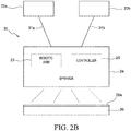
- FIG. 2B shows a block diagram outlining an aspect showing two thermoplastic polymer powder feedstocks and system 30 similar to system 20 shown in FIG. 2A , except that, as shown in FIG. 2B , system 30 comprises first and second thermoplastic polymer powder feedstock feedlines 31a and 31b in communication with the high-velocity sprayer 24 and the first and second thermoplastic polymer powder feedstocks 22a and 22b, respectively. That is, as shown in FIG. 2B , amounts of the first and second thermoplastic polymer powder feedstocks 22a, 22b are not mixed together to form a feedstock mixture. Instead, according to the aspect shown in FIG.
- FIG. 2B shows an optional robotic arm 23 (or "robot") that can be in communication with a controller 25. Controller 25 can further optionally be in communication with remote or integrated software or hardware, as desired, to control robotic arm movement as well as control flow rates and amounts of material deposited as a thermoplastic polymer coating 26a onto a substrate 26. Optionally, additional controllers (not shown) can be integrated into system 30 to control one or more aspects of system 30.
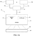
- FIG. 3A shows a block diagram outlining an aspect showing a thermoplastic polymer powder feedstock and a conductive powder feedstock and a system 40.
- a thermoplastic polymer powder feedstock 42a, and a conductive powder feedstock 42b are directed to a mixing vessel (not shown).
- the predetermined amounts of the first and second thermoplastic polymer feedstocks 42a, 42b are delivered via first and second thermoplastic polymer powder feedstock feedlines 41a and 41b, respectively, and mixed together to form a conductive thermoplastic polymer powder feedstock mixture 47.
- An amount of the conductive thermoplastic polymer powder feedstock mixture 47 is directed via conductive thermoplastic polymer powder feedstock mixture feedline 48 to high-velocity sprayer 44.
- Feedline 48 as shown in FIG. 3A is in communication with conductive thermoplastic feedstock mixture 47 and the high-velocity sprayer 44.
- Predetermined amounts of conductive thermoplastic polymer feedstock mixture 47 can be directed to the high-velocity sprayer 44 by any desirable means, including automated means regulated by a controller (not shown) and subject to, for example, software and hardware known to control, for example, feedstock flow rates from a supply to a sprayer, etc.
- the high-velocity sprayer 44 can be a thermal sprayer or a cold sprayer.
- the conductive thermoplastic polymer powder feedstock is converted by the high-velocity sprayer 44 into a conductive thermoplastic polymer coating 46a deposited onto substrate 46.
- FIG. 3A shows an optional robotic arm 43 (or “robot") that can be in communication with a controller 45.
- Controller 45 can further optionally be in communication with remote or integrated software or hardware, as desired, to control movement of the robotic arm 43 as well as control flow rates and amounts of deposited conductive thermoplastic polymer coating 46a onto a substrate 46.
- additional controllers can be integrated into system 40 to control one or more aspects of system 40.
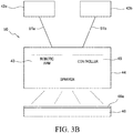
- FIG. 3B shows a block diagram outlining an aspect showing a conductive thermoplastic polymer powder and a system 50 similar to system 40 shown in FIG. 3A , except that as shown in FIG. 3B , system 50 comprises a thermoplastic polymer powder feedstock feedline 51a in communication with a thermoplastic polymer powder feedstock 42a and a high-velocity sprayer 44.
- Conductive powder feedstock feedline 51b is shown in communication with the conductive powder feedstock 42b and the high-velocity sprayer 44. That is, as shown in FIG. 3B , an amount of the thermoplastic polymer powder feedstock 42a is not mixed with an amount of the conductive powder feedstock 42b to form a conductive thermoplastic polymer feedstock mixture. Instead, according to an aspect shown in FIG.
- thermoplastic polymer powder feedstock 42a is directed to high-velocity sprayer 44 via thermoplastic polymer powder feedstock feedline 51a.
- conductive powder feedstock 42b is directed to the high-velocity sprayer 24 via conductive powder feedstock feedline 51b.
- FIG. 3B shows an optional robotic arm 43 (or “robot") that can be in communication with a controller 45. Controller 45 can further optionally be in communication with remote or integrated software or hardware, as desired, to control movement of the robotic arm 43 as well as control flow rates and amounts of deposited conductive thermoplastic polymer coating 46a onto a substrate 46.
- additional controllers can be integrated into system 50 to control one or more aspects of system 50.
- FIG. 4A shows a block diagram outlining an aspect showing a conductive thermoplastic polymer powder feedstock and a system 60 including mixing first and second thermoplastic polymer powder feedstocks with a conductive powder feedstock to form a conductive thermoplastic powder feedstock mixture, and then directing an amount of the conductive thermoplastic powder feedstock mixture to a high-velocity sprayer and depositing a conductive thermoplastic polymer coating onto a substrate surface.
- a conductive thermoplastic polymer powder feedstock and a system 60 including mixing first and second thermoplastic polymer powder feedstocks with a conductive powder feedstock to form a conductive thermoplastic powder feedstock mixture, and then directing an amount of the conductive thermoplastic powder feedstock mixture to a high-velocity sprayer and depositing a conductive thermoplastic polymer coating onto a substrate surface.
- an amount of a first thermoplastic polymer powder feedstock 62a, an amount of a second thermoplastic polymer powder feedstock 62b, and an amount of a conductive powder feedstock 62c are directed to a mixing vessel (not shown) and are mixed together to form a conductive thermoplastic polymer powder feedstock mixture 67.
- a desired amount of the conductive thermoplastic polymer powder feedstock mixture 67 is directed via feedstock mixture feedline 68 to high-velocity sprayer 64.
- Feedstock mixture feedline 68 as shown in FIG. 4A , is in communication with conductive thermoplastic polymer powder feedstock mixture 67 and the high-velocity sprayer 64.
- Predetermined amounts of: 1) the first thermoplastic polymer powder feedstock 62a; 2) the second thermoplastic polymer powder feedstock 62b; and 3) the conductive powder feedstock 62c are directed to the conductive thermoplastic polymer powder feedstock mixture 67 via first thermoplastic polymer powder feedstock feedline 61a, second thermoplastic polymer powder feedstock feedline 61b and conductive polymer powder feedstock feedline 61c, respectively, by any desirable means.
- Predetermined amounts of conductive thermoplastic polymer feedstock mixture 67 are directed to the high-velocity sprayer 64 by any desirable means, including, for example, an automated means regulated by a controller (not shown) and subject to, for example, software and hardware known to control, for example, feedstock flow rates to a sprayer, etc.
- the high-velocity sprayer 64 can be a thermal sprayer or a cold sprayer. As shown in FIG. 4A , the conductive thermoplastic polymer powder feedstock mixture 67 is converted by the high-velocity sprayer 44 into a conductive thermoplastic polymer coating 66a deposited onto substrate 46. While the high-velocity sprayer 64 can be operated manually, FIG. 4A shows an optional robotic arm 63 (or "robot") that can be in communication with a controller 65. Controller 65 can further optionally be in communication with remote or integrated software or hardware, as desired, to control movement of the robotic arm 63 as well as control flow rates and amounts of deposited conductive thermoplastic polymer coating 66a onto a substrate 66. Optionally, additional controllers (not shown) can be integrated into system 60 to control one or more aspects of system 60.
- FIG. 4B shows a block diagram outlining an aspect showing a conductive thermoplastic polymer powder and a system 70 similar to system 60 shown in FIG. 4A , except that as shown in FIG. 4B , system 70 comprises: 1) a first thermoplastic polymer powder feedstock feedline 71a in communication with the first thermoplastic polymer powder feedstock 62a and the high-velocity sprayer 64; 2) a second thermoplastic polymer powder feedstock feedline 71b in communication with the first thermoplastic polymer powder feedstock 62b and the high-velocity sprayer 64; and 3) a conductive powder feedstock feedline 71c in communication with the conductive powder feedstock 62c and the high-velocity sprayer 64. That is, as shown in FIG.
- an amount of the first thermoplastic polymer powder feedstock 62a, and an amount of the second thermoplastic polymer powder feedstock 62b are not mixed with an amount of the conductive powder feedstock to form a conductive thermoplastic polymer feedstock mixture. Instead, according to system 70 shown in FIG. 4B , a predetermined amount of the first thermoplastic polymer powder feedstock 62a is directed to high-velocity sprayer 64 via first thermoplastic polymer powder feedstock feedline 71a. Similarly, a predetermined amount of the second thermoplastic polymer powder feedstock 62b is directed to high-velocity sprayer 64 via second thermoplastic polymer powder feedstock feedline 71b.
- FIG. 4B shows an optional robotic arm 63 that can be in communication with a controller 65. Controller 65 can further optionally be in communication with remote or integrated software or hardware, as desired, to control movement of a robotic arm 63 (or “robot") as well as control flow rates and amounts of deposited conductive thermoplastic polymer coating 66a onto a substrate 66.
- controllers can be integrated into system 70 to control one or more aspects of system 70.
- the robotic arm disclosed above is equivalently referred to herein as a "robot", such that any feature of the robot (in addition to the "arm") can control the relative movement of the high-velocity sprayer, and/or the robot can control the direction of spray emitted from the high-velocity sprayer (e.g., the robot controls the direction and change the direction of spray from the high-velocity sprayer while the sprayer itself remains in a substantially stationary position, etc.).
- FIG. 5 is an illustration of an aircraft 80 having substrate surfaces and assemblies, sub-assemblies and components having substrate surfaces that can be advantageously coated by the thermoplastic polymer coatings and/or the conductive thermoplastic coatings set forth herein. It is further understood that, the coatings described herein can be advantageously coated onto substrates occurring on components, assemblies and sub-assemblies incorporated in further types of manned and unmanned aircraft, terrestrial vehicles, sub-surface and surface marine (e.g., water borne) vehicles, manned and unmanned satellites, etc.
- FIGs. 6-8 are flowcharts outlining aspects of the present disclosure.
- FIG. 6 outlines a method 100 comprising directing 102 at least one thermoplastic polymer powder to a high-velocity sprayer, followed by forming 104 a thermoplastic polymer spray formulation at or near the high-velocity sprayer.
- the method outlined in FIG. 6 further comprises directing 106 the thermoplastic spray formulation from the high-velocity sprayer to a substrate having a substrate surface, and forming 108 a thermoplastic polymer coating on the substrate surface.
- the method outlined in FIG. 6 is understood to at least relate to the systems shown in FIGs. 1 , 2A and 2B .
- FIG. 7 outlines a method 100 comprising directing 102 an amount of at least one thermoplastic polymer powder to a high-velocity sprayer, followed by directing 103 an amount of conductive powder to the high-velocity sprayer concurrently with thermoplastic polymer powder and forming 104a a conductive thermoplastic polymer spray formulation at or near the high velocity sprayer.
- the method further comprises directing 106a the conductive thermoplastic polymer spray formulation from the sprayer to a substrate surface, and forming 108a a conductive thermoplastic coating on the substrate surface.
- the method outlined in FIG. 7 is understood to at least relate to the systems shown in FIGs. 3A , 3B , 4A and 4B .
- FIG. 8 outlines a method 120 comprising directing 102a an amount of a first thermoplastic polymer powder and an amount of a second thermoplastic polymer powder and an amount of a conductive powder to a high-velocity sprayer, followed by forming 104a a conductive thermoplastic polymer spray formulation.
- the method further comprises directing 106a the conductive thermoplastic polymer formulation from the sprayer to a substrate surface, and forming 108a a conductive thermoplastic coating on the substrate surface.
- the method outlined in FIG. 8 is understood to at least relate to the systems shown in FIGs. 4A and 4B .
- FIG. 9 is an illustration of a first substrate and a second substrate, (equivalently referred to herein as first and second components or first and second parts) that are fastened together and, when sealed, a fillet seal is formed at the interface of the first substrate and second substrate (interface referred to equivalently herein as "juncture").
- Fillet seals are understood to occur two interfacing substrates (e.g., at the interface at or between to proximately located substrate surfaces, panels, etc.)
- the sealant applied to the area of the fillet seal effectively seals any gap or space at the interface.
- edge seals may be required to ameliorate an undesirable phenomenon known as "edge glow", when substrate material at edges of the substrate are exposed.
- Fiber-based materials e.g., for example, composite based materials that incorporate carbon fibers, boron fibers, aramid fibers, etc.
- edge glow can be particularly susceptible to "edge glow” as the exposed fiber ends at a component edge can behave as a cathode that emits electrons to a degree that can approximate the electrical energy of a weak spark.
- an assembly 130 comprises a first substrate 132 and a second substrate 134 that are joined (e.g., fastened together via fasteners 136). As shown in FIG. 9 , the first 132 and second 134 substrates are joined in an overlapping orientation to form a lap joint.
- thermoplastic polymer sealant 137 (that can also comprise an amount of conductive material for the purpose of delivering a predetermined resistivity to the thermoplastic polymer coating) is applied to the first 132 and second 134 substrates, such that a fillet seal 138 is formed at the first substrate 132 and second substrate 134 interface 139.
- first substrate edge 132a, and a portion of second substrate edge 134a are also coated with the thermoplastic polymer coating 137 (that can also comprise a predetermined amount of conductive material for the purpose of delivering a predetermined and tailored resistivity value to the thermoplastic polymer coating) to form a first substrate edge seal 132b and a second substrate edge seal 134b.
- FIGs. 10 and 11 are illustrations of a portion of an aircraft fuel tank interior 140 showing a first substrate 142 oriented proximate to a second substrate 144. As shown in FIGs. 10 and 11 , the first substrate 142 is fastened to the second substrate 144 via fasteners 146.
- a thermoplastic polymer sealant 147 (that can also comprise a predetermined amount of conductive material for the purpose of delivering a predetermined and tailored resistivity value to the thermoplastic polymer coating) is applied to the first 142 and second 144 substrates, such that a fillet seal 148 is formed at the substrate interface 149 located at the juncture of the first substrate 142 and second substrate 144. Though not shown in FIGs.
- the sealant material 147 could obtain an edge seal at the exposed edge of the first and/or second substrates 142, 144. That is, if either of the first and/or second substrates 142, 144 comprise a fiber-based or other material that could be susceptible to "edge glow" in the presence of a charge (e.g., an electrical charge caused by or resulting from an EME, etc.), the thermoplastic polymer sealant 147 can be applied to achieve the required edge seals at the edges of first and or second substrates 142, 144.
- a charge e.g., an electrical charge caused by or resulting from an EME, etc.
- FIG. 12 is an illustration of n aircraft fuel tank interior 150 showing a first substrate 152 oriented proximate to a second substrate 154. As shown in FIG. 12 , the first substrate 152 is fastened to the second substrate 154 via fasteners 156.
- a thermoplastic polymer sealant 157 (that can also comprise a predetermined amount of conductive material for the purpose of delivering a predetermined and tailored resistivity value to the thermoplastic polymer coating) is applied to the first 152 and second 154 substrates, such that a fillet seal 158 is formed at the substrate interface 159 located at the juncture of the first substrate 152 and second substrate 154. Though not specifically shown in FIG.
- the sealant material 157 could obtain an edge seal at the exposed edge of the first and/or second substrates 152, 154. That is, if either of the first and/or second substrates 152, 154 comprise a fiber-based or other material that could be susceptible to "edge glow" in the presence of a charge (e.g., an electrical charge caused by or resulting from an EME, etc.), the thermoplastic polymer sealant 157 can be applied to achieve the required edge seals at the edges of first and or second substrates 152, 154.
- a charge e.g., an electrical charge caused by or resulting from an EME, etc.
- first substrate materials are made from a material having a resistivity value that differs from the resistivity value of the second substrate, and where the two substrates are joined together, or are otherwise in close proximal contact
- the variance in resistivities can result in damage at such junctures when EMEs occur (e.g., resulting from static discharge and/or lightning strikes), or at the substrate edges.
- the conductive thermoplastic polymer sealant materials e.g.
- sealants equivalently referred to herein as the "sealants" and seals placed as fillet seals between such first and second structures and/or as end seals on such structures, as well as seals placed as edge seals at first and/or second substrate edges ameliorate or eliminate deleterious effects and damage otherwise caused by EMEs.
- seals and sealants disclosed herein afford many advantages over non-thermoplastic sealants presently used in the manufacture of sub-assemblies and assemblies that house or otherwise become exposed to harsh environmental factors and the presence of chemicals, solvents, fuels, etc. (e.g., fuel tank, etc.).
- substrate materials have similar resistivies to one another and can allow static or other electrical charges to pass freely and without incident from structure to structure
- thermoplastic seals and thermoplastic sealant materials disclosed herein that do not have a conductive component still allow for improved sealing processes and improved seals and sealants as compared to known sealants and sealant materials used, for example, in the manufacture of enclosed environments, including, without limitation, assemblies such as fuel tanks, and aircraft fuel tanks., etc.
- thermoplastic polymer powder feedstock is "doped" with a predetermined amount of conductive powder to form a conductive thermoplastic polymer powder feedstock.
- the powder comprising particles is subjected to heat and/or high velocity via gas jets to at least soften and deform the particles in the conductive thermoplastic polymer powder feedstock.
- the particles leave the sprayer as a particulate spray at a predetermined velocity and impact a desired target such as, for example, the areas where fillet seals and edge seals on a substrate or substrates are required.
- a desired target such as, for example, the areas where fillet seals and edge seals on a substrate or substrates are required.
- the particulate spray forms a thermoplastic polymer coating, or thermoplastic polymer sealant, on the substrates and forms a thermoplastic polymer seal.
- the resistivity value of the thermoplastic polymer seals formed by the presently disclosed sealants formed can be tailored or "tuned" to a desired resistivity value.
- EME electromagnetic effect
- the conductivity of the thermoplastic polymer sealant and seals will at least ameliorate deleterious effects from the EME that would otherwise be encountered at or near the fillet seals occurring at or near the substrate interfaces (e.g., adjoined structures), and at substrate material edge seals.
- FIG. 13 is a flowchart outlining a method according to aspects of the present disclosure, with the method 200 including, delivering 202 at least one thermoplastic polymer powder feedstock to a high-velocity sprayer.
- the thermoplastic polymer powder feedstock includes at least one of polyetheretherketone, polyetherketoneketone, polyamide, polyphenylsulfide, polyphenylsulfone, polysulfone, and polyetheramide.
- the thermoplastic polymer powder feedstock can include at least one of copolymers including Hytrel® TPC-ET (DuPont®), thermoplastic elastomers, and thermoplastic fluoroelastomers including DAI-EL® T-530 (Daikin®).
- the disclosed method further includes forming 204 a thermoplastic polymer sealant material and directing 206 the thermoplastic polymer sealant material from the high-velocity sprayer to a substrate surface, and depositing 208 an amount of the thermoplastic polymer sealant material onto the substrate to form a thermoplastic polymer seal.
- the method outlined in FIG. 13 can be used to form the thermoplastic polymer material sealant and the resulting seals formed therefrom as shown in any one or more of FIGs. 1 through FIG. 12 .
- FIG. 14 is a flowchart outlining a further method according to aspects of the present disclosure, with the method 300 including, delivering 202 at least one thermoplastic polymer powder feedstock to a high-velocity sprayer.
- the thermoplastic polymer powder feedstock includes at least one of polyetheretherketone, polyetherketoneketone, polyamide, polyphenylsulfide, polyphenylsulfone, polysulfone, and polyetheramide.
- the thermoplastic polymer powder feedstock can include at least one of copolymers including Hytrel® TPC-ET (DuPont®), thermoplastic elastomers, and thermoplastic fluoroelastomers including DAI-EL® T-530 (Daikin®).
- the disclosed method further includes forming 204 a thermoplastic polymer sealant material and directing 206 the thermoplastic polymer sealant material from the high-velocity sprayer to a substrate surface, and depositing 208 an amount of the thermoplastic polymer sealant onto the substrate to form a thermoplastic polymer seal.
- the method 300 further includes directing 210 movement of the high-velocity sprayer with the movement directed by a robot, equivalently referred to herein as a "robot arm” or "robotic structure”.
- the robot is in communication with the high-velocity sprayer and the robot is further in communication with a controller.
- the method outlined in FIG. 14 can be used to form the thermoplastic polymer material, sealants and the resulting seals formed therefrom as disclosed in any one or more of FIGs. 1 through FIG. 13 .
- FIG. 15 is a flowchart outlining a methods according to aspects of the present disclosure, with the method 400 including, delivering 402 at least one thermoplastic polymer powder feedstock to a high-velocity sprayer.
- the thermoplastic polymer powder feedstock includes at least one of polyetheretherketone, polyetherketoneketone, polyamide, polyphenylsulfide, polyphenylsulfone, polysulfone, and polyetheramide.
- the thermoplastic polymer powder feedstock can include at least one of copolymers including Hytrel® TPC-ET (DuPont®), thermoplastic elastomers, and thermoplastic fluoroelastomers including DAI-EL® T-530 (Daikin®).
- the disclosed method further includes delivering 404 a conductive powder feedstock to the high-velocity sprayer, forming 406 a thermoplastic polymer sealant material and directing 408 the thermoplastic polymer sealant material from the high-velocity sprayer to a substrate surface, and depositing 410 an amount of the thermoplastic polymer sealant onto the substrate to form a thermoplastic polymer seal.
- the method outlined in FIG. 15 can be used to form the thermoplastic polymer material and sealants and the seals formed therefrom as shown in any one or more of FIGs. 1 through FIG. 14 .
- FIG. 16 is a flowchart outlining a methods according to aspects of the present disclosure, with the method 400 including, delivering 402 at least one thermoplastic polymer powder feedstock to a high-velocity sprayer.
- the thermoplastic polymer powder feedstock includes at least one of polyetheretherketone, polyetherketoneketone, polyamide, polyphenylsulfide, polyphenylsulfone, polysulfone, and polyetheramide.
- the thermoplastic polymer powder feedstock can include at least one of copolymers including Hytrel® TPC-ET (DuPont®), thermoplastic elastomers, and thermoplastic fluoroelastomers including DAI-EL® T-530 (Daikin®).
- the disclosed method further includes delivering 404 a conductive powder feedstock to the high-velocity sprayer, forming 206 a thermoplastic polymer sealant material and directing 408 the thermoplastic polymer sealant material from the high-velocity sprayer to a substrate surface, and depositing 410 an amount of the thermoplastic polymer sealant onto the substrate to form a thermoplastic polymer seal.
- the method 400 further includes directing 412movement of the high-velocity sprayer with the movement directed by a robot structure in communication with the high-velocity sprayer and with the robot structure further in communication with a controller.
- the method outlined in FIG. 15 can be used to form the thermoplastic polymer material and sealants as shown in any one or more of FIGs. 1 through FIG. 14 .
- an amount of 95 g of PEEK powder (KetaSpire® KT820, low melt flow; KetaSpire® KT-880, high melt flow - Spire Ultra Polymers, Solvay, Brussels Belgium) having a median particle size of about 30 ⁇ m was mixed with an amount of 5 g of conductive titanium powder (TS1374 - Titanium Powder - Stanford Advanced Materials, Irvine, CA) having a nominal particle diameter of about 90 ⁇ m.
- the two powders were mixed using a Mazerustar Mixer (Medisca, LasVegas, NV), to form a thorough conductive thermoplastic polymer powder mixture produced by the combining of the two powders (representing 100% by weight).
- the mixture was loaded as a feedstock into a reservoir of a thermal sprayer (ASC PG-550 (Alamo Supply Co., Lt., Houston, TX)
- ASC PG-550 Alamo Supply Co., Lt., Houston, TX
- Three formulations having a varied amount (% by volume) of titanium in the total powder mixture were prepared: 1) 1 % titanium powder by volume; 2) 6% titanium by volume; and 3) 9% titanium by volume.
- the thermal sprayer was set to a flow rate equal to approximately 1 to 50 g/sec., and amounts of the three feedstock mixtures (conductive thermoplastic polymer powder mixtures) prepared in Example 1 were each directed from the reservoir into the thermal sprayer and to the heated spray head. Each feedstock achieved a phase change, from solid to a flowing, heated sprayable liquid, and was then sprayed as a particulate spray and directed by and from the thermal sprayer to a substrate surface comprising a lap joint interface of an aluminum panel (2000, 6000 and 7000 series aluminum) located proximate to a carbon fiber reinforced plastic composite panel. The substrate surface was solvent cleaned (acetone wipe) and dried completely. The head of the thermal sprayer was located at a distance of about 24" from the substrate surface. The thermal sprayer was moved manually to deposit a visually uniform coverage of the substrate surface. The substrate surface temperature was monitored with a thermostat.
- the conductive thermoplastic coatings prepared and deposited according to the processes described in Examples 1 and 2 were allowed to cool on the substrate surface for not more than 5 minutes.
- the conductive thermoplastic coating had measured resistivity values as set forth in Table 1 for three Samples (#1, #2, and #3) having 1%, 6% and 9% by volume of titanium in the conductive thermoplastic polymer powder formulations prepared. Adjusting the amount/concentration/ratio of conductive titanium powder in the thermoplastic polymer (PEEK/Ti) powder feedstock mixture resulted in a measured variance in the resistivity of the conductive thermoplastic polymer coating as noted in Table 1.
- thermoplastic polymer powders were mixed with varying amounts of conductive powders to produce feedstock mixtures as described above.
- thermoplastic polymer sealants and seals and conductive thermoplastic polymer sealants and seals contemplate thermoplastic polymer sealants and seals and conductive thermoplastic polymer sealants and seals, and methods of their delivery to substrates and substrate surfaces comprising such sealants and seals), as well as components and assemblies comprising such thermoplastic polymer and conductive thermoplastic polymer sealants and seals, and larger structures and object comprising components and assemblies that comprise the disclosed thermoplastic polymer and conductive thermoplastic polymer sealants and seals, including, for example and without limitation, vehicles, including aircraft.
- Such contemplated components, assemblies etc. include, without limitation, seals found required for installing, securing, etc. components, assemblies, etc. associated with aircraft (e.g. spars, ribs, stringers, etc.), with such components finding particular utility in connection with vehicle fuel tanks and fuel tank systems.
- Such vehicles include, without limitation, a manned aircraft, an unmanned aircraft, a manned spacecraft, an unmanned spacecraft, a manned rotorcraft, an unmanned rotorcraft, a satellite, a rocket, a manned terrestrial vehicle, an unmanned terrestrial vehicle, a manned and unmanned hovercraft, a manned surface water borne vehicle, an unmanned surface water borne vehicle, a manned sub-surface water borne vehicle, an unmanned sub-surface water borne vehicle, and combinations thereof.
Landscapes
- Chemical & Material Sciences (AREA)
- Engineering & Computer Science (AREA)
- Materials Engineering (AREA)
- Organic Chemistry (AREA)
- Life Sciences & Earth Sciences (AREA)
- Wood Science & Technology (AREA)
- Chemical Kinetics & Catalysis (AREA)
- Mechanical Engineering (AREA)
- Plasma & Fusion (AREA)
- Physics & Mathematics (AREA)
- Metallurgy (AREA)
- Composite Materials (AREA)
- Application Of Or Painting With Fluid Materials (AREA)
- Sealing Material Composition (AREA)
Abstract
Description
- The present disclosure relates generally to the field of coatings and sealants. More specifically the present disclosure relates to the field of coatings and sealants, including conductive coatings and sealants, particularly those coatings and sealants applied to a surface by thermal spraying.
- In many fields, components on large structures, including those found on vehicles, including aircraft, etc., are typically coated with paints, primers, coatings, etc. that can provide a number of important functions to a substrate surface, including, for example, protection from corrosion and other forms of environmental degradation, overcoat or sealant adhesion, abrasion resistance, appearance, etc. Coating and sealants are often applied to areas of assembled components or sub-assemblies that are difficult to access through traditional coating and sealant application processes. In addition, a significant number, sometimes numbering in the thousands and tens of thousands, of small parts (e.g., fasteners, etc.) and areas requiring sealing (e.g., edge seals and fillet seals, etc.) requiring coatings and/or sealants can occur in assemblies in a large structure (e.g., fuel tanks on aircraft, etc.). Further, many coatings and sealants require lengthy curing protocols, or require applying heat or other added triggering mechanism (e.g. ultraviolet radiation, etc.) to obtain an appropriate degree of curing.
- Further, some coatings (e.g. paints and primers, etc.) and sealants are often electrically insulative and can result in an impediment to the dissipation of static and other electrical charges.
- However, certain structures require the need to dissipate electrical charges that build up on a structure's interior and/or exterior surfaces, including static electrical charges, and charges resulting from, for example lightning strikes, etc. The need for electrical charge dissipation is increasingly important in the aircraft industry, as aircraft manufacture continues to incorporate non-metallic materials. Further, in certain aircraft assemblies, non-metallic materials, such as composites, plastics, etc., that do not dissipate electrical charges predictably across their surfaces may be joined with, or otherwise contact, assemblies and sub-assemblies that comprise metallic materials that do conduct electrical charges. That is, components, assemblies and sub-assemblies that include both composite and metallic materials may be used in the manufacture of, or otherwise incorporated into, larger structures (e.g. aircraft).
- Such structures may encounter electromagnetic effects (EMEs) including, for example, and without limitation, lightning strikes. When a structure encounters an EME, the charge delivered to the structure travels throughout any conductive path, and can cause damage to exposed dielectric materials including, for example, composite materials. The electrical damage to composite materials from EMEs can be exacerbated if the edges of the composite material comprise exposed carbon fibers. If the path of charges resulting from an EME encounters varying materials having varying conductivities, damage at or near the material interface can occur. Such interfaces include, without limitation, fasteners/substrate interfaces, and can further include joined interfaces where, for example, seals (e.g., fillet seals, edge seals etc.) occur.
- Carbon fiber reinforced plastic materials (CFRPs) have utility in structures including, without limitation, vehicles including, without limitation, aircraft. CFRPs comprise a fiber material (e.g. carbon fibers, etc.) impregnated with a resin material (e.g. epoxy resin, acrylic resin, etc.) to make so-called prepregs. Prepregs are partially cured layers that can be manufactured into rolls that can yield unrolled sheets for use in composite material manufacture. Prepreg material, or "prepregs" can then be "laid-up" or "stacked" into multi-layered "stacks" that can be shaped on forming mandrels or other tooling, followed by curing or partially curing the shaped material to produce a composite material that, if desired, adopts desired and predetermined shapes and dimensions imparted by the tool, with the composite material having desired weight and strength. Alternately, prepregs may be oriented into a stack that is trimmed and cured to form a solid stack for use as a composite material structure or other type of composite component.
- In aircraft manufacture, CFRP parts are often joined to other CFRP parts as well as other metallic parts and non-metallic parts. Problems can occur with respect to predictably dissipating electrical charges when materials, such as CFRPs and various metals (e.g. aluminum, titanium, etc.) that have differing conductivities are joined, fastened, or are otherwise in close proximity to one another. Such interfaces can sustain EME damage in the course of EME events such as, for example, static discharge and/or lightning strikes where electrical current builds up and is not dispersed efficiently due to the presence of materials having differing conductivities/resistivities, as electrical charges move along a pathway. This is especially problematic at component interfaces where two materials are joined or in contact with one another and the materials have varying resistivity values (e.g., where a first substrate/component/part is made from a conductive material and is joined to or positioned proximate to a second substrate/component/part made from a non-conductive material or a material with a significantly different conductivity/resistivity as compared to the first substrate/component/part.
- Coatings, especially coatings used in aircraft manufacture, also must be robust enough to possess a plurality of characteristics, but may not adequately provide all of the required functions to an equivalent or acceptable degree. For example, conductive coatings for dissipating electrical charges across metallic and non-metallic coatings alike have been tried with varying success.
- However, the known conductive coatings must be loaded with conductive particles to such an extent (sometimes as much as 50-70 weight percent), that other required coating characteristics suffer. Further, such heavily loaded conductive coatings can make certain coating application techniques difficult or impossible (e.g., high viscosity coating materials cannot be applied using, for example, spray techniques, etc.).
- In addition, surface coatings that may be designed to alleviate electrical imbalances across various metallic and/or non-metallic surfaces must often, at least in part, address additional concerns and functions including appearance, adhesion, abrasion resistance, environmental degradation, etc.
- Further, inherent coating characteristics (viscosity, etc.,) may make it difficult to apply such coatings to restrictive locations and surfaces using efficient application techniques. For example, an otherwise desirable coating may be too viscous to apply to a surface using sprayers, when an application mode such as spraying could otherwise offer improvements to coating processing in terms of, efficiency, cost savings, etc.
- In addition, specialized coatings having a useful range of varying properties may be expensive to prepare, maintain, store, or deploy. Otherwise useful coatings may further have long curing times, for example taking days to cure with or without the presence of elevated curing temperatures or the use of additional triggering processes. Such extended or complex curing regimens further add to the manufacturing time required, as well as increasing cost. In addition, specialized coatings may lack an adequate shelf life or pot life to be useful for very long on-site.
- It may further be economically impractical for a particular manufacturing facility (in terms of equipment or space requirements) to store and/or inventory coatings that require, for example, maintenance at particular temperatures.
- A present aspect discloses an assembly including a first substrate and a second substrate, with the first substrate including a first substrate edge and the second substrate including a second substrate edge. The second substrate is located or otherwise oriented proximate to the first substrate to form a substrate interface at a juncture between the first substrate and the second substrate. A spray-deposited thermoplastic polymer sealant is configured to form a thermoplastic polymer seal. According to further aspects, the thermoplastic polymer seal comprises at least one of a fillet seal located at the substrate interface between the first and second substrates and an edge seal located at the first and second substrate edges.
- In another aspect, the thermoplastic polymer sealant material includes at least one thermoplastic polymer comprising at least one of: nylon, polyetheretherketone, polyetherketoneketone, polyamide, polyphenylsulfide, polyphenylsulfone, polysulfone, and polyetheramide. The spray-deposited thermoplastic polymer sealant material further includes at least one thermoplastic polymer comprising at least one of: copolymers including Hytrel® TPC-ET (DuPont®), thermoplastic elastomers, and thermoplastic fluoroelastomers including DAI-EL® T-530 (Daikin®).
- In another aspect, the assembly includes a thermoplastic polymer sealant that further includes a conductive material comprising at least one of: titanium, nickel alloy, copper, carbon black, graphene powder, and carbon nanotubes.
- Another present aspect discloses a spray-deposited thermoplastic polymer sealant, with the sealant including at least one thermoplastic polymer. The at least one thermoplastic polymer includes at least one of: nylon, polyetheretherketone, polyetherketoneketone, polyamide, polyphenylsulfide, polyphenylsulfone, polysulfone, and polyetheramide. Further thermoplastic polymers include at least one thermoplastic polymer powder comprising at least one of: copolymers including Hytrel® TPC-ET (DuPont®), thermoplastic elastomers, and thermoplastic fluoroelastomers including DAI-EL® T-530 (Daikin®).
- In another aspect, the thermoplastic sealant further includes a conductive material comprising at least one of: titanium, nickel alloy, copper, carbon black, graphene powder, or carbon nanotubes. Still further aspects are directed to a method for depositing a sealant to a substrate surface, with the method including delivering at least one thermoplastic polymer powder feedstock material to a high-velocity sprayer. The at least one thermoplastic polymer powder feedstock material includes at least one of: nylon, polyetheretherketone (PEEK), polyetherketoneketone (PEEK), polyamide, polyphenylsulfide, polyphenylsulfone, polysulfone, and polyetheramide. Further thermoplastic polymer powder feedstocks include at least one thermoplastic polymer powder comprising at least one of: copolymers including Hytrel® TPC-ET (DuPont®), thermoplastic elastomers, and thermoplastic fluoroelastomers including DAI-EL® T-530 (Daikin®).The thermoplastic polymer forms a thermoplastic polymer sealant material that is then directed from the high-velocity sprayer to a substrate surface, and an amount of the thermoplastic polymer sealant material is deposited onto the substrate surface to form a thermoplastic seal. The thermoplastic sealant is deposited onto the substrate to an average thickness ranging from about 10 µm to about 2000 µm.
- In a further aspect, the thermoplastic sealant is deposited onto at least one substrate at a deposition rate ranging from about 20 µm on 1 ft2 in 10 seconds, or greater.
- In a further aspect, the thermoplastic sealant is deposited onto at least one substrate at a deposition rate ranging from about 1 gram/second to about 50 grams/second.
- In a further aspect, the high-velocity sprayer is a thermal sprayer that can be a flame sprayer or cold sprayer.
- In another aspect, according to a further method, in the step of directing the thermoplastic polymer powder from the high-velocity sprayer to the substrate surface, the method further includes directing movement of the high-velocity sprayer with the movement controlled by a robot or "robotic structure" in communication the high-velocity sprayer, and the robot further in communication with a controller, and controlling the amount of conductive thermoplastic sealant material applied to a substrate, substrate surfaces and substrate surface interfaces.
- In a further aspect, according to a further method, a conductive material is also delivered, to the high-velocity sprayer along with or substantially concurrently with the delivery of the thermoplastic polymer powder to the high-velocity sprayer, with the conductive material including a conductive material powder comprising at least one of: titanium, nickel alloy, carbon black or carbon nanotubes. An amount of the conductive material is deposited with the thermoplastic polymer onto the substrate surface to form a conductive thermoplastic sealant. In a further aspect, the conductive thermoplastic sealant deposited onto the substrate surface has a resistivity ranging from about 1x10⁵ to about 1x10¹¹ ohm-m, and preferably from about 1x10⁵ to about 1x10⁸ ohm-m.
- In another aspect, the first thermoplastic polymer powder feedstock and the conductive material powder feedstock are combined into a powder mixture feedstock that is then delivered to the high-velocity sprayer. In a further aspect, the high-velocity sprayer is a thermal sprayer or a cool sprayer. According to another aspect, the conductive material powder feedstock can be provided to the high-velocity sprayer substantially concurrently or substantially simultaneously with the delivery to the high-velocity sprayer of the first thermoplastic polymer powder feedstock, or the feedstocks can be delivered to a high-velocity sprayer according to a programmed delivery via one or more feedstock feedlines.
- In another aspect, and according to a further method, a second material in powder form is delivered to the high velocity sprayer, with the second material including at least one second thermoplastic polymer powder feedstock. The second thermoplastic polymer powder feedstock includes at least one of: nylon, polyetheretherketone, polyetherketoneketone, polyamide, polyphenylsulfide, polyphenylsulfone, polysulfone, and polyetheramide. Further thermoplastic polymer powder feedstocks include at least one thermoplastic polymer powder comprising at least one of: copolymers including Hytrel® TPC-ET (DuPont®), thermoplastic elastomers, and thermoplastic fluoroelastomers including DAI-EL® T-530 (Daikin®).The second thermoplastic polymer powder feedstock can be provided to the sprayer substantially concurrently or substantially simultaneously with the delivery to the sprayer of the first thermoplastic polymer powder feedstock, or the two or more feedstocks can be delivered to the sprayer via one or more feedstock feedlines according to a predetermined sequence controlled by a controller and/or a programmed sequencer.
- In another aspect, according to a further method, a conductive powder feedstock material is also delivered to the high-velocity sprayer along with the first thermoplastic polymer powder feedstock and the second thermoplastic polymer powder feedstock, with the conductive powder feedstock including at least one of: titanium, nickel, copper, carbon black, graphene powder, or carbon nanotubes. An amount of the conductive powder feedstock material is deposited with the first and second thermoplastic polymer feedstocks onto the substrate surface to form a conductive thermoplastic sealant. In a further aspect, the conductive thermoplastic sealant deposited onto the substrate surface has a resistivity ranging from about 1x10⁵ to about 1x10¹¹ ohm-m, and preferably from about 1x10⁵ to about 1x10⁸ ohm-m.
- In another aspect, the conductive powder feedstock and at least one of the first thermoplastic polymer powder feedstock and the second thermoplastic polymer powder feedstock are combined into a powder feedstock mixture that is then delivered to the high- velocity sprayer. In a further aspect, the high-velocity sprayer is a thermal sprayer or a cool sprayer. According to another aspect, the conductive material powder can be provided to the sprayer substantially concurrently or substantially simultaneously with the delivery to the sprayer of the first thermoplastic polymer powder, or the two or more feedstocks can be delivered to the sprayer via one or more feedstock feedlines according to a predetermined sequence controlled by a controller and/or a programmed sequencer.
- The features, functions and advantages that have been discussed can be achieved independently in various aspects or may be combined in yet other aspects, further details of which can be seen with reference to the following description and the drawings.
- Having thus described variations of the disclosure in general terms, reference will now be made to the accompanying drawings, which are not necessarily drawn to scale, and wherein:
-
FIG. 1 is an illustration of an aspect of the present disclosure showing a thermoplastic polymer powder feedstock and a system including the thermoplastic polymer powder feedstock and a high-velocity sprayer for depositing a thermoplastic polymer coating onto a substrate surface; -
FIG. 2A is an illustration of an aspect of the present disclosure showing the mixing of more than one thermoplastic polymer powder feedstocks to form a thermoplastic powder feedstock mixture for use as a spray formulation, and a system including the thermoplastic powder feedstock mixture and a high-velocity sprayer for depositing a tunable thermoplastic polymer coating onto a substrate surface; -
FIG. 2B is an illustration of an aspect of the present disclosure showing a plurality of thermoplastic powder feedstocks delivered via separate feedlines to the sprayer shown inFIG. 2A , and a system for depositing a tunable thermoplastic polymer coating onto a substrate surface; -
FIG. 3A is an illustration of an aspect of the present disclosure showing at least one thermoplastic polymer powder feedstock mixed with at least one conductive powder feedstock to form a conductive thermoplastic powder feedstock mixture, and a system including the conductive thermoplastic polymer powder feedstock mixture and a high-velocity sprayer for depositing a conductive thermoplastic polymer coating onto a substrate surface; -
FIG. 3B is an illustration of an aspect of the present disclosure showing at least one thermoplastic polymer powder feedstock and a conductive powder feedstock shown inFIG. 3A , and a system including a high-velocity sprayer for depositing a conductive thermoplastic polymer coating onto a substrate surface, with more than one thermoplastic polymer powder feedstock and the one or more conductive powder feedstock delivered or directed to the sprayer via separate feed lines; -
FIG. 4A is an illustration of an aspect of the present disclosure showing more than one thermoplastic polymer powder feedstocks mixed with a conductive powder feedstock to form a conductive thermoplastic powder feedstock mixture, and a system including the conductive thermoplastic polymer powder feedstock mixture and a high-velocity sprayer for depositing a conductive thermoplastic polymer coating onto a substrate surface; -
FIG. 4B is an illustration of an aspect of the present disclosure showing two different thermoplastic polymer powder feedstocks and a conductive powder feedstock shown inFIG. 4A , and a system including the two different thermoplastic polymer powder feedstocks, the conductive powder feedstock and a high-velocity sprayer for depositing a conductive thermoplastic polymer coating onto a substrate surface, with the two thermoplastic polymer powder feedstocks and the conductive powder feedstock delivered or directed to the sprayer via separate feed lines; -
FIG. 5 is an illustration of an aircraft; -
FIG. 6 is a flowchart outing a method according to aspects of the present disclosure; -
FIG. 7 is a flowchart outing a method according to aspects of the present disclosure; and -
FIG. 8 is a flowchart outing a method according to aspects of the present disclosure. -
FIG. 9 is an illustration of two parts, or substrates fastened together and forming fillet seals at their juncture and having fillet seals and edge seals with sealant applied according to aspects of the present disclosure; -
FIG. 10 is an illustration of a fillet seal with a sealant applied according to an aspect of the present disclosure; -
FIG. 11 is an illustration of a fillet seal with a sealant applied according to an aspect of the present disclosure; -
FIG. 12 is an illustration of a fillet seal with a sealant applied according to an aspect of the present disclosure; -
FIG. 13 is a flowchart outlining methods according to aspects of the present disclosure; -
FIG. 14 is a flowchart outlining methods according to aspects of the present disclosure; -
FIG. 15 is a flowchart outlining methods according to aspects of the present disclosure; and -
FIG. 16 is a flowchart outlining methods according to aspects of the present disclosure. - Aspects of the present disclosure are directed to powdered thermoplastic formulations that can be tunable, or otherwise have their characteristics changed in real time during deposition and that can include conductive materials and that can also be conductively tunable. The powdered thermoplastic polymer feedstocks can include at least one conductive powdered material to form a conductive thermoplastic powder feedstock mixture that can be deposited onto a substrate surface via a high-velocity sprayer to form a tunable conductive thermoplastic coating on a substrate surface, with the conductive thermoplastic coating having predetermined characteristics.
- Aspects of disclosed thermoplastic polymer powder powdered conductive coating formulations can be tuned or tailored, including in real time, to provide a wide range of required coating characteristics, while also providing robust protective coating qualities to the substrates being coated with the presently disclosed thermoplastic coatings.
- According to further aspects, powdered conductive thermoplastic polymer coating formulations (that contain a conductive powder) can be tuned or tailored, including in real time, and provide a wide range of required characteristics for electrically conductive thermoplastic coatings offering a particular, and wide-ranging amount of resistivity or conductivity, while also providing robust protective qualities to the substrates being coated with the presently disclosed conductive thermoplastic coatings.
- Additionally, aspects of the present disclosure are directed to thermoplastic polymer powder coating formulations that can be tailored as precursor feedstock mixtures, or that can be delivered substantially concurrently or in predetermined sequence to a sprayer (e.g., a predetermined programmed sequence) from separate feedstock sources or supplies to a high velocity sprayer. The sprayer then delivers the thermoplastic polymer powder coating formulations to form a thermoplastic coating, using high-velocity spraying techniques, to metallic and/or non-metallic substrates and components, with the thermoplastic coatings having predetermined characteristics that can be tuned in real time (e.g., in real time during application to a substrate surface, etc.). When a conductive powdered feedstock material is present in the thermoplastic polymer powder feedstock, various characteristics of the resulting applied conductive thermoplastic coatings can be predictably tailored, even in substantially real-time, by changing the proportions of powdered feedstock constituents (e.g., the proportion(s) of the at least one thermoplastic polymer powder feedstock and the conductive powder feedstock) that are provided to the sprayer.
- 'Young's (elastic) modulus' is a well known term in the art in relation to thermoplastic polymer sealants. Young's modulus may be measured, for example, according to ASTM D638-14 - Standard Test Method for Tensile Properties of Plastics.
- 'Resistivity value' is a well known term in the art in relation to thermoplastic polymer sealants.
- The resistivity value may be measured, for example, according to ASTM D257-07 - Standard Test Methods for DC Resistance or Conductance of Insulation Materials.
- Without being limiting, the average particle size of the thermoplastic polymer powder feedstock(s) used according to aspects of the present disclosure range from about 20 µm to about 300 µm. In addition, without being limiting, the average particle size of the conductive powder feedstock(s) used according to aspects of the present disclosure range from about 5 µm to about 80 µm. The high-velocity sprayers used in connection with aspects of the present disclosure include sprayers able to disperse a feedstock at velocities ranging from about 20 m/s to about 1200 m/s. Such sprayers include thermal (e.g., flame sprayers, etc.) and cold sprayers. 'Average particle size' is a well known term in the art. Average particle size may, for example, be determined using standard methods including the use of particle sizing analyzers that employ laser diffraction (Beckman Coulter Life Sciences, Indianapolis, IN.). Accordingly, average particle size may refer to Dv50 (the median for a volume distribution). Average particle size may be measured, for example, according to ASTM E2651 - Standard Guide for Powder Particle Size Analysis.
- According to one aspect, the thermoplastic polymer powder feedstock comprises at least one of a nylon, polyetheretherketone (equivalently referred to as PEEK), polyetherketoneketone (equivalently referred to as PEKK), polyamide, polyphenylsulfide, polyphenylsulfone, polysulfone, and polyetheramide. Further thermoplastic polymer powder feedstocks include at least one thermoplastic polymer powder comprising at least one of: copolymers including Hytrel® TPC-ET (DuPont®), thermoplastic elastomers, and thermoplastic fluoroelastomers including DAI-EL® T-530 (Daikin®).
- In further aspects, the thermoplastic polymer powder feedstock comprises at least one of a thermoplastic polyester elastomer powder or a thermoplastic fluoroelastomer powder.
- Contemplated thermoplastic elastomer powders include those that can be obtained as PEEK, PEKK, Hytrel® 5526 (DuPont); Dai-El™, (Daikin®); Hipex®, (Kraiburg), etc. The thermoplastic polymer powder feedstocks preferably have an average particle size ranging from about 20 µm to about 300 µm.
- Polyether ether ketone (PEEK) is an organic thermoplastic in the polyaryletherketone (PAEK) family, with PEEK having the general formula:

- PEEK has a coefficient of thermal expansion value (depending upon grade) ranging from of about 20 to about 80 ppm/°F (i.e. about 2 to about 8 x 10⁻⁵ in./in/°F), a Young's modulus value of about 3.6 GPa and a tensile strength ranging from about 90 MPa to about 100 MPa. PEEK is highly resistant to thermal degradation as well as attack by both organic and aqueous environments (e.g. environments including, without limitation, those environments coming into contact with fuels and fuel systems, etc.), and has a high resistance to biodegradation.
- According to another, and as also presented in the Examples below, ret polymer powder.
- Polyetherketoneketone (PEKK) is a semi-crystalline thermoplastic in the PAEK family, with PEKK having the general formula:

- PEKK has a coefficient of thermal expansion value (depending upon grade) of about 10 to about 20 ppm/°F (i.e. about 1 to about 2 x 10⁻⁵ in./in/°F), a Young's modulus value of about 4.5 GPa and a tensile strength of about 102 MPa. PEKK is also highly resistant to thermal degradation as well as attack by both organic and aqueous environments (e.g. environments including, without limitation, those environments coming into contact with fuels and fuel systems, etc.), and has a high resistance to biodegradation.
- The density of the contemplated thermoplastic polymer coating deposited onto a substrate surface can be of any desired thickness, but is particularly deposited at a thickness ranging from about 25 µm to about 5mm, with the contemplated thermoplastic coatings having a material density ranging from about 1.0 g/cc to about 1.8 g/cc). Being able to deposit a thermoplastic coating having such tailorable and predetermined densities and deposited to such desired thicknesses at reduced densities realizes substantial weight reduction compared with material coatings presently used in, for example, aircraft production where overall weight impacts vehicle range, fuel consumption, available cargo capacity, manufacturing time, etc., all of which can impact total production cost.
- If desired, according to further contemplated aspects, the thermoplastic coatings (and when conductive components are present to form conductive thermoplastic coatings, such resulting conductive thermoplastic coatings) can be tailored or "tuned", for example, in real time during the coating deposition process, such that the deposited coatings possess various desired and predetermined characteristics, e.g., physical, chemical, thermal, etc. Such aforementioned tailorable characteristics are.in addition to the desired and tailorable conductivity or resistivity values achievable with the presently disclosed conductive thermoplastic coatings. This can be achieved by providing differing powdered thermoplastic polymer feedstock(s), differing amounts (e.g., differing comparative ratios, etc.) of differing powdered thermoplastic polymer feedstock(s), additional numbers of differing powdered thermoplastic polymer feedstock(s), or by providing additives to the powdered thermoplastic polymer feedstock(s).
- According to other aspects, contemplated conductive powder feedstock materials include, without limitation, various metallic powders including titanium, nickel alloy, copper, carbon black, graphene powder, or carbon nanotubes. The contemplated conductive powder feedstock materials preferably have an average particle size ranging from about 5 µm to about 80 µm.
- The powdered thermoplastic polymer feedstock formulations disclosed, according to aspects of the present disclosure, when combined or otherwise mixed with one or more conductive powder feedstock(s) produce a resulting conductive thermoplastic polymer feedstock mixture that yields a conductive thermoplastic polymer coating on a substrate surface, with the resulting conductive coating having a desired and predetermined resistivity ranging from about 1x10e5 to 10e11 ohm-m, and more preferably ranging from about 1x10e5 to 10e8 ohm-m.
- According to present aspects, to provide a conductive thermoplastic coating on a substrate surface having a resistivity ranging from about 1x10e5 to 10e11 ohm-m, and more preferably ranging from about 1x10e5 to 10e8 ohm-m, the conductive thermoplastic polymer powder feedstock(s) have a relative percentage by volume of the conductive component (e.g. the conductive powder) ranging from about 1% to about 9% by volume of the total volume of conductive thermoplastic polymer powder feedstock(s) provided to the high-velocity sprayer.
- It is further understood that the thermoplastic polymer powder (e.g., provided as a feedstock to the high-velocity sprayer) can be a mixture that is formed prior to the introduction of the multicomponent feedstock to the high-velocity sprayer. In one aspect, when the powdered feedstock comprises more than one type of powder component (e.g. more than one type of thermoplastic polymer powder feedstock; one thermoplastic polymer powder feedstock and at least one type of conductive powder feedstock; more than one thermoplastic polymer powder feedstock and at least one type of conductive powder feedstock, etc.), the multiple component powder feedstock materials can be mixed together to form a thermoplastic (or conductive thermoplastic) polymer powder feedstock mixture, equivalently referred to herein as a "feedstock mixture". The feedstock mixture is then introduced as the feedstock to the sprayer. For the purpose of the present disclosure, the term "feedstock" refers to a material that is supplied from a supply of such material to a mixture and delivered to a high-velocity sprayer, or is that is supplied directly to a high-velocity sprayer via a feed line from a supply of the material.
- In an alternate aspect, when the powdered feedstock comprises more than one type of powder component (e.g., more than one type of thermoplastic polymer powder feedstock; one thermoplastic polymer powder feedstock and at least one conductive powder feedstock; more than one type of thermoplastic polymer powder feedstock and at least one conductive powder feedstock, etc.), the multiple powdered feedstock components can be directed via separate feed lines to the sprayer, such that no multiple component powdered feedstock mixture is pre-formed (e.g., into a feedstock mixture) as a single feedstock component that is then provided to the high-velocity sprayer. According to this aspect, on or more controllers can be used to monitor and control the rate at which a single powdered feedstock is released from a supply and directed to the high-velocity sprayer. In this way, the individual flow rate of a particular powdered feedstock component is controlled, monitored and maintained to insure that a particular ratio of feedstock components that arrive at (e.g., are delivered to) the sprayer is achieved and, if desired, maintained for the duration of the material (e.g. coating) spray deposition onto a substrate surface. For example, in this aspect, to produce a conductive thermoplastic coating having a resistivity ranging from about 1x10⁵ to about 1x10¹¹ ohm-m, the presence of an amount of conductive powder feedstock delivered to the sprayer ranges from about 1% to about 9% by volume of the combined powdered material feedstock delivered to the sprayer (e.g., the combined powdered material volume equaling the volume of thermoplastic polymer powder feedstock combined with the conductive powder feedstock volume, and, for example, controlled, monitored and maintained by regulating and/or sequencing the comparative flow rates of the individual component feedstocks fed via one or more feed lines to the sprayer, etc.).
- According to present aspects, a formed conductive thermoplastic polymer powder feedstock mixture becomes the thermal sprayer feedstock material that is converted by the high-velocity sprayer into a conductive coating or conductive sealant that is desirably applied (via the sprayer) to a metal, non-metal, or metal/non-metal interface at, for example, a fastener, or a joint, to a component edge as an edge seal, or to component edges and interfaces as a fillet seal. If desired, the comparative amount of conductive powder that is selected and added to the thermoplastic powder to form the conductive thermoplastic powder mixture, is selected to achieve a particular conductive effect in the eventual conductive thermoplastic coating and/or conductive thermoplastic sealant that is deposited onto a substrate in the form of a conductive coating or conductive sealant. That is, by tailoring or "tuning" the amount of conductive powder added to form the form the thermoplastic powder feedstock mixture used as the high-velocity sprayer feedstock material, the resulting material exiting the thermal sprayer and deposited onto a substrate surface will become a coating or sealant having a particular and preselected resistivity on the substrate surface.
- The tailorable conductive thermoplastic coatings and sealants that are obtained according to aspects of the present disclosure provide conductive flexibility with respect to dissipating static charges that build up with and along a particular material, or are caused by significant electrical events including, for example, lightning strikes. In addition, the conductive thermoplastic coatings, sealants and seals disclosed herein have significant advantages commensurate with thermoplastic materials in terms of ease of handling, ease of application, retention and adhesion characteristics, safety due to lower toxicity (e.g., as compared with certain polysulfides and chromates, etc.), etc.
- Still further, since the presently disclosed conductive and non-conductive coatings and sealants are thermoplastic in nature, the disclosed thermoplastic coatings and sealants do not require a separate curing step after application. In other words, the thermoplastic coatings/sealants will "set" upon cooling and require no subsequent curing protocol or regimen to "set up" to form, for example, thermoplastic seals such as thermoplastic edge seals and thermoplastic fillet seals. The disclosed conductive and non-conductive thermoplastic polymer coatings, sealants and seals can be fabricated to further comprise a particular color to, for example, facilitate inspection with respect to both initial application quality as well as repair and maintenance inspections that will be conducted at various quality control and servicing intervals. Still further, if repair or replacement of a thermoplastic polymer coated or sealed part or surface (or a conductive thermoplastic polymer coated or sealed part or surface) is required, such coated or sealed parts or the coatings or seals on such coated/sealed parts can be more easily removed using various solvent or mechanical removal (as compared to, for example, epoxy- or acrylamide-based coatings and/or sealants that require curing regimens, and are more difficult to remove and/or repair, etc.).
- With respect to adhesion, the conductive coatings, sealants and seals of the present disclosure have adhesion values ranging from about 5 lbs/in wide area to about 50 lbs/in wide area on both metals and non-metals when performing adhesion testing set forth in ASTM D6862-11(2016) Standard Test Method for 90° Peel Resistance.
- In this way, the thermoplastic coating and sealant systems disclosed herein combine the benefits of thermoplastic material characteristics with high-velocity spray techniques and systems (e.g., thermal flame spraying and cold spraying), and the deposited thermoplastic coating and sealant characteristics are further tailorable to a desired end use as coatings, sealants and seals on a substrate surface.
- When a conductive powder feedstock component is added to the thermoplastic polymer powder feedstock, the conductive thermoplastic coatings and sealants deposited to a substrate surface have electrical characteristics (e.g., conductivity, resistivity, etc.) that can also be tailored as required for their intended use as conductive coatings and/or sealants, particularly as coatings and/or sealants on homogeneous or hybrid surfaces that include, for example, metallic and/or non-metallic surfaces.
- According to a further aspect, the presently known thermal, flame and cold spray equipment and systems can be retrofitted to deposit coatings and sealants made from the presently disclosed thermoplastic polymer powder formulations that can also include conductive powder materials to form conductive thermoplastic polymer coatings and sealants. Particularly preferred thermal sprayers include flame sprayers.
- Thermal spraying techniques are coating processes where melted or heated materials are sprayed onto (e.g., deposited onto) a surface. Feedstock material is supplied to the sprayer as a coating precursor. The feedstock is heated by electrical (e.g., plasma or arc) or chemical means (e.g., combustion flame). Thermal spraying can achieve coatings having a coating thickness ranging from about 20 µm to about 5.0 mm over a large area and at a high deposition rate as compared to other known coating processes, with the presently contemplated deposition rate ranging, for example, from about 20 µm on 1 ft2 in 10 seconds, or greater, etc., or coatings deposited at a rate ranging from about 1 to about 50 grams/second (g/s), etc.
- Flame spray coating refers to a type of thermal spraying where melted or heated feedstock materials are sprayed onto a substrate surface. The feedstock (e.g., the coating precursor material) is heated by electrical (e.g., plasma or arc) or chemical (e.g., combustion flame) means. During coating processes, the substrate preferably undergoes no distortion, as the substrate temperature remains below about 250°F during the spray operation. When the substrate is metallic, the substrate is not metallurgically altered. Coating thickness ranging from about 2 µm to 5.0 mm can be achieved, with deposition (e.g., coating application) rates for such thicknesses ranging from at least about 20 µm on 1 ft2 in 10 seconds, or greater, etc., or coatings deposited at a rate ranging from about 1 to about 50 grams/second (g/s), etc.
- Without limitation, thermal (e.g., flame, etc.) sprayers useful according to present aspects include, for example, TAFA Models 5220 HP/HVOF®, 8200 HP/HVOF®, 825 JPid HP/HVOF® (ID), 7780 (UPCC), JP-8000 HP/HVOF®, JP-5000® HP/HVOF® (Praxair, Inc., Danbury, CT); Powderjet® 86, Powderjet®85 (Metallizing Equipment Co. Pvt. LTD. (Jodhpur, India)Plasma Technology Inc., Torrence, CA): and systems available from Plasma Technology Inc. (Torrence CA), etc. Universal Flame Spray System PG-550 (Alamo Supply Co., Ltd., (Houston, TX), etc. Various controllers can be used in conjunction with the TAFA systems described including, for example, TAFA Model 7700GF HVOF System (Praxair, Inc., Danbury, CT).
- In contrast with the flame sprayer systems mentioned above, in "cold spray" systems powder particles (e.g., feedstock particles) typically having an average particle size ranging from about 10 µm to about 40 µm, and are accelerated to very high velocities (200 to 1200 m/s) by a supersonic compressed gas jet at temperatures below their melting point. Upon impact with the substrate, the particles experience extreme and rapid plastic deformation that disrupts the thin surface oxide films that are present on all metals and alloys. This allows intimate conformal contact between the exposed substrate surfaces under high local pressure, permitting bonding to occur with the layers of deposited material. The layers of deposited material can be built up rapidly, with very high deposition efficiency (e.g., above 90% in some cases). Using cold spray systems, materials can be deposited without high thermal loads, producing coatings with low porosity and oxygen content. Without limitation, cold sprayers useful according to present aspects include, for example, Impact Spray System 5/8; Impact Spray System 5/11 (Impact Innovations Waldkraiburg, Germany), etc.
- Cold spray processes further refer to the thermal spray processes collectively referred to as cold gas dynamic spraying, kinetic spraying, high velocity particle consolidation (HPVC), high-velocity powder deposition, supersonic particle/powder deposition (SPD), and the like. In such cold spraying systems, a high velocity gas jet, for example, a deLaval converging/diverging nozzle can be used to accelerate powder particles generally having an average particle size ranging from about 1 µm to about 50 µm. The particles are accelerated by the gas jet at a temperature that is below the melting point of the feedstock material particles. The particles are then sprayed onto a substrate that can be located about 25 mm from the nozzle. The particles impact the substrate and form a coating. Without being bound by a particular theory, it is believed that the kinetic energy of the particles, rather than an elevated temperature causes the particles to plastically deform on impact with the substrate surface to form "splats" that bond together to produce the coating. The coatings formed from the cold sprayed particles are formed in the solid state, and not via the melting followed by solidification as occurs in thermal spray processes (e.g., flame spraying, etc.) using elevated temperature. Such a cold spray process avoids deleterious effects that can be caused by high temperature deposition, including, for example, high-temperature oxidation, evaporation, melting, crystallization, residual stress, gas release, etc. As a result, according to present aspects, cold spraying can be advantageously used for temperature sensitive (e.g., heat sensitive) substrates. The resulting coatings according to preset aspects, possess characteristics including high strength, low porosity and minimal residual stress.
- As mentioned above, characteristics of the thermoplastic polymer coatings contemplated according to present aspects can be altered, tailored or "tuned" in a predetermined fashion by providing a predetermined combination of materials to form a tailored thermoplastic polymer powder feedstock material, and by further incorporating additives, including, without limitation, additives such as pigments, dyes, or coloring agents, etc. Such coloring agents can facilitate the inspection of the condition of coatings during, for example, inspections, etc.
- As mentioned previously, the high-velocity sprayers used in the systems and methods disclosed herein can be operated manually, but can also be automated by incorporating or otherwise attaching the sprayer to a robot, (equivalently referred to herein as a "robotic arm" or "robotic structure") that includes or is in communication with sensors, controllers, software and hardware, etc. for the purpose of controlling the operation and movement of the sprayer and controlling the operation of the sprayer (e.g., controlling the amount of material dispensed from a sprayer, the amount of material deposited onto a substrate or substrates, and the location of the deposited material on a substrate or substrates) during, for example a material deposition (e.g., coating, sealing etc.) cycle. The robot and equipment associated with the robot and sprayer can be operated and powered directly, and further can be operated remotely, including in response to, for example, wireless signals, etc.
- Certain coatings and sealants that require a particular robustness in terms of adhesion and/or resistance to environmental factors such as those encountered, for example, in vehicle fuel tanks, etc., previously have been classified with various toxicities, making their handling and application hazardous to personnel. In addition, various application sites have been difficult to access. In addition, maintaining and/or replacing the coatings and sealants presently in use has resulted in significant repair and replacement time, for the removal of cured coatings and sealants. In contrast, the coatings, sealants and seals made possible according to aspects of the present disclosure, being thermoplastic materials, have significantly reduced toxicity during application, and can be more easily inspected, removed and replaced (e.g., at scheduled routine inspection and/or replacement).
- In addition, the presently disclosed coatings made from the disclosed thermoplastic polymer powder formulations maintain adhesion characteristics over a required service period that is at least equivalent to or exceeds that, which is achievable using previously available coatings and sealants (e.g., epoxy and acrylamide based options, etc.). The adhesion of the thermoplastic polymer coatings, sealants, and seals made from the disclosed thermoplastic polymer powder formulations have an adhesion value ranging from about 5 to about 50 lbs./in2 wide area when performing adhesion testing set forth in ASTM D6862-11(2016) Standard Test Method for 90° Peel Resistance. The ability to tailor the composition of the presently disclosed thermoplastic polymer sealants and seals facilitates producing a thermoplastic polymer sealant and thermoplastic polymer seal having desired and predetermined physical characteristics including, for example thermoplastic polymer sealants and thermoplastic polymer seals having a Young's modulus ranging from about 1MPa to about 4GPa.
- When a conductive seal is desired, the contemplated thermoplastic polymer coatings, sealants, films, etc., can be tailored to achieve a desired surface resistivity, for example, ranging from about 1x10⁵ to about 1x10¹¹ ohm-m, and more preferably ranging from about 1x10⁵ to about 1x10⁸ ohm-m, when the conductive component composition of the thermoplastic polymer powder feedstock ranges from about 1% to about 9% by volume of the total volume of the conductive thermoplastic polymer powder feedstock. The desired characteristics of the coatings, sealants and seals produced, including, for example, the desired resistivity, setting time, thickness, etc., determines the concentration of the conductive powder feedstock component that is incorporated into the thermoplastic polymer powder feedstock, or that is supplied to the high-velocity sprayer substantially concurrently with the thermoplastic polymer powder feedstock (e.g., in the situation where feedstocks are supplied to the sprayer separately and a feedstock mixture is not prepared and then delivered to the sprayer).
- As stated previously, epoxy-based and acrylamide-based coatings and sealants have been used in various assemblies and sub-assemblies that are found, for example, in vehicles including aircraft, as well as structural components used in the manufacture of fuel tanks on such vehicles. However, such coatings not only present toxicity issues to handlers and workers, but such material have required significant curing times; in excess of many days. Further, long curing times delay manufacturing and increase manufacturing cost.
- In contrast to epoxy-based and other materials requiring curing time of several days or longer, the presently disclosed thermoplastic polymer coatings and sealants applied according to the presently disclosed methods do not require curing, and only require the time necessary for the thermoplastic material to cool and "set" (e.g. thermoplastic material "set" times understood to range from about less than a few mins. to about several mins., or the amount of time a thermoplastic material takes to cool from an applied temperature to about room (ambient) temperature, assuming coating thicknesses ranging from about 2.5 mm to about 5.0 mm).
- According to present aspects, such "set" times for the deposited thermoplastic polymer coatings and sealants disclosed herein (including the deposited conductive thermoplastic polymer coatings and sealants) are in strong contrast to the curing times of several days that are required to cure sealants and coatings previously used for the purposes intended herein on the substrates and substrate surfaces intended and disclosed herein, including the spatially restrictive and other difficult-to-access areas, assemblies and sub-assemblies (e.g., vehicle fuel tanks, including aircraft fuel tanks, etc.).
- The characteristics of the presently disclosed thermoplastic polymers are particularly desirable for use as coatings and sealants (in coating and sealing processes) for substrates in hard to access locations in assemblies and sub-assemblies. Such substrates, include substrates requiring or otherwise benefitting from the use of thermoplastic polymer coatings and sealants having a predetermined and tailorable conductivity (or resistivity, etc.), or assembly locations where it had not been previously possible to deposit a coating or sealant having variable or tailored conductive or other characteristics. According to aspects of the present disclosure, the fabrication and use of electrically variable conductive coatings and sealants that can also have multiple physical and chemical characteristics tailored, and that are made from presently disclosed thermoplastic polymer powder formulations, and applied according to presently disclosed methods, has now been achieved.
-
FIG. 1 shows a block diagram outlining an aspect showing a thermoplastic polymer powder feedstock and asystem 10 including directing the thermoplastic polymer powder feedstock to a high-velocity sprayer for depositing a thermoplastic polymer coating onto a substrate surface. As shown inFIG. 1 , a thermoplasticpolymer powder feedstock 12 is directed from a thermoplastic polymer powder feedstock supply via afeedline 11 in communication with the thermoplasticpolymer powder feedstock 12 and also in communication with a high-velocity sprayer 14. Predetermined amounts of the thermoplasticpolymer powder feedstock 12 can be directed by any desirable means that will direct the thermoplasticpolymer powder feedstock 12 to the high-velocity sprayer 14, including automated means regulated by a controller (not shown) and subject to, for example, software and hardware known to control, for example, feedstock flow rates, etc. The high-velocity sprayer can be a thermal sprayer or a cold sprayer. As shown inFIG. 1 , the thermoplasticpolymer powder feedstock 12 is converted by the high-velocity sprayer 14 into athermoplastic polymer coating 16a ontosubstrate 16. While the high-velocity sprayer 14 can be operated manually,FIG. 1 shows an optional robotic arm 13 (or "robot") that can be in communication with acontroller 15.Controller 15 can further optionally be in communication with remote or integrated software or hardware, as desired, to control robotic arm movement as well as control flow rates and amounts of material deposited as athermoplastic coating 16a onto asubstrate 16. Optionally, additional controllers (not shown) can be integrated intosystem 10 to control one or more aspects ofsystem 10. -
FIG. 2A shows a block diagram outlining an aspect showing a thermoplastic polymer powder feedstock mixture andsystem 20 including mixing multiple thermoplastic polymer powder feedstocks to form a thermoplastic powder mixture, and then directing an amount of the thermoplastic powder mixture to a high-velocity sprayer and depositing a thermoplastic polymer coating onto a substrate surface. As shown inFIG. 2A , insystem 20, predetermined amounts of a firstthermoplastic polymer feedstock 22a, and a secondthermoplastic polymer feedstock 22b are directed to a mixing vessel (not shown).. The predetermined amounts of the first and secondthermoplastic polymer feedstocks powder feedstock feedlines powder feedstock mixture 27. The thermoplastic polymerpowder feedstock mixture 27 is directed viafeedstock mixture feedline 28 to high-velocity sprayer 24. -
Feedstock mixture Feedline 28, as shown inFIG. 2A , is in communication with thermoplastic polymerpowder feedstock mixture 27 and the high-velocity sprayer 24. Predetermined amounts of the firstthermoplastic powder feedstock 22a and the second thermoplasticpolymer powder feedstock 22b can be directed from respective feedstock supplies (not shown) by any desirable means, including automated means regulated by a controller (not shown) and subject to, for example, software and hardware known to control, for example, feedstock flow rates from a supply to a sprayer, etc. The high-velocity sprayer 24 can be a thermal sprayer or a cold sprayer. - As shown in
FIG. 2A , the thermoplastic polymerpowder feedstock mixture 27 is converted by the high-velocity sprayer 24 into athermoplastic polymer coating 26a deposited ontosubstrate 26. While the high-velocity sprayer 24 can be operated manually,FIG. 2A shows an optional robotic arm 23 (or "robot") that can be in communication with acontroller 25.Controller 25 can further optionally be in communication with remote or integrated software or hardware, as desired, to control robotic arm movement as well as control flow rates and amounts of material deposited as athermoplastic polymer coating 26a onto asubstrate 26. Optionally, additional controllers (not shown) can be integrated intosystem 20 to control one or more aspects ofsystem 20. -
FIG. 2B shows a block diagram outlining an aspect showing two thermoplastic polymer powder feedstocks andsystem 30 similar tosystem 20 shown inFIG. 2A , except that, as shown inFIG. 2B ,system 30 comprises first and second thermoplastic polymerpowder feedstock feedlines velocity sprayer 24 and the first and second thermoplasticpolymer powder feedstocks FIG. 2B , amounts of the first and second thermoplasticpolymer powder feedstocks FIG. 2B assystem 30, a predetermined amount of the first thermoplasticpolymer powder feedstock 22a is directed to high-velocity sprayer 24 via first thermoplastic polymerpowder feedstock feedline 31a. Similarly, a predetermined amount of the second thermoplasticpolymer powder feedstock 22b is directed to the high-velocity sprayer 24 via second thermoplastic polymerpowder feedstock feedline 31b. While the high-velocity sprayer 24 can be operated manually,FIG. 2B shows an optional robotic arm 23 (or "robot") that can be in communication with acontroller 25.Controller 25 can further optionally be in communication with remote or integrated software or hardware, as desired, to control robotic arm movement as well as control flow rates and amounts of material deposited as athermoplastic polymer coating 26a onto asubstrate 26. Optionally, additional controllers (not shown) can be integrated intosystem 30 to control one or more aspects ofsystem 30. -
FIG. 3A shows a block diagram outlining an aspect showing a thermoplastic polymer powder feedstock and a conductive powder feedstock and asystem 40. As shown inFIG. 3A , insystem 40, a thermoplasticpolymer powder feedstock 42a, and aconductive powder feedstock 42b are directed to a mixing vessel (not shown). The predetermined amounts of the first and secondthermoplastic polymer feedstocks powder feedstock feedlines powder feedstock mixture 47. An amount of the conductive thermoplastic polymerpowder feedstock mixture 47 is directed via conductive thermoplastic polymer powderfeedstock mixture feedline 48 to high-velocity sprayer 44.Feedline 48 as shown inFIG. 3A is in communication with conductivethermoplastic feedstock mixture 47 and the high-velocity sprayer 44. Predetermined amounts of conductive thermoplasticpolymer feedstock mixture 47 can be directed to the high-velocity sprayer 44 by any desirable means, including automated means regulated by a controller (not shown) and subject to, for example, software and hardware known to control, for example, feedstock flow rates from a supply to a sprayer, etc. The high-velocity sprayer 44 can be a thermal sprayer or a cold sprayer. As shown inFIG. 3A , the conductive thermoplastic polymer powder feedstock is converted by the high-velocity sprayer 44 into a conductivethermoplastic polymer coating 46a deposited ontosubstrate 46. While the high-velocity sprayer 44 can be operated manually,FIG. 3A shows an optional robotic arm 43 (or "robot") that can be in communication with acontroller 45.Controller 45 can further optionally be in communication with remote or integrated software or hardware, as desired, to control movement of therobotic arm 43 as well as control flow rates and amounts of deposited conductivethermoplastic polymer coating 46a onto asubstrate 46. Optionally, additional controllers (not shown) can be integrated intosystem 40 to control one or more aspects ofsystem 40. -
FIG. 3B shows a block diagram outlining an aspect showing a conductive thermoplastic polymer powder and asystem 50 similar tosystem 40 shown inFIG. 3A , except that as shown inFIG. 3B ,system 50 comprises a thermoplastic polymerpowder feedstock feedline 51a in communication with a thermoplasticpolymer powder feedstock 42a and a high-velocity sprayer 44. Conductivepowder feedstock feedline 51b is shown in communication with theconductive powder feedstock 42b and the high-velocity sprayer 44. That is, as shown inFIG. 3B , an amount of the thermoplasticpolymer powder feedstock 42a is not mixed with an amount of theconductive powder feedstock 42b to form a conductive thermoplastic polymer feedstock mixture. Instead, according to an aspect shown inFIG. 3B assystem 50, a predetermined amount of the thermoplasticpolymer powder feedstock 42a is directed to high-velocity sprayer 44 via thermoplastic polymerpowder feedstock feedline 51a. Similarly, a predetermined amount of theconductive powder feedstock 42b is directed to the high-velocity sprayer 24 via conductivepowder feedstock feedline 51b. While the high-velocity sprayer 44 can be operated manually,FIG. 3B shows an optional robotic arm 43 (or "robot") that can be in communication with acontroller 45.Controller 45 can further optionally be in communication with remote or integrated software or hardware, as desired, to control movement of therobotic arm 43 as well as control flow rates and amounts of deposited conductivethermoplastic polymer coating 46a onto asubstrate 46. Optionally, additional controllers (not shown) can be integrated intosystem 50 to control one or more aspects ofsystem 50. -
FIG. 4A shows a block diagram outlining an aspect showing a conductive thermoplastic polymer powder feedstock and asystem 60 including mixing first and second thermoplastic polymer powder feedstocks with a conductive powder feedstock to form a conductive thermoplastic powder feedstock mixture, and then directing an amount of the conductive thermoplastic powder feedstock mixture to a high-velocity sprayer and depositing a conductive thermoplastic polymer coating onto a substrate surface. As shown inFIG. 4A , insystem 60, an amount of a first thermoplasticpolymer powder feedstock 62a, an amount of a second thermoplasticpolymer powder feedstock 62b, and an amount of aconductive powder feedstock 62c are directed to a mixing vessel (not shown) and are mixed together to form a conductive thermoplastic polymerpowder feedstock mixture 67. A desired amount of the conductive thermoplastic polymerpowder feedstock mixture 67 is directed viafeedstock mixture feedline 68 to high-velocity sprayer 64.Feedstock mixture feedline 68, as shown inFIG. 4A , is in communication with conductive thermoplastic polymerpowder feedstock mixture 67 and the high-velocity sprayer 64. Predetermined amounts of: 1) the first thermoplasticpolymer powder feedstock 62a; 2) the second thermoplasticpolymer powder feedstock 62b; and 3) theconductive powder feedstock 62c are directed to the conductive thermoplastic polymerpowder feedstock mixture 67 via first thermoplastic polymerpowder feedstock feedline 61a, second thermoplastic polymerpowder feedstock feedline 61b and conductive polymerpowder feedstock feedline 61c, respectively, by any desirable means. Predetermined amounts of conductive thermoplasticpolymer feedstock mixture 67 are directed to the high-velocity sprayer 64 by any desirable means, including, for example, an automated means regulated by a controller (not shown) and subject to, for example, software and hardware known to control, for example, feedstock flow rates to a sprayer, etc. The high-velocity sprayer 64 can be a thermal sprayer or a cold sprayer. As shown inFIG. 4A , the conductive thermoplastic polymerpowder feedstock mixture 67 is converted by the high-velocity sprayer 44 into a conductivethermoplastic polymer coating 66a deposited ontosubstrate 46. While the high-velocity sprayer 64 can be operated manually,FIG. 4A shows an optional robotic arm 63 (or "robot") that can be in communication with acontroller 65.Controller 65 can further optionally be in communication with remote or integrated software or hardware, as desired, to control movement of therobotic arm 63 as well as control flow rates and amounts of deposited conductivethermoplastic polymer coating 66a onto asubstrate 66. Optionally, additional controllers (not shown) can be integrated intosystem 60 to control one or more aspects ofsystem 60. -
FIG. 4B shows a block diagram outlining an aspect showing a conductive thermoplastic polymer powder and asystem 70 similar tosystem 60 shown inFIG. 4A , except that as shown inFIG. 4B ,system 70 comprises: 1) a first thermoplastic polymerpowder feedstock feedline 71a in communication with the first thermoplasticpolymer powder feedstock 62a and the high-velocity sprayer 64; 2) a second thermoplastic polymerpowder feedstock feedline 71b in communication with the first thermoplasticpolymer powder feedstock 62b and the high-velocity sprayer 64; and 3) a conductivepowder feedstock feedline 71c in communication with theconductive powder feedstock 62c and the high-velocity sprayer 64. That is, as shown inFIG. 4B , an amount of the first thermoplasticpolymer powder feedstock 62a, and an amount of the second thermoplasticpolymer powder feedstock 62b are not mixed with an amount of the conductive powder feedstock to form a conductive thermoplastic polymer feedstock mixture. Instead, according tosystem 70 shown inFIG. 4B , a predetermined amount of the first thermoplasticpolymer powder feedstock 62a is directed to high-velocity sprayer 64 via first thermoplastic polymerpowder feedstock feedline 71a. Similarly, a predetermined amount of the second thermoplasticpolymer powder feedstock 62b is directed to high-velocity sprayer 64 via second thermoplastic polymerpowder feedstock feedline 71b. Further, a predetermined amount of theconductive powder feedstock 62c is directed to the high-velocity sprayer 64 via conductivepowder feedstock feedline 71c. While the high-velocity sprayer 64 can be operated manually,FIG. 4B shows an optionalrobotic arm 63 that can be in communication with acontroller 65.Controller 65 can further optionally be in communication with remote or integrated software or hardware, as desired, to control movement of a robotic arm 63 (or "robot") as well as control flow rates and amounts of deposited conductivethermoplastic polymer coating 66a onto asubstrate 66. - Optionally, additional controllers (not shown) can be integrated into
system 70 to control one or more aspects ofsystem 70. - The robotic arm disclosed above is equivalently referred to herein as a "robot", such that any feature of the robot (in addition to the "arm") can control the relative movement of the high-velocity sprayer, and/or the robot can control the direction of spray emitted from the high-velocity sprayer (e.g., the robot controls the direction and change the direction of spray from the high-velocity sprayer while the sprayer itself remains in a substantially stationary position, etc.).
-
FIG. 5 is an illustration of anaircraft 80 having substrate surfaces and assemblies, sub-assemblies and components having substrate surfaces that can be advantageously coated by the thermoplastic polymer coatings and/or the conductive thermoplastic coatings set forth herein. It is further understood that, the coatings described herein can be advantageously coated onto substrates occurring on components, assemblies and sub-assemblies incorporated in further types of manned and unmanned aircraft, terrestrial vehicles, sub-surface and surface marine (e.g., water borne) vehicles, manned and unmanned satellites, etc. -
FIGs. 6-8 are flowcharts outlining aspects of the present disclosure.FIG. 6 outlines amethod 100 comprising directing 102 at least one thermoplastic polymer powder to a high-velocity sprayer, followed by forming 104 a thermoplastic polymer spray formulation at or near the high-velocity sprayer. The method outlined inFIG. 6 further comprises directing 106 the thermoplastic spray formulation from the high-velocity sprayer to a substrate having a substrate surface, and forming 108 a thermoplastic polymer coating on the substrate surface. The method outlined inFIG. 6 is understood to at least relate to the systems shown inFIGs. 1 ,2A and2B . -
FIG. 7 outlines amethod 100 comprising directing 102 an amount of at least one thermoplastic polymer powder to a high-velocity sprayer, followed by directing 103 an amount of conductive powder to the high-velocity sprayer concurrently with thermoplastic polymer powder and forming 104a a conductive thermoplastic polymer spray formulation at or near the high velocity sprayer. The method further comprises directing 106a the conductive thermoplastic polymer spray formulation from the sprayer to a substrate surface, and forming 108a a conductive thermoplastic coating on the substrate surface. The method outlined inFIG. 7 is understood to at least relate to the systems shown inFIGs. 3A ,3B ,4A and4B . -
FIG. 8 outlines amethod 120 comprising directing 102a an amount of a first thermoplastic polymer powder and an amount of a second thermoplastic polymer powder and an amount of a conductive powder to a high-velocity sprayer, followed by forming 104a a conductive thermoplastic polymer spray formulation. The method further comprises directing 106a the conductive thermoplastic polymer formulation from the sprayer to a substrate surface, and forming 108a a conductive thermoplastic coating on the substrate surface. The method outlined inFIG. 8 is understood to at least relate to the systems shown inFIGs. 4A and4B . -
FIG. 9 is an illustration of a first substrate and a second substrate, (equivalently referred to herein as first and second components or first and second parts) that are fastened together and, when sealed, a fillet seal is formed at the interface of the first substrate and second substrate (interface referred to equivalently herein as "juncture"). Fillet seals are understood to occur two interfacing substrates (e.g., at the interface at or between to proximately located substrate surfaces, panels, etc.) The sealant applied to the area of the fillet seal effectively seals any gap or space at the interface. - Further, when the first and second substrates include exposed edges edge seals may be required to ameliorate an undesirable phenomenon known as "edge glow", when substrate material at edges of the substrate are exposed. Fiber-based materials (e.g., for example, composite based materials that incorporate carbon fibers, boron fibers, aramid fibers, etc.), can be particularly susceptible to "edge glow" as the exposed fiber ends at a component edge can behave as a cathode that emits electrons to a degree that can approximate the electrical energy of a weak spark.
- As shown in
FIG. 9 and according to present aspects, the edges of such materials are sealed by the presently disclosed sealants to form protective edge seals at the edges of the first and second substrates. Additionally, filled seals are shown applied to the interface of two substrates or components. As shown inFIG. 9 , anassembly 130 comprises afirst substrate 132 and asecond substrate 134 that are joined (e.g., fastened together via fasteners 136). As shown inFIG. 9 , the first 132 and second 134 substrates are joined in an overlapping orientation to form a lap joint. - A thermoplastic polymer sealant 137 (that can also comprise an amount of conductive material for the purpose of delivering a predetermined resistivity to the thermoplastic polymer coating) is applied to the first 132 and second 134 substrates, such that a
fillet seal 138 is formed at thefirst substrate 132 andsecond substrate 134interface 139. As further shown inFIG. 9 ,first substrate edge 132a, and a portion ofsecond substrate edge 134a are also coated with the thermoplastic polymer coating 137 (that can also comprise a predetermined amount of conductive material for the purpose of delivering a predetermined and tailored resistivity value to the thermoplastic polymer coating) to form a firstsubstrate edge seal 132b and a secondsubstrate edge seal 134b. -
FIGs. 10 and11 are illustrations of a portion of an aircraftfuel tank interior 140 showing afirst substrate 142 oriented proximate to asecond substrate 144. As shown inFIGs. 10 and11 , thefirst substrate 142 is fastened to thesecond substrate 144 viafasteners 146. A thermoplastic polymer sealant 147 (that can also comprise a predetermined amount of conductive material for the purpose of delivering a predetermined and tailored resistivity value to the thermoplastic polymer coating) is applied to the first 142 and second 144 substrates, such that afillet seal 148 is formed at thesubstrate interface 149 located at the juncture of thefirst substrate 142 andsecond substrate 144. Though not shown inFIGs. 10 and11 , it is understood that, depending on the composition of the first and second substrates (142, 144), thesealant material 147 could obtain an edge seal at the exposed edge of the first and/orsecond substrates second substrates thermoplastic polymer sealant 147 can be applied to achieve the required edge seals at the edges of first and orsecond substrates -
FIG. 12 is an illustration of n aircraftfuel tank interior 150 showing afirst substrate 152 oriented proximate to asecond substrate 154. As shown inFIG. 12 , thefirst substrate 152 is fastened to thesecond substrate 154 via fasteners 156. A thermoplastic polymer sealant 157 (that can also comprise a predetermined amount of conductive material for the purpose of delivering a predetermined and tailored resistivity value to the thermoplastic polymer coating) is applied to the first 152 and second 154 substrates, such that afillet seal 158 is formed at thesubstrate interface 159 located at the juncture of thefirst substrate 152 andsecond substrate 154. Though not specifically shown inFIG. 12 , it is understood that, depending on the composition of the first and second substrates (152, 154), thesealant material 157 could obtain an edge seal at the exposed edge of the first and/orsecond substrates second substrates thermoplastic polymer sealant 157 can be applied to achieve the required edge seals at the edges of first and orsecond substrates - According to aspects of the present disclosure, and as shown in
FIGs 9, 10 ,11, and 12 , when first substrate materials are made from a material having a resistivity value that differs from the resistivity value of the second substrate, and where the two substrates are joined together, or are otherwise in close proximal contact, the variance in resistivities can result in damage at such junctures when EMEs occur (e.g., resulting from static discharge and/or lightning strikes), or at the substrate edges. The conductive thermoplastic polymer sealant materials (e.g. equivalently referred to herein as the "sealants") and seals placed as fillet seals between such first and second structures and/or as end seals on such structures, as well as seals placed as edge seals at first and/or second substrate edges ameliorate or eliminate deleterious effects and damage otherwise caused by EMEs. - Still further, the seals and sealants disclosed herein afford many advantages over non-thermoplastic sealants presently used in the manufacture of sub-assemblies and assemblies that house or otherwise become exposed to harsh environmental factors and the presence of chemicals, solvents, fuels, etc. (e.g., fuel tank, etc.). In other words, even when substrate materials have similar resistivies to one another and can allow static or other electrical charges to pass freely and without incident from structure to structure, the thermoplastic seals and thermoplastic sealant materials disclosed herein that do not have a conductive component still allow for improved sealing processes and improved seals and sealants as compared to known sealants and sealant materials used, for example, in the manufacture of enclosed environments, including, without limitation, assemblies such as fuel tanks, and aircraft fuel tanks., etc.
- According to aspects of the present disclosure, when at least one of a first and second substrate to be joined together (or that are oriented relative to one another to form a seal requirement at the juncture of the substrates, or a seal requirement at the edges or one or more substrates) are made from materials having differing electrical resistivities (or electrical conductivities), a thermoplastic polymer powder feedstock is "doped" with a predetermined amount of conductive powder to form a conductive thermoplastic polymer powder feedstock. As the conductive thermoplastic powder feedstock proceeds into and through the sprayer, the powder comprising particles is subjected to heat and/or high velocity via gas jets to at least soften and deform the particles in the conductive thermoplastic polymer powder feedstock. The particles leave the sprayer as a particulate spray at a predetermined velocity and impact a desired target such as, for example, the areas where fillet seals and edge seals on a substrate or substrates are required. Upon impact on the selected target(s) (e.g., substrate surfaces, etc.), the particulate spray forms a thermoplastic polymer coating, or thermoplastic polymer sealant, on the substrates and forms a thermoplastic polymer seal.
- The resistivity value of the thermoplastic polymer seals formed by the presently disclosed sealants formed can be tailored or "tuned" to a desired resistivity value. In this way, if the coated substrate materials are subjected to an electromagnetic effect (EME), such as, for example, from the electrical discharge of static electricity, or from a lightning strike, etc., the conductivity of the thermoplastic polymer sealant and seals will at least ameliorate deleterious effects from the EME that would otherwise be encountered at or near the fillet seals occurring at or near the substrate interfaces (e.g., adjoined structures), and at substrate material edge seals.
-
FIG. 13 is a flowchart outlining a method according to aspects of the present disclosure, with themethod 200 including, delivering 202 at least one thermoplastic polymer powder feedstock to a high-velocity sprayer. The thermoplastic polymer powder feedstock includes at least one of polyetheretherketone, polyetherketoneketone, polyamide, polyphenylsulfide, polyphenylsulfone, polysulfone, and polyetheramide. The thermoplastic polymer powder feedstock can include at least one of copolymers including Hytrel® TPC-ET (DuPont®), thermoplastic elastomers, and thermoplastic fluoroelastomers including DAI-EL® T-530 (Daikin®).The disclosed method further includes forming 204 a thermoplastic polymer sealant material and directing 206 the thermoplastic polymer sealant material from the high-velocity sprayer to a substrate surface, and depositing 208 an amount of the thermoplastic polymer sealant material onto the substrate to form a thermoplastic polymer seal. The method outlined inFIG. 13 can be used to form the thermoplastic polymer material sealant and the resulting seals formed therefrom as shown in any one or more ofFIGs. 1 through FIG. 12 . -
FIG. 14 is a flowchart outlining a further method according to aspects of the present disclosure, with themethod 300 including, delivering 202 at least one thermoplastic polymer powder feedstock to a high-velocity sprayer. The thermoplastic polymer powder feedstock includes at least one of polyetheretherketone, polyetherketoneketone, polyamide, polyphenylsulfide, polyphenylsulfone, polysulfone, and polyetheramide. The thermoplastic polymer powder feedstock can include at least one of copolymers including Hytrel® TPC-ET (DuPont®), thermoplastic elastomers, and thermoplastic fluoroelastomers including DAI-EL® T-530 (Daikin®).The disclosed method further includes forming 204 a thermoplastic polymer sealant material and directing 206 the thermoplastic polymer sealant material from the high-velocity sprayer to a substrate surface, and depositing 208 an amount of the thermoplastic polymer sealant onto the substrate to form a thermoplastic polymer seal. Themethod 300 further includes directing 210 movement of the high-velocity sprayer with the movement directed by a robot, equivalently referred to herein as a "robot arm" or "robotic structure". The robot is in communication with the high-velocity sprayer and the robot is further in communication with a controller. The method outlined inFIG. 14 can be used to form the thermoplastic polymer material, sealants and the resulting seals formed therefrom as disclosed in any one or more ofFIGs. 1 through FIG. 13 . -
FIG. 15 is a flowchart outlining a methods according to aspects of the present disclosure, with themethod 400 including, delivering 402 at least one thermoplastic polymer powder feedstock to a high-velocity sprayer. The thermoplastic polymer powder feedstock includes at least one of polyetheretherketone, polyetherketoneketone, polyamide, polyphenylsulfide, polyphenylsulfone, polysulfone, and polyetheramide. The thermoplastic polymer powder feedstock can include at least one of copolymers including Hytrel® TPC-ET (DuPont®), thermoplastic elastomers, and thermoplastic fluoroelastomers including DAI-EL® T-530 (Daikin®).The disclosed method further includes delivering 404 a conductive powder feedstock to the high-velocity sprayer, forming 406 a thermoplastic polymer sealant material and directing 408 the thermoplastic polymer sealant material from the high-velocity sprayer to a substrate surface, and depositing 410 an amount of the thermoplastic polymer sealant onto the substrate to form a thermoplastic polymer seal. The method outlined inFIG. 15 can be used to form the thermoplastic polymer material and sealants and the seals formed therefrom as shown in any one or more ofFIGs. 1 through FIG. 14 . -
FIG. 16 is a flowchart outlining a methods according to aspects of the present disclosure, with themethod 400 including, delivering 402 at least one thermoplastic polymer powder feedstock to a high-velocity sprayer. The thermoplastic polymer powder feedstock includes at least one of polyetheretherketone, polyetherketoneketone, polyamide, polyphenylsulfide, polyphenylsulfone, polysulfone, and polyetheramide. The thermoplastic polymer powder feedstock can include at least one of copolymers including Hytrel® TPC-ET (DuPont®), thermoplastic elastomers, and thermoplastic fluoroelastomers including DAI-EL® T-530 (Daikin®).The disclosed method further includes delivering 404 a conductive powder feedstock to the high-velocity sprayer, forming 206 a thermoplastic polymer sealant material and directing 408 the thermoplastic polymer sealant material from the high-velocity sprayer to a substrate surface, and depositing 410 an amount of the thermoplastic polymer sealant onto the substrate to form a thermoplastic polymer seal. Themethod 400 further includes directing 412movement of the high-velocity sprayer with the movement directed by a robot structure in communication with the high-velocity sprayer and with the robot structure further in communication with a controller. The method outlined inFIG. 15 can be used to form the thermoplastic polymer material and sealants as shown in any one or more ofFIGs. 1 through FIG. 14 . - At room temperature, an amount of 95 g of PEEK powder (KetaSpire® KT820, low melt flow; KetaSpire® KT-880, high melt flow - Spire Ultra Polymers, Solvay, Brussels Belgium) having a median particle size of about 30 µm was mixed with an amount of 5 g of conductive titanium powder (TS1374 - Titanium Powder - Stanford Advanced Materials, Irvine, CA) having a nominal particle diameter of about 90 µm. The two powders were mixed using a Mazerustar Mixer (Medisca, LasVegas, NV), to form a thorough conductive thermoplastic polymer powder mixture produced by the combining of the two powders (representing 100% by weight). The mixture was loaded as a feedstock into a reservoir of a thermal sprayer (ASC PG-550 (Alamo Supply Co., Lt., Houston, TX) Three formulations having a varied amount (% by volume) of titanium in the total powder mixture were prepared: 1) 1 % titanium powder by volume; 2) 6% titanium by volume; and 3) 9% titanium by volume.
- The thermal sprayer was set to a flow rate equal to approximately 1 to 50 g/sec., and amounts of the three feedstock mixtures (conductive thermoplastic polymer powder mixtures) prepared in Example 1 were each directed from the reservoir into the thermal sprayer and to the heated spray head. Each feedstock achieved a phase change, from solid to a flowing, heated sprayable liquid, and was then sprayed as a particulate spray and directed by and from the thermal sprayer to a substrate surface comprising a lap joint interface of an aluminum panel (2000, 6000 and 7000 series aluminum) located proximate to a carbon fiber reinforced plastic composite panel. The substrate surface was solvent cleaned (acetone wipe) and dried completely. The head of the thermal sprayer was located at a distance of about 24" from the substrate surface. The thermal sprayer was moved manually to deposit a visually uniform coverage of the substrate surface. The substrate surface temperature was monitored with a thermostat.
- The conductive thermoplastic coatings prepared and deposited according to the processes described in Examples 1 and 2 were allowed to cool on the substrate surface for not more than 5 minutes. The conductive thermoplastic coating had measured resistivity values as set forth in Table 1 for three Samples (#1, #2, and #3) having 1%, 6% and 9% by volume of titanium in the conductive thermoplastic polymer powder formulations prepared. Adjusting the amount/concentration/ratio of conductive titanium powder in the thermoplastic polymer (PEEK/Ti) powder feedstock mixture resulted in a measured variance in the resistivity of the conductive thermoplastic polymer coating as noted in Table 1.
Table 1 - PEEK/Titanium Powder PEEK Powder (% by total volume of PEEK/Ti Mixture) Ti Powder (% by total volume of PEEK/Ti Mixture) Resistivity (ohm-m) 99% 1% 1x10e10 94% 6% 1x10e8 91% 9% 1x10e7 - Additional amounts of thermoplastic polymer powders were mixed with varying amounts of conductive powders to produce feedstock mixtures as described above.
- Aspects of the present disclosure contemplate thermoplastic polymer sealants and seals and conductive thermoplastic polymer sealants and seals, and methods of their delivery to substrates and substrate surfaces comprising such sealants and seals), as well as components and assemblies comprising such thermoplastic polymer and conductive thermoplastic polymer sealants and seals, and larger structures and object comprising components and assemblies that comprise the disclosed thermoplastic polymer and conductive thermoplastic polymer sealants and seals, including, for example and without limitation, vehicles, including aircraft. Such contemplated components, assemblies etc. include, without limitation, seals found required for installing, securing, etc. components, assemblies, etc. associated with aircraft (e.g. spars, ribs, stringers, etc.), with such components finding particular utility in connection with vehicle fuel tanks and fuel tank systems. Such vehicles include, without limitation, a manned aircraft, an unmanned aircraft, a manned spacecraft, an unmanned spacecraft, a manned rotorcraft, an unmanned rotorcraft, a satellite, a rocket, a manned terrestrial vehicle, an unmanned terrestrial vehicle, a manned and unmanned hovercraft, a manned surface water borne vehicle, an unmanned surface water borne vehicle, a manned sub-surface water borne vehicle, an unmanned sub-surface water borne vehicle, and combinations thereof.
- Further, the disclosure comprises embodiments according to the following clauses:
- Clause 1. An assembly comprising:
- a first substrate;
- a second substrate at least one of said first substrate and second substrate comprising at least one first substrate edge and at least one second substrate edge; and said second substrate located proximate to the first substrate to form a substrate interface between the first substrate and the second substrate; and
- a spray-deposited thermoplastic polymer sealant configured to form a thermoplastic polymer seal.
- Clause 2. The assembly of Clause 1, wherein the spray-deposited thermoplastic polymer sealant comprises at least one thermoplastic polymer, said thermoplastic polymer comprising at least one of: nylon, polyetheretherketone, polyetherketoneketone, polyamide, polyphenylsulfide, polyphenylsulfone, polysulfone, and polyetheramide.
- Clause 3. The assembly of Clause 1 or 2, wherein the spray-deposited thermoplastic polymer sealant further comprises:
- a conductive material comprising at least one of: titanium, nickel alloy, copper,
- carbon black, graphene powder, and carbon nanotubes.
- Clause 4. The assembly of any of Clauses 1 to 3, wherein the thermoplastic polymer sealant has a Young's modulus ranging from about 1Mpa to about 4GPa.
- Clause 5. The assembly of Clause 3 or Clause 4, wherein the spray-deposited thermoplastic polymer sealant has a resistivity value ranging from about 1x10⁵ to about 1x10¹¹ ohm-m.
- Clause 6. The assembly of any of Clauses 1-5, wherein the thermoplastic polymer seal comprises at least one of: a fillet seal and an edge seal.
- Clause 7. An object comprising the assembly of any of Clauses 1-6.
- Clause 8. The object of Clause 7, wherein the object is a vehicle selected from the group consisting of: a manned aircraft; an unmanned aircraft; a manned spacecraft; an unmanned spacecraft; a manned rotorcraft; an unmanned rotorcraft; a manned terrestrial vehicle; a unmanned terrestrial vehicle; a unmanned terrestrial vehicle; a manned surface water borne vehicle; an unmanned surface water borne vehicle; a manned sub-surface water borne vehicle and an unmanned sub-surface water borne vehicle
- Clause 9. An object comprising the assembly of Clause 3.
-
Clause 10. The object of Clause 9, wherein the object is a vehicle, said vehicle selected from the group consisting of: a manned aircraft; an unmanned aircraft; a manned spacecraft; an unmanned spacecraft; a manned rotorcraft; an unmanned rotorcraft; a manned terrestrial vehicle; a unmanned terrestrial vehicle; a unmanned terrestrial vehicle; a manned surface water borne vehicle; an unmanned surface water borne vehicle; a manned sub-surface water borne vehicle and an unmanned sub-surface water borne vehicle. -
Clause 11. A spray-deposited thermoplastic sealant, the sealant comprising:
a thermoplastic polymer comprising at least one of: nylon, polyetheetherketone, polyetherketoneketone, polyamide, polyphenylsulfide, polyphenylsulfone, polysulfone, and polyetheramide.. -
Clause 12. The thermoplastic sealant ofClause 11, further comprising:
a conductive material comprising at least one of: titanium, nickel alloy, copper, carbon black, graphene powder, or carbon nanotubes. -
Clause 13. The thermoplastic sealant ofClause 11 orClause 12, wherein the sealant has a Young's modulus ranging from about 1MPa to about4GPa. -
Clause 14. The thermoplastic sealant ofClause 12 orClause 13, wherein the thermoplastic polymer sealant has a resistivity value ranging from about 105 to about 188 ohm-m. -
Clause 15. A method for depositing a sealant to a substrate surface, the method comprising:- delivering at least one thermoplastic polymer powder feedstock to a high-velocity sprayer, said first thermoplastic polymer powder comprising at least one of: nylon, polyetheretherketone, polyetherketoneketone, polyamide, polyphenylsulfide, polyphenylsulfone, polysulfone, and polyetheramide;
- forming a thermoplastic polymer sealant material;
- directing the thermoplastic polymer sealant material from the high-velocity sprayer to a substrate surface;
- depositing an amount of the thermoplastic polymer sealant material onto the substrate surface to form a thermoplastic polymer seal, said thermoplastic polymer seal deposited to an average thickness ranging from about 10 µm to about 2000 µm; and
- wherein the high-velocity sprayer is a thermal sprayer or a cold sprayer.
-
Clause 16. The method ofClause 15 wherein, in the step of directing the thermoplastic polymer sealant material from the high-velocity sprayer to the substrate surface, the method further comprising;
directing movement of the high-velocity sprayer, said movement directed by a robot, said robot in communication with the high-velocity sprayer, said robotic further in communication with a controller. - Clause 17. The method of
Clause 15 orClause 16, substantially concurrently with delivering at least one thermoplastic polymer powder to the high-velocity sprayer further comprising;
delivering a conductive powder feedstock to the high velocity sprayer, said conductive powder comprising a conductive material powder comprising at least one of: titanium, nickel alloy, copper, carbon black, graphene powder, or carbon nanotubes. - Clause 18. The method of Clause 17, further comprising:
- forming a conductive thermoplastic polymer sealant material; and
- depositing an amount of the conductive thermoplastic sealant material onto the substrate surface to form a conductive thermoplastic polymer seal.
- Clause 19. The method of Clause 17 or Clause 18, further comprising:
combining the at least one thermoplastic polymer powder with the conductive powder to form a conductive thermoplastic powder feedstock mixture. -
Clause 20. The method of Clause 17, wherein the conductive thermoplastic seal has a resistivity value ranging from about 1x10⁵ to about 1x10⁸ ohm-m. - Clause 21. The method of Clause 17, wherein, in the step of directing the thermoplastic polymer powder feedstock from the high-velocity sprayer to a substrate surface, the method further comprising;
directing movement of the high-velocity sprayer, said movement directed by a robot in communication with the high-velocity sprayer, said robot further in communication with a controller. - The present invention may, of course, be carried out in other ways than those specifically set forth herein without departing from essential characteristics of the invention. The present embodiments are to be considered in all respects as illustrative and not restrictive, and all changes coming within the meaning and equivalency range of the appended claims are intended to be embraced therein.
Claims (15)
- An assembly (130) (140) comprising:a first substrate (132)(142);a second substrate (134),(144) at least one of said first substrate and second substrate comprising at least one first substrate edge (132a) and at least one second substrate edge (134a); and said second substrate located proximate to the first substrate to form a substrate interface (139) between the first substrate and the second substrate; anda spray-deposited thermoplastic polymer sealant (137)(147) configured to form a thermoplastic polymer seal (132b)(134b)(138)(158).
- The assembly of Claim 1, wherein the spray-deposited thermoplastic polymer sealant comprises at least one thermoplastic polymer, said thermoplastic polymer comprising at least one of: nylon, polyetheretherketone, polyetherketoneketone, polyamide, polyphenylsulfide, polyphenylsulfone, polysulfone, and polyetheramide.
- The assembly of Claim 1 or 2, wherein the spray-deposited thermoplastic polymer sealant further comprises:a conductive material comprising at least one of: titanium, nickel alloy, copper,carbon black, graphene powder, and carbon nanotubes.
- The assembly of any of Claims 1 to 3, wherein the thermoplastic polymer sealant has a Young's modulus ranging from about 1Mpa to about 4GPa.
- The assembly of Claim 3 or 4, wherein the spray-deposited thermoplastic polymer sealant has a resistivity value ranging from about 1x10⁵ to about 1x10¹¹ ohm-m.
- The assembly of any of Claims 1-5, wherein the thermoplastic polymer seal comprises at least one of: a fillet seal (138) and an edge seal (132b)(134b).
- An object comprising the assembly of any of Claims 1 to 6.
- The object of Claim 7, wherein the object is a vehicle selected from the group consisting of: a manned aircraft; an unmanned aircraft; a manned spacecraft; an unmanned spacecraft; a manned rotorcraft; an unmanned rotorcraft; a manned terrestrial vehicle; a unmanned terrestrial vehicle; a unmanned terrestrial vehicle; a manned surface water borne vehicle; an unmanned surface water borne vehicle; a manned sub-surface water borne vehicle and an unmanned sub-surface water borne vehicle.
- The object of claim 7, wherein the object comprises the assembly of Claim 3.
- The object of Claim 9, wherein the object is a vehicle, said vehicle selected from the group consisting of: a manned aircraft; an unmanned aircraft; a manned spacecraft; an unmanned spacecraft; a manned rotorcraft; an unmanned rotorcraft; a manned terrestrial vehicle; a unmanned terrestrial vehicle; a unmanned terrestrial vehicle; a manned surface water borne vehicle; an unmanned surface water borne vehicle; a manned sub-surface water borne vehicle and an unmanned sub-surface water borne vehicle.
- A method (200) for depositing a sealant to a substrate surface, the method comprising:delivering (202) at least one thermoplastic polymer powder feedstock to a high-velocity sprayer, said first thermoplastic polymer powder comprising at least one of: nylon, polyetheretherketone, polyetherketoneketone, polyamide, polyphenylsulfide, polyphenylsulfone, polysulfone, and polyetheramide;forming (204) a thermoplastic polymer sealant material;directing (206) the thermoplastic polymer sealant material from the high- velocity sprayer to a substrate surface;depositing (208) an amount of the thermoplastic polymer sealant material onto the substrate surface to form a thermoplastic polymer seal, said thermoplastic polymer seal deposited to an average thickness ranging from about 10 µm to about 2000 µm; andwherein the high-velocity sprayer is a thermal sprayer or a cold sprayer.
- The method (300) of Claim 11 wherein, in the step of directing the thermoplastic polymer sealant material from the high-velocity sprayer to the substrate surface, the method further comprising;
directing (210) movement of the high-velocity sprayer, said movement directed by a robot, said robot in communication with the high-velocity sprayer, said robotic further in communication with a controller. - The method of Claim 11 or 12, substantially concurrently with delivering at least one thermoplastic polymer powder to the high-velocity sprayer further comprising;
delivering a conductive powder feedstock to the high velocity sprayer, said conductive powder comprising a conductive material powder comprising at least one of: titanium, nickel alloy, copper, carbon black, graphene powder, or carbon nanotubes. - The method (400) of Claim 13, further comprising:forming (406) a conductive thermoplastic polymer sealant material; anddepositing (410) an amount of the conductive thermoplastic sealant material onto the substrate surface to form a conductive thermoplastic polymer seal.
- The method of Claim 13 or 14, further comprising:
combining the at least one thermoplastic polymer powder with the conductive powder to form a conductive thermoplastic powder feedstock mixture.
Applications Claiming Priority (1)
| Application Number | Priority Date | Filing Date | Title |
|---|---|---|---|
| US16/052,121 US11136480B2 (en) | 2018-08-01 | 2018-08-01 | Thermal spray plastic coating for edge sealing and fillet sealing |
Publications (2)
| Publication Number | Publication Date |
|---|---|
| EP3603825A2 true EP3603825A2 (en) | 2020-02-05 |
| EP3603825A3 EP3603825A3 (en) | 2020-05-20 |
Family
ID=67514452
Family Applications (1)
| Application Number | Title | Priority Date | Filing Date |
|---|---|---|---|
| EP19189496.3A Pending EP3603825A3 (en) | 2018-08-01 | 2019-07-31 | Thermal spray plastic coating for edge sealing and fillet sealing |
Country Status (4)
| Country | Link |
|---|---|
| US (2) | US11136480B2 (en) |
| EP (1) | EP3603825A3 (en) |
| CN (1) | CN110791166A (en) |
| BR (1) | BR102019014465A2 (en) |
Families Citing this family (1)
| Publication number | Priority date | Publication date | Assignee | Title |
|---|---|---|---|---|
| CN114517044B (en) * | 2020-11-19 | 2025-03-11 | 廊坊立邦涂料有限公司 | A method for edge sealing of a coated paint performance board |
Family Cites Families (42)
| Publication number | Priority date | Publication date | Assignee | Title |
|---|---|---|---|---|
| US3755713A (en) | 1972-07-25 | 1973-08-28 | Boeing Co | Electrically conductive surface for aircraft |
| WO1991019016A1 (en) * | 1990-05-19 | 1991-12-12 | Institut Teoreticheskoi I Prikladnoi Mekhaniki Sibirskogo Otdelenia Akademii Nauk Sssr | Method and device for coating |
| EP0988898A3 (en) | 1998-09-23 | 2001-05-02 | Camco International Inc. | Thermal spray application of polymeric material |
| US6248262B1 (en) * | 2000-02-03 | 2001-06-19 | General Electric Company | Carbon-reinforced thermoplastic resin composition and articles made from same |
| JP2001336229A (en) * | 2000-05-29 | 2001-12-07 | National House Industrial Co Ltd | Joint material and joint waterproofing construction method |
| US6915964B2 (en) | 2001-04-24 | 2005-07-12 | Innovative Technology, Inc. | System and process for solid-state deposition and consolidation of high velocity powder particles using thermal plastic deformation |
| US6528572B1 (en) * | 2001-09-14 | 2003-03-04 | General Electric Company | Conductive polymer compositions and methods of manufacture thereof |
| US6734262B2 (en) * | 2002-01-07 | 2004-05-11 | General Electric Company | Methods of forming conductive thermoplastic polyetherimide polyester compositions and articles formed thereby |
| US7307112B2 (en) * | 2002-01-31 | 2007-12-11 | Xerox Corporation | Electrical component with fillers having semi-resistive properties and composite systems comprising the same |
| CN1176142C (en) | 2002-03-14 | 2004-11-17 | 四川大学 | Polymer/carbon nanotube composite powder and its preparation method in solid phase shear dispersion |
| US20050048218A1 (en) * | 2003-08-29 | 2005-03-03 | Weidman Larry G. | Process for coating substrates with polymeric compositions |
| US7934467B2 (en) | 2004-02-02 | 2011-05-03 | John Stephen Morton | Cost effective automated preparation and coating methodology for large surfaces |
| FR2869564B1 (en) * | 2004-04-29 | 2007-06-22 | Saint Gobain Vetrotex | PLASTIC BODY REINFORCED WITH COMPOSITE MATERIAL, METHOD AND DEVICE FOR MANUFACTURING |
| US20060183841A1 (en) * | 2005-02-11 | 2006-08-17 | Ashish Aneja | Thermally stable thermoplastic resin compositions, methods of manufacture thereof and articles comprising the same |
| US7732033B2 (en) * | 2005-08-26 | 2010-06-08 | The Curators Of The University Of Missouri | Sealants for structural member joints and methods of using same |
| EP1996465A2 (en) | 2006-03-10 | 2008-12-03 | Goodrich Corporation | Low density lightning strike protection for use in airplanes |
| GB2437267B (en) * | 2006-03-23 | 2008-07-16 | Rolls Royce Plc | Methods of forming metal matrix composites and metal matrix composites formed thereby |
| US20150210039A1 (en) | 2006-11-06 | 2015-07-30 | Hexcel Composites Limited | Composite materials |
| BRPI0807939A2 (en) * | 2007-04-03 | 2014-07-01 | Reddys Lab Ltd Dr | PEMETREXED SOLID FORMS |
| US20110003165A1 (en) * | 2007-12-04 | 2011-01-06 | Sulzer Metco (Us) Inc. | Multi-layer anti-corrosive coating |
| JP5055178B2 (en) | 2008-03-24 | 2012-10-24 | 三菱重工業株式会社 | Aircraft assembly |
| EP2491758A1 (en) * | 2009-10-22 | 2012-08-29 | Datec Coating Corporation | Method of melt bonding high-temperature thermoplastic based heating element to a substrate |
| US9221547B2 (en) | 2010-06-25 | 2015-12-29 | The Boeing Company | Static dissipative fuel tank coatings and methods |
| US9802714B2 (en) * | 2010-12-03 | 2017-10-31 | The Boeing Company | Electric charge dissipation system for aircraft |
| JP2015511270A (en) * | 2012-01-27 | 2015-04-16 | エヌディーエスユー リサーチ ファウンデーション | Microcold spray direct writing system and method for printed microelectronics |
| US9611052B2 (en) | 2012-03-29 | 2017-04-04 | The Boeing Company | Fastener systems that provide EME protection |
| GB201206885D0 (en) | 2012-04-19 | 2012-06-06 | Cytec Tech Corp | Composite materials |
| US8658256B2 (en) | 2012-06-20 | 2014-02-25 | The Boeing Company | Methods of coating substrates with electrically charged conductive materials, electrically conductive coated substrates, and associated apparatuses |
| US10060019B2 (en) | 2012-11-16 | 2018-08-28 | The Boeing Company | Thermal spray coated reinforced polymer composites |
| BR112015026355B1 (en) * | 2013-04-18 | 2021-03-30 | Rutgers, The State University Of New Jersey | IN SITU SKINING METHOD FOR MANUFACTURING A POLYMERIC MATRIX COMPOSITION REINFORCED BY GRAPHENE |
| CN103194142B (en) | 2013-04-28 | 2015-12-09 | 吉林大学 | Antistatic high-temperaure coating of a kind of polyether-ether-ketone and preparation method thereof |
| US9845396B2 (en) | 2013-08-12 | 2017-12-19 | The Boeing Company | Methods for making static dissipative coatings |
| WO2015182760A1 (en) | 2014-05-30 | 2015-12-03 | 東洋製罐グループホールディングス株式会社 | Shaped paper article, localized-region coating method, and coating device |
| JP6341505B2 (en) * | 2014-06-02 | 2018-06-13 | 国立大学法人東北大学 | Powder for cold spray, method for producing polymer coating, and polymer coating |
| FR3022553A1 (en) * | 2014-06-20 | 2015-12-25 | Seb Sa | AQUEOUS PHASE PRIMARY COMPOSITION VIA HETEROCYCLIC POLYMERS IN THE FORM OF POWDERS OBTAINED BY MILLING |
| CA3053128C (en) * | 2014-07-09 | 2021-10-19 | Saint-Gobain Performance Plastics Corporation | Polymer seal assembly |
| BR112017002562B1 (en) * | 2014-07-30 | 2022-10-25 | Rutgers , The State University Of New Jersey | GRAPHENE-REINFORCED POLYMER MATRIX COMPOUNDS, THE ENGINE PART THAT USES IT AND THE METHOD OF PREPARING THEM |
| US9744704B2 (en) | 2014-10-06 | 2017-08-29 | The Boeing Company | System and method for molding amorphous polyether ether ketone |
| EP4029904A1 (en) | 2014-11-11 | 2022-07-20 | Nanocore ApS | Design of composite materials with desired characteristics |
| JP6867151B2 (en) | 2016-12-15 | 2021-04-28 | 東洋製罐グループホールディングス株式会社 | How to manufacture paper containers, body blanks, and paper containers |
| CN107674559B (en) | 2017-10-31 | 2020-04-07 | 山东凯盛新材料股份有限公司 | High-antistatic polyether ketone electrostatic spraying powder coating, and preparation method and application thereof |
| US20200040214A1 (en) * | 2018-08-01 | 2020-02-06 | The Boeing Company | Thermoplastic Coating Formulations For High-Velocity Sprayer Application and Methods For Applying Same |
-
2018
- 2018-08-01 US US16/052,121 patent/US11136480B2/en not_active Expired - Fee Related
-
2019
- 2019-07-12 BR BR102019014465-3A patent/BR102019014465A2/en not_active Application Discontinuation
- 2019-07-31 EP EP19189496.3A patent/EP3603825A3/en active Pending
- 2019-08-01 CN CN201910709551.8A patent/CN110791166A/en active Pending
-
2021
- 2021-08-27 US US17/459,005 patent/US20210388247A1/en not_active Abandoned
Also Published As
| Publication number | Publication date |
|---|---|
| US20200040240A1 (en) | 2020-02-06 |
| US20210388247A1 (en) | 2021-12-16 |
| BR102019014465A2 (en) | 2020-02-18 |
| CN110791166A (en) | 2020-02-14 |
| US11136480B2 (en) | 2021-10-05 |
| EP3603825A3 (en) | 2020-05-20 |
Similar Documents
| Publication | Publication Date | Title |
|---|---|---|
| US11390773B2 (en) | Thermoplastic coating formulations for high-velocity sprayer application and methods for applying same | |
| US12221704B2 (en) | Cold spray metallic coating and methods | |
| EP3604456B1 (en) | Thermal and cold spray plastic coating covering vehicle fasteners inside fuel tank for lighting strike and other electromagnetic protection | |
| EP2440622B1 (en) | Method for protecting a substrate from lightning strikes | |
| US20250230551A1 (en) | Method and system for fabricating an electrical conductor on a substrate | |
| US12391396B2 (en) | Multi-layer thermoplastic spray coating system for high performance sealing on airplanes | |
| EP3753704B1 (en) | Molding composite part with metal layer | |
| US20210388247A1 (en) | Thermal Spray Plastic Coating for Edge Sealing and Fillet Sealing | |
| JP2023129268A (en) | Composite laminate with metal layer and method thereof | |
| Verdi et al. | Metallisation of additive manufactured polyamide 12 by low pressure cold spray | |
| BR102019015535B1 (en) | Assembly and object for covering an installed fastener | |
| Mertz | Development of protecting coatings for composites in an aero-engine | |
| Wang et al. | Effect of arc spraying power on the microstructure and mechanical properties of Pb-Sn coating deposited onto carbon fiber reinforced epoxy composites | |
| Archambault | Lay-up Moulding of a Carbon Fiber Reinforced Polymer Composite on a Cold Sprayed Metallic Layer |
Legal Events
| Date | Code | Title | Description |
|---|---|---|---|
| PUAI | Public reference made under article 153(3) epc to a published international application that has entered the european phase |
Free format text: ORIGINAL CODE: 0009012 |
|
| STAA | Information on the status of an ep patent application or granted ep patent |
Free format text: STATUS: THE APPLICATION HAS BEEN PUBLISHED |
|
| AK | Designated contracting states |
Kind code of ref document: A2 Designated state(s): AL AT BE BG CH CY CZ DE DK EE ES FI FR GB GR HR HU IE IS IT LI LT LU LV MC MK MT NL NO PL PT RO RS SE SI SK SM TR |
|
| AX | Request for extension of the european patent |
Extension state: BA ME |
|
| PUAL | Search report despatched |
Free format text: ORIGINAL CODE: 0009013 |
|
| AK | Designated contracting states |
Kind code of ref document: A3 Designated state(s): AL AT BE BG CH CY CZ DE DK EE ES FI FR GB GR HR HU IE IS IT LI LT LU LV MC MK MT NL NO PL PT RO RS SE SI SK SM TR |
|
| AX | Request for extension of the european patent |
Extension state: BA ME |
|
| RIC1 | Information provided on ipc code assigned before grant |
Ipc: B05D 1/02 20060101ALI20200413BHEP Ipc: B05D 1/12 20060101ALI20200413BHEP Ipc: B65D 1/00 20060101ALI20200413BHEP Ipc: F16J 15/14 20060101ALI20200413BHEP Ipc: B05D 7/14 20060101AFI20200413BHEP |
|
| STAA | Information on the status of an ep patent application or granted ep patent |
Free format text: STATUS: REQUEST FOR EXAMINATION WAS MADE |
|
| 17P | Request for examination filed |
Effective date: 20201030 |
|
| RBV | Designated contracting states (corrected) |
Designated state(s): AL AT BE BG CH CY CZ DE DK EE ES FI FR GB GR HR HU IE IS IT LI LT LU LV MC MK MT NL NO PL PT RO RS SE SI SK SM TR |
|
| STAA | Information on the status of an ep patent application or granted ep patent |
Free format text: STATUS: EXAMINATION IS IN PROGRESS |
|
| 17Q | First examination report despatched |
Effective date: 20210514 |
|
| RAP3 | Party data changed (applicant data changed or rights of an application transferred) |
Owner name: THE BOEING COMPANY |