EP3603698A1 - Portable medical appliance and method for controlling portable medical appliance - Google Patents
Portable medical appliance and method for controlling portable medical appliance Download PDFInfo
- Publication number
- EP3603698A1 EP3603698A1 EP18770763.3A EP18770763A EP3603698A1 EP 3603698 A1 EP3603698 A1 EP 3603698A1 EP 18770763 A EP18770763 A EP 18770763A EP 3603698 A1 EP3603698 A1 EP 3603698A1
- Authority
- EP
- European Patent Office
- Prior art keywords
- main
- wireless communication
- unit
- output
- communication unit
- Prior art date
- Legal status (The legal status is an assumption and is not a legal conclusion. Google has not performed a legal analysis and makes no representation as to the accuracy of the status listed.)
- Granted
Links
Images




Classifications
-
- G—PHYSICS
- G16—INFORMATION AND COMMUNICATION TECHNOLOGY [ICT] SPECIALLY ADAPTED FOR SPECIFIC APPLICATION FIELDS
- G16H—HEALTHCARE INFORMATICS, i.e. INFORMATION AND COMMUNICATION TECHNOLOGY [ICT] SPECIALLY ADAPTED FOR THE HANDLING OR PROCESSING OF MEDICAL OR HEALTHCARE DATA
- G16H40/00—ICT specially adapted for the management or administration of healthcare resources or facilities; ICT specially adapted for the management or operation of medical equipment or devices
- G16H40/60—ICT specially adapted for the management or administration of healthcare resources or facilities; ICT specially adapted for the management or operation of medical equipment or devices for the operation of medical equipment or devices
- G16H40/63—ICT specially adapted for the management or administration of healthcare resources or facilities; ICT specially adapted for the management or operation of medical equipment or devices for the operation of medical equipment or devices for local operation
-
- H—ELECTRICITY
- H04—ELECTRIC COMMUNICATION TECHNIQUE
- H04W—WIRELESS COMMUNICATION NETWORKS
- H04W76/00—Connection management
- H04W76/10—Connection setup
- H04W76/19—Connection re-establishment
-
- A—HUMAN NECESSITIES
- A61—MEDICAL OR VETERINARY SCIENCE; HYGIENE
- A61M—DEVICES FOR INTRODUCING MEDIA INTO, OR ONTO, THE BODY; DEVICES FOR TRANSDUCING BODY MEDIA OR FOR TAKING MEDIA FROM THE BODY; DEVICES FOR PRODUCING OR ENDING SLEEP OR STUPOR
- A61M5/00—Devices for bringing media into the body in a subcutaneous, intra-vascular or intramuscular way; Accessories therefor, e.g. filling or cleaning devices, arm-rests
- A61M5/14—Infusion devices, e.g. infusing by gravity; Blood infusion; Accessories therefor
- A61M5/142—Pressure infusion, e.g. using pumps
- A61M5/14244—Pressure infusion, e.g. using pumps adapted to be carried by the patient, e.g. portable on the body
-
- G—PHYSICS
- G08—SIGNALLING
- G08C—TRANSMISSION SYSTEMS FOR MEASURED VALUES, CONTROL OR SIMILAR SIGNALS
- G08C17/00—Arrangements for transmitting signals characterised by the use of a wireless electrical link
- G08C17/02—Arrangements for transmitting signals characterised by the use of a wireless electrical link using a radio link
-
- H—ELECTRICITY
- H04—ELECTRIC COMMUNICATION TECHNIQUE
- H04W—WIRELESS COMMUNICATION NETWORKS
- H04W76/00—Connection management
- H04W76/10—Connection setup
- H04W76/11—Allocation or use of connection identifiers
-
- A—HUMAN NECESSITIES
- A61—MEDICAL OR VETERINARY SCIENCE; HYGIENE
- A61B—DIAGNOSIS; SURGERY; IDENTIFICATION
- A61B2560/00—Constructional details of operational features of apparatus; Accessories for medical measuring apparatus
- A61B2560/02—Operational features
- A61B2560/0266—Operational features for monitoring or limiting apparatus function
- A61B2560/0271—Operational features for monitoring or limiting apparatus function using a remote monitoring unit
-
- A—HUMAN NECESSITIES
- A61—MEDICAL OR VETERINARY SCIENCE; HYGIENE
- A61M—DEVICES FOR INTRODUCING MEDIA INTO, OR ONTO, THE BODY; DEVICES FOR TRANSDUCING BODY MEDIA OR FOR TAKING MEDIA FROM THE BODY; DEVICES FOR PRODUCING OR ENDING SLEEP OR STUPOR
- A61M2205/00—General characteristics of the apparatus
- A61M2205/33—Controlling, regulating or measuring
-
- A—HUMAN NECESSITIES
- A61—MEDICAL OR VETERINARY SCIENCE; HYGIENE
- A61M—DEVICES FOR INTRODUCING MEDIA INTO, OR ONTO, THE BODY; DEVICES FOR TRANSDUCING BODY MEDIA OR FOR TAKING MEDIA FROM THE BODY; DEVICES FOR PRODUCING OR ENDING SLEEP OR STUPOR
- A61M2205/00—General characteristics of the apparatus
- A61M2205/35—Communication
-
- A—HUMAN NECESSITIES
- A61—MEDICAL OR VETERINARY SCIENCE; HYGIENE
- A61M—DEVICES FOR INTRODUCING MEDIA INTO, OR ONTO, THE BODY; DEVICES FOR TRANSDUCING BODY MEDIA OR FOR TAKING MEDIA FROM THE BODY; DEVICES FOR PRODUCING OR ENDING SLEEP OR STUPOR
- A61M2209/00—Ancillary equipment
- A61M2209/01—Remote controllers for specific apparatus
-
- A—HUMAN NECESSITIES
- A61—MEDICAL OR VETERINARY SCIENCE; HYGIENE
- A61M—DEVICES FOR INTRODUCING MEDIA INTO, OR ONTO, THE BODY; DEVICES FOR TRANSDUCING BODY MEDIA OR FOR TAKING MEDIA FROM THE BODY; DEVICES FOR PRODUCING OR ENDING SLEEP OR STUPOR
- A61M2230/00—Measuring parameters of the user
- A61M2230/005—Parameter used as control input for the apparatus
-
- A—HUMAN NECESSITIES
- A61—MEDICAL OR VETERINARY SCIENCE; HYGIENE
- A61M—DEVICES FOR INTRODUCING MEDIA INTO, OR ONTO, THE BODY; DEVICES FOR TRANSDUCING BODY MEDIA OR FOR TAKING MEDIA FROM THE BODY; DEVICES FOR PRODUCING OR ENDING SLEEP OR STUPOR
- A61M35/00—Devices for applying media, e.g. remedies, on the human body
- A61M35/003—Portable hand-held applicators having means for dispensing or spreading integral media
Definitions
- the present invention relates to a portable medical device and a control method of the portable medical device.
- a treatment of continuously infusing a small amount of insulin into the patient's body is performed.
- a drug solution insulin
- a portable drug solution administration device so-called insulin pump
- a device body that is fixed to the patient's body or clothes to be used, and a remote controller to control the device body through wireless communication.
- such a portable medical device using wireless communication has a configuration in which wireless communication is started, with a transmission signal from the device body as a trigger, by the remote controller receiving the transmission signal, at the time of wireless communication. Furthermore, the wireless communication between the device body and the remote controller can be interrupted (see Patent Literature 1 below), by setting a communication setting between the device body and the remote controller to an in-flight mode when the user boards an airplane.
- Patent Literature 1 US 2016/0,038,671 A
- the portable medical device configured as described above cannot restart the wireless communication without an operation of the remote controller, after the wireless communication between the device body and the remote controller is once interrupted. Therefore, although drug solution administration by the device body is continued, it becomes impossible to perform control such as setting change of administration and additional drug solution administration.
- an object of the present invention is to provide a portable medical device and a control method of the portable medical device capable of restarting wireless communication even without an operation of a remote controller, even when wireless communication between a device body having no user interface and the remote controller to control the device body is stopped.
- the present invention for achieving such an object is a portable medical device including a device body and a remote controller that operates driving of the device body.
- the device body includes: a power supply unit; a driving unit driven by electric power from the power supply unit; a main-body-side wireless communication unit that outputs identification information at a predetermined cycle when the power supply unit is turned on; and a main-body-side input/output control unit that controls driving of the driving unit and output of the main-body-side wireless communication unit, in accordance with information received by the main-body-side wireless communication unit.
- the remote controller includes: an input unit that is inputted with, together with a stop request of output for the main-body-side wireless communication unit, a stop duration of the output or a restart time of the output; and a controller-side wireless communication unit that establishes wireless connection between with the main-body-side wireless communication unit that has outputted the identification information by receiving the identification information outputted from the main-body-side wireless communication unit, and outputs, to the main-body-side wireless communication unit, information that is related to stop of the output and inputted from the input unit.
- the portable medical device of the present invention can be widely applied to portable medical devices configured by a device body and a remote controller to operate or monitor this device body through wireless communication, for example, such as a pain relief device or a biological information measurement device. Further, without limiting to the device body having no user interface as in the embodiment, even a device body having a user interface can restart wireless communication without performing an input operation.
- Fig. 1 is a schematic configuration view of a portable medical device of a first embodiment.
- a portable medical device 1 of the first embodiment shown in Fig. 1 is configured by a device body 10 and a remote controller 100 to operate the device body 10 through wireless communication.
- the device body 10 is a pump unit to administrate a drug solution (insulin, as an example) to a patient for a long time, and is used by being worn on the skin of the patient via a cradle 200 that is to be bonded to the skin.
- the cradle 200 includes a catheter port 201, and is used by being bonded to the skin of the patient.
- the remote controller 100 is carried and used without being worn on the skin of the patient.
- Such a remote controller 100 is configured as a central device (master device) for operation of the device body 10 through wireless communication, when the device body 10 is a peripheral device (slave device).
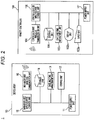
- Fig. 2 is a block diagram for explaining the portable medical device of the first embodiment.
- Fig. 2 details of a configuration of the portable medical device 1 will be described in the order of the device body 10 and the remote controller 100.
- a device body 10 functions for performing administration of a drug solution (here, insulin as an example) are intensively arranged.
- a drug solution here, insulin as an example
- Such a device body 10 includes a power supply unit 11, a driving unit 12, a date and time management unit 13, a storage unit 14, a main-body-side wireless communication unit 15, and a main-body-side input/output control unit 16 that controls these.
- the device body 10 is configured to have no user interface for operation of the driving unit 12 or the main-body-side wireless communication unit 15.
- each element constituting the device body 10 is described.
- the power supply unit 11 is for supplying electric power to each component constituting the device body 10, and is configured by, for example, a battery and a battery box to accommodate the battery.
- This device body 10 is configured such that power is turned on by, for example, mounting the battery to the battery box.
- the driving unit 12 is for performing a drug solution administration to a patient wearing the device body 10, and configured by a syringe to contain a drug solution to be administered, a pusher to be slid in the syringe, a motor and a gear mechanism for movement of the pusher, and the like.
- This driving unit 12 is configured to drive the motor by electric power from the power supply unit 11.
- the date and time management unit 13 is a program part to perform date and time management, which may be installed in a general microcomputer, and outputs date and time information.
- the storage unit 14 is a part to store various data.
- Data stored in the storage unit 14 is, for example, an administration condition of a drug solution transmitted from the remote controller 100 side, a wireless output stop setting, an administration history of a drug solution administration performed by the device body 10, and the like.
- the main-body-side wireless communication unit 15 is a part that performs wireless communication between with the remote controller 100.
- This main-body-side wireless communication unit 15 is a part that has a transmitter and a receiver and performs wireless communication using radio waves of a predetermined wavelength band, and in particular, performs wireless communication using ultra high frequency waves or microwaves.
- short-distance wireless communication with a communication distance of 100 m or less is to be performed.
- a standardized wireless communication technology such as ZigBee (registered trademark IEEE 802.15.4: frequency 868 MHz band, 915 MHz band, 2.4 GHz band), Bluetooth (registered trademark: IEEE 802.15.1: frequency 2.4 GHz band), or wireless LAN (IEEE 802.11a/b/g/n/ac: frequency 2.4 GHz band, 5 GHz band) is applied.
- ZigBee registered trademark IEEE 802.15.4: frequency 868 MHz band, 915 MHz band, 2.4 GHz band
- Bluetooth registered trademark: IEEE 802.15.1: frequency 2.4 GHz band
- wireless LAN IEEE 802.11a/b/g/n/ac: frequency 2.4 GHz band, 5 GHz band
- the main-body-side wireless communication unit 15 is configured to periodically transmit identification information for causing the remote controller 100 to recognize the device body 10.
- the device body 10 is configured to have no user interface for operation of the main-body-side wireless communication unit 15. Therefore, output of identification information by such a main-body-side wireless communication unit 15 is to be started with turning on of the power supply unit 11 as a trigger.
- Such a main-body-side wireless communication unit 15 performs transmission and reception of signals between with the controller-side wireless communication unit 105 of the remote controller 100 that has received the identification information, and the main-body-side wireless communication unit 15 establishes connection for wireless communication between with the controller-side wireless communication unit 105.
- the main-body-side wireless communication unit 15 performs transmission and reception of an administration condition of a drug solution, a wireless output stop setting, an administration history of drug solution administration, and the like, between with the remote controller 100 with which the wireless communication connection has been established.
- Such a main-body-side wireless communication unit 15 may be any one that performs wireless communication connection in the above-described procedure in particular, and for example, wireless communication using Bluetooth Low Energy (registered trademark) is performed.
- Bluetooth Low Energy registered trademark
- the device body 10 provided with such a main-body-side wireless communication unit 15 is configured as, with the remote controller 100 as a sensor device, a beacon device that transmits identification information of the device body 10 to the sensor device.
- the main-body-side input/output control unit 16 is connected to the power supply unit 11, the driving unit 12, the date and time management unit 13, the storage unit 14, and the main-body-side wireless communication unit 15.
- This main-body-side input/output control unit 16 controls input and output of signals between these units, and controls drug solution administration by driving of the driving unit 12 and wireless communication by the main-body-side wireless communication unit 15, in accordance with information received by the main-body-side wireless communication unit 15.
- Such a main-body-side input/output control unit 16 includes, for example, a central processing unit (CPU), a random access memory (RAM), and a read only memory (ROM), which are not shown here.
- the read only memory (ROM) may be the storage unit 14.
- the remote controller 100 operates the device body 10.
- this portable medical device 1 is an insulin pump
- the remote controller 100 is used for setting basal dose of insulin by the device body 10, or optionally performing bolus dose of insulin by the device body 10 in accordance with an operation by the user.
- Such a remote controller 100 includes a power supply unit 101, an input unit 102a, a display unit 102b, a date and time management unit 103, a storage unit 104, a controller-side wireless communication unit 105, and a controller-side input/output control unit 106 that controls these. Details of each component are as follows.
- the power supply unit 101 is for supplying electric power to each component constituting the remote controller 100, and is configured by, for example, a battery and a battery box to accommodate the battery, as well as a switch that turns on and off the supply of electric power from the battery, and the like.
- the input unit 102a is a user interface part to which the user inputs an on/off operation for power supply, an administration condition of a drug solution by the device body 10, a stop setting of wireless output from the main-body-side wireless communication unit 15, and selection of display contents on the display unit 102b.
- Such an input unit 102a may be, for example, a keypad or a touch panel provided on a front surface of the display unit 102b.
- the display unit 102b displays selection buttons, a ten key, and the like, for the touch panel.
- the wireless output stop setting for the main-body-side wireless communication unit 15 inputted from the input unit 102a is a stop request of wireless output, and a stop duration (for example, three hours) of the output from stopping to restarting of the wireless output or date and time (time of day) for restarting the wireless output.
- the wireless output stop setting inputted from the input unit 102a may be a time for stopping the wireless output, and a time period (for example, three hours) from stopping to restarting the wireless output or a time for restarting the wireless output.
- the time for stopping the wireless output is to be the stop request of the wireless output.
- the display unit 102b displays various setting contents, input contents from the input unit 102a, a history of drug solution administration performed by the device body 10, and the like.
- a display unit 102b is configured with use of, for example, a liquid crystal display.
- the date and time management unit 103 may be similar to the date and time management unit 13 of the device body 10, and is a program part to perform date and time management.
- the storage unit 104 is a part to store various data.
- Data stored in the storage unit 104 is, for example, a history of drug solution administration transmitted from the device body 10 side, an administration condition of a drug solution inputted in the input unit 102a, a wireless output stop setting in the main-body-side wireless communication unit 15, and further, authentication data for communication connection with the device body 10, and the like.
- the authentication data of communication connection may be identification information for recognizing the device body 10 in communication connection with this remote controller 100, and is also a link key created automatically by the communication connection.
- the controller-side wireless communication unit 105 is a part that performs wireless communication between with the device body 10.
- This controller-side wireless communication unit 105 is configured by a transmission unit and a reception unit.
- This controller-side wireless communication unit 105 is applied with a standardized wireless communication technology similar to that of the main-body-side wireless communication unit 15.
- Such a controller-side wireless communication unit 105 performs transmission and reception of signals between with the main-body-side wireless communication unit 15 of the device body 10 in communication connection, in accordance with an instruction from the controller-side input/output control unit 106, and the controller-side wireless communication unit 105 establishes connection of wireless communication between with the main-body-side wireless communication unit 15. Further, in accordance with an instruction from the controller-side input/output control unit 106, the controller-side wireless communication unit 105 transmits various settings inputted in the input unit 102a, to the main-body-side wireless communication unit 15 of the device body 10 in communication connection. Such a controller-side wireless communication unit 105 transmits a wireless output stop setting for the main-body-side wireless communication unit 15 inputted from the input unit 102a.
- the controller-side input/output control unit 106 is connected to the power supply unit 101, the input unit 102a, the display unit 102b, the date and time management unit 103, the storage unit 104, and the controller-side wireless communication unit 105. By controlling input and output of signals between these units, the controller-side input/output control unit 106 controls display on the display unit 102b and wireless communication by the controller-side wireless communication unit 105.
- the controller-side input/output control unit 106 as described above includes, for example, a central processing unit (CPU), a random access memory (RAM), and a read only memory (ROM), which are not shown here.
- the read only memory (ROM) may be the storage unit 104.
- An algorithm for the control of wireless communication by the controller-side wireless communication unit 105 executed by such a controller-side input/output control unit 106 will be described in detail in the control method of the portable medical device 1 next.
- Fig. 3 is a flowchart (part 1) for explaining the control method of the portable medical device 1 of the first embodiment, and shows a procedure (steps S11 to S20) performed by the main-body-side input/output control unit 16 of the device body 10.
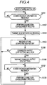
- Fig. 4 is a flowchart (part 2) for explaining the control method of the portable medical device 1 of the first embodiment, and shows a procedure (steps S101 to S108) performed by the controller-side input/output control unit 106 of the remote controller 100.
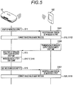
- Fig. 5 is a time chart for explaining a state of wireless communication of the portable medical device 1 of the first embodiment.
- the control method of the portable medical device 1 of the first embodiment described using these figures is a series of procedures in a case of assuming that wireless communication between the device body 10 and the remote controller 100 is temporarily stopped during drug solution administration by the device body 10.
- the procedure described below is realized by a CPU constituting the main-body-side input/output control unit 16 of the device body 10 and a CPU constituting the controller-side input/output control unit 106 of the remote controller 100 executing a program recorded in each ROM and RAM.
- step S11 when the power supply unit 11 is turned on by setting the battery in the battery box of the power supply unit 11, with this as a trigger, the main-body-side input/output control unit 16 starts wireless output from the main-body-side wireless communication unit 15.
- the main-body-side wireless communication unit 15 continuously transmits, as wireless output, identification information for identifying the device body 10 at a constant cycle of, for example, 0.5 seconds.
- step S101 when the power supply unit 101 is turned on, for example, by an operation on the input unit 102a, with this as a trigger, the controller-side input/output control unit 106 starts signal reception by the controller-side wireless communication unit 105, and determines whether or not identification information from the main-body-side wireless communication unit 15 has been received.
- the controller-side input/output control unit 106 analyzes the wireless output received by the controller-side wireless communication unit 105. Then, it is determined whether or not the received wireless output is identification information of the device body 10 in communication connection with this remote controller 100. Then, the determination is repeated until it is determined that this identification information has been received (YES), and the process proceeds to the next step S102 when it is determined that the identification information has been received (YES).
- step S102 the controller-side input/output control unit 106 performs a connection establishment process for establishing connection of wireless communication between the controller-side wireless communication unit 105 and the main-body-side wireless communication unit 15.
- step S12 the main-body-side input/output control unit 16 performs a connection establishment process for establishing connection of wireless communication between the controller-side wireless communication unit 105 and the main-body-side wireless communication unit 15.
- step S103 the controller-side input/output control unit 106 causes the controller-side wireless communication unit 105 to transmit an administration condition of a drug solution by the driving unit 12 of the device body 10.
- This administration condition is information inputted by the user from the input unit 102a or information inputted by the user from the input unit 102a and stored in the storage unit 104.
- step S13 the main-body-side input/output control unit 16 stores the administration condition of the drug solution transmitted from the controller-side wireless communication unit 105 and received by the main-body-side wireless communication unit 15, in the storage unit 14 as a set value.
- step S14 the main-body-side input/output control unit 16 controls the driving unit 12 in accordance with the administration condition stored in the storage unit 14, to start drug solution administration. Further, when performing drug solution administration, the main-body-side input/output control unit 16 stores an administration history of the drug solution actually administered by the control of the driving unit 12, in the storage unit 14. Furthermore, the main-body-side input/output control unit 16 causes the main-body-side wireless communication unit 15 to regularly transmit the administration history of the drug solution stored in the storage unit 14, to the controller-side wireless communication unit 105.
- step S104 when the administration history transmitted from the main-body-side wireless communication unit 15 has been received by the controller-side wireless communication unit 105, the controller-side input/output control unit 106 stores the received administration history in the storage unit 104, and causes the display unit 102b to display as necessary.
- step S14 performed by the device body 10 and step S104 performed by the remote controller 100 are continuously performed in accordance with the setting of the administration condition of the drug solution, stored in the storage unit 14 of the device body 10.
- a procedure described below is to be a procedure unique to the first embodiment.
- the procedure described below is a procedure in a case where it becomes necessary to stop wireless communication between the device body 10 and the remote controller 100 during execution of the normal drug solution administration, for example, such as a case where the user of the portable medical device 1 boards an aircraft in which in-flight wireless communication is prohibited, and the procedure is performed as follows.
- step S105 the controller-side input/output control unit 106 determines whether or not a wireless output stop setting has been inputted from the input unit 102a. Then, when it is determined that there is an input (YES), the process proceeds to the next step S106. Whereas, when it is determined that there is no input (NO), the process returns to step S104.
- the determination as to whether or not a wireless output stop setting by the controller-side input/output control unit 106 has been inputted may be determination based on whether or not it is time for stopping the wireless output on the basis of setting information for stopping wireless output stored in advance in the storage unit 104.
- step S106 the controller-side input/output control unit 106 causes the controller-side wireless communication unit 105 to transmit a wireless output stop setting.
- the wireless output stop setting to be transmitted here is a stop request of wireless output and a length of a time period (for example, three hours) from stopping to restarting of the wireless output, or a time for starting the wireless output.
- step S15 the main-body-side input/output control unit 16 determines whether or not a wireless output stop setting has been received in the main-body-side wireless communication unit 15 and repeats the determination until it is determined as being received (YES), and the process proceeds to the next step S16 when it is determined as being received (YES).
- step S16 the main-body-side input/output control unit 16 stops the wireless output of the main-body-side wireless communication unit 15. This interrupts the wireless connection between the main-body-side wireless communication unit 15 and the controller-side wireless communication unit 105 established in step S12 and step S102. In this state, in order to restart the wireless connection between the main-body-side wireless communication unit 15 and the controller-side wireless communication unit 105, it is necessary to perform the connection establishment process again.
- step S17 the main-body-side input/output control unit 16 stores, among the wireless output stop setting received in step S15, the length of the time period (for example, three hours) from stopping to restarting of the wireless output or the time for restarting the wireless output, in the storage unit 14.
- the length of the time period for example, three hours
- step S18 the main-body-side input/output control unit 16 determines whether or not a stop duration or a restart time after stopping of the wireless output of the main-body-side wireless communication unit 15 has reached a set time period (or time of day) stored in the storage unit 14.
- a stop duration or a restart time after stopping of the wireless output of the main-body-side wireless communication unit 15 has reached a set time period (or time of day) stored in the storage unit 14.
- the time managed by the date and time management unit 13 corresponds to the length of the time period for stopping the wireless output stored in the storage unit 14 after stopping the wireless communication, or whether or not the time for restarting the wireless output has been reached.
- step S19 the main-body-side input/output control unit 16 restarts the wireless output from the main-body-side wireless communication unit 15.
- the main-body-side wireless communication unit 15 continuously transmits, as wireless output, identification information for identifying the device body 10 at a constant cycle of, for example, 0.5 seconds.
- step S107 the controller-side input/output control unit 106 determines whether or not the controller-side wireless communication unit 105 has received identification information.
- the controller-side input/output control unit 106 analyzes the wireless output. Then, it is determined whether or not the received wireless output is identification information of the device body 10 in communication connection with this remote controller 100. Then, the determination is repeated until it is determined that this identification information has been received (YES), and the process proceeds to the next step S108 when it is determined that the identification information has been received (YES).
- step S108 the controller-side input/output control unit 106 performs a connection establishment process for establishing connection of wireless communication between the controller-side wireless communication unit 105 and the main-body-side wireless communication unit 15, and thereafter, the process returns to step S104.
- step S20 the main-body-side input/output control unit 16 performs a connection establishment process for establishing connection of wireless communication between the controller-side wireless communication unit 105 and the main-body-side wireless communication unit 15, and thereafter, the process returns to step S15.
- wireless output can be automatically restarted after the lapse of a wireless stop duration or a restart time even when the wireless output of the device body 10 having no user interface is stopped by an operation of the remote controller 100. Therefore, it becomes possible again to change the setting of drug solution administration, and to perform additional drug solution administration, that is, bolus administration of insulin from the device body 10.
- Fig. 6 is a schematic configuration view of a portable medical device 2 of a second embodiment.
- the portable medical device 2 of the second embodiment shown in Fig. 6 is different from the portable medical device 1 of the first embodiment described above in that a device body 10' includes an attachment detection unit 21 and a blockage detection unit 22 as a drive state detection unit. Further, a procedure of control performed by a main-body-side input/output control unit 16' and a controller-side input/output control unit 106' described later is different.
- Other configurations are similar to those in the first embodiment. Therefore, in the following, components similar to those in the first embodiment are denoted by the same reference numerals, and only configurations different from the first embodiment will be described while redundant description will be omitted.
- Fig. 7 is a block diagram for explaining the portable medical device of the second embodiment.
- Fig. 7 features of a configuration of the device body 10' of the portable medical device 2 will be described.
- a device body 10' functions for performing administration of a drug solution (here, insulin as an example) are intensively arranged.
- a drug solution here, insulin as an example
- Such a device body 10' includes a power supply unit 11, a driving unit 12, a date and time management unit 13, a storage unit 14, and a main-body-side wireless communication unit 15 similar to those of the first embodiment, and further includes the attachment detection unit 21 and the blockage detection unit 22. Further, the device body 10' includes the main-body-side input/output control unit 16' that controls these.
- the attachment detection unit 21, the blockage detection unit 22, and the main-body-side input/output control unit 16' having a configuration different from that of the first embodiment are as follows.
- the attachment detection unit 21 is for detecting whether or not the device body 10' is attached to a cradle 200.
- an attachment detection unit 21 for example, one is exemplified that is configured by a light emitting element and a light receiving element that detects reflected light of light emitted from the light emitting element.
- Such an attachment detection unit 21 has a configuration in which, in a state where the device body 10' is attached to the cradle 200, light emitted from the light emitting element is reflected by the cradle 200 and detected by the light receiving element, and whereby it is detected that the device body 10' is attached to the cradle 200.
- the attachment detection unit 21 also serves as input means in the device body 10'. That is, the attachment detection unit 21 switches on and off of a detection state of reflected light in the light receiving element by switching of attachment/non-attachment of the device body 10' to the cradle 200, that is, by attachment and removal of the device body 10' to and from the cradle 200. Therefore, for example, with a speed of this on/off switching, predetermined processing related to control of the main-body-side wireless communication unit 15 is associated. This association is stored in the storage unit 14.
- one switching operation of removing the device body 10' in a state of being attached to the cradle 200 to set in an non-attached state and attaching again within a predetermined time period (10 seconds) is associated with processing of extending a stop duration or a restart time of the wireless output of the main-body-side wireless communication unit 15, by a predetermined extension time (for example, 10 minutes).
- two switching operations within a predetermined time period (10 seconds) are associated with a trigger for forcibly restarting the wireless output of the main-body-side wireless communication unit 15.
- the attachment detection unit 21 is not limited to the one configured by the light emitting element and the light receiving element as described above, and may be, for example, one that detects an attachment state of the device body 10' to the cradle 200 by mechanical switching, a reed switch, or the like.
- the blockage detection unit 22 is a drive state detection unit for detection of a drive failure of the driving unit 12.
- this blockage detection unit 22 may be an encoder provided in the gear mechanism, as an example.
- the blockage detection unit 22 may detect a drive state by a pressure sensor or a flow rate sensor.
- the main-body-side input/output control unit 16' is connected to the power supply unit 11, the driving unit 12, the date and time management unit 13, the storage unit 14, the main-body-side wireless communication unit 15, the attachment detection unit 21, and the blockage detection unit 22.
- This main-body-side input/output control unit 16' controls input and output of signals between these units, and controls drug solution administration by driving of the driving unit 12 and wireless communication by the main-body-side wireless communication unit 15, in accordance with information received by the main-body-side wireless communication unit 15 and signals from the attachment detection unit 21 and the blockage detection unit 22.
- main-body-side input/output control unit 16' includes, for example, a central processing unit (CPU), a random access memory (RAM), and a read only memory (ROM), which are not shown here, is similar to the first embodiment.
- CPU central processing unit
- RAM random access memory
- ROM read only memory
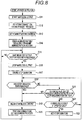
- Fig. 8 is a flowchart for explaining the control method of the portable medical device 2 of the second embodiment, and shows a procedure to be performed by the main-body-side input/output control unit 16' of the device body 10'.
- a difference between the procedure shown in Fig. 8 and the procedure to be performed by the main-body-side input/output control unit 16 of the device body 10 of the first embodiment described using Fig. 3 is that steps S21 to S23 are added after the determination in step S18'.
- Other steps S11 to S20 are similar to the procedure described in the first embodiment.
- a procedure to be performed by the controller-side input/output control unit 106 of the remote controller 100 is similar to steps S101 to S108 described using Fig. 4 .
- Fig. 7 a procedure different from that of the first embodiment will be described with reference to Fig. 8 .
- step S18' the main-body-side input/output control unit 16' determines whether or not a stop duration or a restart time after stopping of the wireless output of the main-body-side wireless communication unit 15 has reached a stop duration or a restart time stored in the storage unit 14. This determination is performed similarly to step S18 in the first embodiment, and the process proceeds to the next step S19 similarly to the first embodiment when it is determined as having reached (YES).
- step S21 the main-body-side input/output control unit 16' makes two determinations as to whether or not forced restart of wireless output has been detected, and whether or not an error contrary to a setting condition has occurred in drug solution administration from the driving unit 12.
- the error includes blockage of a drug solution administration route, lack of a remaining drug solution, and the like.
- the main-body-side input/output control unit 16' determines whether or not there is detection associated with forced restart of the wireless output, in the attachment detection unit 21.
- it is determined whether or not an operation for removing the device body 10' in a state of being attached to the cradle 200 from the cradle 200 and attaching again has been detected twice within a predetermined time period (10 seconds) in the attachment detection unit 21.
- main-body-side input/output control unit 16' determines whether or not an occurrence of blockage in an administration route of the drug solution from the driving unit 12 has been detected in the blockage detection unit 22.
- step S19 the wireless output from the main-body-side wireless communication unit 15 is restarted, and identification information for identifying the device body 10' is continuously transmitted at a constant cycle of, for example, 0.5 seconds. Further, in the next step S20, a connection establishment process of wireless communication between the main-body-side wireless communication unit 15 and the controller-side wireless communication unit 105 is performed.
- blockage detection unit 22 when the blockage detection unit 22 has detected that blockage has occurred in an administration route of the drug solution from the driving unit 12, blockage occurrence information is transmitted from the main-body-side wireless communication unit 15 to the remote controller 100 in accordance with a normal procedure.
- a notification unit may be provided in the device body 10', and notification may be made by an alarm sound or vibration. This has the effect that the user can quickly recognize the abnormality. Also in this case, even without using the remote controller 100, it becomes possible to input a postponement or stop of communication restart of the device body 10' by an operation of the attachment detection unit 21.
- step S21 determines that none is detected in step S21 (NO)
- the process proceeds to step S22.
- step S22 the main-body-side input/output control unit 16' determines whether or not extension of wireless output has been detected.
- the main-body-side input/output control unit 16' determines whether or not there is detection associated with extension of wireless output, in the attachment detection unit 21.
- it is determined whether or not an operation for removing the device body 10' in a state of being attached to the cradle 200 from the cradle 200 and attaching again has been detected once within a predetermined time period (10 seconds) in the attachment detection unit 21.
- step S23 When it is determined as being detected (YES), the process proceeds to step S23. Whereas, when it is determined as not being detected (NO), the process returns to step S18'.
- step S23 the main-body-side input/output control unit 16' performs a process of adding a stop duration of the wireless output (or a time for restarting the wireless output) stored in the storage unit 14.
- the stop duration of the wireless output (or the time for restarting the wireless output) stored in the storage unit 14 is rewritten to a time extended by a predetermined extension time (for example, 10 minutes). Thereafter, the process returns to step S18' to continue processing.
- the wireless output of the device body 10 in a state where the wireless output of the device body 10 having no user interface is stopped, it is possible forcibly restart the wireless output of the device body 10' and extend the stop of the wireless output, even without operation of the remote controller. Therefore, for example, when the user of the portable medical device 2 is on board an aircraft in which in-flight wireless communication is prohibited, the stop of the wireless output can be extended if arrival of the aircraft is delayed. In addition, even when an unexpected situation related to drug solution administration occurs while the wireless output is stopped, the wireless output of the device body 10 can be restarted urgently to enable the remote controller 100 to operate the device body 10.
Landscapes
- Engineering & Computer Science (AREA)
- Health & Medical Sciences (AREA)
- Computer Networks & Wireless Communication (AREA)
- Biomedical Technology (AREA)
- General Health & Medical Sciences (AREA)
- Signal Processing (AREA)
- Public Health (AREA)
- Primary Health Care (AREA)
- Medical Informatics (AREA)
- Epidemiology (AREA)
- Vascular Medicine (AREA)
- General Business, Economics & Management (AREA)
- Animal Behavior & Ethology (AREA)
- Hematology (AREA)
- Heart & Thoracic Surgery (AREA)
- Veterinary Medicine (AREA)
- Business, Economics & Management (AREA)
- Life Sciences & Earth Sciences (AREA)
- Anesthesiology (AREA)
- General Physics & Mathematics (AREA)
- Physics & Mathematics (AREA)
- Infusion, Injection, And Reservoir Apparatuses (AREA)
- Selective Calling Equipment (AREA)
- Chemical & Material Sciences (AREA)
- Bioinformatics & Cheminformatics (AREA)
- Medicinal Chemistry (AREA)
Abstract
Description
- The present invention relates to a portable medical device and a control method of the portable medical device.
- As a treatment for diabetic patients, a treatment of continuously infusing a small amount of insulin into the patient's body is performed. In this treatment, in order to continuously administer a drug solution (insulin) to a patient, there is used a portable drug solution administration device (so-called insulin pump) provided with a device body that is fixed to the patient's body or clothes to be used, and a remote controller to control the device body through wireless communication.
- In order to suppress battery consumption on the device body side and reduce its battery capacity, such a portable medical device using wireless communication has a configuration in which wireless communication is started, with a transmission signal from the device body as a trigger, by the remote controller receiving the transmission signal, at the time of wireless communication. Furthermore, the wireless communication between the device body and the remote controller can be interrupted (see
Patent Literature 1 below), by setting a communication setting between the device body and the remote controller to an in-flight mode when the user boards an airplane. - Patent Literature 1:
US 2016/0,038,671 A - However, in a case where no user interface is provided on the device body, the portable medical device configured as described above cannot restart the wireless communication without an operation of the remote controller, after the wireless communication between the device body and the remote controller is once interrupted. Therefore, although drug solution administration by the device body is continued, it becomes impossible to perform control such as setting change of administration and additional drug solution administration.
- Accordingly, an object of the present invention is to provide a portable medical device and a control method of the portable medical device capable of restarting wireless communication even without an operation of a remote controller, even when wireless communication between a device body having no user interface and the remote controller to control the device body is stopped. Solution to Problem
- The present invention for achieving such an object is a portable medical device including a device body and a remote controller that operates driving of the device body. The device body includes: a power supply unit; a driving unit driven by electric power from the power supply unit; a main-body-side wireless communication unit that outputs identification information at a predetermined cycle when the power supply unit is turned on; and a main-body-side input/output control unit that controls driving of the driving unit and output of the main-body-side wireless communication unit, in accordance with information received by the main-body-side wireless communication unit. The remote controller includes: an input unit that is inputted with, together with a stop request of output for the main-body-side wireless communication unit, a stop duration of the output or a restart time of the output; and a controller-side wireless communication unit that establishes wireless connection between with the main-body-side wireless communication unit that has outputted the identification information by receiving the identification information outputted from the main-body-side wireless communication unit, and outputs, to the main-body-side wireless communication unit, information that is related to stop of the output and inputted from the input unit. Advantageous Effects of Invention
- According to the present invention having the configuration above, it becomes possible to restart wireless communication without an operation of the remote controller, even when wireless communication between the device body having no user interface and the remote controller to control the device body is stopped. Brief Description of Drawings
-
-
Fig. 1 is a schematic configuration view of a portable medical device of a first embodiment. -
Fig. 2 is a block diagram for explaining the portable medical device of the first embodiment. -
Fig. 3 is a flowchart (part 1) for explaining a control method of the portable medical device of the first embodiment. -
Fig. 4 is a flowchart (part 2) for explaining the control method of the portable medical device of the first embodiment. -
Fig. 5 is a time chart for explaining a state of wireless communication of the portable medical device of the first embodiment. -
Fig. 6 is a schematic configuration view of a portable medical device of a second embodiment. -
Fig. 7 is a block diagram for explaining the portable medical device of the second embodiment. -
Fig. 8 is a flowchart for explaining a control method of the portable medical device of the second embodiment. Description of Embodiments - Hereinafter, each embodiment applied with the present invention will be described in detail with reference to the drawings. Note that, in each embodiment, a description is given to a configuration in a case where the present invention is applied to a drug solution administration device such as an insulin pump, as a portable medical device. However, the portable medical device of the present invention can be widely applied to portable medical devices configured by a device body and a remote controller to operate or monitor this device body through wireless communication, for example, such as a pain relief device or a biological information measurement device. Further, without limiting to the device body having no user interface as in the embodiment, even a device body having a user interface can restart wireless communication without performing an input operation.
-
Fig. 1 is a schematic configuration view of a portable medical device of a first embodiment. A portablemedical device 1 of the first embodiment shown inFig. 1 is configured by adevice body 10 and aremote controller 100 to operate thedevice body 10 through wireless communication. - Among them, the
device body 10 is a pump unit to administrate a drug solution (insulin, as an example) to a patient for a long time, and is used by being worn on the skin of the patient via acradle 200 that is to be bonded to the skin. Note that thecradle 200 includes acatheter port 201, and is used by being bonded to the skin of the patient. Whereas, theremote controller 100 is carried and used without being worn on the skin of the patient. Such aremote controller 100 is configured as a central device (master device) for operation of thedevice body 10 through wireless communication, when thedevice body 10 is a peripheral device (slave device). -
Fig. 2 is a block diagram for explaining the portable medical device of the first embodiment. Hereinafter, with reference toFig. 2 , details of a configuration of the portablemedical device 1 will be described in the order of thedevice body 10 and theremote controller 100. - In the
device body 10, functions for performing administration of a drug solution (here, insulin as an example) are intensively arranged. Such adevice body 10 includes apower supply unit 11, adriving unit 12, a date andtime management unit 13, astorage unit 14, a main-body-sidewireless communication unit 15, and a main-body-side input/output control unit 16 that controls these. However, thedevice body 10 is configured to have no user interface for operation of thedriving unit 12 or the main-body-sidewireless communication unit 15. Hereinafter, each element constituting thedevice body 10 is described. - The
power supply unit 11 is for supplying electric power to each component constituting thedevice body 10, and is configured by, for example, a battery and a battery box to accommodate the battery. Thisdevice body 10 is configured such that power is turned on by, for example, mounting the battery to the battery box. - The driving
unit 12 is for performing a drug solution administration to a patient wearing thedevice body 10, and configured by a syringe to contain a drug solution to be administered, a pusher to be slid in the syringe, a motor and a gear mechanism for movement of the pusher, and the like. Thisdriving unit 12 is configured to drive the motor by electric power from thepower supply unit 11. - The date and
time management unit 13 is a program part to perform date and time management, which may be installed in a general microcomputer, and outputs date and time information. - The
storage unit 14 is a part to store various data. Data stored in thestorage unit 14 is, for example, an administration condition of a drug solution transmitted from theremote controller 100 side, a wireless output stop setting, an administration history of a drug solution administration performed by thedevice body 10, and the like. - The main-body-side
wireless communication unit 15 is a part that performs wireless communication between with theremote controller 100. This main-body-sidewireless communication unit 15 is a part that has a transmitter and a receiver and performs wireless communication using radio waves of a predetermined wavelength band, and in particular, performs wireless communication using ultra high frequency waves or microwaves. Here, in the main-body-sidewireless communication unit 15, short-distance wireless communication with a communication distance of 100 m or less is to be performed. Specifically, a standardized wireless communication technology such as ZigBee (registered trademark IEEE 802.15.4: frequency 868 MHz band, 915 MHz band, 2.4 GHz band), Bluetooth (registered trademark: IEEE 802.15.1: frequency 2.4 GHz band), or wireless LAN (IEEE 802.11a/b/g/n/ac: frequency 2.4 GHz band, 5 GHz band) is applied. - In particular, the main-body-side
wireless communication unit 15 is configured to periodically transmit identification information for causing theremote controller 100 to recognize thedevice body 10. Here, thedevice body 10 is configured to have no user interface for operation of the main-body-sidewireless communication unit 15. Therefore, output of identification information by such a main-body-sidewireless communication unit 15 is to be started with turning on of thepower supply unit 11 as a trigger. - Further, such a main-body-side
wireless communication unit 15 performs transmission and reception of signals between with the controller-sidewireless communication unit 105 of theremote controller 100 that has received the identification information, and the main-body-sidewireless communication unit 15 establishes connection for wireless communication between with the controller-sidewireless communication unit 105. - Furthermore, in accordance with an instruction from the main-body-side input/
output control unit 16, the main-body-sidewireless communication unit 15 performs transmission and reception of an administration condition of a drug solution, a wireless output stop setting, an administration history of drug solution administration, and the like, between with theremote controller 100 with which the wireless communication connection has been established. - Such a main-body-side
wireless communication unit 15 may be any one that performs wireless communication connection in the above-described procedure in particular, and for example, wireless communication using Bluetooth Low Energy (registered trademark) is performed. - Further, the
device body 10 provided with such a main-body-sidewireless communication unit 15 is configured as, with theremote controller 100 as a sensor device, a beacon device that transmits identification information of thedevice body 10 to the sensor device. - The main-body-side input/
output control unit 16 is connected to thepower supply unit 11, the drivingunit 12, the date andtime management unit 13, thestorage unit 14, and the main-body-sidewireless communication unit 15. This main-body-side input/output control unit 16 controls input and output of signals between these units, and controls drug solution administration by driving of the drivingunit 12 and wireless communication by the main-body-sidewireless communication unit 15, in accordance with information received by the main-body-sidewireless communication unit 15. - Such a main-body-side input/
output control unit 16 includes, for example, a central processing unit (CPU), a random access memory (RAM), and a read only memory (ROM), which are not shown here. The read only memory (ROM) may be thestorage unit 14. An algorithm executed by such a main-body-side input/output control unit 16 for the control of drug solution administration from the drivingunit 12 and wireless communication by the main-body-sidewireless communication unit 15 will be described in detail in a control method of the portablemedical device 1 below. - The
remote controller 100 operates thedevice body 10. In a case where this portablemedical device 1 is an insulin pump, theremote controller 100 is used for setting basal dose of insulin by thedevice body 10, or optionally performing bolus dose of insulin by thedevice body 10 in accordance with an operation by the user. - Such a
remote controller 100 includes apower supply unit 101, aninput unit 102a, adisplay unit 102b, a date andtime management unit 103, astorage unit 104, a controller-sidewireless communication unit 105, and a controller-side input/output control unit 106 that controls these. Details of each component are as follows. - The
power supply unit 101 is for supplying electric power to each component constituting theremote controller 100, and is configured by, for example, a battery and a battery box to accommodate the battery, as well as a switch that turns on and off the supply of electric power from the battery, and the like. - The
input unit 102a is a user interface part to which the user inputs an on/off operation for power supply, an administration condition of a drug solution by thedevice body 10, a stop setting of wireless output from the main-body-sidewireless communication unit 15, and selection of display contents on thedisplay unit 102b. Such aninput unit 102a may be, for example, a keypad or a touch panel provided on a front surface of thedisplay unit 102b. In a case where theinput unit 102a is a touch panel, thedisplay unit 102b displays selection buttons, a ten key, and the like, for the touch panel. - Here, the wireless output stop setting for the main-body-side
wireless communication unit 15 inputted from theinput unit 102a is a stop request of wireless output, and a stop duration (for example, three hours) of the output from stopping to restarting of the wireless output or date and time (time of day) for restarting the wireless output. In addition, the wireless output stop setting inputted from theinput unit 102a may be a time for stopping the wireless output, and a time period (for example, three hours) from stopping to restarting the wireless output or a time for restarting the wireless output. In this case, the time for stopping the wireless output is to be the stop request of the wireless output. - The
display unit 102b displays various setting contents, input contents from theinput unit 102a, a history of drug solution administration performed by thedevice body 10, and the like. Such adisplay unit 102b is configured with use of, for example, a liquid crystal display. - The date and
time management unit 103 may be similar to the date andtime management unit 13 of thedevice body 10, and is a program part to perform date and time management. - The
storage unit 104 is a part to store various data. Data stored in thestorage unit 104 is, for example, a history of drug solution administration transmitted from thedevice body 10 side, an administration condition of a drug solution inputted in theinput unit 102a, a wireless output stop setting in the main-body-sidewireless communication unit 15, and further, authentication data for communication connection with thedevice body 10, and the like. Note that the authentication data of communication connection may be identification information for recognizing thedevice body 10 in communication connection with thisremote controller 100, and is also a link key created automatically by the communication connection. - The controller-side
wireless communication unit 105 is a part that performs wireless communication between with thedevice body 10. This controller-sidewireless communication unit 105 is configured by a transmission unit and a reception unit. This controller-sidewireless communication unit 105 is applied with a standardized wireless communication technology similar to that of the main-body-sidewireless communication unit 15. - Such a controller-side
wireless communication unit 105 performs transmission and reception of signals between with the main-body-sidewireless communication unit 15 of thedevice body 10 in communication connection, in accordance with an instruction from the controller-side input/output control unit 106, and the controller-sidewireless communication unit 105 establishes connection of wireless communication between with the main-body-sidewireless communication unit 15. Further, in accordance with an instruction from the controller-side input/output control unit 106, the controller-sidewireless communication unit 105 transmits various settings inputted in theinput unit 102a, to the main-body-sidewireless communication unit 15 of thedevice body 10 in communication connection. Such a controller-sidewireless communication unit 105 transmits a wireless output stop setting for the main-body-sidewireless communication unit 15 inputted from theinput unit 102a. - The controller-side input/
output control unit 106 is connected to thepower supply unit 101, theinput unit 102a, thedisplay unit 102b, the date andtime management unit 103, thestorage unit 104, and the controller-sidewireless communication unit 105. By controlling input and output of signals between these units, the controller-side input/output control unit 106 controls display on thedisplay unit 102b and wireless communication by the controller-sidewireless communication unit 105. - The controller-side input/
output control unit 106 as described above includes, for example, a central processing unit (CPU), a random access memory (RAM), and a read only memory (ROM), which are not shown here. The read only memory (ROM) may be thestorage unit 104. An algorithm for the control of wireless communication by the controller-sidewireless communication unit 105 executed by such a controller-side input/output control unit 106 will be described in detail in the control method of the portablemedical device 1 next. -
Fig. 3 is a flowchart (part 1) for explaining the control method of the portablemedical device 1 of the first embodiment, and shows a procedure (steps S11 to S20) performed by the main-body-side input/output control unit 16 of thedevice body 10. Further,Fig. 4 is a flowchart (part 2) for explaining the control method of the portablemedical device 1 of the first embodiment, and shows a procedure (steps S101 to S108) performed by the controller-side input/output control unit 106 of theremote controller 100. Furthermore,Fig. 5 is a time chart for explaining a state of wireless communication of the portablemedical device 1 of the first embodiment. - The control method of the portable
medical device 1 of the first embodiment described using these figures is a series of procedures in a case of assuming that wireless communication between thedevice body 10 and theremote controller 100 is temporarily stopped during drug solution administration by thedevice body 10. The procedure described below is realized by a CPU constituting the main-body-side input/output control unit 16 of thedevice body 10 and a CPU constituting the controller-side input/output control unit 106 of theremote controller 100 executing a program recorded in each ROM and RAM. - Hereinafter, the control method of the portable
medical device 1 will be described in the order shown in the flowcharts ofFigs. 3 and4 , with reference toFigs. 2 and5 . - First, in step S11, when the
power supply unit 11 is turned on by setting the battery in the battery box of thepower supply unit 11, with this as a trigger, the main-body-side input/output control unit 16 starts wireless output from the main-body-sidewireless communication unit 15. Here, the main-body-sidewireless communication unit 15 continuously transmits, as wireless output, identification information for identifying thedevice body 10 at a constant cycle of, for example, 0.5 seconds. - Whereas, in step S101, when the
power supply unit 101 is turned on, for example, by an operation on theinput unit 102a, with this as a trigger, the controller-side input/output control unit 106 starts signal reception by the controller-sidewireless communication unit 105, and determines whether or not identification information from the main-body-sidewireless communication unit 15 has been received. Here, the controller-side input/output control unit 106 analyzes the wireless output received by the controller-sidewireless communication unit 105. Then, it is determined whether or not the received wireless output is identification information of thedevice body 10 in communication connection with thisremote controller 100. Then, the determination is repeated until it is determined that this identification information has been received (YES), and the process proceeds to the next step S102 when it is determined that the identification information has been received (YES). - Next, in step S102, the controller-side input/
output control unit 106 performs a connection establishment process for establishing connection of wireless communication between the controller-sidewireless communication unit 105 and the main-body-sidewireless communication unit 15. - Similarly, in step S12, the main-body-side input/
output control unit 16 performs a connection establishment process for establishing connection of wireless communication between the controller-sidewireless communication unit 105 and the main-body-sidewireless communication unit 15. - Thereafter, in step S103, the controller-side input/
output control unit 106 causes the controller-sidewireless communication unit 105 to transmit an administration condition of a drug solution by the drivingunit 12 of thedevice body 10. This administration condition is information inputted by the user from theinput unit 102a or information inputted by the user from theinput unit 102a and stored in thestorage unit 104. - Whereas, in step S13, the main-body-side input/
output control unit 16 stores the administration condition of the drug solution transmitted from the controller-sidewireless communication unit 105 and received by the main-body-sidewireless communication unit 15, in thestorage unit 14 as a set value. - Thereafter, in step S14, the main-body-side input/
output control unit 16 controls the drivingunit 12 in accordance with the administration condition stored in thestorage unit 14, to start drug solution administration. Further, when performing drug solution administration, the main-body-side input/output control unit 16 stores an administration history of the drug solution actually administered by the control of the drivingunit 12, in thestorage unit 14. Furthermore, the main-body-side input/output control unit 16 causes the main-body-sidewireless communication unit 15 to regularly transmit the administration history of the drug solution stored in thestorage unit 14, to the controller-sidewireless communication unit 105. - Whereas, in step S104, when the administration history transmitted from the main-body-side
wireless communication unit 15 has been received by the controller-sidewireless communication unit 105, the controller-side input/output control unit 106 stores the received administration history in thestorage unit 104, and causes thedisplay unit 102b to display as necessary. - The above procedure is a procedure of a normal drug solution administration by the portable
medical device 1. Among these, step S14 performed by thedevice body 10 and step S104 performed by theremote controller 100 are continuously performed in accordance with the setting of the administration condition of the drug solution, stored in thestorage unit 14 of thedevice body 10. - Then, a procedure described below is to be a procedure unique to the first embodiment. The procedure described below is a procedure in a case where it becomes necessary to stop wireless communication between the
device body 10 and theremote controller 100 during execution of the normal drug solution administration, for example, such as a case where the user of the portablemedical device 1 boards an aircraft in which in-flight wireless communication is prohibited, and the procedure is performed as follows. - First, in step S105, the controller-side input/
output control unit 106 determines whether or not a wireless output stop setting has been inputted from theinput unit 102a. Then, when it is determined that there is an input (YES), the process proceeds to the next step S106. Whereas, when it is determined that there is no input (NO), the process returns to step S104. - Note that the determination as to whether or not a wireless output stop setting by the controller-side input/
output control unit 106 has been inputted may be determination based on whether or not it is time for stopping the wireless output on the basis of setting information for stopping wireless output stored in advance in thestorage unit 104. - Next, in step S106, the controller-side input/
output control unit 106 causes the controller-sidewireless communication unit 105 to transmit a wireless output stop setting. The wireless output stop setting to be transmitted here is a stop request of wireless output and a length of a time period (for example, three hours) from stopping to restarting of the wireless output, or a time for starting the wireless output. - Whereas, in step S15, the main-body-side input/
output control unit 16 determines whether or not a wireless output stop setting has been received in the main-body-sidewireless communication unit 15 and repeats the determination until it is determined as being received (YES), and the process proceeds to the next step S16 when it is determined as being received (YES). - Next, in step S16, the main-body-side input/
output control unit 16 stops the wireless output of the main-body-sidewireless communication unit 15. This interrupts the wireless connection between the main-body-sidewireless communication unit 15 and the controller-sidewireless communication unit 105 established in step S12 and step S102. In this state, in order to restart the wireless connection between the main-body-sidewireless communication unit 15 and the controller-sidewireless communication unit 105, it is necessary to perform the connection establishment process again. - Further, in step S17, the main-body-side input/
output control unit 16 stores, among the wireless output stop setting received in step S15, the length of the time period (for example, three hours) from stopping to restarting of the wireless output or the time for restarting the wireless output, in thestorage unit 14. - Further, in step S18, the main-body-side input/
output control unit 16 determines whether or not a stop duration or a restart time after stopping of the wireless output of the main-body-sidewireless communication unit 15 has reached a set time period (or time of day) stored in thestorage unit 14. Here, it is determined whether or not the time managed by the date andtime management unit 13 corresponds to the length of the time period for stopping the wireless output stored in thestorage unit 14 after stopping the wireless communication, or whether or not the time for restarting the wireless output has been reached. - Then, the determination is repeated until it is determined as being reached (YES), and the process proceeds to the next step S19 when it is determined as being reached (YES).
- Next, in step S19, the main-body-side input/
output control unit 16 restarts the wireless output from the main-body-sidewireless communication unit 15. Here, the main-body-sidewireless communication unit 15 continuously transmits, as wireless output, identification information for identifying thedevice body 10 at a constant cycle of, for example, 0.5 seconds. - Whereas, in step S107, the controller-side input/
output control unit 106 determines whether or not the controller-sidewireless communication unit 105 has received identification information. Here, when the controller-sidewireless communication unit 105 has received wireless output, the controller-side input/output control unit 106 analyzes the wireless output. Then, it is determined whether or not the received wireless output is identification information of thedevice body 10 in communication connection with thisremote controller 100. Then, the determination is repeated until it is determined that this identification information has been received (YES), and the process proceeds to the next step S108 when it is determined that the identification information has been received (YES). - Next, in step S108, the controller-side input/
output control unit 106 performs a connection establishment process for establishing connection of wireless communication between the controller-sidewireless communication unit 105 and the main-body-sidewireless communication unit 15, and thereafter, the process returns to step S104. - Similarly, in step S20, the main-body-side input/
output control unit 16 performs a connection establishment process for establishing connection of wireless communication between the controller-sidewireless communication unit 105 and the main-body-sidewireless communication unit 15, and thereafter, the process returns to step S15. - According to the first embodiment described above, for example, when the user boards an aircraft in which in-flight wireless communication is prohibited, wireless output can be automatically restarted after the lapse of a wireless stop duration or a restart time even when the wireless output of the
device body 10 having no user interface is stopped by an operation of theremote controller 100. Therefore, it becomes possible again to change the setting of drug solution administration, and to perform additional drug solution administration, that is, bolus administration of insulin from thedevice body 10. -
Fig. 6 is a schematic configuration view of a portablemedical device 2 of a second embodiment. The portablemedical device 2 of the second embodiment shown inFig. 6 is different from the portablemedical device 1 of the first embodiment described above in that a device body 10' includes anattachment detection unit 21 and ablockage detection unit 22 as a drive state detection unit. Further, a procedure of control performed by a main-body-side input/output control unit 16' and a controller-side input/output control unit 106' described later is different. Other configurations are similar to those in the first embodiment. Therefore, in the following, components similar to those in the first embodiment are denoted by the same reference numerals, and only configurations different from the first embodiment will be described while redundant description will be omitted. -
Fig. 7 is a block diagram for explaining the portable medical device of the second embodiment. Hereinafter, with reference toFig. 7 , features of a configuration of the device body 10' of the portablemedical device 2 will be described. - In the device body 10', functions for performing administration of a drug solution (here, insulin as an example) are intensively arranged. Such a device body 10' includes a
power supply unit 11, a drivingunit 12, a date andtime management unit 13, astorage unit 14, and a main-body-sidewireless communication unit 15 similar to those of the first embodiment, and further includes theattachment detection unit 21 and theblockage detection unit 22. Further, the device body 10' includes the main-body-side input/output control unit 16' that controls these. Among them, theattachment detection unit 21, theblockage detection unit 22, and the main-body-side input/output control unit 16' having a configuration different from that of the first embodiment are as follows. - The
attachment detection unit 21 is for detecting whether or not the device body 10' is attached to acradle 200. As an example of such anattachment detection unit 21, for example, one is exemplified that is configured by a light emitting element and a light receiving element that detects reflected light of light emitted from the light emitting element. Such anattachment detection unit 21 has a configuration in which, in a state where the device body 10' is attached to thecradle 200, light emitted from the light emitting element is reflected by thecradle 200 and detected by the light receiving element, and whereby it is detected that the device body 10' is attached to thecradle 200. - Further, in particular, the
attachment detection unit 21 also serves as input means in the device body 10'. That is, theattachment detection unit 21 switches on and off of a detection state of reflected light in the light receiving element by switching of attachment/non-attachment of the device body 10' to thecradle 200, that is, by attachment and removal of the device body 10' to and from thecradle 200. Therefore, for example, with a speed of this on/off switching, predetermined processing related to control of the main-body-sidewireless communication unit 15 is associated. This association is stored in thestorage unit 14. - For example, one switching operation of removing the device body 10' in a state of being attached to the
cradle 200 to set in an non-attached state and attaching again within a predetermined time period (10 seconds) is associated with processing of extending a stop duration or a restart time of the wireless output of the main-body-sidewireless communication unit 15, by a predetermined extension time (for example, 10 minutes). - Further, two switching operations within a predetermined time period (10 seconds) are associated with a trigger for forcibly restarting the wireless output of the main-body-side
wireless communication unit 15. - Note that the
attachment detection unit 21 is not limited to the one configured by the light emitting element and the light receiving element as described above, and may be, for example, one that detects an attachment state of the device body 10' to thecradle 200 by mechanical switching, a reed switch, or the like. - The
blockage detection unit 22 is a drive state detection unit for detection of a drive failure of the drivingunit 12. For example, in a case where the drivingunit 12 is configured by a syringe to contain a drug solution to be administered, a pusher to be slid in the syringe, a motor and gear mechanism for movement of the pusher, and the like, thisblockage detection unit 22 may be an encoder provided in the gear mechanism, as an example. In addition, theblockage detection unit 22 may detect a drive state by a pressure sensor or a flow rate sensor. - The main-body-side input/output control unit 16' is connected to the
power supply unit 11, the drivingunit 12, the date andtime management unit 13, thestorage unit 14, the main-body-sidewireless communication unit 15, theattachment detection unit 21, and theblockage detection unit 22. This main-body-side input/output control unit 16' controls input and output of signals between these units, and controls drug solution administration by driving of the drivingunit 12 and wireless communication by the main-body-sidewireless communication unit 15, in accordance with information received by the main-body-sidewireless communication unit 15 and signals from theattachment detection unit 21 and theblockage detection unit 22. - The fact that such a main-body-side input/output control unit 16' includes, for example, a central processing unit (CPU), a random access memory (RAM), and a read only memory (ROM), which are not shown here, is similar to the first embodiment.
- Next, an algorithm executed by such a main-body-side input/output control unit 16' for the control of drug solution administration from the driving
unit 12 and wireless communication by the main-body-sidewireless communication unit 15 will be described as a control method of the portablemedical device 2. -
Fig. 8 is a flowchart for explaining the control method of the portablemedical device 2 of the second embodiment, and shows a procedure to be performed by the main-body-side input/output control unit 16' of the device body 10'. A difference between the procedure shown inFig. 8 and the procedure to be performed by the main-body-side input/output control unit 16 of thedevice body 10 of the first embodiment described usingFig. 3 is that steps S21 to S23 are added after the determination in step S18'. Other steps S11 to S20 are similar to the procedure described in the first embodiment. Further, a procedure to be performed by the controller-side input/output control unit 106 of theremote controller 100 is similar to steps S101 to S108 described usingFig. 4 . Hereinafter, with reference toFig. 7 , a procedure different from that of the first embodiment will be described with reference toFig. 8 . - In step S18', the main-body-side input/output control unit 16' determines whether or not a stop duration or a restart time after stopping of the wireless output of the main-body-side
wireless communication unit 15 has reached a stop duration or a restart time stored in thestorage unit 14. This determination is performed similarly to step S18 in the first embodiment, and the process proceeds to the next step S19 similarly to the first embodiment when it is determined as having reached (YES). - Whereas, when the main-body-side input/output control unit 16' determines that the stop duration or the restart time after stopping of the wireless output of the main-body-side
wireless communication unit 15 has not reached the stop duration or the restart time stored in the storage unit 14 (NO), the process proceeds to step S21. - In step S21, the main-body-side input/output control unit 16' makes two determinations as to whether or not forced restart of wireless output has been detected, and whether or not an error contrary to a setting condition has occurred in drug solution administration from the driving
unit 12. The error includes blockage of a drug solution administration route, lack of a remaining drug solution, and the like. - That is, the main-body-side input/output control unit 16' determines whether or not there is detection associated with forced restart of the wireless output, in the
attachment detection unit 21. Here, for example, it is determined whether or not an operation for removing the device body 10' in a state of being attached to thecradle 200 from thecradle 200 and attaching again has been detected twice within a predetermined time period (10 seconds) in theattachment detection unit 21. - Further, the main-body-side input/output control unit 16' determines whether or not an occurrence of blockage in an administration route of the drug solution from the driving
unit 12 has been detected in theblockage detection unit 22. - When it is determined that either one is detected (YES), the process proceeds to step S19, the wireless output from the main-body-side
wireless communication unit 15 is restarted, and identification information for identifying the device body 10' is continuously transmitted at a constant cycle of, for example, 0.5 seconds. Further, in the next step S20, a connection establishment process of wireless communication between the main-body-sidewireless communication unit 15 and the controller-sidewireless communication unit 105 is performed. - Then, although illustration is omitted here, when the
blockage detection unit 22 has detected that blockage has occurred in an administration route of the drug solution from the drivingunit 12, blockage occurrence information is transmitted from the main-body-sidewireless communication unit 15 to theremote controller 100 in accordance with a normal procedure. With regard to notification of the blockage, a notification unit may be provided in the device body 10', and notification may be made by an alarm sound or vibration. This has the effect that the user can quickly recognize the abnormality. Also in this case, even without using theremote controller 100, it becomes possible to input a postponement or stop of communication restart of the device body 10' by an operation of theattachment detection unit 21. - Whereas, when the main-body-side input/output control unit 16' determines that none is detected in step S21 (NO), the process proceeds to step S22.
- In step S22, the main-body-side input/output control unit 16' determines whether or not extension of wireless output has been detected. Here, the main-body-side input/output control unit 16' determines whether or not there is detection associated with extension of wireless output, in the
attachment detection unit 21. Here, for example, it is determined whether or not an operation for removing the device body 10' in a state of being attached to thecradle 200 from thecradle 200 and attaching again has been detected once within a predetermined time period (10 seconds) in theattachment detection unit 21. - When it is determined as being detected (YES), the process proceeds to step S23. Whereas, when it is determined as not being detected (NO), the process returns to step S18'.
- In step S23, the main-body-side input/output control unit 16' performs a process of adding a stop duration of the wireless output (or a time for restarting the wireless output) stored in the
storage unit 14. Here, the stop duration of the wireless output (or the time for restarting the wireless output) stored in thestorage unit 14 is rewritten to a time extended by a predetermined extension time (for example, 10 minutes). Thereafter, the process returns to step S18' to continue processing. - According to the second embodiment described above, in addition to the effects of the first embodiment, in a state where the wireless output of the
device body 10 having no user interface is stopped, it is possible forcibly restart the wireless output of the device body 10' and extend the stop of the wireless output, even without operation of the remote controller. Therefore, for example, when the user of the portablemedical device 2 is on board an aircraft in which in-flight wireless communication is prohibited, the stop of the wireless output can be extended if arrival of the aircraft is delayed. In addition, even when an unexpected situation related to drug solution administration occurs while the wireless output is stopped, the wireless output of thedevice body 10 can be restarted urgently to enable theremote controller 100 to operate thedevice body 10. - It should be noted that the present invention is not limited to the embodiments described above and shown in the drawings, and various modifications can be made without departing from the subject matter of the invention described in the claims.
-
- 1, 2 portable medical device
- 10, 10' device body
- 11 power supply unit
- 12 driving unit
- 15 main-body-side wireless communication unit
- 16 main-body-side input/output control unit
- 21 attachment detection unit
- 22 blockage detection unit (drive state detection unit)
- 100 remote controller
- 102a input unit
- 105 controller-side wireless communication unit
Claims (7)
- A portable medical device comprising a device body and a remote controller that operates driving of the device body, wherein
the device body comprises:a power supply unit;a driving unit driven by electric power from the power supply unit;a main-body-side wireless communication unit that outputs identification information at a predetermined cycle when the power supply unit is turned on; anda main-body-side input/output control unit that controls driving of the driving unit and output of the main-body-side wireless communication unit, in accordance with information received by the main-body-side wireless communication unit, andthe remote controller comprises:an input unit that is inputted with, together with a stop request of output for the main-body-side wireless communication unit, a stop duration of the output or a restart time of the output; anda controller-side wireless communication unit that establishes wireless connection between with the main-body-side wireless communication unit that has outputted the identification information by receiving the identification information outputted from the main-body-side wireless communication unit, and outputs, to the main-body-side wireless communication unit, information that is related to stop of the output and inputted from the input unit. - The portable medical device according to claim 1, wherein
the main-body-side input/output control unit stops output of the main-body-side wireless communication unit, in accordance with a stop request of the output received by the main-body-side wireless communication unit, and restarts output of identification information from the main-body-side wireless communication unit when a stop duration of the output or a restart time of the output has been reached, the stop duration or the restart time being received by the main-body-side wireless communication unit. - The portable medical device according to claim 1 or 2, wherein
the device body is used in a predetermined attachment state on a user, and comprises an attachment detection unit that detects attachment/non-attachment on a user, and
by switching of attachment/non-attachment of the device body detected by the attachment detection unit, the main-body-side input/output control unit causes the main-body-side wireless communication unit being in a state where output is stopped to restart output of the identification information. - The portable medical device according to claim 1 or 2, wherein
the device body is used in a predetermined attachment state on a user, and comprises an attachment detection unit that detects attachment/non-attachment on a user, and
the main-body-side input/output control unit extends the stop duration or the restart time by switching of the attachment/non-attachment of the device body detected by the attachment detection unit. - The portable medical device according to claim 3 or 4, wherein
control of output of the main-body-side wireless communication unit by the main-body-side input/output control unit is performed to achieve a state associated with a speed of attachment/non-attachment switching of the device body detected by the attachment detection unit. - The portable medical device according to any one of claims 1 to 5, wherein
the device body comprises a drive state detection unit that detects a drive failure of the driving unit, and
when the drive state detection unit detects a drive failure of the driving unit, the main-body-side input/output control unit causes the main-body-side wireless communication unit being in a state where output is stopped to restart output of the identification information. - A control method of a portable medical device comprising:a device body comprising a power supply unit, a driving unit driven by electric power from the power supply unit, a main-body-side wireless communication unit, and a main-body-side input/output control unit that controls driving of the driving unit and output of the main-body-side wireless communication unit; anda remote controller that is to operate driving of the device body and comprises an input unit and a controller-side wireless communication unit, the control method comprising:outputting, by the main-body-side wireless communication unit, identification information at a predetermined cycle when the power supply unit is turned on,inputting, by the input unit, together with a stop request of output for the main-body-side wireless communication unit, a stop duration of the output or a restart time of the output,establishing, by the controller-side wireless communication unit, wireless connection between with the main-body-side wireless communication unit that has outputted the identification information by receiving the identification information outputted from the main-body-side wireless communication unit, and outputting, to the main-body-side wireless communication unit, a stop request of the output inputted from the input unit, and a stop duration of the output or a restart time of the output, andstopping, by the main-body-side input/output control unit, output of the main-body-side wireless communication unit, in accordance with a stop request of the output received by the main-body-side wireless communication unit, and restarting output of identification information from the main-body-side wireless communication unit when a stop duration of the output or a restart time of the output has been reached, the stop duration or the restart time being received by the main-body-side wireless communication unit.
Applications Claiming Priority (2)
| Application Number | Priority Date | Filing Date | Title |
|---|---|---|---|
| JP2017056942 | 2017-03-23 | ||
| PCT/JP2018/003217 WO2018173496A1 (en) | 2017-03-23 | 2018-01-31 | Portable medical appliance and method for controlling portable medical appliance |
Publications (3)
| Publication Number | Publication Date |
|---|---|
| EP3603698A1 true EP3603698A1 (en) | 2020-02-05 |
| EP3603698A4 EP3603698A4 (en) | 2020-12-02 |
| EP3603698B1 EP3603698B1 (en) | 2024-03-27 |
Family
ID=63585274
Family Applications (1)
| Application Number | Title | Priority Date | Filing Date |
|---|---|---|---|
| EP18770763.3A Active EP3603698B1 (en) | 2017-03-23 | 2018-01-31 | Portable medical appliance and method for controlling portable medical appliance |
Country Status (5)
| Country | Link |
|---|---|
| US (1) | US20200013495A1 (en) |
| EP (1) | EP3603698B1 (en) |
| JP (1) | JP6980760B2 (en) |
| CN (1) | CN110461391B (en) |
| WO (1) | WO2018173496A1 (en) |
Families Citing this family (4)
| Publication number | Priority date | Publication date | Assignee | Title |
|---|---|---|---|---|
| CN110013577A (en) | 2015-05-08 | 2019-07-16 | 以色列三级跳远有限责任公司 | For to the systems, devices and methods being infused in vivo |
| CN119868710A (en) | 2017-06-15 | 2025-04-25 | 以色列三级跳远有限责任公司 | Patch pump system and device for managing diabetes and method thereof |
| CN111032120A (en) | 2017-08-28 | 2020-04-17 | 以色列三级跳远有限责任公司 | Systems, methods, devices and devices for drug or substance delivery |
| CN111773475A (en) * | 2020-07-05 | 2020-10-16 | 华中科技大学同济医学院附属协和医院 | A kind of control system of remote micro-injection pump and control method thereof |
Family Cites Families (9)
| Publication number | Priority date | Publication date | Assignee | Title |
|---|---|---|---|---|
| US20030212379A1 (en) * | 2002-02-26 | 2003-11-13 | Bylund Adam David | Systems and methods for remotely controlling medication infusion and analyte monitoring |
| CN114796703B (en) * | 2007-12-31 | 2025-10-21 | 德卡产品有限公司 | Infusion pump components |
| US8784364B2 (en) | 2008-09-15 | 2014-07-22 | Deka Products Limited Partnership | Systems and methods for fluid delivery |
| EP3664096B1 (en) * | 2009-03-25 | 2024-02-14 | DEKA Products Limited Partnership | Infusion pump methods and systems |
| US8755269B2 (en) * | 2009-12-23 | 2014-06-17 | Medtronic Minimed, Inc. | Ranking and switching of wireless channels in a body area network of medical devices |
| US9308320B2 (en) * | 2010-09-24 | 2016-04-12 | Perqflo, Llc | Infusion pumps |
| CA2853598A1 (en) * | 2011-10-28 | 2013-05-02 | Debiotech S.A. | Mobile virtualization platform for the remote control of a medical device |
| JP2017163172A (en) * | 2013-06-21 | 2017-09-14 | パナソニック インテレクチュアル プロパティ コーポレーション オブ アメリカPanasonic Intellectual Property Corporation of America | Control method and program for portable terminal |
| JP6351318B2 (en) * | 2014-03-17 | 2018-07-04 | テルモ株式会社 | Mobile medical device management system, mounted medical device, mobile medical device, and mobile medical device management method |
-
2018
- 2018-01-31 JP JP2019507406A patent/JP6980760B2/en active Active
- 2018-01-31 EP EP18770763.3A patent/EP3603698B1/en active Active
- 2018-01-31 CN CN201880019433.8A patent/CN110461391B/en active Active
- 2018-01-31 WO PCT/JP2018/003217 patent/WO2018173496A1/en not_active Ceased
-
2019
- 2019-09-20 US US16/578,068 patent/US20200013495A1/en not_active Abandoned
Also Published As
| Publication number | Publication date |
|---|---|
| JP6980760B2 (en) | 2021-12-15 |
| US20200013495A1 (en) | 2020-01-09 |
| CN110461391A (en) | 2019-11-15 |
| EP3603698A4 (en) | 2020-12-02 |
| CN110461391B (en) | 2021-12-07 |
| WO2018173496A1 (en) | 2018-09-27 |
| JPWO2018173496A1 (en) | 2020-01-30 |
| EP3603698B1 (en) | 2024-03-27 |
Similar Documents
| Publication | Publication Date | Title |
|---|---|---|
| EP3603698B1 (en) | Portable medical appliance and method for controlling portable medical appliance | |
| EP2186035B1 (en) | Apparatus and method for remotely controlling an ambulatory medical device | |
| EP3906659B1 (en) | System and method for enhanced notifications to users of medical devices | |
| US8680974B2 (en) | Device and methods for optimizing communications between a medical device and a remote electronic device | |
| US20170347940A1 (en) | Smart bandage | |
| US11935638B2 (en) | Systems, apparatuses and methods for medical device communication with one or more remote devices | |
| US11432353B2 (en) | Systems, apparatuses and methods for secure inductive pairing between two devices | |
| US11877219B2 (en) | Systems, apparatuses and methods for device pairing having range control and unintended device coexistence detection | |
| US20240115794A1 (en) | Systems and methods for pairing with wound therapy devices | |
| JP6351318B2 (en) | Mobile medical device management system, mounted medical device, mobile medical device, and mobile medical device management method | |
| EP2921101A1 (en) | Terminal device and telemetry system | |
| CN101116756A (en) | Infusion system with infusion unit and remote control unit | |
| US12531150B2 (en) | Systems and methods for synchronizing a device clock in wound monitoring and/or treatment systems | |
| US20260134984A1 (en) | Systems and methods for synchronizing a device clock in wound monitoring and/or treatment systems | |
| JP2017148393A (en) | Chemical solution administration device | |
| KR20230120170A (en) | Device set for Artificial Pancreas System | |
| JP2019054953A (en) | Portable medical equipment and control method for the same | |
| HK1142150A (en) | Liquid infusion pump | |
| HK1117775A (en) | Infusion system having an infusion unit and a remote control unit |
Legal Events
| Date | Code | Title | Description |
|---|---|---|---|
| STAA | Information on the status of an ep patent application or granted ep patent |
Free format text: STATUS: THE INTERNATIONAL PUBLICATION HAS BEEN MADE |
|
| PUAI | Public reference made under article 153(3) epc to a published international application that has entered the european phase |
Free format text: ORIGINAL CODE: 0009012 |
|
| STAA | Information on the status of an ep patent application or granted ep patent |
Free format text: STATUS: REQUEST FOR EXAMINATION WAS MADE |
|
| 17P | Request for examination filed |
Effective date: 20190919 |
|
| AK | Designated contracting states |
Kind code of ref document: A1 Designated state(s): AL AT BE BG CH CY CZ DE DK EE ES FI FR GB GR HR HU IE IS IT LI LT LU LV MC MK MT NL NO PL PT RO RS SE SI SK SM TR |
|
| AX | Request for extension of the european patent |
Extension state: BA ME |
|
| DAV | Request for validation of the european patent (deleted) | ||
| DAX | Request for extension of the european patent (deleted) | ||
| A4 | Supplementary search report drawn up and despatched |
Effective date: 20201102 |
|
| RIC1 | Information provided on ipc code assigned before grant |
Ipc: G16H 40/63 20180101ALI20201027BHEP Ipc: A61M 5/142 20060101AFI20201027BHEP |
|
| GRAP | Despatch of communication of intention to grant a patent |
Free format text: ORIGINAL CODE: EPIDOSNIGR1 |
|
| STAA | Information on the status of an ep patent application or granted ep patent |
Free format text: STATUS: GRANT OF PATENT IS INTENDED |
|
| INTG | Intention to grant announced |
Effective date: 20231019 |
|
| GRAS | Grant fee paid |
Free format text: ORIGINAL CODE: EPIDOSNIGR3 |
|
| GRAA | (expected) grant |
Free format text: ORIGINAL CODE: 0009210 |
|
| STAA | Information on the status of an ep patent application or granted ep patent |
Free format text: STATUS: THE PATENT HAS BEEN GRANTED |
|
| AK | Designated contracting states |
Kind code of ref document: B1 Designated state(s): AL AT BE BG CH CY CZ DE DK EE ES FI FR GB GR HR HU IE IS IT LI LT LU LV MC MK MT NL NO PL PT RO RS SE SI SK SM TR |
|
| REG | Reference to a national code |
Ref country code: GB Ref legal event code: FG4D |
|
| REG | Reference to a national code |
Ref country code: CH Ref legal event code: EP |
|
| REG | Reference to a national code |
Ref country code: DE Ref legal event code: R096 Ref document number: 602018067191 Country of ref document: DE |
|
| REG | Reference to a national code |
Ref country code: IE Ref legal event code: FG4D |
|
| PG25 | Lapsed in a contracting state [announced via postgrant information from national office to epo] |
Ref country code: LT Free format text: LAPSE BECAUSE OF FAILURE TO SUBMIT A TRANSLATION OF THE DESCRIPTION OR TO PAY THE FEE WITHIN THE PRESCRIBED TIME-LIMIT Effective date: 20240327 |
|
| REG | Reference to a national code |
Ref country code: LT Ref legal event code: MG9D |
|
| PG25 | Lapsed in a contracting state [announced via postgrant information from national office to epo] |
Ref country code: GR Free format text: LAPSE BECAUSE OF FAILURE TO SUBMIT A TRANSLATION OF THE DESCRIPTION OR TO PAY THE FEE WITHIN THE PRESCRIBED TIME-LIMIT Effective date: 20240628 |
|
| PG25 | Lapsed in a contracting state [announced via postgrant information from national office to epo] |
Ref country code: RS Free format text: LAPSE BECAUSE OF FAILURE TO SUBMIT A TRANSLATION OF THE DESCRIPTION OR TO PAY THE FEE WITHIN THE PRESCRIBED TIME-LIMIT Effective date: 20240627 Ref country code: HR Free format text: LAPSE BECAUSE OF FAILURE TO SUBMIT A TRANSLATION OF THE DESCRIPTION OR TO PAY THE FEE WITHIN THE PRESCRIBED TIME-LIMIT Effective date: 20240327 |
|
| PG25 | Lapsed in a contracting state [announced via postgrant information from national office to epo] |
Ref country code: RS Free format text: LAPSE BECAUSE OF FAILURE TO SUBMIT A TRANSLATION OF THE DESCRIPTION OR TO PAY THE FEE WITHIN THE PRESCRIBED TIME-LIMIT Effective date: 20240627 Ref country code: NO Free format text: LAPSE BECAUSE OF FAILURE TO SUBMIT A TRANSLATION OF THE DESCRIPTION OR TO PAY THE FEE WITHIN THE PRESCRIBED TIME-LIMIT Effective date: 20240627 Ref country code: LT Free format text: LAPSE BECAUSE OF FAILURE TO SUBMIT A TRANSLATION OF THE DESCRIPTION OR TO PAY THE FEE WITHIN THE PRESCRIBED TIME-LIMIT Effective date: 20240327 Ref country code: HR Free format text: LAPSE BECAUSE OF FAILURE TO SUBMIT A TRANSLATION OF THE DESCRIPTION OR TO PAY THE FEE WITHIN THE PRESCRIBED TIME-LIMIT Effective date: 20240327 Ref country code: GR Free format text: LAPSE BECAUSE OF FAILURE TO SUBMIT A TRANSLATION OF THE DESCRIPTION OR TO PAY THE FEE WITHIN THE PRESCRIBED TIME-LIMIT Effective date: 20240628 Ref country code: FI Free format text: LAPSE BECAUSE OF FAILURE TO SUBMIT A TRANSLATION OF THE DESCRIPTION OR TO PAY THE FEE WITHIN THE PRESCRIBED TIME-LIMIT Effective date: 20240327 Ref country code: BG Free format text: LAPSE BECAUSE OF FAILURE TO SUBMIT A TRANSLATION OF THE DESCRIPTION OR TO PAY THE FEE WITHIN THE PRESCRIBED TIME-LIMIT Effective date: 20240327 |
|
| REG | Reference to a national code |
Ref country code: NL Ref legal event code: MP Effective date: 20240327 |
|
| PG25 | Lapsed in a contracting state [announced via postgrant information from national office to epo] |
Ref country code: SE Free format text: LAPSE BECAUSE OF FAILURE TO SUBMIT A TRANSLATION OF THE DESCRIPTION OR TO PAY THE FEE WITHIN THE PRESCRIBED TIME-LIMIT Effective date: 20240327 Ref country code: LV Free format text: LAPSE BECAUSE OF FAILURE TO SUBMIT A TRANSLATION OF THE DESCRIPTION OR TO PAY THE FEE WITHIN THE PRESCRIBED TIME-LIMIT Effective date: 20240327 |
|
| PG25 | Lapsed in a contracting state [announced via postgrant information from national office to epo] |
Ref country code: NL Free format text: LAPSE BECAUSE OF FAILURE TO SUBMIT A TRANSLATION OF THE DESCRIPTION OR TO PAY THE FEE WITHIN THE PRESCRIBED TIME-LIMIT Effective date: 20240327 |
|
| REG | Reference to a national code |
Ref country code: AT Ref legal event code: MK05 Ref document number: 1669321 Country of ref document: AT Kind code of ref document: T Effective date: 20240327 |
|
| PG25 | Lapsed in a contracting state [announced via postgrant information from national office to epo] |
Ref country code: NL Free format text: LAPSE BECAUSE OF FAILURE TO SUBMIT A TRANSLATION OF THE DESCRIPTION OR TO PAY THE FEE WITHIN THE PRESCRIBED TIME-LIMIT Effective date: 20240327 |
|
| PG25 | Lapsed in a contracting state [announced via postgrant information from national office to epo] |
Ref country code: IS Free format text: LAPSE BECAUSE OF FAILURE TO SUBMIT A TRANSLATION OF THE DESCRIPTION OR TO PAY THE FEE WITHIN THE PRESCRIBED TIME-LIMIT Effective date: 20240727 |
|
| PG25 | Lapsed in a contracting state [announced via postgrant information from national office to epo] |
Ref country code: PT Free format text: LAPSE BECAUSE OF FAILURE TO SUBMIT A TRANSLATION OF THE DESCRIPTION OR TO PAY THE FEE WITHIN THE PRESCRIBED TIME-LIMIT Effective date: 20240729 Ref country code: SM Free format text: LAPSE BECAUSE OF FAILURE TO SUBMIT A TRANSLATION OF THE DESCRIPTION OR TO PAY THE FEE WITHIN THE PRESCRIBED TIME-LIMIT Effective date: 20240327 |
|
| PG25 | Lapsed in a contracting state [announced via postgrant information from national office to epo] |
Ref country code: ES Free format text: LAPSE BECAUSE OF FAILURE TO SUBMIT A TRANSLATION OF THE DESCRIPTION OR TO PAY THE FEE WITHIN THE PRESCRIBED TIME-LIMIT Effective date: 20240327 |
|
| PG25 | Lapsed in a contracting state [announced via postgrant information from national office to epo] |
Ref country code: EE Free format text: LAPSE BECAUSE OF FAILURE TO SUBMIT A TRANSLATION OF THE DESCRIPTION OR TO PAY THE FEE WITHIN THE PRESCRIBED TIME-LIMIT Effective date: 20240327 Ref country code: CZ Free format text: LAPSE BECAUSE OF FAILURE TO SUBMIT A TRANSLATION OF THE DESCRIPTION OR TO PAY THE FEE WITHIN THE PRESCRIBED TIME-LIMIT Effective date: 20240327 |
|
| PG25 | Lapsed in a contracting state [announced via postgrant information from national office to epo] |
Ref country code: AT Free format text: LAPSE BECAUSE OF FAILURE TO SUBMIT A TRANSLATION OF THE DESCRIPTION OR TO PAY THE FEE WITHIN THE PRESCRIBED TIME-LIMIT Effective date: 20240327 |
|
| PG25 | Lapsed in a contracting state [announced via postgrant information from national office to epo] |
Ref country code: PL Free format text: LAPSE BECAUSE OF FAILURE TO SUBMIT A TRANSLATION OF THE DESCRIPTION OR TO PAY THE FEE WITHIN THE PRESCRIBED TIME-LIMIT Effective date: 20240327 |
|
| PG25 | Lapsed in a contracting state [announced via postgrant information from national office to epo] |
Ref country code: SK Free format text: LAPSE BECAUSE OF FAILURE TO SUBMIT A TRANSLATION OF THE DESCRIPTION OR TO PAY THE FEE WITHIN THE PRESCRIBED TIME-LIMIT Effective date: 20240327 |
|
| PG25 | Lapsed in a contracting state [announced via postgrant information from national office to epo] |
Ref country code: SM Free format text: LAPSE BECAUSE OF FAILURE TO SUBMIT A TRANSLATION OF THE DESCRIPTION OR TO PAY THE FEE WITHIN THE PRESCRIBED TIME-LIMIT Effective date: 20240327 Ref country code: SK Free format text: LAPSE BECAUSE OF FAILURE TO SUBMIT A TRANSLATION OF THE DESCRIPTION OR TO PAY THE FEE WITHIN THE PRESCRIBED TIME-LIMIT Effective date: 20240327 Ref country code: RO Free format text: LAPSE BECAUSE OF FAILURE TO SUBMIT A TRANSLATION OF THE DESCRIPTION OR TO PAY THE FEE WITHIN THE PRESCRIBED TIME-LIMIT Effective date: 20240327 Ref country code: PT Free format text: LAPSE BECAUSE OF FAILURE TO SUBMIT A TRANSLATION OF THE DESCRIPTION OR TO PAY THE FEE WITHIN THE PRESCRIBED TIME-LIMIT Effective date: 20240729 Ref country code: PL Free format text: LAPSE BECAUSE OF FAILURE TO SUBMIT A TRANSLATION OF THE DESCRIPTION OR TO PAY THE FEE WITHIN THE PRESCRIBED TIME-LIMIT Effective date: 20240327 Ref country code: IS Free format text: LAPSE BECAUSE OF FAILURE TO SUBMIT A TRANSLATION OF THE DESCRIPTION OR TO PAY THE FEE WITHIN THE PRESCRIBED TIME-LIMIT Effective date: 20240727 Ref country code: ES Free format text: LAPSE BECAUSE OF FAILURE TO SUBMIT A TRANSLATION OF THE DESCRIPTION OR TO PAY THE FEE WITHIN THE PRESCRIBED TIME-LIMIT Effective date: 20240327 Ref country code: EE Free format text: LAPSE BECAUSE OF FAILURE TO SUBMIT A TRANSLATION OF THE DESCRIPTION OR TO PAY THE FEE WITHIN THE PRESCRIBED TIME-LIMIT Effective date: 20240327 Ref country code: CZ Free format text: LAPSE BECAUSE OF FAILURE TO SUBMIT A TRANSLATION OF THE DESCRIPTION OR TO PAY THE FEE WITHIN THE PRESCRIBED TIME-LIMIT Effective date: 20240327 Ref country code: AT Free format text: LAPSE BECAUSE OF FAILURE TO SUBMIT A TRANSLATION OF THE DESCRIPTION OR TO PAY THE FEE WITHIN THE PRESCRIBED TIME-LIMIT Effective date: 20240327 |
|
| REG | Reference to a national code |
Ref country code: DE Ref legal event code: R097 Ref document number: 602018067191 Country of ref document: DE |
|
| PG25 | Lapsed in a contracting state [announced via postgrant information from national office to epo] |
Ref country code: DK Free format text: LAPSE BECAUSE OF FAILURE TO SUBMIT A TRANSLATION OF THE DESCRIPTION OR TO PAY THE FEE WITHIN THE PRESCRIBED TIME-LIMIT Effective date: 20240327 |
|
| PG25 | Lapsed in a contracting state [announced via postgrant information from national office to epo] |
Ref country code: DK Free format text: LAPSE BECAUSE OF FAILURE TO SUBMIT A TRANSLATION OF THE DESCRIPTION OR TO PAY THE FEE WITHIN THE PRESCRIBED TIME-LIMIT Effective date: 20240327 |
|
| PLBE | No opposition filed within time limit |
Free format text: ORIGINAL CODE: 0009261 |
|
| STAA | Information on the status of an ep patent application or granted ep patent |
Free format text: STATUS: NO OPPOSITION FILED WITHIN TIME LIMIT |
|
| 26N | No opposition filed |
Effective date: 20250103 |
|
| PG25 | Lapsed in a contracting state [announced via postgrant information from national office to epo] |
Ref country code: SI Free format text: LAPSE BECAUSE OF FAILURE TO SUBMIT A TRANSLATION OF THE DESCRIPTION OR TO PAY THE FEE WITHIN THE PRESCRIBED TIME-LIMIT Effective date: 20240327 |
|
| REG | Reference to a national code |
Ref country code: CH Ref legal event code: PL |
|
| PG25 | Lapsed in a contracting state [announced via postgrant information from national office to epo] |
Ref country code: MC Free format text: LAPSE BECAUSE OF FAILURE TO SUBMIT A TRANSLATION OF THE DESCRIPTION OR TO PAY THE FEE WITHIN THE PRESCRIBED TIME-LIMIT Effective date: 20240327 Ref country code: LU Free format text: LAPSE BECAUSE OF NON-PAYMENT OF DUE FEES Effective date: 20250131 |
|
| GBPC | Gb: european patent ceased through non-payment of renewal fee |
Effective date: 20250131 |
|
| PG25 | Lapsed in a contracting state [announced via postgrant information from national office to epo] |
Ref country code: GB Free format text: LAPSE BECAUSE OF NON-PAYMENT OF DUE FEES Effective date: 20250131 Ref country code: BE Free format text: LAPSE BECAUSE OF NON-PAYMENT OF DUE FEES Effective date: 20250131 |
|
| PG25 | Lapsed in a contracting state [announced via postgrant information from national office to epo] |
Ref country code: FR Free format text: LAPSE BECAUSE OF NON-PAYMENT OF DUE FEES Effective date: 20250131 |
|
| PG25 | Lapsed in a contracting state [announced via postgrant information from national office to epo] |
Ref country code: CH Free format text: LAPSE BECAUSE OF NON-PAYMENT OF DUE FEES Effective date: 20250131 |
|
| REG | Reference to a national code |
Ref country code: BE Ref legal event code: MM Effective date: 20250131 |
|
| PG25 | Lapsed in a contracting state [announced via postgrant information from national office to epo] |
Ref country code: IE Free format text: LAPSE BECAUSE OF NON-PAYMENT OF DUE FEES Effective date: 20250131 |
|
| PGFP | Annual fee paid to national office [announced via postgrant information from national office to epo] |
Ref country code: DE Payment date: 20251210 Year of fee payment: 9 |
|
| PGFP | Annual fee paid to national office [announced via postgrant information from national office to epo] |
Ref country code: IT Payment date: 20251219 Year of fee payment: 9 |