EP3603583A1 - Spring barb for medical device - Google Patents
Spring barb for medical device Download PDFInfo
- Publication number
- EP3603583A1 EP3603583A1 EP19189220.7A EP19189220A EP3603583A1 EP 3603583 A1 EP3603583 A1 EP 3603583A1 EP 19189220 A EP19189220 A EP 19189220A EP 3603583 A1 EP3603583 A1 EP 3603583A1
- Authority
- EP
- European Patent Office
- Prior art keywords
- coil
- anchor
- medical device
- elongate member
- barb
- Prior art date
- Legal status (The legal status is an assumption and is not a legal conclusion. Google has not performed a legal analysis and makes no representation as to the accuracy of the status listed.)
- Granted
Links
Images



Classifications
-
- A—HUMAN NECESSITIES
- A61—MEDICAL OR VETERINARY SCIENCE; HYGIENE
- A61F—FILTERS IMPLANTABLE INTO BLOOD VESSELS; PROSTHESES; DEVICES PROVIDING PATENCY TO, OR PREVENTING COLLAPSING OF, TUBULAR STRUCTURES OF THE BODY, e.g. STENTS; ORTHOPAEDIC, NURSING OR CONTRACEPTIVE DEVICES; FOMENTATION; TREATMENT OR PROTECTION OF EYES OR EARS; BANDAGES, DRESSINGS OR ABSORBENT PADS; FIRST-AID KITS
- A61F2/00—Filters implantable into blood vessels; Prostheses, i.e. artificial substitutes or replacements for parts of the body; Appliances for connecting them with the body; Devices providing patency to, or preventing collapsing of, tubular structures of the body, e.g. stents
- A61F2/82—Devices providing patency to, or preventing collapsing of, tubular structures of the body, e.g. stents
- A61F2/848—Devices providing patency to, or preventing collapsing of, tubular structures of the body, e.g. stents having means for fixation to the vessel wall, e.g. barbs
-
- A—HUMAN NECESSITIES
- A61—MEDICAL OR VETERINARY SCIENCE; HYGIENE
- A61B—DIAGNOSIS; SURGERY; IDENTIFICATION
- A61B17/00—Surgical instruments, devices or methods
- A61B17/12—Surgical instruments, devices or methods for ligaturing or otherwise compressing tubular parts of the body, e.g. blood vessels or umbilical cord
- A61B17/12022—Occluding by internal devices, e.g. balloons or releasable wires
- A61B17/12131—Occluding by internal devices, e.g. balloons or releasable wires characterised by the type of occluding device
- A61B17/12168—Occluding by internal devices, e.g. balloons or releasable wires characterised by the type of occluding device having a mesh structure
- A61B17/12172—Occluding by internal devices, e.g. balloons or releasable wires characterised by the type of occluding device having a mesh structure having a pre-set deployed three-dimensional shape
-
- A—HUMAN NECESSITIES
- A61—MEDICAL OR VETERINARY SCIENCE; HYGIENE
- A61B—DIAGNOSIS; SURGERY; IDENTIFICATION
- A61B17/00—Surgical instruments, devices or methods
- A61B17/0057—Implements for plugging an opening in the wall of a hollow or tubular organ, e.g. for sealing a vessel puncture or closing a cardiac septal defect
- A61B2017/00575—Implements for plugging an opening in the wall of a hollow or tubular organ, e.g. for sealing a vessel puncture or closing a cardiac septal defect for closure at remote site, e.g. closing atrial septum defects
- A61B2017/00579—Barbed implements
-
- A—HUMAN NECESSITIES
- A61—MEDICAL OR VETERINARY SCIENCE; HYGIENE
- A61F—FILTERS IMPLANTABLE INTO BLOOD VESSELS; PROSTHESES; DEVICES PROVIDING PATENCY TO, OR PREVENTING COLLAPSING OF, TUBULAR STRUCTURES OF THE BODY, e.g. STENTS; ORTHOPAEDIC, NURSING OR CONTRACEPTIVE DEVICES; FOMENTATION; TREATMENT OR PROTECTION OF EYES OR EARS; BANDAGES, DRESSINGS OR ABSORBENT PADS; FIRST-AID KITS
- A61F2/00—Filters implantable into blood vessels; Prostheses, i.e. artificial substitutes or replacements for parts of the body; Appliances for connecting them with the body; Devices providing patency to, or preventing collapsing of, tubular structures of the body, e.g. stents
- A61F2/01—Filters implantable into blood vessels
-
- A—HUMAN NECESSITIES
- A61—MEDICAL OR VETERINARY SCIENCE; HYGIENE
- A61F—FILTERS IMPLANTABLE INTO BLOOD VESSELS; PROSTHESES; DEVICES PROVIDING PATENCY TO, OR PREVENTING COLLAPSING OF, TUBULAR STRUCTURES OF THE BODY, e.g. STENTS; ORTHOPAEDIC, NURSING OR CONTRACEPTIVE DEVICES; FOMENTATION; TREATMENT OR PROTECTION OF EYES OR EARS; BANDAGES, DRESSINGS OR ABSORBENT PADS; FIRST-AID KITS
- A61F2/00—Filters implantable into blood vessels; Prostheses, i.e. artificial substitutes or replacements for parts of the body; Appliances for connecting them with the body; Devices providing patency to, or preventing collapsing of, tubular structures of the body, e.g. stents
- A61F2/02—Prostheses implantable into the body
- A61F2/04—Hollow or tubular parts of organs, e.g. bladders, tracheae, bronchi or bile ducts
- A61F2/06—Blood vessels
- A61F2/07—Stent-grafts
-
- A—HUMAN NECESSITIES
- A61—MEDICAL OR VETERINARY SCIENCE; HYGIENE
- A61F—FILTERS IMPLANTABLE INTO BLOOD VESSELS; PROSTHESES; DEVICES PROVIDING PATENCY TO, OR PREVENTING COLLAPSING OF, TUBULAR STRUCTURES OF THE BODY, e.g. STENTS; ORTHOPAEDIC, NURSING OR CONTRACEPTIVE DEVICES; FOMENTATION; TREATMENT OR PROTECTION OF EYES OR EARS; BANDAGES, DRESSINGS OR ABSORBENT PADS; FIRST-AID KITS
- A61F2/00—Filters implantable into blood vessels; Prostheses, i.e. artificial substitutes or replacements for parts of the body; Appliances for connecting them with the body; Devices providing patency to, or preventing collapsing of, tubular structures of the body, e.g. stents
- A61F2/82—Devices providing patency to, or preventing collapsing of, tubular structures of the body, e.g. stents
- A61F2/848—Devices providing patency to, or preventing collapsing of, tubular structures of the body, e.g. stents having means for fixation to the vessel wall, e.g. barbs
- A61F2002/8483—Barbs
-
- A—HUMAN NECESSITIES
- A61—MEDICAL OR VETERINARY SCIENCE; HYGIENE
- A61F—FILTERS IMPLANTABLE INTO BLOOD VESSELS; PROSTHESES; DEVICES PROVIDING PATENCY TO, OR PREVENTING COLLAPSING OF, TUBULAR STRUCTURES OF THE BODY, e.g. STENTS; ORTHOPAEDIC, NURSING OR CONTRACEPTIVE DEVICES; FOMENTATION; TREATMENT OR PROTECTION OF EYES OR EARS; BANDAGES, DRESSINGS OR ABSORBENT PADS; FIRST-AID KITS
- A61F2220/00—Fixations or connections for prostheses classified in groups A61F2/00 - A61F2/26 or A61F2/82 or A61F9/00 or A61F11/00 or subgroups thereof
- A61F2220/0008—Fixation appliances for connecting prostheses to the body
- A61F2220/0016—Fixation appliances for connecting prostheses to the body with sharp anchoring protrusions, e.g. barbs, pins, spikes
-
- A—HUMAN NECESSITIES
- A61—MEDICAL OR VETERINARY SCIENCE; HYGIENE
- A61F—FILTERS IMPLANTABLE INTO BLOOD VESSELS; PROSTHESES; DEVICES PROVIDING PATENCY TO, OR PREVENTING COLLAPSING OF, TUBULAR STRUCTURES OF THE BODY, e.g. STENTS; ORTHOPAEDIC, NURSING OR CONTRACEPTIVE DEVICES; FOMENTATION; TREATMENT OR PROTECTION OF EYES OR EARS; BANDAGES, DRESSINGS OR ABSORBENT PADS; FIRST-AID KITS
- A61F2220/00—Fixations or connections for prostheses classified in groups A61F2/00 - A61F2/26 or A61F2/82 or A61F9/00 or A61F11/00 or subgroups thereof
- A61F2220/0025—Connections or couplings between prosthetic parts, e.g. between modular parts; Connecting elements
- A61F2220/0058—Connections or couplings between prosthetic parts, e.g. between modular parts; Connecting elements soldered or brazed or welded
Definitions
- the present application generally relates to medical devices. More particularly, the present application relates to an anchor for an intravascular implant, and the implantable device itself.
- Medical devices that are permanently or temporarily deployed to the lumen of a body vessel are generally placed with precision, into areas of the body that require treatment. These devices generally perform ideally when they remain at the site to which they were deployed. In order to retain these devices in such locations, a number of fixation methods have been developed. These methods vary depending on the function, size, and location to be deployed for each device, and include the use of adhesives, sizing techniques, and mechanical attachments, among others.
- barb One type of mechanical attachment that has been used with frequency in the field of medical devices is the barb.
- a number of considerations are generally taken into account when employing a barb in a body lumen: the strength required to support the device, the degree to which the barb is to permitted to pierce a vessel wall, and the means by which the barb is to be incorporated onto the body, among others.
- stents are made of shape memory materials. Wire stents made of shape memory materials can provide improved fatigue properties and delivery system profiles compared to, for example, stainless steel stents. These advantages may be more pronounced in, for example, a seal or fixation stent of a stent graft, where relatively larger radial force is desired.
- attaching barbs to shape memory material stents, including those made of shape memory alloys such as nickel-titanium alloys can be difficult.
- Soldering a barb onto the nickel-titanium device has the potential to affect the fatigue properties of the alloy, and there may be degradation of the solder joint over time.
- Integrated barbs in a cannula cut stent are presently employed, but cannula-cut barbed stents are generally more expensive than those made of wire. Therefore, a solution in which an anchor including a barb which is made of wire, for attachment to a device component which is likewise made of wire, may be economically desirable.
- the present disclosure provides a medical device for implantation into a body vessel.
- the medical device may include at least one elongate member.
- the medical device may include an anchor disposed about the elongate member.
- the anchor may have a first end and a second end and include a coil defining a longitudinal axis therethrough. At least a portion of the coil may surround the elongate member.
- the coil may be arranged on the elongate member so that, in the event that the coil is stretched longitudinally, it tightens (for example by contracting radially) and thus may grip the elongate more tightly in reaction to the stretching.
- the anchor may include a barb including the second end.
- the anchor may have a turn of at least 90 degrees and a bend, the turn and the bend connecting the coil to the barb, such that the barb and the longitudinal axis of the coil define an acute angle therebetween.
- the present disclosure provides a medical device for implantation into a body vessel.
- the medical device may include at least one elongate member.
- the medical device may include an anchor disposed about the elongate member.
- the anchor may have a first end and a second end and include a coil having a first handedness and an inner diameter in a free condition about 70% to about 95% a diameter of the elongate member at the point of attachment.
- the anchor may have a barb including the second end, and a turn connecting the coil to the barb, such that the second end is disposed proximate the first end.
- the turn may a second handedness opposite the first handedness.
- the coil may be arranged on the elongate member so that, in the event that the coil is stretched longitudinally, it tightens (for example by contracting radially) and thus may grip the elongate more tightly in reaction to the stretching.
- the anchor may be fixed to the elongate member by a friction fit.
- the anchor may be fixed to the elongate member by means other than a crimp, a weld, a solder joint, and an adhesive.
- the present disclosure provides an anchor having a first end and a second end and including a coil, a barb including the second end, and a turn connecting the coil to the barb, such that the second end is disposed proximate the first end.
- the coil may be arranged so that, when disposed about an elongate member of a medical device (e.g. so that it surrounds the elongate member), in the event that the coil is stretched longitudinally, it tightens (for example by contracting radially) and thus may grip the elongate more tightly in reaction to the stretching.
- the second end may define a point, such that the barb may be a barb.
- the medical devices described and claimed herein may be intravascular implants.
- substantially or “about” used herein with reference to a quantity includes variations in the recited quantity that are equivalent to the quantity recited, such as an amount that is equivalent to the quantity recited for an intended purpose or function. "Substantially” or derivatives thereof will be understood to mean significantly or in large part. When used in the context of a numerical value or range set forth, “about” or “substantially” means a variation of ⁇ 15%, or less, of the numerical value. For example, a value differing by ⁇ 15%, ⁇ 14%, ⁇ 10%, or ⁇ 5%, among others, would satisfy the definition of "about.”
- an anchor 10 for a medical device is illustrated in FIG. 1 .
- the anchor 10 is integrally constructed of a single segment of wire, and includes a coil 12, a turn 14 leading into a bend 15, and a barb 16.
- the coil 12 may be a coarse pitch coil.
- the turn 14 joins the coil 12 to the barb 16, and is formed from a portion along the length of the wire used to make the anchor 10 which lies between the first end 13 and the second end 17.
- the barb 16 may be sharpened, yielding a pointed end 18. However, in some embodiments, the barb 16 may be made of a thin enough wire to act as the barb without further sharpening.
- the barb 16 is a structure that is capable of engaging the wall of a body passage and anchoring the device therein.
- the barb 16 may be a substantially straight section of wire, or may be have a gentle bend or slight angle, so long as the anchor 10 is still capable of holding a the medical device within the body passage.
- the point of pointed end 18 may comprise a bevel and/or may be formed, such as by a cut, such that it has a smooth and continuous termination. This design serves to tighten the hold on the tissue into which the pointed end 18 is to be inserted.
- the angle 19 formed between the barb 16 and the face 21 generated by the cut is about 10 degrees, but may be from about 2.5 degrees to about 30 degrees, or from about 5 degrees to about 20 degrees, or from about 7.5 degrees to about 15 degrees.
- the pointed end 18 points back toward first end 13. This results in the second end 17 being proximate the first end 13. In some instances, the second end 17 may be closer to the first end 13 than it is to the apex 24, which, in the illustrated embodiment, is positioned at the transition point 22 loop 14 and bend 15 of the anchor 10.
- This construction can result in lengthening and tightening of the coil 12 around the structure about which the coil 12 is disposed, such as a wire strut of a medical device. When used as an anchoring portion of a medical device, hemodynamic forces cause tightening of the grip of the anchor 10 on the strut to which the anchor is attached.
- the coil 12 reacts by stretching and as a result tightening around the structure on which it is disposed.
- the turn 14 and bend 15 also allow for ease in manufacture of the anchor 10, and permit it to be made unitarily, from a single piece of precursor wire, such as a shape memory wire.
- the bend 15 also causes the barb 16 of the anchor 10 to lie tangent a strut to which the anchor 10 is fixed.
- the coil 12 has a first helical handedness and the turn has a second helical handedness which is opposite the first helical handedness.
- the handedness of a helix may be determined by viewing the helix, or coil, down the helical axis around which it winds. In the case of the present disclosure, the handedness of the coil is defined by the direction in which the coil winds when viewed down the helical axis with the first end 13 closest the viewer. If the coil extends clockwise, it is a right-handed helix; if it extends counterclockwise, its handedness is instead left-handed.
- the turn 14 In an anchor 10 having a right-handed coil 12, the turn 14 would reverse and be a left-handed turn. In an anchor 10 having a left-handed coil 12, the turn 14 would instead be a right-handed turn.
- the change in rotational direction between the coil windings 11 and the turn 14 provides an effective location for a point of resistance to force directed in such a way that would otherwise compress the coil 12, thereby defining a second end to the coil 12 at the position where the turn 14 begins.
- the coil 12 has a coil length between the first end 13 of the anchor and the transition point at the interface of the coil 12 and the turn 14.
- the turn 14 may proceed for at least about 90 degrees rotationally, in some embodiments representing a turn of about 135 degrees, or about 180 degrees, or about 225 degrees, or about 270 degrees, or about 315 degrees, or about 360 degrees.
- the length of the barb 16, from the second end 17 to the end of the bend 15 at transition point 23, may be about 5 millimeters (mm).
- the uncompressed length of the coil 12 between first end 133 and transition point 22 may be about 4 mm in this anchor 10, with a helical pitch (that is, the linear distance between corresponding portions of consecutive windings 11) of 1.5 mm.
- the barb 16 may be angled at about 15 degrees relative to the helical axis of coil 12.
- Such an anchor 10 may be made of a shape memory alloy, such as a nickel-titanium alloy, which is a wire, the wire having a diameter of about 0.012 inch (0.3048 mm.)
- the coil 12 may have a length which is at least double its pitch, but this value may be varied as long as a friction fit between the anchor and the medical device body may be maintained.
- the anchor of the present disclosure may be made of or include stainless steel, or titanium.
- the anchor may be made of another biocompatible metal and have a coating to inhibit corrosion thereof.
- the anchor 110 can have a different number of windings 111 in different embodiments.
- the coil 12 is a coarse pitch coil which has between two and three full windings 11, whereas in FIG. 2 , the number of windings 111 is between 6 and 7.
- the number of windings may be keyed to the length of the strut of the device to which it will be attached, with a longer coil being employed where there is a longer space to do so. In some cases, the number of coil windings may be between 1.5 and 12 windings. In some embodiments it will be preferred to have between 2 and 4 windings, or between 2 and 3 windings.
- FIG. 2 show the anchor 110 with the coil 112 in one instance in a longitudinally expanded (or relaxed) state 120, and in a longitudinally compressed configuration 130.
- the coil 112 has spring-like properties and favors the expanded state 120 when at rest. Compression of the coil 112 in the longitudinal or axial dimension, such as by the application of a force 132, causes the inner diameter of the coil 112 to increase.
- FIG. 3 and 4 illustrate the consequences of compression on the inner diameter of the coil 112.
- FIG. 4 shows the coil 112 in its at-rest, longitudinally-expanded configuration 120.
- the coil 112 defines a luminal space 140 having a first diameter 142 when at rest.
- the inner diameter increases, as is seen in FIG. 3 , as do the dimensions of the luminal space 150.
- the size of the luminal space 140 is shown for reference within longitudinally compressed luminal space 150.
- the second inner diameter 152 in this instance is larger than the first inner diameter 142.
- the spring-like behavior of the coil 112 and change in diameter allows for the coil 112 of the anchor 110 to be sized to fit about a wire portion of a medical device.
- the anchor 110 is maintained on the strut by a friction fit or an interference fit. That is, no adhesive, welding, soldering, crimping, or any other attachment mechanism is required to maintain the position of the anchor 110 on the medical device. It can be said that the anchor lacks such a connection to the body of the medical device by any of these means.
- Such a mechanism of attachment may provide a mechanical advantage, as connection methods such as soldering can change stress properties, and welding can be a technical challenge with shape memory metal components.
- the use of a friction fit allows for both anchor and strut to be made of a shape memory metal.
- Joining two pieces of shape memory material can be achieved by soldering, but doing so changes the mechanical characteristics of the metal components, and soldering can expose workers to toxic chemical byproducts.
- the simpler workflow of creating a friction fit avoids these potential hazards.
- the use of a friction fit in this way permits the joining of an anchor made from a segment of nickel-titanium (or another metal) wire to a strut which is also made of nickel-titanium wire. When wire is employed rather than cannula cutting, the cost of manufacture decreases.
- FIG. 5 illustrates the anchor 110 in its longitudinally compressed state 130 and its longitudinally expanded state 120 when placed about a strut 160 of a medical device to achieve the aforementioned friction fit.
- the coil 112 of the anchor 110 has an inner diameter which is smaller than the diameter of the strut 160 of the medical device. For instance, if the diameter of the strut 160 is about 0.020 inch, the nominal diameter of the coil 112 might be about 0.016 inch.
- the nominal diameter of the coil may be about 50% to about 99% the diameter of the strut, or about 60% to about 95% the diameter of the strut, or about 70% to about 90% of the diameter of the strut, or about 75% to about 85% the diameter of the strut, or about 77.5% to about 82.5% the diameter of the strut, or about 80% the diameter of the strut, in order to achieve a good fit.
- FIGs. 10A illustrates a portion of an anchor assembly 180 which includes an anchor 110 as described previously, as well as a spacer 175 fit between windings 111 of the coil 112.
- the spacer 175 may be a polymer or metal component that fits, at least in part, between windings in the longitudinal dimension, and assists in retaining the shape and configuration of the coil 112, inhibiting external forces from compressing the coil 112, causing the anchor 110 to lose its grip on the strut to which it is attached.
- the spacer 175 extends from a first end 178 to a second end 179, and has an outer surface 176 and an inner surface 177 opposite the outer surface 176. The inner surface 177 may contact the strut of the medical device.
- first end 178 and the second end 179 may extend beyond the ends of the coil 112, or, as shown in FIG. 10A , the first end 178 and the second end 179 may contact the coil 112.
- the spacer 175 has a general spiral shape.
- the anchor 110 may be affixed to the strut 160 by axial compression of the coil and releasing compression over a section of the strut 160.
- Axial compression results in an increase in the inner diameter to the point where the strut 160 can be inserted.
- the coil spring exerts an inward radial force when elongating proportional to the change in coil pitch (that is, the more the coil 112 elongates after compression is released, the more inward force is exerted), thereby affixing the anchor 110 to the strut 160.
- the barb 116 then protrudes tangent to the strut 160.
- FIG. 6 illustrates multiple anchors 110 attached to a wire in this way. Such a configuration could be employed in, for instance, an end ring of a stent graft.
- FIG. 7 illustrates another way of fixing an anchor 110 to a strut 160.
- the coil 112 is welded to the strut 160, such as by a weld 162, which may be a tack weld at or near the extreme end of the coil 112 (that is, the end of the coil 112 that is furthest from the turn and the bend.) Such a weld may reduce the chances that a barb be twisted during deployment.
- the weld 162 joins the very end of the coil 112 to the strut 160.
- the weld 162 may not join the end of the coil 112 to the strut 160, but rather a portion of the coil 112 proximate the end.
- the weld 162 may fix less than 10%, or less than 5%, or less than 2%, or less than 1% of the length of the coil 112 to the strut 160.
- the weld 162 is formed such that the coil 112 is still able to stretch or contract in response to forces applied thereto during delivery and/or when deployed.
- FIG. 8 is an environmental view of a plurality of anchors 210 fixed to a stent graft 200.
- the anchors 210 are disposed at a proximal end 202 of the stent graft 200, but the barb 218 of each anchor points toward the distal end 206.
- the bend 215 of the anchor 210 represents the proximal-most portion of the anchor 210 when disposed on the end ring.
- the anchors 210 are fixed with the coils 212 disposed about the struts 260 of the end ring 270 of the stent graft 200. Distal the end ring 270 are further stent rings 290 supporting graft material 280.
- FIG. 9 depicts the stent graft 200 deployed to a lumen 292 of a body vessel V.
- the barbs 218 of the anchors 210 penetrate the vessel wall, still primarily pointing distally while attached to the proximal end 202 of the stent graft 200.
- the hemodynamic forces 272 on the stent graft 200 that resist the fixation force of the barbs 218 will result in a moment about the barb which acts to further constrict the coil 212 about the strut 260 of end ring 270.
- the combined force of the shape set coil and twisting load due to fixation will provide the requisite resistance to migration, maintaining the stent graft 200 in the location to which it was originally deployed.
- an anchor for use with a medical device.
- the anchor includes a coil, a barb, and a turn connecting the coil to the barb.
- the anchor may be made of a shape memory material.
- the coil may have a first handedness, and the turn may have a second handedness opposite the first handedness.
- the anchor may be attached to the medical device by a friction fit, in some cases without being attached by welding, soldering, adhesive, or crimping. In various embodiments describe the possibility of a tightening coil has been discussed, and while it may be advantageous to use such a construction embodiments may be provided without it.
- the anchors of the present disclosure could be employed in a variety of medical devices that might be advantageously constructed of shape memory material, particularly shape memory wires. These include, but are not limited to, bare metal stents, occlusion devices, and intravascular filters.
- anchors of the present disclosure have only been depicted as being fixed to the end ring of a stent graft, anchors of the presently-disclosed design might be affixed anywhere along the length of a strut or a device.
Landscapes
- Health & Medical Sciences (AREA)
- Engineering & Computer Science (AREA)
- Biomedical Technology (AREA)
- Cardiology (AREA)
- Oral & Maxillofacial Surgery (AREA)
- Transplantation (AREA)
- Heart & Thoracic Surgery (AREA)
- Vascular Medicine (AREA)
- Life Sciences & Earth Sciences (AREA)
- Animal Behavior & Ethology (AREA)
- General Health & Medical Sciences (AREA)
- Public Health (AREA)
- Veterinary Medicine (AREA)
- Gastroenterology & Hepatology (AREA)
- Pulmonology (AREA)
- Media Introduction/Drainage Providing Device (AREA)
- Prostheses (AREA)
Abstract
Description
- The present application generally relates to medical devices. More particularly, the present application relates to an anchor for an intravascular implant, and the implantable device itself.
- Medical devices that are permanently or temporarily deployed to the lumen of a body vessel are generally placed with precision, into areas of the body that require treatment. These devices generally perform ideally when they remain at the site to which they were deployed. In order to retain these devices in such locations, a number of fixation methods have been developed. These methods vary depending on the function, size, and location to be deployed for each device, and include the use of adhesives, sizing techniques, and mechanical attachments, among others.
- One type of mechanical attachment that has been used with frequency in the field of medical devices is the barb. A number of considerations are generally taken into account when employing a barb in a body lumen: the strength required to support the device, the degree to which the barb is to permitted to pierce a vessel wall, and the means by which the barb is to be incorporated onto the body, among others.
- A particular type of medical implant that has been used with barbs to anchor the device in place is the stent. In some instances, stents are made of shape memory materials. Wire stents made of shape memory materials can provide improved fatigue properties and delivery system profiles compared to, for example, stainless steel stents. These advantages may be more pronounced in, for example, a seal or fixation stent of a stent graft, where relatively larger radial force is desired. However, attaching barbs to shape memory material stents, including those made of shape memory alloys such as nickel-titanium alloys, can be difficult. Soldering a barb onto the nickel-titanium device has the potential to affect the fatigue properties of the alloy, and there may be degradation of the solder joint over time. Integrated barbs in a cannula cut stent are presently employed, but cannula-cut barbed stents are generally more expensive than those made of wire. Therefore, a solution in which an anchor including a barb which is made of wire, for attachment to a device component which is likewise made of wire, may be economically desirable.
- It has been a challenge to develop a barb for use with a wire, shape memory material medical device.
- In one aspect, the present disclosure provides a medical device for implantation into a body vessel. The medical device may include at least one elongate member. The medical device may include an anchor disposed about the elongate member. The anchor may have a first end and a second end and include a coil defining a longitudinal axis therethrough. At least a portion of the coil may surround the elongate member. The coil may be arranged on the elongate member so that, in the event that the coil is stretched longitudinally, it tightens (for example by contracting radially) and thus may grip the elongate more tightly in reaction to the stretching. The anchor may include a barb including the second end. The anchor may have a turn of at least 90 degrees and a bend, the turn and the bend connecting the coil to the barb, such that the barb and the longitudinal axis of the coil define an acute angle therebetween.
- In another aspect, the present disclosure provides a medical device for implantation into a body vessel. The medical device may include at least one elongate member. The medical device may include an anchor disposed about the elongate member. The anchor may have a first end and a second end and include a coil having a first handedness and an inner diameter in a free condition about 70% to about 95% a diameter of the elongate member at the point of attachment. The anchor may have a barb including the second end, and a turn connecting the coil to the barb, such that the second end is disposed proximate the first end. The turn may a second handedness opposite the first handedness. The coil may be arranged on the elongate member so that, in the event that the coil is stretched longitudinally, it tightens (for example by contracting radially) and thus may grip the elongate more tightly in reaction to the stretching. The anchor may be fixed to the elongate member by a friction fit. The anchor may be fixed to the elongate member by means other than a crimp, a weld, a solder joint, and an adhesive.
- In another aspect, the present disclosure provides an anchor having a first end and a second end and including a coil, a barb including the second end, and a turn connecting the coil to the barb, such that the second end is disposed proximate the first end. The coil may be arranged so that, when disposed about an elongate member of a medical device (e.g. so that it surrounds the elongate member), in the event that the coil is stretched longitudinally, it tightens (for example by contracting radially) and thus may grip the elongate more tightly in reaction to the stretching. The second end may define a point, such that the barb may be a barb. The medical devices described and claimed herein may be intravascular implants.
- Further objects, features and advantages of this system will become readily apparent to persons skilled in the art after a review of the following description, with reference to the drawings and claims that are appended to and form a part of this specification.
-
-
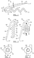
FIG. 1 is a side view of an anchor constructed in accordance with the principles of the present invention; -
FIG. 2 is views of another anchor constructed in accordance with the principles of the present disclosure in an expanded and in a compressed condition; -
FIG. 3 is a view of the lumen of the coil of the device ofFIG. 2 in the compressed condition; -
FIG. 4 is a view of the lumen of the coil of the device ofFIG. 2 in the expanded condition; -
FIG. 5 is a view of the device ofFIG. 2 disposed about an elongate member of a medical device (such as a strut) in a compressed and in an expanded condition; -
FIG. 6 is a view of a plurality of anchors formed in accordance with an embodiment of the present disclosure disposed on an end ring for a stent graft; -
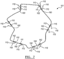
FIG. 7 is a view of a plurality of anchors welded to a stent ring by a tack weld; -
FIG. 8 is an environmental view of a plurality of anchors disposed about an end ring of a stent graft in accordance with an embodiment of the present disclosure; -
FIG. 9 is a view of the stent graft shown inFIG. 8 disposed in a body vessel; -
FIG. 10A is a side view of an anchor assembly including a spacer in accordance with an aspect of the present disclosure; -
FIG. 10B is a cutaway view of the spacer ofFIG. 10A ; and -
FIG. 10C is a side view of the spacer ofFIG. 10A . - The drawings are purely schematic illustrations of various aspects of the invention and are not necessarily to scale, unless expressly stated.
- The terms "substantially" or "about" used herein with reference to a quantity includes variations in the recited quantity that are equivalent to the quantity recited, such as an amount that is equivalent to the quantity recited for an intended purpose or function. "Substantially" or derivatives thereof will be understood to mean significantly or in large part. When used in the context of a numerical value or range set forth, "about" or "substantially" means a variation of ±15%, or less, of the numerical value. For example, a value differing by ±15%, ±14%, ±10%, or ±5%, among others, would satisfy the definition of "about."
- In a first aspect, an
anchor 10 for a medical device is illustrated inFIG. 1 . Theanchor 10 is integrally constructed of a single segment of wire, and includes a coil 12, aturn 14 leading into abend 15, and abarb 16. The coil 12 may be a coarse pitch coil. Theturn 14 joins the coil 12 to thebarb 16, and is formed from a portion along the length of the wire used to make theanchor 10 which lies between thefirst end 13 and thesecond end 17. - The
barb 16 may be sharpened, yielding apointed end 18. However, in some embodiments, thebarb 16 may be made of a thin enough wire to act as the barb without further sharpening. Thebarb 16 is a structure that is capable of engaging the wall of a body passage and anchoring the device therein. Thebarb 16 may be a substantially straight section of wire, or may be have a gentle bend or slight angle, so long as theanchor 10 is still capable of holding a the medical device within the body passage. - If sharpened, the point of
pointed end 18 may comprise a bevel and/or may be formed, such as by a cut, such that it has a smooth and continuous termination. This design serves to tighten the hold on the tissue into which thepointed end 18 is to be inserted. In the embodiment shown inFIG. 1 , theangle 19 formed between thebarb 16 and theface 21 generated by the cut is about 10 degrees, but may be from about 2.5 degrees to about 30 degrees, or from about 5 degrees to about 20 degrees, or from about 7.5 degrees to about 15 degrees. - Because of the
turn 14, thepointed end 18 points back towardfirst end 13. This results in thesecond end 17 being proximate thefirst end 13. In some instances, thesecond end 17 may be closer to thefirst end 13 than it is to the apex 24, which, in the illustrated embodiment, is positioned at thetransition point 22loop 14 and bend 15 of theanchor 10. This construction can result in lengthening and tightening of the coil 12 around the structure about which the coil 12 is disposed, such as a wire strut of a medical device. When used as an anchoring portion of a medical device, hemodynamic forces cause tightening of the grip of theanchor 10 on the strut to which the anchor is attached. That is, when force pushes in a direction that would otherwise dislodge the device from the tissue, the coil 12 reacts by stretching and as a result tightening around the structure on which it is disposed. Theturn 14 and bend 15 also allow for ease in manufacture of theanchor 10, and permit it to be made unitarily, from a single piece of precursor wire, such as a shape memory wire. Thebend 15 also causes thebarb 16 of theanchor 10 to lie tangent a strut to which theanchor 10 is fixed. - In one embodiment, the coil 12 has a first helical handedness and the turn has a second helical handedness which is opposite the first helical handedness. The handedness of a helix may be determined by viewing the helix, or coil, down the helical axis around which it winds. In the case of the present disclosure, the handedness of the coil is defined by the direction in which the coil winds when viewed down the helical axis with the
first end 13 closest the viewer. If the coil extends clockwise, it is a right-handed helix; if it extends counterclockwise, its handedness is instead left-handed. - In an
anchor 10 having a right-handed coil 12, theturn 14 would reverse and be a left-handed turn. In ananchor 10 having a left-handed coil 12, theturn 14 would instead be a right-handed turn. The change in rotational direction between thecoil windings 11 and theturn 14 provides an effective location for a point of resistance to force directed in such a way that would otherwise compress the coil 12, thereby defining a second end to the coil 12 at the position where theturn 14 begins. The coil 12 has a coil length between thefirst end 13 of the anchor and the transition point at the interface of the coil 12 and theturn 14. Theturn 14 may proceed for at least about 90 degrees rotationally, in some embodiments representing a turn of about 135 degrees, or about 180 degrees, or about 225 degrees, or about 270 degrees, or about 315 degrees, or about 360 degrees. - The measurements of portions of the
anchor 10 will vary based on its usage. In one example, the length of thebarb 16, from thesecond end 17 to the end of thebend 15 attransition point 23, may be about 5 millimeters (mm). The uncompressed length of the coil 12 between first end 133 andtransition point 22 may be about 4 mm in thisanchor 10, with a helical pitch (that is, the linear distance between corresponding portions of consecutive windings 11) of 1.5 mm. Thebarb 16 may be angled at about 15 degrees relative to the helical axis of coil 12. Such ananchor 10 may be made of a shape memory alloy, such as a nickel-titanium alloy, which is a wire, the wire having a diameter of about 0.012 inch (0.3048 mm.) In one embodiment, the coil 12 may have a length which is at least double its pitch, but this value may be varied as long as a friction fit between the anchor and the medical device body may be maintained. - Instead of a shape memory alloy, the anchor of the present disclosure may be made of or include stainless steel, or titanium. The anchor may be made of another biocompatible metal and have a coating to inhibit corrosion thereof.
- Turning now to
FIG. 2 , it can be seen that theanchor 110 can have a different number ofwindings 111 in different embodiments. For example, inFIG. 1 , the coil 12 is a coarse pitch coil which has between two and threefull windings 11, whereas inFIG. 2 , the number ofwindings 111 is between 6 and 7. The number of windings may be keyed to the length of the strut of the device to which it will be attached, with a longer coil being employed where there is a longer space to do so. In some cases, the number of coil windings may be between 1.5 and 12 windings. In some embodiments it will be preferred to have between 2 and 4 windings, or between 2 and 3 windings. - The views of
FIG. 2 show theanchor 110 with thecoil 112 in one instance in a longitudinally expanded (or relaxed)state 120, and in a longitudinallycompressed configuration 130. Thecoil 112 has spring-like properties and favors the expandedstate 120 when at rest. Compression of thecoil 112 in the longitudinal or axial dimension, such as by the application of aforce 132, causes the inner diameter of thecoil 112 to increase. -
FIG. 3 and 4 illustrate the consequences of compression on the inner diameter of thecoil 112.FIG. 4 shows thecoil 112 in its at-rest, longitudinally-expandedconfiguration 120. Thecoil 112 defines aluminal space 140 having a first diameter 142 when at rest. When thecoil 112 is compressed, the inner diameter increases, as is seen inFIG. 3 , as do the dimensions of theluminal space 150. InFIG. 3 , the size of theluminal space 140 is shown for reference within longitudinally compressedluminal space 150. The secondinner diameter 152 in this instance is larger than the first inner diameter 142. - The spring-like behavior of the
coil 112 and change in diameter allows for thecoil 112 of theanchor 110 to be sized to fit about a wire portion of a medical device. Theanchor 110 is maintained on the strut by a friction fit or an interference fit. That is, no adhesive, welding, soldering, crimping, or any other attachment mechanism is required to maintain the position of theanchor 110 on the medical device. It can be said that the anchor lacks such a connection to the body of the medical device by any of these means. Such a mechanism of attachment may provide a mechanical advantage, as connection methods such as soldering can change stress properties, and welding can be a technical challenge with shape memory metal components. Notably, the use of a friction fit allows for both anchor and strut to be made of a shape memory metal. Joining two pieces of shape memory material, particularly nickel-titanium alloys, can be achieved by soldering, but doing so changes the mechanical characteristics of the metal components, and soldering can expose workers to toxic chemical byproducts. The simpler workflow of creating a friction fit avoids these potential hazards. Moreover, the use of a friction fit in this way permits the joining of an anchor made from a segment of nickel-titanium (or another metal) wire to a strut which is also made of nickel-titanium wire. When wire is employed rather than cannula cutting, the cost of manufacture decreases. -
FIG. 5 illustrates theanchor 110 in its longitudinally compressedstate 130 and its longitudinally expandedstate 120 when placed about astrut 160 of a medical device to achieve the aforementioned friction fit. Thecoil 112 of theanchor 110 has an inner diameter which is smaller than the diameter of thestrut 160 of the medical device. For instance, if the diameter of thestrut 160 is about 0.020 inch, the nominal diameter of thecoil 112 might be about 0.016 inch. The nominal diameter of the coil may be about 50% to about 99% the diameter of the strut, or about 60% to about 95% the diameter of the strut, or about 70% to about 90% of the diameter of the strut, or about 75% to about 85% the diameter of the strut, or about 77.5% to about 82.5% the diameter of the strut, or about 80% the diameter of the strut, in order to achieve a good fit. -
FIGs. 10A illustrates a portion of ananchor assembly 180 which includes ananchor 110 as described previously, as well as aspacer 175 fit betweenwindings 111 of thecoil 112. Thespacer 175 may be a polymer or metal component that fits, at least in part, between windings in the longitudinal dimension, and assists in retaining the shape and configuration of thecoil 112, inhibiting external forces from compressing thecoil 112, causing theanchor 110 to lose its grip on the strut to which it is attached. Thespacer 175 extends from a first end 178 to a second end 179, and has anouter surface 176 and aninner surface 177 opposite theouter surface 176. Theinner surface 177 may contact the strut of the medical device. In some circumstances, it may be desirable to employ asingle spacer 175; in other aspects, a plurality ofspacers 177 may be employed. Either of the first end 178 and the second end 179 may extend beyond the ends of thecoil 112, or, as shown inFIG. 10A , the first end 178 and the second end 179 may contact thecoil 112. Thespacer 175 has a general spiral shape. - The
anchor 110 may be affixed to thestrut 160 by axial compression of the coil and releasing compression over a section of thestrut 160. Axial compression results in an increase in the inner diameter to the point where thestrut 160 can be inserted. When compression is released, the coil spring exerts an inward radial force when elongating proportional to the change in coil pitch (that is, the more thecoil 112 elongates after compression is released, the more inward force is exerted), thereby affixing theanchor 110 to thestrut 160. Thebarb 116 then protrudes tangent to thestrut 160.FIG. 6 illustratesmultiple anchors 110 attached to a wire in this way. Such a configuration could be employed in, for instance, an end ring of a stent graft. -
FIG. 7 illustrates another way of fixing ananchor 110 to astrut 160. In this case, thecoil 112 is welded to thestrut 160, such as by aweld 162, which may be a tack weld at or near the extreme end of the coil 112 (that is, the end of thecoil 112 that is furthest from the turn and the bend.) Such a weld may reduce the chances that a barb be twisted during deployment. In one embodiment, theweld 162 joins the very end of thecoil 112 to thestrut 160. In another embodiment, theweld 162 may not join the end of thecoil 112 to thestrut 160, but rather a portion of thecoil 112 proximate the end. Theweld 162 may fix less than 10%, or less than 5%, or less than 2%, or less than 1% of the length of thecoil 112 to thestrut 160. Theweld 162 is formed such that thecoil 112 is still able to stretch or contract in response to forces applied thereto during delivery and/or when deployed. -
FIG. 8 is an environmental view of a plurality ofanchors 210 fixed to astent graft 200. Theanchors 210 are disposed at aproximal end 202 of thestent graft 200, but thebarb 218 of each anchor points toward thedistal end 206. Thebend 215 of theanchor 210 represents the proximal-most portion of theanchor 210 when disposed on the end ring. Theanchors 210 are fixed with thecoils 212 disposed about thestruts 260 of theend ring 270 of thestent graft 200. Distal theend ring 270 are further stent rings 290 supportinggraft material 280. -
FIG. 9 depicts thestent graft 200 deployed to alumen 292 of a body vessel V. Thebarbs 218 of theanchors 210 penetrate the vessel wall, still primarily pointing distally while attached to theproximal end 202 of thestent graft 200. Thehemodynamic forces 272 on thestent graft 200 that resist the fixation force of thebarbs 218 will result in a moment about the barb which acts to further constrict thecoil 212 about thestrut 260 ofend ring 270. The combined force of the shape set coil and twisting load due to fixation will provide the requisite resistance to migration, maintaining thestent graft 200 in the location to which it was originally deployed. - Disclosed herein is an anchor for use with a medical device. The anchor includes a coil, a barb, and a turn connecting the coil to the barb. The anchor may be made of a shape memory material. The coil may have a first handedness, and the turn may have a second handedness opposite the first handedness. The anchor may be attached to the medical device by a friction fit, in some cases without being attached by welding, soldering, adhesive, or crimping. In various embodiments describe the possibility of a tightening coil has been discussed, and while it may be advantageous to use such a construction embodiments may be provided without it. Although the embodiments illustrated depict stent grafts, the anchors of the present disclosure could be employed in a variety of medical devices that might be advantageously constructed of shape memory material, particularly shape memory wires. These include, but are not limited to, bare metal stents, occlusion devices, and intravascular filters.
- Likewise, although the anchors of the present disclosure have only been depicted as being fixed to the end ring of a stent graft, anchors of the presently-disclosed design might be affixed anywhere along the length of a strut or a device.
- As a person skilled in the art will readily appreciate, the above description is only meant as an illustration of implementation of the principles this application. This description is not intended to limit the scope of this application in that the system is susceptible to modification, variation and change, without departing from the spirit of this application, as defined in the following claims.
Claims (15)
- A medical device for implantation into a body passage, the medical device comprising:at least one elongate member; andan anchor attached to the elongate member, the anchor having a first end and extending to a second end and comprising:a turn of at least 90 degrees and a bend, the turn and the bend connecting the coil to the barb, such that the barb and the longitudinal axis of the coil define an acute angle therebetween.a coil defining a longitudinal axis therethrough, at least a portion of the coil surrounding the elongate member and configured so that when the coil is stretched longitudinally, it grips the elongate member more tightly;a barb including the second end; and
- The medical device of claim 1, wherein the medical device comprises a stent.
- The medical device of any preceding claim, wherein the anchor is fixed to the elongate member by a friction fit.
- The medical device of any preceding claim, wherein the anchor is disposed at a proximal end of the medical device, and the second end is directed toward a distal end of the medical device.
- The medical device of any preceding claim, wherein the anchor lacks a fixed connection to the elongate member by any of a weld, a solder joint, and an adhesive.
- The medical device of any of claims 1 to 4, wherein the coil is fixed to the elongate member by a weld.
- The medical device of any preceding claim, wherein the coil is compressed longitudinally to fit the anchor to the elongate member, for example wherein the coil lacks a crimp about the elongate member.
- The medical device of any preceding claim, where the coil has a first handedness, and the turn has a second handedness opposite the first handedness.
- The medical device of any preceding claim, wherein in the coil has an inner diameter in a free condition from about 50% to about 99% the diameter of the elongate member.
- The medical device of any preceding claim, wherein the coil comprises a plurality of windings, the medical device further comprising a spacer disposed between at least two windings in a longitudinal dimension.
- An anchor for a medical device, the anchor having a first end and extending to a second end and comprising:a coil defining a longitudinal axis therethrough, at least a portion of the coil configured to be disposed about an elongate member of the medical device;a barb including the second end; anda turn of at least 90 degrees and a bend, the turn and the bend connecting the coil to the barb, such that the barb and the longitudinal axis of the coil define an acute angle therebetween, and when the coil is stretched longitudinally, it grips the elongate member more tightly .
- The anchor of any preceding claim , wherein the second end defines a point, for example wherein the point is defined by a cut made about 5 degrees to about 15 degrees relative to a longitudinal axis of the barb.
- The anchor of claim 12, wherein the coil is movable between an expanded diameter and a compressed diameter, and is heat set to define a remembered condition at the compressed diameter, for example wherein the anchor comprises a shape memory material.
- The anchor of claim 11, wherein the coil has a first handedness, and the turn has a second handedness opposite the first handedness.
- The anchor of claim 13, wherein in the expanded configuration, the coil has a length at least double a pitch of the coil.
Applications Claiming Priority (1)
| Application Number | Priority Date | Filing Date | Title |
|---|---|---|---|
| US201862711900P | 2018-07-30 | 2018-07-30 |
Publications (2)
| Publication Number | Publication Date |
|---|---|
| EP3603583A1 true EP3603583A1 (en) | 2020-02-05 |
| EP3603583B1 EP3603583B1 (en) | 2022-11-30 |
Family
ID=67513433
Family Applications (1)
| Application Number | Title | Priority Date | Filing Date |
|---|---|---|---|
| EP19189220.7A Active EP3603583B1 (en) | 2018-07-30 | 2019-07-30 | Spring barb for medical device |
Country Status (2)
| Country | Link |
|---|---|
| US (1) | US11497632B2 (en) |
| EP (1) | EP3603583B1 (en) |
Families Citing this family (1)
| Publication number | Priority date | Publication date | Assignee | Title |
|---|---|---|---|---|
| CN115024782B (en) * | 2022-05-05 | 2025-02-28 | 上海形状记忆合金材料有限公司 | Hook and blocking device |
Citations (4)
| Publication number | Priority date | Publication date | Assignee | Title |
|---|---|---|---|---|
| US6520974B2 (en) * | 1997-06-30 | 2003-02-18 | Eva Corporation | Surgical fastener |
| US20080033534A1 (en) * | 2002-05-16 | 2008-02-07 | Cook Incorporated | Flexible Barb for Anchoring a Prosthesis |
| US20090171442A1 (en) * | 2007-12-27 | 2009-07-02 | Cook Incorporated | Z-stent with incorporated barbs |
| EP2331027A1 (en) * | 2008-08-29 | 2011-06-15 | Med Institute, Inc. | Barbed anchors for implantable medical device |
Family Cites Families (12)
| Publication number | Priority date | Publication date | Assignee | Title |
|---|---|---|---|---|
| US6458092B1 (en) * | 1998-09-30 | 2002-10-01 | C. R. Bard, Inc. | Vascular inducing implants |
| WO2003096935A1 (en) | 2002-05-16 | 2003-11-27 | Cook Incorporated | Flexible barb for anchoring a prosthesis |
| EP1706070B1 (en) | 2004-01-20 | 2011-02-23 | Cook Incorporated | Multiple stitches for attaching stent to graft |
| US8348988B2 (en) | 2004-01-20 | 2013-01-08 | Cook Medical Technologies, LLC | Endoluminal prosthetic device |
| US7572289B2 (en) | 2004-01-27 | 2009-08-11 | Med Institute, Inc. | Anchoring barb for attachment to a medical prosthesis |
| US9237959B2 (en) | 2007-08-17 | 2016-01-19 | Cook Medical Technologies Llc | Stent and barb |
| US8696739B2 (en) * | 2008-08-29 | 2014-04-15 | Cook Medical Technologies Llc | Barbed anchor |
| EP2358300B1 (en) | 2008-12-17 | 2016-02-17 | Cook Medical Technologies LLC | Barb for anchoring an implantable medical device within a body vessel |
| GB2472602B (en) * | 2009-08-11 | 2011-12-14 | Cook Medical Technologies Llc | Medical device and method of manufacturing same |
| GB2472603B (en) | 2009-08-11 | 2011-12-14 | Cook Medical Technologies Llc | Implantable medical device |
| US8834553B2 (en) | 2009-09-11 | 2014-09-16 | Gi Dynamics, Inc. | Anchors with biodegradable constraints |
| EP2600794B1 (en) * | 2010-08-03 | 2015-12-09 | Cook Medical Technologies LLC | Blood perfusion device |
-
2019
- 2019-07-29 US US16/524,999 patent/US11497632B2/en active Active
- 2019-07-30 EP EP19189220.7A patent/EP3603583B1/en active Active
Patent Citations (4)
| Publication number | Priority date | Publication date | Assignee | Title |
|---|---|---|---|---|
| US6520974B2 (en) * | 1997-06-30 | 2003-02-18 | Eva Corporation | Surgical fastener |
| US20080033534A1 (en) * | 2002-05-16 | 2008-02-07 | Cook Incorporated | Flexible Barb for Anchoring a Prosthesis |
| US20090171442A1 (en) * | 2007-12-27 | 2009-07-02 | Cook Incorporated | Z-stent with incorporated barbs |
| EP2331027A1 (en) * | 2008-08-29 | 2011-06-15 | Med Institute, Inc. | Barbed anchors for implantable medical device |
Also Published As
| Publication number | Publication date |
|---|---|
| US11497632B2 (en) | 2022-11-15 |
| EP3603583B1 (en) | 2022-11-30 |
| US20200030123A1 (en) | 2020-01-30 |
Similar Documents
| Publication | Publication Date | Title |
|---|---|---|
| US20040015229A1 (en) | Vascular stent with radiopaque markers | |
| JP4624779B2 (en) | Flexible “kaeshi” that locks the prosthesis | |
| US6451025B1 (en) | Prosthesis and method for deployment within a body lumen | |
| US20230146457A1 (en) | Devices and Methods for Securing Medical Devices within an Anatomy | |
| JP2005536304A (en) | Helical stent with improved flexibility and expandability | |
| EP3510976B1 (en) | Barbed wire stent | |
| US8747457B2 (en) | Medical device and method of manufacturing same | |
| EP3603583B1 (en) | Spring barb for medical device | |
| US20160113753A1 (en) | Implantable medical device exhibiting diminishing radial force | |
| WO2022152363A1 (en) | Embolisation system for promoting blood clot formation | |
| US11331207B2 (en) | Stent | |
| HK40017558A (en) | Devices for securing medical devices within an anatomy | |
| HK1205444B (en) | Devices for securing medical devices within an anatomy |
Legal Events
| Date | Code | Title | Description |
|---|---|---|---|
| PUAI | Public reference made under article 153(3) epc to a published international application that has entered the european phase |
Free format text: ORIGINAL CODE: 0009012 |
|
| STAA | Information on the status of an ep patent application or granted ep patent |
Free format text: STATUS: THE APPLICATION HAS BEEN PUBLISHED |
|
| AK | Designated contracting states |
Kind code of ref document: A1 Designated state(s): AL AT BE BG CH CY CZ DE DK EE ES FI FR GB GR HR HU IE IS IT LI LT LU LV MC MK MT NL NO PL PT RO RS SE SI SK SM TR |
|
| AX | Request for extension of the european patent |
Extension state: BA ME |
|
| STAA | Information on the status of an ep patent application or granted ep patent |
Free format text: STATUS: REQUEST FOR EXAMINATION WAS MADE |
|
| 17P | Request for examination filed |
Effective date: 20200805 |
|
| RBV | Designated contracting states (corrected) |
Designated state(s): AL AT BE BG CH CY CZ DE DK EE ES FI FR GB GR HR HU IE IS IT LI LT LU LV MC MK MT NL NO PL PT RO RS SE SI SK SM TR |
|
| STAA | Information on the status of an ep patent application or granted ep patent |
Free format text: STATUS: EXAMINATION IS IN PROGRESS |
|
| 17Q | First examination report despatched |
Effective date: 20201208 |
|
| GRAP | Despatch of communication of intention to grant a patent |
Free format text: ORIGINAL CODE: EPIDOSNIGR1 |
|
| STAA | Information on the status of an ep patent application or granted ep patent |
Free format text: STATUS: GRANT OF PATENT IS INTENDED |
|
| RIC1 | Information provided on ipc code assigned before grant |
Ipc: A61B 17/00 20060101ALN20220516BHEP Ipc: A61B 17/12 20060101ALN20220516BHEP Ipc: A61F 2/01 20060101ALN20220516BHEP Ipc: A61F 2/07 20130101ALN20220516BHEP Ipc: A61F 2/848 20130101AFI20220516BHEP |
|
| INTG | Intention to grant announced |
Effective date: 20220609 |
|
| RIN1 | Information on inventor provided before grant (corrected) |
Inventor name: BAXTER, CHARLES Inventor name: BRADWAY, RYAN |
|
| GRAS | Grant fee paid |
Free format text: ORIGINAL CODE: EPIDOSNIGR3 |
|
| GRAA | (expected) grant |
Free format text: ORIGINAL CODE: 0009210 |
|
| STAA | Information on the status of an ep patent application or granted ep patent |
Free format text: STATUS: THE PATENT HAS BEEN GRANTED |
|
| AK | Designated contracting states |
Kind code of ref document: B1 Designated state(s): AL AT BE BG CH CY CZ DE DK EE ES FI FR GB GR HR HU IE IS IT LI LT LU LV MC MK MT NL NO PL PT RO RS SE SI SK SM TR |
|
| REG | Reference to a national code |
Ref country code: CH Ref legal event code: EP Ref country code: GB Ref legal event code: FG4D |
|
| REG | Reference to a national code |
Ref country code: AT Ref legal event code: REF Ref document number: 1534110 Country of ref document: AT Kind code of ref document: T Effective date: 20221215 |
|
| REG | Reference to a national code |
Ref country code: IE Ref legal event code: FG4D |
|
| REG | Reference to a national code |
Ref country code: DE Ref legal event code: R096 Ref document number: 602019022449 Country of ref document: DE |
|
| REG | Reference to a national code |
Ref country code: LT Ref legal event code: MG9D |
|
| REG | Reference to a national code |
Ref country code: NL Ref legal event code: MP Effective date: 20221130 |
|
| PG25 | Lapsed in a contracting state [announced via postgrant information from national office to epo] |
Ref country code: SE Free format text: LAPSE BECAUSE OF FAILURE TO SUBMIT A TRANSLATION OF THE DESCRIPTION OR TO PAY THE FEE WITHIN THE PRESCRIBED TIME-LIMIT Effective date: 20221130 Ref country code: PT Free format text: LAPSE BECAUSE OF FAILURE TO SUBMIT A TRANSLATION OF THE DESCRIPTION OR TO PAY THE FEE WITHIN THE PRESCRIBED TIME-LIMIT Effective date: 20230331 Ref country code: NO Free format text: LAPSE BECAUSE OF FAILURE TO SUBMIT A TRANSLATION OF THE DESCRIPTION OR TO PAY THE FEE WITHIN THE PRESCRIBED TIME-LIMIT Effective date: 20230228 Ref country code: LT Free format text: LAPSE BECAUSE OF FAILURE TO SUBMIT A TRANSLATION OF THE DESCRIPTION OR TO PAY THE FEE WITHIN THE PRESCRIBED TIME-LIMIT Effective date: 20221130 Ref country code: FI Free format text: LAPSE BECAUSE OF FAILURE TO SUBMIT A TRANSLATION OF THE DESCRIPTION OR TO PAY THE FEE WITHIN THE PRESCRIBED TIME-LIMIT Effective date: 20221130 Ref country code: ES Free format text: LAPSE BECAUSE OF FAILURE TO SUBMIT A TRANSLATION OF THE DESCRIPTION OR TO PAY THE FEE WITHIN THE PRESCRIBED TIME-LIMIT Effective date: 20221130 |
|
| REG | Reference to a national code |
Ref country code: AT Ref legal event code: MK05 Ref document number: 1534110 Country of ref document: AT Kind code of ref document: T Effective date: 20221130 |
|
| PG25 | Lapsed in a contracting state [announced via postgrant information from national office to epo] |
Ref country code: RS Free format text: LAPSE BECAUSE OF FAILURE TO SUBMIT A TRANSLATION OF THE DESCRIPTION OR TO PAY THE FEE WITHIN THE PRESCRIBED TIME-LIMIT Effective date: 20221130 Ref country code: PL Free format text: LAPSE BECAUSE OF FAILURE TO SUBMIT A TRANSLATION OF THE DESCRIPTION OR TO PAY THE FEE WITHIN THE PRESCRIBED TIME-LIMIT Effective date: 20221130 Ref country code: LV Free format text: LAPSE BECAUSE OF FAILURE TO SUBMIT A TRANSLATION OF THE DESCRIPTION OR TO PAY THE FEE WITHIN THE PRESCRIBED TIME-LIMIT Effective date: 20221130 Ref country code: IS Free format text: LAPSE BECAUSE OF FAILURE TO SUBMIT A TRANSLATION OF THE DESCRIPTION OR TO PAY THE FEE WITHIN THE PRESCRIBED TIME-LIMIT Effective date: 20230330 Ref country code: HR Free format text: LAPSE BECAUSE OF FAILURE TO SUBMIT A TRANSLATION OF THE DESCRIPTION OR TO PAY THE FEE WITHIN THE PRESCRIBED TIME-LIMIT Effective date: 20221130 Ref country code: GR Free format text: LAPSE BECAUSE OF FAILURE TO SUBMIT A TRANSLATION OF THE DESCRIPTION OR TO PAY THE FEE WITHIN THE PRESCRIBED TIME-LIMIT Effective date: 20230301 |
|
| PG25 | Lapsed in a contracting state [announced via postgrant information from national office to epo] |
Ref country code: NL Free format text: LAPSE BECAUSE OF FAILURE TO SUBMIT A TRANSLATION OF THE DESCRIPTION OR TO PAY THE FEE WITHIN THE PRESCRIBED TIME-LIMIT Effective date: 20221130 |
|
| P01 | Opt-out of the competence of the unified patent court (upc) registered |
Effective date: 20230602 |
|
| PG25 | Lapsed in a contracting state [announced via postgrant information from national office to epo] |
Ref country code: SM Free format text: LAPSE BECAUSE OF FAILURE TO SUBMIT A TRANSLATION OF THE DESCRIPTION OR TO PAY THE FEE WITHIN THE PRESCRIBED TIME-LIMIT Effective date: 20221130 Ref country code: RO Free format text: LAPSE BECAUSE OF FAILURE TO SUBMIT A TRANSLATION OF THE DESCRIPTION OR TO PAY THE FEE WITHIN THE PRESCRIBED TIME-LIMIT Effective date: 20221130 Ref country code: EE Free format text: LAPSE BECAUSE OF FAILURE TO SUBMIT A TRANSLATION OF THE DESCRIPTION OR TO PAY THE FEE WITHIN THE PRESCRIBED TIME-LIMIT Effective date: 20221130 Ref country code: DK Free format text: LAPSE BECAUSE OF FAILURE TO SUBMIT A TRANSLATION OF THE DESCRIPTION OR TO PAY THE FEE WITHIN THE PRESCRIBED TIME-LIMIT Effective date: 20221130 Ref country code: CZ Free format text: LAPSE BECAUSE OF FAILURE TO SUBMIT A TRANSLATION OF THE DESCRIPTION OR TO PAY THE FEE WITHIN THE PRESCRIBED TIME-LIMIT Effective date: 20221130 Ref country code: AT Free format text: LAPSE BECAUSE OF FAILURE TO SUBMIT A TRANSLATION OF THE DESCRIPTION OR TO PAY THE FEE WITHIN THE PRESCRIBED TIME-LIMIT Effective date: 20221130 |
|
| PG25 | Lapsed in a contracting state [announced via postgrant information from national office to epo] |
Ref country code: SK Free format text: LAPSE BECAUSE OF FAILURE TO SUBMIT A TRANSLATION OF THE DESCRIPTION OR TO PAY THE FEE WITHIN THE PRESCRIBED TIME-LIMIT Effective date: 20221130 Ref country code: AL Free format text: LAPSE BECAUSE OF FAILURE TO SUBMIT A TRANSLATION OF THE DESCRIPTION OR TO PAY THE FEE WITHIN THE PRESCRIBED TIME-LIMIT Effective date: 20221130 |
|
| REG | Reference to a national code |
Ref country code: DE Ref legal event code: R097 Ref document number: 602019022449 Country of ref document: DE |
|
| PLBE | No opposition filed within time limit |
Free format text: ORIGINAL CODE: 0009261 |
|
| STAA | Information on the status of an ep patent application or granted ep patent |
Free format text: STATUS: NO OPPOSITION FILED WITHIN TIME LIMIT |
|
| 26N | No opposition filed |
Effective date: 20230831 |
|
| PG25 | Lapsed in a contracting state [announced via postgrant information from national office to epo] |
Ref country code: SI Free format text: LAPSE BECAUSE OF FAILURE TO SUBMIT A TRANSLATION OF THE DESCRIPTION OR TO PAY THE FEE WITHIN THE PRESCRIBED TIME-LIMIT Effective date: 20221130 |
|
| PG25 | Lapsed in a contracting state [announced via postgrant information from national office to epo] |
Ref country code: MC Free format text: LAPSE BECAUSE OF FAILURE TO SUBMIT A TRANSLATION OF THE DESCRIPTION OR TO PAY THE FEE WITHIN THE PRESCRIBED TIME-LIMIT Effective date: 20221130 |
|
| PG25 | Lapsed in a contracting state [announced via postgrant information from national office to epo] |
Ref country code: MC Free format text: LAPSE BECAUSE OF FAILURE TO SUBMIT A TRANSLATION OF THE DESCRIPTION OR TO PAY THE FEE WITHIN THE PRESCRIBED TIME-LIMIT Effective date: 20221130 |
|
| REG | Reference to a national code |
Ref country code: CH Ref legal event code: PL |
|
| REG | Reference to a national code |
Ref country code: BE Ref legal event code: MM Effective date: 20230731 |
|
| PG25 | Lapsed in a contracting state [announced via postgrant information from national office to epo] |
Ref country code: LU Free format text: LAPSE BECAUSE OF NON-PAYMENT OF DUE FEES Effective date: 20230730 |
|
| PG25 | Lapsed in a contracting state [announced via postgrant information from national office to epo] |
Ref country code: LU Free format text: LAPSE BECAUSE OF NON-PAYMENT OF DUE FEES Effective date: 20230730 |
|
| PG25 | Lapsed in a contracting state [announced via postgrant information from national office to epo] |
Ref country code: CH Free format text: LAPSE BECAUSE OF NON-PAYMENT OF DUE FEES Effective date: 20230731 |
|
| PG25 | Lapsed in a contracting state [announced via postgrant information from national office to epo] |
Ref country code: IT Free format text: LAPSE BECAUSE OF FAILURE TO SUBMIT A TRANSLATION OF THE DESCRIPTION OR TO PAY THE FEE WITHIN THE PRESCRIBED TIME-LIMIT Effective date: 20221130 Ref country code: FR Free format text: LAPSE BECAUSE OF NON-PAYMENT OF DUE FEES Effective date: 20230731 Ref country code: BE Free format text: LAPSE BECAUSE OF NON-PAYMENT OF DUE FEES Effective date: 20230731 |
|
| PG25 | Lapsed in a contracting state [announced via postgrant information from national office to epo] |
Ref country code: BG Free format text: LAPSE BECAUSE OF FAILURE TO SUBMIT A TRANSLATION OF THE DESCRIPTION OR TO PAY THE FEE WITHIN THE PRESCRIBED TIME-LIMIT Effective date: 20221130 |
|
| PG25 | Lapsed in a contracting state [announced via postgrant information from national office to epo] |
Ref country code: BG Free format text: LAPSE BECAUSE OF FAILURE TO SUBMIT A TRANSLATION OF THE DESCRIPTION OR TO PAY THE FEE WITHIN THE PRESCRIBED TIME-LIMIT Effective date: 20221130 |
|
| PG25 | Lapsed in a contracting state [announced via postgrant information from national office to epo] |
Ref country code: CY Free format text: LAPSE BECAUSE OF FAILURE TO SUBMIT A TRANSLATION OF THE DESCRIPTION OR TO PAY THE FEE WITHIN THE PRESCRIBED TIME-LIMIT; INVALID AB INITIO Effective date: 20190730 |
|
| PG25 | Lapsed in a contracting state [announced via postgrant information from national office to epo] |
Ref country code: HU Free format text: LAPSE BECAUSE OF FAILURE TO SUBMIT A TRANSLATION OF THE DESCRIPTION OR TO PAY THE FEE WITHIN THE PRESCRIBED TIME-LIMIT; INVALID AB INITIO Effective date: 20190730 |
|
| PGFP | Annual fee paid to national office [announced via postgrant information from national office to epo] |
Ref country code: DE Payment date: 20250728 Year of fee payment: 7 |
|
| PGFP | Annual fee paid to national office [announced via postgrant information from national office to epo] |
Ref country code: GB Payment date: 20250722 Year of fee payment: 7 |
|
| PGFP | Annual fee paid to national office [announced via postgrant information from national office to epo] |
Ref country code: IE Payment date: 20250718 Year of fee payment: 7 |
|
| PG25 | Lapsed in a contracting state [announced via postgrant information from national office to epo] |
Ref country code: TR Free format text: LAPSE BECAUSE OF FAILURE TO SUBMIT A TRANSLATION OF THE DESCRIPTION OR TO PAY THE FEE WITHIN THE PRESCRIBED TIME-LIMIT Effective date: 20221130 |