EP3603373B1 - Cover attachment for lawnmower cutter housing - Google Patents
Cover attachment for lawnmower cutter housing Download PDFInfo
- Publication number
- EP3603373B1 EP3603373B1 EP19179685.3A EP19179685A EP3603373B1 EP 3603373 B1 EP3603373 B1 EP 3603373B1 EP 19179685 A EP19179685 A EP 19179685A EP 3603373 B1 EP3603373 B1 EP 3603373B1
- Authority
- EP
- European Patent Office
- Prior art keywords
- belt
- opening
- lawnmower
- cutter
- cutter housing
- Prior art date
- Legal status (The legal status is an assumption and is not a legal conclusion. Google has not performed a legal analysis and makes no representation as to the accuracy of the status listed.)
- Active
Links
Images




Classifications
-
- A—HUMAN NECESSITIES
- A01—AGRICULTURE; FORESTRY; ANIMAL HUSBANDRY; HUNTING; TRAPPING; FISHING
- A01D—HARVESTING; MOWING
- A01D34/00—Mowers; Mowing apparatus of harvesters
- A01D34/01—Mowers; Mowing apparatus of harvesters characterised by features relating to the type of cutting apparatus
- A01D34/412—Mowers; Mowing apparatus of harvesters characterised by features relating to the type of cutting apparatus having rotating cutters
- A01D34/63—Mowers; Mowing apparatus of harvesters characterised by features relating to the type of cutting apparatus having rotating cutters having cutters rotating about a vertical axis
- A01D34/81—Casings; Housings
-
- A—HUMAN NECESSITIES
- A01—AGRICULTURE; FORESTRY; ANIMAL HUSBANDRY; HUNTING; TRAPPING; FISHING
- A01D—HARVESTING; MOWING
- A01D34/00—Mowers; Mowing apparatus of harvesters
- A01D34/01—Mowers; Mowing apparatus of harvesters characterised by features relating to the type of cutting apparatus
- A01D34/412—Mowers; Mowing apparatus of harvesters characterised by features relating to the type of cutting apparatus having rotating cutters
- A01D34/63—Mowers; Mowing apparatus of harvesters characterised by features relating to the type of cutting apparatus having rotating cutters having cutters rotating about a vertical axis
- A01D34/67—Mowers; Mowing apparatus of harvesters characterised by features relating to the type of cutting apparatus having rotating cutters having cutters rotating about a vertical axis hand-guided by a walking operator
- A01D34/68—Mowers; Mowing apparatus of harvesters characterised by features relating to the type of cutting apparatus having rotating cutters having cutters rotating about a vertical axis hand-guided by a walking operator with motor driven cutters or wheels
-
- A—HUMAN NECESSITIES
- A01—AGRICULTURE; FORESTRY; ANIMAL HUSBANDRY; HUNTING; TRAPPING; FISHING
- A01D—HARVESTING; MOWING
- A01D34/00—Mowers; Mowing apparatus of harvesters
- A01D34/01—Mowers; Mowing apparatus of harvesters characterised by features relating to the type of cutting apparatus
- A01D34/412—Mowers; Mowing apparatus of harvesters characterised by features relating to the type of cutting apparatus having rotating cutters
- A01D34/63—Mowers; Mowing apparatus of harvesters characterised by features relating to the type of cutting apparatus having rotating cutters having cutters rotating about a vertical axis
- A01D34/67—Mowers; Mowing apparatus of harvesters characterised by features relating to the type of cutting apparatus having rotating cutters having cutters rotating about a vertical axis hand-guided by a walking operator
- A01D34/68—Mowers; Mowing apparatus of harvesters characterised by features relating to the type of cutting apparatus having rotating cutters having cutters rotating about a vertical axis hand-guided by a walking operator with motor driven cutters or wheels
- A01D34/69—Mowers; Mowing apparatus of harvesters characterised by features relating to the type of cutting apparatus having rotating cutters having cutters rotating about a vertical axis hand-guided by a walking operator with motor driven cutters or wheels with motor driven wheels
-
- A—HUMAN NECESSITIES
- A01—AGRICULTURE; FORESTRY; ANIMAL HUSBANDRY; HUNTING; TRAPPING; FISHING
- A01D—HARVESTING; MOWING
- A01D34/00—Mowers; Mowing apparatus of harvesters
- A01D34/01—Mowers; Mowing apparatus of harvesters characterised by features relating to the type of cutting apparatus
- A01D34/412—Mowers; Mowing apparatus of harvesters characterised by features relating to the type of cutting apparatus having rotating cutters
- A01D34/63—Mowers; Mowing apparatus of harvesters characterised by features relating to the type of cutting apparatus having rotating cutters having cutters rotating about a vertical axis
- A01D34/76—Driving mechanisms for the cutters
- A01D34/78—Driving mechanisms for the cutters electric
-
- A—HUMAN NECESSITIES
- A01—AGRICULTURE; FORESTRY; ANIMAL HUSBANDRY; HUNTING; TRAPPING; FISHING
- A01D—HARVESTING; MOWING
- A01D34/00—Mowers; Mowing apparatus of harvesters
- A01D34/01—Mowers; Mowing apparatus of harvesters characterised by features relating to the type of cutting apparatus
- A01D34/412—Mowers; Mowing apparatus of harvesters characterised by features relating to the type of cutting apparatus having rotating cutters
- A01D34/63—Mowers; Mowing apparatus of harvesters characterised by features relating to the type of cutting apparatus having rotating cutters having cutters rotating about a vertical axis
- A01D34/82—Other details
- A01D34/828—Safety devices
-
- A—HUMAN NECESSITIES
- A01—AGRICULTURE; FORESTRY; ANIMAL HUSBANDRY; HUNTING; TRAPPING; FISHING
- A01D—HARVESTING; MOWING
- A01D2101/00—Lawn-mowers
Definitions
- aspects of the present disclosure relate to power equipment and methods of assembly thereof, and in particular to systems, devices and methods of assembling a lawnmower.
- Lawnmowers offer various options for handling clippings of the cut grass.
- a mulching option restricts the clippings from leaving a cutter housing such that the cutter repeatedly cuts the clippings and reduces their size. The small clippings eventually exit the cutter housing via a lower opening.
- a bagging option utilizes a discharge chute, typically located at a rear of the cutter housing.
- a self-propelled lawnmower may include a single engine that rotationally drives a shaft.
- a cutter may be releasably engaged to the shaft to rotate the cutter for cutting grass.
- a transmission may be coupled to the shaft via a belt to rotate an axle or one or more drive wheels.
- the belt is typically located above the cutter, as disclosed in US2003/182919A1 .
- the belt is typically shielded from the cutter and grass clippings by a belt cover.
- Conventional belt covers may be integrated with a cutter housing. While secure, such integrated belt covers make service of the belt inconvenient.
- the disclosure provides a lawnmower according to claim 1.
- the lawnmower includes a cutter mounted to a shaft oriented in a vertical direction.
- the lawnmower includes a rear axle oriented in a horizontal direction.
- the lawnmower includes a cutter housing defining a lower opening below the cutter, a belt opening between the shaft and the rear axle, and at least one discharge opening.
- the lawnmower includes a belt cover including a ring portion at least partially surrounding the shaft above the cutter and a guard portion extending toward the belt opening.
- the belt cover includes at least one tab that engages a corresponding pocket on the cutter housing adjacent the belt opening.
- the disclosure provides a method of assembling a lawnmower according to claim 14.
- the method includes mounting a motor having a motor shaft on top of a cutter housing, the cutter housing defining a lower opening, a belt opening between the motor shaft and a rear axle, and at least one discharge opening.
- the method includes mounting a belt on the motor shaft and on a transmission coupled to the rear axle.
- the method includes providing a belt cover including a ring portion at least partially surrounding the motor shaft, the belt cover including a guard portion extending rearward toward the belt opening below the belt, wherein the guard portion includes at least one tab extending from a rearward edge.
- the method includes inserting the at least one tab into a corresponding pocket on the cutter housing adjacent the belt opening.
- the method includes securing the ring portion to a bottom surface of the cutter housing with a plurality of fasteners.
- a lawnmower including a belt cover that is releasably coupled to a cutter housing using at least one tab that engages a respective pocket on the cutter housing. The engagement of the tab and the respective pocket prevents the belt cover from moving horiztonally, axially, and vertically.
- the belt cover includes a ring portion that at least partially surrounds a cutter shaft and a guard portion that extends toward the belt opening to shield the belt from the cutter.
- FIG. 1 illustrates an example lawnmower 100.
- the lawnmower 100 may include some components of a conventional lawnmower.
- the lawnmower 100 includes a motor 110, a cutter housing 120, front wheels 122, and rear wheels 124.
- the cutter housing 120 may be generally dome-shaped, defining a volume underneath for cutting grass.
- the cutter housing 120 may be supported on the front wheels 122 and rear wheels 124 such that a bottom edge is elevated and defines a lower opening 126 through which grass may enter the cutter housing.
- the cutter housing 120 may also be described an annular shape that includes a central opening, where the motor 110 is mounted. It should be appreciated that various shapes of lawnmower cutter housings known in the art may be adapted to accommodate a belt cover as discussed in further detail below.
- the lawnmower 100 may also include a handle 150 including controls 154 and a dead-man switch 152 (or operator presence control).
- the controls 154 may control motor speed and/or transmission direction.
- the dead-man switch 152 may stop the motor, cutter, or transmission of the lawnmower 100 when not held by an operator.
- the lawnmower 100 may include a rear cover 140 that may be raised to permit the use of a bagging attachment and lowered when the bagging attachment is not in use.
- the conventional lawnmower components may be arranged or substituted according to other known designs or modified as appropriate for a particular goal.
- the motor 110 may be an electric motor or a gasoline engine.
- FIG. 2 illustrates a longitudinal cross-sectional view of the example lawnmower 100 along the line 2-2.
- the motor 110 includes a shaft 210 that is rotationally driven by the motor 110.
- the shaft 210 may be oriented vertically and extend downward from the motor 110.
- the shaft 210 may rotate a cutter 212 mounted on the shaft 210.
- the cutter 212 may be, for example, a blade or a line.
- the dead-man switch 152 may rotationally couple the cutter 212 to the shaft 210 when the dead-man switch 152 is activated and rotationally decouple the cutter 212 from the shaft 210 when the dead-man switch 152 is released.
- a pulley 230 may be mounted on the shaft 210 and rotationally driven by the motor 110.
- a belt 240 may be mounted on the pulley 230 and connect the pulley 230 to a transmission 250.
- the transmission 250 may releasably couple the belt to one or more rear wheels 124 (e.g., via a rear axle 252), to drive the lawnmower 100 in a forward or reverse direction.
- the controls 154 may control the transmission 250 to provide forward, reverse or neutral drive of the rear wheels 124 via the transmission 250.
- a belt cover 220 may be positioned between the belt 240 and the cutter 212.
- the belt cover 220 may be generally flat and extend horizontally from an area surrounding the shaft 210 toward the transmission 250.
- the belt cover 220 may divide a volume under the cutter housing 120 into a cutting volume including the cutter 212 and a belt volume including the belt 240.
- the belt cover 220 may perform several functions.
- the belt cover 220 may protect the belt 240 and transmissions 250 from the cutter 212 and from debris (e.g., grass clippings) moving within the cutter volume. Without a belt cover 220, the debris may contact the belt 240 or transmission 250 and cause additional wear.
- the debris may stick to the belt 240 or transmission 250 and either lubricate the belt 240, thereby causing slippage, or clog the transmission 250.
- the belt cover 220 may reduce the amount of debris contacting the belt 240 and transmission 250. Additionally, the belt cover 220 may define a shape and aerodynamic properties of the cutting volume. The belt cover 220 may direct the movement of the debris within the cutting volume. In an aspect, the belt cover 220 may direct the debris toward a discharge port or chute, for example, for bagging. In another aspect, the belt cover 220 may block discharge to encourage recirculation of the debris within the cutting volume to reduce debris size for mulching.
- the present disclosure provides for a separate belt cover 220 that is removably coupled to the rear assembly via a plurality of tabs that engage pockets on the rear assembly.
- the disclosed separate belt cover 220 may allow easier access to the belt 240 while providing an effective shield against debris.
- FIGs. 3-7 illustrate an example belt cover 220 and an example rear assembly 300.
- FIG. 3 is a perspective view of the example belt cover 220 mounted to the rear assembly 300.
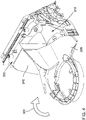
- FIG. 4 is an additional perspective view of the example belt cover 220 and rear assembly 300.
- FIG. 5 is a top view of the example belt cover 220 and rear assembly 300.
- FIG. 6 is a perspective view of the example rear assembly in isolation.
- FIG. 7 is a perspective view of the example belt cover 220 in isolation.
- the rear assembly 300 may form a rear portion of the cutter housing 120.
- the rear assembly 300 may be mounted to a metal dome portion of the cutter housing 120.
- the belt cover 220 and the rear assembly 300 may be separately molded from a high-strength plastic such as, for example, polypropylene, polypropylene high impact copolymers, high-density polyethylene (HDPE), low-density polyethylene (LDPE), acrylonitrile butadiene styrene (ABS), ultra high molecular weight polyethylene (UHMWPE), polycarbonate (PC), polyoxymethylene (POM), Nylon, or a combination thereof.
- a high-strength plastic such as, for example, polypropylene, polypropylene high impact copolymers, high-density polyethylene (HDPE), low-density polyethylene (LDPE), acrylonitrile butadiene styrene (ABS), ultra high molecular weight polyethylene (UHMWPE), polycarbonate (PC), polyoxymethylene (POM), Nylon, or a combination thereof.
- a high-strength plastic such as, for example, poly
- the rear assembly 300 may form a rear wall 302 of the cutting volume.
- the rear wall 302 may include a lower portion 304 that is located below the cutter 212 and an upper portion 306 located above the cutter 212.
- the rear assembly 300 may also support the transmission 250, rear wheels 124, and handle 150 at various locations behind the rear wall 302.
- the rear assembly 300 may include a belt opening 310 that allows the belt 240 to pass through the rear wall to the transmission 250.
- the belt opening 310 may be located above the lower portion 304.
- the rear assembly 300 may include a discharge chute 340 extending through the rear wall 302.
- the discharge chute 340 may be located, for example, above the lower portion 304.
- the discharge chute 340 may share a common wall 308 with the belt opening 310.
- the discharge chute 340 may include a lower surface 342 that inclines upwardly from the lower portion 304 to a rearward edge of the discharge chute 340.
- the cutter 212 may rotate in a clockwise direction 316 when viewed from the top.
- the discharge chute 340 may be located before the belt opening 310 in the clockwise direction 316.
- a top surface 312 of the lower portion 304 may include a plurality of pockets 314.
- the top surface 312 may include three pockets 314.
- the belt cover 220 includes a ring portion 320 and a guard portion 330.
- the ring portion 320 surrounds the shaft (not shown).
- the ring portion 320 may include mounting holes 322 for mounting the belt cover 220 to the cutter housing 120 via fasteners (not shown).
- the fasteners may be inserted from the top through the cutter housing 120 such that the fasteners do not fall into the cutting volume if they become loose.
- the guard portion 330 may have a relatively flat bottom surface 332 that is located above the cutter 212 at approximately the same height at the top surface 312 of the lower portion 304.
- the bottom surface 332 may prevent debris from rising upward to contact the belt 240.
- the bottom surface 332 may include an incline portion 338 that is located past the belt 240 in the clockwise direction 316.
- the incline portion 338 may extend upward to a bottom surface of the cutter housing.
- the incline portion 338 may allow debris to move upwards (toward the discharge chute 340) as the debris travels in the clockwise direction 316.
- the guard portion 330 may also include a vertical wall 334 forming a leading edge of the guard portion 330 in the clockwise direction 316.
- the vertical wall 334 may prevent debris that is above the cutter 212 and passes the discharge chute 340 from contacting the belt 240.
- the vertical wall 334 may direct such debris into the discharge chute 340 or downward below the bottom surface 332.
- the vertical wall 334 may contact the common wall 308 of the rear assembly 300 to form a continuous wall.
- the belt cover 220 may include an optional adjustment portion 350.
- the adjustment portion 350 may be mounted to the ring portion 320, for example, via curved arms that engage and slide along an inner top edge of the ring portion 320.
- the adjustment portion 350 may rotate with respect to the ring portion 320 to alter the shape of the belt cover 220.
- the adjustment portion 350 may be positioned in a first position that blocks a discharge chute or a second position that opens the discharge chute.
- FIG. 8 illustrates an interface between the belt cover 220 and the rear assembly 300.
- the belt cover 220 includes a plurality of tabs 360 extending rearwardly from a rearward edge of the guard portion 330.
- Each tab 360 may have a rounded leading edge.
- each tab 360 may be approximately one inch long and one-half inch wide, although other dimensions are possible.
- a top surface 312 of the lower portion 304 may include a plurality of pockets 314.
- the top surface 312 may include three pockets 314.
- Each tab 360 engages a corresponding pocket 314 as illustrated in FIG. 9 .
- each tab 360 may slide into the pocket 314 and form an interference fit with the top surface 312 and the pocket 314.
- a portion of each tab 360 may extend out a rear edge of the corresponding pocket 314.
- FIG. 10 illustrates assembly of the belt cover 220 with the cutter housing 120 and rear assembly 300.
- the tabs 360 may be inserted into a corresponding pocket 314. Insertion of a tab 360 into a pocket may not require any tool.
- an adjustment lever 352 may be inserted through a slot 354 in the cutter housing 120.
- Each of the mounting holes 322 may be aligned with a corresponding opening 324 in the cutter housing 120.
- a fastener may be inserted through each opening 324 and corresponding mounting hole 322 to secure the belt cover 220 to the cutter housing 120.
- a bolt may be inserted from the outside of the cutter housing 120 such that the bold will not fall into the cutting volume if the bolt becomes loosened by vibration of the motor 110.
- the tabs 360 may prevent horizontal, vertical, and rotational movement of the guard portion 330.
- the sides of the tabs contact the sides of the pocket to oppose forces exerted in the clockwise direction 316 (e.g., by debris contacting the vertical wall 334).
- the top surface of the tabs 360 may contact a bottom surface of the pocket 314 to oppose upward forces (e.g., from debris contacting the bottom surface 332).
- the mounting holes 322 of the ring portion 320 being secured to the cutter housing 120 may prevent the belt cover 220 from moving in a forward direction, thereby preventing the tabs 360 from pulling out of the pockets 314.
- FIG. 11 is a flow diagram of an example method 400 for assembling the lawnmower 100 including the belt cover 220.
- the method 400 may be performed by a technician or assembly robot.
- the method 400 includes mounting a motor having a motor shaft on top of a cutter housing, the cutter housing defining a lower opening, a belt opening between the motor shaft and a rear axle, and at least one discharge opening.
- the technician or assembly robot may mount the motor 110 having the motor shaft 210 on top of the cutter housing 120.
- the cutter housing 120 defines a lower opening 126, belt opening 310 between the motor shaft 210 and a rear axle 252, and at least one discharge chute 340.
- the method 400 includes mounting a belt on the motor shaft and on a transmission coupled to the rear axle.
- the technician or assembly robot may mount the belt 240 on the motor shaft 210 and on the transmission 250, which is coupled to the rear axle 252 or at least one rear wheel 124.
- the method 400 includes positioning a belt cover including a ring portion to at least partially surround the motor shaft, the belt cover including a guard portion extending rearward toward the belt opening below the belt, wherein the guard portion includes at least one tab extending from a rearward edge.
- the technician or assembly robot may position the belt cover 220 including a ring portion 320 to at least partially surround the motor shaft 210.
- the belt cover 220 includes a guard portion 330 extending rearward toward the belt opening 310 below the belt 240.
- the guard portion 330 includes at least one tab 360 extending from a rearward edge.
- the method 400 includes inserting the at least one tab into a corresponding pocket on the cutter housing adjacent the belt opening.
- the technician or assembly robot may insert the at least one tab 360 into a corresponding pocket 314 on the cutter housing 120 adjacent the belt opening 310.
- the cutter housing 120 includes a rear assembly 300 defining the belt opening 310 and the corresponding pockets 314.
- the method 400 includes securing the ring portion to a bottom surface of the cutter housing with a plurality of fasteners.
- the technician or assembly robot may secure the ring portion 320 to the bottom surface of the cutter housing 120 with a plurality of fasteners.
- the method 400 may include mounting a cutter at an end of the motor shaft below the belt cover.
- the technician or assembly robot may mount the cutter 212 at the end of the motor shaft 210 below the belt cover 220.
Landscapes
- Life Sciences & Earth Sciences (AREA)
- Environmental Sciences (AREA)
- Harvester Elements (AREA)
Description
- Aspects of the present disclosure relate to power equipment and methods of assembly thereof, and in particular to systems, devices and methods of assembling a lawnmower.
- Lawnmowers offer various options for handling clippings of the cut grass. A mulching option restricts the clippings from leaving a cutter housing such that the cutter repeatedly cuts the clippings and reduces their size. The small clippings eventually exit the cutter housing via a lower opening. A bagging option utilizes a discharge chute, typically located at a rear of the cutter housing.
- A self-propelled lawnmower may include a single engine that rotationally drives a shaft. A cutter may be releasably engaged to the shaft to rotate the cutter for cutting grass. A transmission may be coupled to the shaft via a belt to rotate an axle or one or more drive wheels. The belt is typically located above the cutter, as disclosed in
US2003/182919A1 . To reduce damage and wear to the belt and transmission, the belt is typically shielded from the cutter and grass clippings by a belt cover. Conventional belt covers may be integrated with a cutter housing. While secure, such integrated belt covers make service of the belt inconvenient. - In view of the foregoing, there is a need for improved self-propelled lawnmower systems. Further advantages will become apparent from the disclosure provided below.
- This summary is provided to introduce a selection of concepts in a simplified form that are further described below in the DETAILED DESCRIPTION. This summary is not intended to identify key features of the claimed subject matter, nor is it intended to be used as an aid in determining the scope of the claimed subject matter.
- In an aspect, the disclosure provides a lawnmower according to claim 1. The lawnmower includes a cutter mounted to a shaft oriented in a vertical direction. The lawnmower includes a rear axle oriented in a horizontal direction. The lawnmower includes a cutter housing defining a lower opening below the cutter, a belt opening between the shaft and the rear axle, and at least one discharge opening. The lawnmower includes a belt cover including a ring portion at least partially surrounding the shaft above the cutter and a guard portion extending toward the belt opening. The belt cover includes at least one tab that engages a corresponding pocket on the cutter housing adjacent the belt opening.
- In another aspect, the disclosure provides a method of assembling a lawnmower according to claim 14. The method includes mounting a motor having a motor shaft on top of a cutter housing, the cutter housing defining a lower opening, a belt opening between the motor shaft and a rear axle, and at least one discharge opening. The method includes mounting a belt on the motor shaft and on a transmission coupled to the rear axle. The method includes providing a belt cover including a ring portion at least partially surrounding the motor shaft, the belt cover including a guard portion extending rearward toward the belt opening below the belt, wherein the guard portion includes at least one tab extending from a rearward edge. The method includes inserting the at least one tab into a corresponding pocket on the cutter housing adjacent the belt opening. The method includes securing the ring portion to a bottom surface of the cutter housing with a plurality of fasteners.
- The novel features believed to be characteristic of the disclosure are set forth in the appended claims. In the descriptions that follow, like parts are marked throughout the specification and drawings with the same numerals, respectively. The drawing figures are not necessarily drawn to scale and certain figures may be shown in exaggerated or generalized form in the interest of clarity and conciseness. The disclosure itself, however, as well as a preferred mode of use, further objects and advances thereof, will be best understood by reference to the following detailed description of illustrative aspects of the disclosure when read in conjunction with the accompanying drawings, wherein:
-
FIG. 1 is a perspective view of an example lawnmower, according to an aspect of the disclosure. -
FIG. 2 is a longitudinal cross-section view of the example lawnmower ofFIG. 1 , according to an aspect of the disclosure. -
FIG. 3 is a perspective view of an example belt cover and example rear assembly, according to an aspect of the disclosure. -
FIG. 4 is another perspective view of the example belt cover and rear assembly ofFIG. 3 -
FIG. 5 is a top view of the example belt cover and rear assembly ofFIG. 3 -
FIG. 6 is a perspective view of an example rear assembly, according to an aspect of the disclosure. -
FIG. 7 is a perspective view of an example belt cover, according to an aspect of the disclosure. -
FIG. 8 is a perspective view of example of disengaged tabs and pockets, according to an aspect of the disclosure. -
FIG. 9 is a perspective view of example of engaged tabs and pockets, according to an aspect of the disclosure. -
FIG. 10 is a perspective view showing assembly of an example belt cover and lawnmower cutter housing, according to an aspect of the disclosure. -
FIG. 11 is a flow diagram of an example method of assembling a lawnmower, according to an aspect of the disclosure. - The following includes definitions of selected terms employed herein. The definitions include various examples and/or forms of components that fall within the scope of a term and that may be used for implementation. The examples are not intended to be limiting.
- It should be understood that the description and drawings herein are merely illustrative and that various modifications and changes can be made in the structures disclosed without departing from the present disclosure. In general, the figures of the example lawnmower are not to scale. As used herein, lateral directions are transverse across the lawnmower, i.e., left and right directions. Likewise, longitudinal directions refer to forward and rearward directions of lawnmower travel, and the vertical directions relate to elevation, i.e., upward and downward directions. It will also be appreciated that the various identified components of the example vehicle door system disclosed herein are merely terms of art that may vary from one manufacturer to another and should not be deemed to limit the present disclosure.
- Generally described, the present disclosure provides for a lawnmower including a belt cover that is releasably coupled to a cutter housing using at least one tab that engages a respective pocket on the cutter housing. The engagement of the tab and the respective pocket prevents the belt cover from moving horiztonally, axially, and vertically. In an aspect, the belt cover includes a ring portion that at least partially surrounds a cutter shaft and a guard portion that extends toward the belt opening to shield the belt from the cutter.
- Turning to the figures, where like reference numbers refer to like components,
FIG. 1 illustrates anexample lawnmower 100. In an aspect, thelawnmower 100 may include some components of a conventional lawnmower. For example, thelawnmower 100 includes amotor 110, acutter housing 120,front wheels 122, andrear wheels 124. Thecutter housing 120 may be generally dome-shaped, defining a volume underneath for cutting grass. Thecutter housing 120 may be supported on thefront wheels 122 andrear wheels 124 such that a bottom edge is elevated and defines alower opening 126 through which grass may enter the cutter housing. Thecutter housing 120 may also be described an annular shape that includes a central opening, where themotor 110 is mounted. It should be appreciated that various shapes of lawnmower cutter housings known in the art may be adapted to accommodate a belt cover as discussed in further detail below. - The
lawnmower 100 may also include ahandle 150 includingcontrols 154 and a dead-man switch 152 (or operator presence control). Thecontrols 154 may control motor speed and/or transmission direction. The dead-man switch 152 may stop the motor, cutter, or transmission of thelawnmower 100 when not held by an operator. Thelawnmower 100 may include arear cover 140 that may be raised to permit the use of a bagging attachment and lowered when the bagging attachment is not in use. It should be appreciated that although depicted in an example arrangement, the conventional lawnmower components may be arranged or substituted according to other known designs or modified as appropriate for a particular goal. For example, themotor 110 may be an electric motor or a gasoline engine. -
FIG. 2 illustrates a longitudinal cross-sectional view of theexample lawnmower 100 along the line 2-2. Themotor 110 includes ashaft 210 that is rotationally driven by themotor 110. Theshaft 210 may be oriented vertically and extend downward from themotor 110. Theshaft 210, in turn, may rotate acutter 212 mounted on theshaft 210. Thecutter 212 may be, for example, a blade or a line. In an aspect, the dead-man switch 152 may rotationally couple thecutter 212 to theshaft 210 when the dead-man switch 152 is activated and rotationally decouple thecutter 212 from theshaft 210 when the dead-man switch 152 is released. - A
pulley 230 may be mounted on theshaft 210 and rotationally driven by themotor 110. Abelt 240 may be mounted on thepulley 230 and connect thepulley 230 to atransmission 250. Thetransmission 250 may releasably couple the belt to one or more rear wheels 124 (e.g., via a rear axle 252), to drive thelawnmower 100 in a forward or reverse direction. Thecontrols 154 may control thetransmission 250 to provide forward, reverse or neutral drive of therear wheels 124 via thetransmission 250. - In an aspect, a
belt cover 220 may be positioned between thebelt 240 and thecutter 212. Thebelt cover 220 may be generally flat and extend horizontally from an area surrounding theshaft 210 toward thetransmission 250. Thebelt cover 220 may divide a volume under thecutter housing 120 into a cutting volume including thecutter 212 and a belt volume including thebelt 240. Thebelt cover 220 may perform several functions. Thebelt cover 220 may protect thebelt 240 andtransmissions 250 from thecutter 212 and from debris (e.g., grass clippings) moving within the cutter volume. Without abelt cover 220, the debris may contact thebelt 240 ortransmission 250 and cause additional wear. Additionally or alternatively, the debris may stick to thebelt 240 ortransmission 250 and either lubricate thebelt 240, thereby causing slippage, or clog thetransmission 250. Thebelt cover 220 may reduce the amount of debris contacting thebelt 240 andtransmission 250. Additionally, thebelt cover 220 may define a shape and aerodynamic properties of the cutting volume. Thebelt cover 220 may direct the movement of the debris within the cutting volume. In an aspect, thebelt cover 220 may direct the debris toward a discharge port or chute, for example, for bagging. In another aspect, thebelt cover 220 may block discharge to encourage recirculation of the debris within the cutting volume to reduce debris size for mulching. In an aspect, the present disclosure provides for aseparate belt cover 220 that is removably coupled to the rear assembly via a plurality of tabs that engage pockets on the rear assembly. The disclosedseparate belt cover 220 may allow easier access to thebelt 240 while providing an effective shield against debris. -
FIGs. 3-7 illustrate anexample belt cover 220 and an examplerear assembly 300.FIG. 3 is a perspective view of theexample belt cover 220 mounted to therear assembly 300.FIG. 4 is an additional perspective view of theexample belt cover 220 andrear assembly 300.FIG. 5 is a top view of theexample belt cover 220 andrear assembly 300.FIG. 6 is a perspective view of the example rear assembly in isolation.FIG. 7 is a perspective view of theexample belt cover 220 in isolation. Therear assembly 300 may form a rear portion of thecutter housing 120. For example, therear assembly 300 may be mounted to a metal dome portion of thecutter housing 120. Thebelt cover 220 and therear assembly 300 may be separately molded from a high-strength plastic such as, for example, polypropylene, polypropylene high impact copolymers, high-density polyethylene (HDPE), low-density polyethylene (LDPE), acrylonitrile butadiene styrene (ABS), ultra high molecular weight polyethylene (UHMWPE), polycarbonate (PC), polyoxymethylene (POM), Nylon, or a combination thereof. - The
rear assembly 300 may form arear wall 302 of the cutting volume. Therear wall 302 may include alower portion 304 that is located below thecutter 212 and anupper portion 306 located above thecutter 212. Therear assembly 300 may also support thetransmission 250,rear wheels 124, and handle 150 at various locations behind therear wall 302. Therear assembly 300 may include abelt opening 310 that allows thebelt 240 to pass through the rear wall to thetransmission 250. Thebelt opening 310 may be located above thelower portion 304. - The
rear assembly 300 may include adischarge chute 340 extending through therear wall 302. Thedischarge chute 340 may be located, for example, above thelower portion 304. Thedischarge chute 340 may share acommon wall 308 with thebelt opening 310. Thedischarge chute 340 may include alower surface 342 that inclines upwardly from thelower portion 304 to a rearward edge of thedischarge chute 340. - In an aspect, the
cutter 212 may rotate in a clockwise direction 316 when viewed from the top. Thedischarge chute 340 may be located before thebelt opening 310 in the clockwise direction 316. - A
top surface 312 of thelower portion 304 may include a plurality ofpockets 314. For example, in the illustrated example, thetop surface 312 may include threepockets 314. - The
belt cover 220 includes aring portion 320 and aguard portion 330. Thering portion 320 surrounds the shaft (not shown). Thering portion 320 may include mountingholes 322 for mounting thebelt cover 220 to thecutter housing 120 via fasteners (not shown). In an aspect, the fasteners may be inserted from the top through thecutter housing 120 such that the fasteners do not fall into the cutting volume if they become loose. - The
guard portion 330 may have a relatively flatbottom surface 332 that is located above thecutter 212 at approximately the same height at thetop surface 312 of thelower portion 304. Thebottom surface 332 may prevent debris from rising upward to contact thebelt 240. Thebottom surface 332 may include anincline portion 338 that is located past thebelt 240 in the clockwise direction 316. Theincline portion 338 may extend upward to a bottom surface of the cutter housing. Theincline portion 338 may allow debris to move upwards (toward the discharge chute 340) as the debris travels in the clockwise direction 316. Theguard portion 330 may also include avertical wall 334 forming a leading edge of theguard portion 330 in the clockwise direction 316. Thevertical wall 334 may prevent debris that is above thecutter 212 and passes thedischarge chute 340 from contacting thebelt 240. Thevertical wall 334 may direct such debris into thedischarge chute 340 or downward below thebottom surface 332. Thevertical wall 334 may contact thecommon wall 308 of therear assembly 300 to form a continuous wall. - In an aspect, the
belt cover 220 may include anoptional adjustment portion 350. Theadjustment portion 350 may be mounted to thering portion 320, for example, via curved arms that engage and slide along an inner top edge of thering portion 320. Theadjustment portion 350 may rotate with respect to thering portion 320 to alter the shape of thebelt cover 220. In an aspect, for example, theadjustment portion 350 may be positioned in a first position that blocks a discharge chute or a second position that opens the discharge chute. -
FIG. 8 illustrates an interface between thebelt cover 220 and therear assembly 300. Thebelt cover 220 includes a plurality oftabs 360 extending rearwardly from a rearward edge of theguard portion 330. Eachtab 360 may have a rounded leading edge. In an aspect, eachtab 360 may be approximately one inch long and one-half inch wide, although other dimensions are possible. Atop surface 312 of thelower portion 304 may include a plurality ofpockets 314. For example, in the illustrated example, thetop surface 312 may include threepockets 314. Eachtab 360 engages acorresponding pocket 314 as illustrated inFIG. 9 . For example, eachtab 360 may slide into thepocket 314 and form an interference fit with thetop surface 312 and thepocket 314. A portion of eachtab 360 may extend out a rear edge of thecorresponding pocket 314. -
FIG. 10 illustrates assembly of thebelt cover 220 with thecutter housing 120 andrear assembly 300. Thetabs 360 may be inserted into acorresponding pocket 314. Insertion of atab 360 into a pocket may not require any tool. In an aspect where theadjustment portion 350 is included, anadjustment lever 352 may be inserted through aslot 354 in thecutter housing 120. Each of the mountingholes 322 may be aligned with acorresponding opening 324 in thecutter housing 120. A fastener may be inserted through eachopening 324 and corresponding mountinghole 322 to secure thebelt cover 220 to thecutter housing 120. For example, a bolt may be inserted from the outside of thecutter housing 120 such that the bold will not fall into the cutting volume if the bolt becomes loosened by vibration of themotor 110. - The
tabs 360 may prevent horizontal, vertical, and rotational movement of theguard portion 330. In particular, when thetabs 360 extend through thepockets 314 in the rearward direction, the sides of the tabs contact the sides of the pocket to oppose forces exerted in the clockwise direction 316 (e.g., by debris contacting the vertical wall 334). Additionally, the top surface of thetabs 360 may contact a bottom surface of thepocket 314 to oppose upward forces (e.g., from debris contacting the bottom surface 332). The mountingholes 322 of thering portion 320 being secured to thecutter housing 120 may prevent thebelt cover 220 from moving in a forward direction, thereby preventing thetabs 360 from pulling out of thepockets 314. -
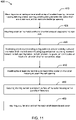
FIG. 11 is a flow diagram of anexample method 400 for assembling thelawnmower 100 including thebelt cover 220. Themethod 400 may be performed by a technician or assembly robot. - At
block 410, themethod 400 includes mounting a motor having a motor shaft on top of a cutter housing, the cutter housing defining a lower opening, a belt opening between the motor shaft and a rear axle, and at least one discharge opening. In an aspect, for example, the technician or assembly robot may mount themotor 110 having themotor shaft 210 on top of thecutter housing 120. Thecutter housing 120 defines alower opening 126, belt opening 310 between themotor shaft 210 and arear axle 252, and at least onedischarge chute 340. - At
block 420, themethod 400 includes mounting a belt on the motor shaft and on a transmission coupled to the rear axle. In an aspect, for example the technician or assembly robot may mount thebelt 240 on themotor shaft 210 and on thetransmission 250, which is coupled to therear axle 252 or at least onerear wheel 124. - At
block 430, themethod 400 includes positioning a belt cover including a ring portion to at least partially surround the motor shaft, the belt cover including a guard portion extending rearward toward the belt opening below the belt, wherein the guard portion includes at least one tab extending from a rearward edge. In an aspect, for example, the technician or assembly robot may position thebelt cover 220 including aring portion 320 to at least partially surround themotor shaft 210. Thebelt cover 220 includes aguard portion 330 extending rearward toward thebelt opening 310 below thebelt 240. Theguard portion 330 includes at least onetab 360 extending from a rearward edge. - At
block 440, themethod 400 includes inserting the at least one tab into a corresponding pocket on the cutter housing adjacent the belt opening. In an aspect, for example, the technician or assembly robot may insert the at least onetab 360 into acorresponding pocket 314 on thecutter housing 120 adjacent thebelt opening 310. In an aspect, thecutter housing 120 includes arear assembly 300 defining thebelt opening 310 and the corresponding pockets 314. - In
block 450, themethod 400 includes securing the ring portion to a bottom surface of the cutter housing with a plurality of fasteners. In an aspect, for example, the technician or assembly robot may secure thering portion 320 to the bottom surface of thecutter housing 120 with a plurality of fasteners. - In
block 460, themethod 400 may include mounting a cutter at an end of the motor shaft below the belt cover. In an aspect, for example, the technician or assembly robot may mount thecutter 212 at the end of themotor shaft 210 below thebelt cover 220.
Claims (15)
- A lawnmower (100), comprising:a cutter (212) mounted to a shaft (210) oriented in a vertical direction;a rear axle (252) oriented in a horizontal direction;a cutter housing (120) defining a lower opening (126) below the cutter, a belt opening (310) between the shaft and the rear axle, and at least one discharge opening (340);the lawnmower being characterized in that it further comprises a belt cover (220) including a ring portion (320) at least partially surrounding the shaft above the cutter and a guard portion (330) extending toward the belt opening, wherein the belt cover includes at least one tab (360) that engages a corresponding pocket (314) on the cutter housing adjacent the belt opening.
- The lawnmower of claim 1, wherein the engagement between the at least one tab and the corresponding pocket constrains the belt cover in a vertical direction and a horizontal direction.
- The lawnmower of claim 1, further comprising a belt (240) located between the belt cover and the cutter housing, wherein the belt is mounted to the shaft and to a transmission (250) operable to drive the rear axle or a wheel (124) mounted thereto.
- The lawnmower of claim 1, wherein the ring portion of the belt cover is mounted to the cutter housing via at least one fastener.
- The lawnmower of claim 1, wherein the cutter housing comprises:a semi-annular top cover extending above and around the cutter to define the lower opening and a rear opening; anda rear assembly (300) positioned within the rear opening and defining the belt opening and the at least one discharge opening.
- The lawnmower of claim 5, wherein the rear assembly further defines a rear axle support that retains the rear axle.
- The lawnmower of claim 5, wherein the rear assembly includes a common vertical wall (308) separating the belt opening and at least one discharge opening, and
wherein, preferably, the guard portion includes a vertical wall (334) that contacts the common vertical wall of the rear assembly. - The lawnmower of claim 5, wherein the corresponding pocket extends upward from a lower surface of the belt opening.
- The lawnmower of claim 1, wherein the at least one tab includes at least three tabs spaced along an edge of the guard portion.
- The lawnmower of claim 1,
wherein the guard portion extends rearward toward the belt opening in a rear wall of a cutter housing, wherein the belt cover includes at least one tab extending rearward that engages a corresponding pocket on the rear wall of the cutter housing. - The lawnmower of claim 10,wherein the ring portion includes a plurality of mounting holes (322) in a top surface of the ring portion, the mounting holes aligning with openings (324) in the cutter housing.
- The lawnmower of claim 10,wherein the guard portion includesa vertical wall portion (334)along a leading edge in a direction of movement of the cutter, and/ora bottom surface (332) that slopes upwards toward a trailing edge that contacts a bottom surface of the cutter housing.
- The lawnmower of claim 10,wherein the at least one tabincludes three tabs, and/orforms an interference fit with the corresponding pocket.
- A method of assembling a lawnmower, comprising:mounting a motor having a motor shaft on top of a cutter housing, the cutter housing defining a lower opening, a belt opening between the motor shaft and a rear axle, and at least one discharge opening (410);mounting a belt on the motor shaft and on a transmission coupled to the rear axle (420);positioning a belt cover including a ring portion at least partially surrounding the motor shaft, the belt cover including a guard portion extending rearward toward the belt opening below the belt, wherein the guard portion includes at least one tab extending from a rearward edge (430);inserting the at least one tab into a corresponding pocket on the cutter housing adjacent the belt opening (440); andsecuring the ring portion to a bottom surface of the cutter housing with a plurality of fasteners (450).
- The method of claim 14, wherein the cutter housing comprises a dome-shaped top cover extending above and around the cutter to define the lower opening and a rear opening, and a rear assembly positioned within the rear opening and defining the belt opening and the at least one discharge opening, the method further comprising mounting the rear assembly to the domed top cover, securing the ring portion to a bottom surface of the cutter housing, preferably, comprising securing the ring portion to the domed top cover, and/or
wherein said method further comprises mounting a cutter at an end of the motor shaft below the belt cover (460).
Applications Claiming Priority (1)
| Application Number | Priority Date | Filing Date | Title |
|---|---|---|---|
| US16/050,965 US10765061B2 (en) | 2018-07-31 | 2018-07-31 | Cover attachment for lawnmower cutter housing |
Publications (2)
| Publication Number | Publication Date |
|---|---|
| EP3603373A1 EP3603373A1 (en) | 2020-02-05 |
| EP3603373B1 true EP3603373B1 (en) | 2022-08-10 |
Family
ID=66826921
Family Applications (1)
| Application Number | Title | Priority Date | Filing Date |
|---|---|---|---|
| EP19179685.3A Active EP3603373B1 (en) | 2018-07-31 | 2019-06-12 | Cover attachment for lawnmower cutter housing |
Country Status (3)
| Country | Link |
|---|---|
| US (1) | US10765061B2 (en) |
| EP (1) | EP3603373B1 (en) |
| CN (1) | CN110771338B (en) |
Families Citing this family (1)
| Publication number | Priority date | Publication date | Assignee | Title |
|---|---|---|---|---|
| US11470777B2 (en) * | 2018-08-01 | 2022-10-18 | Honda Motor Co., Ltd. | Variable mulching assembly for use with a lawnmower |
Family Cites Families (11)
| Publication number | Priority date | Publication date | Assignee | Title |
|---|---|---|---|---|
| US3646739A (en) | 1969-11-21 | 1972-03-07 | Outboard Marine Corp | Safety lawn mower |
| JP3433069B2 (en) | 1997-01-14 | 2003-08-04 | 本田技研工業株式会社 | Electric lawn mower |
| US5957796A (en) * | 1998-03-19 | 1999-09-28 | Mclean; Vernon | Belt guard |
| TWM278226U (en) | 2001-08-22 | 2005-10-21 | Honda Motor Co Ltd | Electric lawn mower |
| TWI248783B (en) | 2001-08-22 | 2006-02-11 | Honda Motor Co Ltd | Electric lawn mower |
| US20030182919A1 (en) | 2002-03-28 | 2003-10-02 | Baumann James R. | Deck assembly for a self-propelled, walk-behind rotary lawn mower |
| US7735305B1 (en) | 2009-03-30 | 2010-06-15 | Exmark Manufacturing Company, Incorporated | Removable cover and implement incorporating same |
| DE202012102156U1 (en) | 2012-06-12 | 2013-09-18 | Al-Ko Kober Ag | mowing machine |
| US8763355B2 (en) * | 2012-10-22 | 2014-07-01 | Kubota Corporation | Mower unit utilizing removably attachamble pulley cover |
| US9699966B2 (en) * | 2014-10-24 | 2017-07-11 | Deere & Company | Mower deck spindle cover |
| CN205865178U (en) | 2016-05-06 | 2017-01-11 | 浙江亚特电器有限公司 | Protection casing quick change mechanism |
-
2018
- 2018-07-31 US US16/050,965 patent/US10765061B2/en active Active
-
2019
- 2019-06-12 EP EP19179685.3A patent/EP3603373B1/en active Active
- 2019-07-03 CN CN201910594029.XA patent/CN110771338B/en not_active Expired - Fee Related
Also Published As
| Publication number | Publication date |
|---|---|
| CN110771338A (en) | 2020-02-11 |
| CN110771338B (en) | 2023-05-26 |
| EP3603373A1 (en) | 2020-02-05 |
| US20200037501A1 (en) | 2020-02-06 |
| US10765061B2 (en) | 2020-09-08 |
Similar Documents
| Publication | Publication Date | Title |
|---|---|---|
| US20030182919A1 (en) | Deck assembly for a self-propelled, walk-behind rotary lawn mower | |
| EP2501215B1 (en) | Improvements to lawnmower safety | |
| US5210998A (en) | Lawn mower with detachable inner members in cutter housing | |
| US6192666B1 (en) | Lawn mower | |
| US4761940A (en) | Rotary mower | |
| US4258539A (en) | Grass discharge chute deflector for rotary lawn mower | |
| EP1527668B1 (en) | Mower Deck and Mowing Machine | |
| EP3549423A1 (en) | Lawn mower robot | |
| EP3295784B1 (en) | Mid-mount riding grass mower | |
| US7360352B2 (en) | Side discharge mower | |
| CA2296661C (en) | Fastener assembly for attachment of composite insert to mower deck | |
| EP3219193A1 (en) | Mower driven by electric motors | |
| US10765061B2 (en) | Cover attachment for lawnmower cutter housing | |
| EP3678468B1 (en) | Multi-configurable mower deck | |
| US4716717A (en) | Power lawn mower | |
| EP3453244A1 (en) | Mower deck discharge chute with drive belt tunnel | |
| US7571593B2 (en) | Bagging lawn mower with selective mulch or discharge options | |
| EP3703484B1 (en) | Drop handle mower | |
| JP4994943B2 (en) | Mowing working machine and mowing machine | |
| US5062258A (en) | Terrain traversing apparatus having means for transferring grass clippings to collection box | |
| US4080774A (en) | Mower | |
| JP2001251924A (en) | Blade mower mower deck | |
| US11470777B2 (en) | Variable mulching assembly for use with a lawnmower | |
| EP3603377B1 (en) | Lawnmower with a variable mulching assembly | |
| EP3812191B1 (en) | Work machine |
Legal Events
| Date | Code | Title | Description |
|---|---|---|---|
| PUAI | Public reference made under article 153(3) epc to a published international application that has entered the european phase |
Free format text: ORIGINAL CODE: 0009012 |
|
| STAA | Information on the status of an ep patent application or granted ep patent |
Free format text: STATUS: THE APPLICATION HAS BEEN PUBLISHED |
|
| AK | Designated contracting states |
Kind code of ref document: A1 Designated state(s): AL AT BE BG CH CY CZ DE DK EE ES FI FR GB GR HR HU IE IS IT LI LT LU LV MC MK MT NL NO PL PT RO RS SE SI SK SM TR |
|
| AX | Request for extension of the european patent |
Extension state: BA ME |
|
| STAA | Information on the status of an ep patent application or granted ep patent |
Free format text: STATUS: REQUEST FOR EXAMINATION WAS MADE |
|
| 17P | Request for examination filed |
Effective date: 20200728 |
|
| RBV | Designated contracting states (corrected) |
Designated state(s): AL AT BE BG CH CY CZ DE DK EE ES FI FR GB GR HR HU IE IS IT LI LT LU LV MC MK MT NL NO PL PT RO RS SE SI SK SM TR |
|
| STAA | Information on the status of an ep patent application or granted ep patent |
Free format text: STATUS: EXAMINATION IS IN PROGRESS |
|
| 17Q | First examination report despatched |
Effective date: 20210324 |
|
| GRAP | Despatch of communication of intention to grant a patent |
Free format text: ORIGINAL CODE: EPIDOSNIGR1 |
|
| STAA | Information on the status of an ep patent application or granted ep patent |
Free format text: STATUS: GRANT OF PATENT IS INTENDED |
|
| INTG | Intention to grant announced |
Effective date: 20220223 |
|
| GRAS | Grant fee paid |
Free format text: ORIGINAL CODE: EPIDOSNIGR3 |
|
| GRAA | (expected) grant |
Free format text: ORIGINAL CODE: 0009210 |
|
| STAA | Information on the status of an ep patent application or granted ep patent |
Free format text: STATUS: THE PATENT HAS BEEN GRANTED |
|
| AK | Designated contracting states |
Kind code of ref document: B1 Designated state(s): AL AT BE BG CH CY CZ DE DK EE ES FI FR GB GR HR HU IE IS IT LI LT LU LV MC MK MT NL NO PL PT RO RS SE SI SK SM TR |
|
| REG | Reference to a national code |
Ref country code: AT Ref legal event code: REF Ref document number: 1509821 Country of ref document: AT Kind code of ref document: T Effective date: 20220815 Ref country code: CH Ref legal event code: EP |
|
| REG | Reference to a national code |
Ref country code: IE Ref legal event code: FG4D |
|
| REG | Reference to a national code |
Ref country code: DE Ref legal event code: R096 Ref document number: 602019017987 Country of ref document: DE |
|
| REG | Reference to a national code |
Ref country code: NL Ref legal event code: MP Effective date: 20220810 |
|
| REG | Reference to a national code |
Ref country code: LT Ref legal event code: MG9D |
|
| PG25 | Lapsed in a contracting state [announced via postgrant information from national office to epo] |
Ref country code: SE Free format text: LAPSE BECAUSE OF FAILURE TO SUBMIT A TRANSLATION OF THE DESCRIPTION OR TO PAY THE FEE WITHIN THE PRESCRIBED TIME-LIMIT Effective date: 20220810 Ref country code: RS Free format text: LAPSE BECAUSE OF FAILURE TO SUBMIT A TRANSLATION OF THE DESCRIPTION OR TO PAY THE FEE WITHIN THE PRESCRIBED TIME-LIMIT Effective date: 20220810 Ref country code: PT Free format text: LAPSE BECAUSE OF FAILURE TO SUBMIT A TRANSLATION OF THE DESCRIPTION OR TO PAY THE FEE WITHIN THE PRESCRIBED TIME-LIMIT Effective date: 20221212 Ref country code: NO Free format text: LAPSE BECAUSE OF FAILURE TO SUBMIT A TRANSLATION OF THE DESCRIPTION OR TO PAY THE FEE WITHIN THE PRESCRIBED TIME-LIMIT Effective date: 20221110 Ref country code: NL Free format text: LAPSE BECAUSE OF FAILURE TO SUBMIT A TRANSLATION OF THE DESCRIPTION OR TO PAY THE FEE WITHIN THE PRESCRIBED TIME-LIMIT Effective date: 20220810 Ref country code: LV Free format text: LAPSE BECAUSE OF FAILURE TO SUBMIT A TRANSLATION OF THE DESCRIPTION OR TO PAY THE FEE WITHIN THE PRESCRIBED TIME-LIMIT Effective date: 20220810 Ref country code: LT Free format text: LAPSE BECAUSE OF FAILURE TO SUBMIT A TRANSLATION OF THE DESCRIPTION OR TO PAY THE FEE WITHIN THE PRESCRIBED TIME-LIMIT Effective date: 20220810 Ref country code: FI Free format text: LAPSE BECAUSE OF FAILURE TO SUBMIT A TRANSLATION OF THE DESCRIPTION OR TO PAY THE FEE WITHIN THE PRESCRIBED TIME-LIMIT Effective date: 20220810 |
|
| REG | Reference to a national code |
Ref country code: AT Ref legal event code: MK05 Ref document number: 1509821 Country of ref document: AT Kind code of ref document: T Effective date: 20220810 |
|
| PG25 | Lapsed in a contracting state [announced via postgrant information from national office to epo] |
Ref country code: PL Free format text: LAPSE BECAUSE OF FAILURE TO SUBMIT A TRANSLATION OF THE DESCRIPTION OR TO PAY THE FEE WITHIN THE PRESCRIBED TIME-LIMIT Effective date: 20220810 Ref country code: IS Free format text: LAPSE BECAUSE OF FAILURE TO SUBMIT A TRANSLATION OF THE DESCRIPTION OR TO PAY THE FEE WITHIN THE PRESCRIBED TIME-LIMIT Effective date: 20221210 Ref country code: HR Free format text: LAPSE BECAUSE OF FAILURE TO SUBMIT A TRANSLATION OF THE DESCRIPTION OR TO PAY THE FEE WITHIN THE PRESCRIBED TIME-LIMIT Effective date: 20220810 Ref country code: GR Free format text: LAPSE BECAUSE OF FAILURE TO SUBMIT A TRANSLATION OF THE DESCRIPTION OR TO PAY THE FEE WITHIN THE PRESCRIBED TIME-LIMIT Effective date: 20221111 |
|
| PG25 | Lapsed in a contracting state [announced via postgrant information from national office to epo] |
Ref country code: SM Free format text: LAPSE BECAUSE OF FAILURE TO SUBMIT A TRANSLATION OF THE DESCRIPTION OR TO PAY THE FEE WITHIN THE PRESCRIBED TIME-LIMIT Effective date: 20220810 Ref country code: RO Free format text: LAPSE BECAUSE OF FAILURE TO SUBMIT A TRANSLATION OF THE DESCRIPTION OR TO PAY THE FEE WITHIN THE PRESCRIBED TIME-LIMIT Effective date: 20220810 Ref country code: ES Free format text: LAPSE BECAUSE OF FAILURE TO SUBMIT A TRANSLATION OF THE DESCRIPTION OR TO PAY THE FEE WITHIN THE PRESCRIBED TIME-LIMIT Effective date: 20220810 Ref country code: DK Free format text: LAPSE BECAUSE OF FAILURE TO SUBMIT A TRANSLATION OF THE DESCRIPTION OR TO PAY THE FEE WITHIN THE PRESCRIBED TIME-LIMIT Effective date: 20220810 Ref country code: CZ Free format text: LAPSE BECAUSE OF FAILURE TO SUBMIT A TRANSLATION OF THE DESCRIPTION OR TO PAY THE FEE WITHIN THE PRESCRIBED TIME-LIMIT Effective date: 20220810 Ref country code: AT Free format text: LAPSE BECAUSE OF FAILURE TO SUBMIT A TRANSLATION OF THE DESCRIPTION OR TO PAY THE FEE WITHIN THE PRESCRIBED TIME-LIMIT Effective date: 20220810 |
|
| REG | Reference to a national code |
Ref country code: DE Ref legal event code: R097 Ref document number: 602019017987 Country of ref document: DE |
|
| PG25 | Lapsed in a contracting state [announced via postgrant information from national office to epo] |
Ref country code: SK Free format text: LAPSE BECAUSE OF FAILURE TO SUBMIT A TRANSLATION OF THE DESCRIPTION OR TO PAY THE FEE WITHIN THE PRESCRIBED TIME-LIMIT Effective date: 20220810 Ref country code: EE Free format text: LAPSE BECAUSE OF FAILURE TO SUBMIT A TRANSLATION OF THE DESCRIPTION OR TO PAY THE FEE WITHIN THE PRESCRIBED TIME-LIMIT Effective date: 20220810 |
|
| PLBE | No opposition filed within time limit |
Free format text: ORIGINAL CODE: 0009261 |
|
| STAA | Information on the status of an ep patent application or granted ep patent |
Free format text: STATUS: NO OPPOSITION FILED WITHIN TIME LIMIT |
|
| PG25 | Lapsed in a contracting state [announced via postgrant information from national office to epo] |
Ref country code: AL Free format text: LAPSE BECAUSE OF FAILURE TO SUBMIT A TRANSLATION OF THE DESCRIPTION OR TO PAY THE FEE WITHIN THE PRESCRIBED TIME-LIMIT Effective date: 20220810 |
|
| 26N | No opposition filed |
Effective date: 20230511 |
|
| PGFP | Annual fee paid to national office [announced via postgrant information from national office to epo] |
Ref country code: DE Payment date: 20230418 Year of fee payment: 5 |
|
| PG25 | Lapsed in a contracting state [announced via postgrant information from national office to epo] |
Ref country code: SI Free format text: LAPSE BECAUSE OF FAILURE TO SUBMIT A TRANSLATION OF THE DESCRIPTION OR TO PAY THE FEE WITHIN THE PRESCRIBED TIME-LIMIT Effective date: 20220810 |
|
| PG25 | Lapsed in a contracting state [announced via postgrant information from national office to epo] |
Ref country code: MC Free format text: LAPSE BECAUSE OF FAILURE TO SUBMIT A TRANSLATION OF THE DESCRIPTION OR TO PAY THE FEE WITHIN THE PRESCRIBED TIME-LIMIT Effective date: 20220810 |
|
| PG25 | Lapsed in a contracting state [announced via postgrant information from national office to epo] |
Ref country code: MC Free format text: LAPSE BECAUSE OF FAILURE TO SUBMIT A TRANSLATION OF THE DESCRIPTION OR TO PAY THE FEE WITHIN THE PRESCRIBED TIME-LIMIT Effective date: 20220810 |
|
| REG | Reference to a national code |
Ref country code: CH Ref legal event code: PL |
|
| REG | Reference to a national code |
Ref country code: BE Ref legal event code: MM Effective date: 20230630 |
|
| GBPC | Gb: european patent ceased through non-payment of renewal fee |
Effective date: 20230612 |
|
| PG25 | Lapsed in a contracting state [announced via postgrant information from national office to epo] |
Ref country code: LU Free format text: LAPSE BECAUSE OF NON-PAYMENT OF DUE FEES Effective date: 20230612 |
|
| REG | Reference to a national code |
Ref country code: IE Ref legal event code: MM4A |
|
| PG25 | Lapsed in a contracting state [announced via postgrant information from national office to epo] |
Ref country code: LU Free format text: LAPSE BECAUSE OF NON-PAYMENT OF DUE FEES Effective date: 20230612 |
|
| PG25 | Lapsed in a contracting state [announced via postgrant information from national office to epo] |
Ref country code: IE Free format text: LAPSE BECAUSE OF NON-PAYMENT OF DUE FEES Effective date: 20230612 |
|
| PG25 | Lapsed in a contracting state [announced via postgrant information from national office to epo] |
Ref country code: IE Free format text: LAPSE BECAUSE OF NON-PAYMENT OF DUE FEES Effective date: 20230612 Ref country code: GB Free format text: LAPSE BECAUSE OF NON-PAYMENT OF DUE FEES Effective date: 20230612 Ref country code: CH Free format text: LAPSE BECAUSE OF NON-PAYMENT OF DUE FEES Effective date: 20230630 |
|
| PG25 | Lapsed in a contracting state [announced via postgrant information from national office to epo] |
Ref country code: IT Free format text: LAPSE BECAUSE OF FAILURE TO SUBMIT A TRANSLATION OF THE DESCRIPTION OR TO PAY THE FEE WITHIN THE PRESCRIBED TIME-LIMIT Effective date: 20220810 Ref country code: FR Free format text: LAPSE BECAUSE OF NON-PAYMENT OF DUE FEES Effective date: 20230630 Ref country code: BE Free format text: LAPSE BECAUSE OF NON-PAYMENT OF DUE FEES Effective date: 20230630 |
|
| PG25 | Lapsed in a contracting state [announced via postgrant information from national office to epo] |
Ref country code: BG Free format text: LAPSE BECAUSE OF FAILURE TO SUBMIT A TRANSLATION OF THE DESCRIPTION OR TO PAY THE FEE WITHIN THE PRESCRIBED TIME-LIMIT Effective date: 20220810 |
|
| PG25 | Lapsed in a contracting state [announced via postgrant information from national office to epo] |
Ref country code: BG Free format text: LAPSE BECAUSE OF FAILURE TO SUBMIT A TRANSLATION OF THE DESCRIPTION OR TO PAY THE FEE WITHIN THE PRESCRIBED TIME-LIMIT Effective date: 20220810 |
|
| REG | Reference to a national code |
Ref country code: DE Ref legal event code: R119 Ref document number: 602019017987 Country of ref document: DE |
|
| PG25 | Lapsed in a contracting state [announced via postgrant information from national office to epo] |
Ref country code: DE Free format text: LAPSE BECAUSE OF NON-PAYMENT OF DUE FEES Effective date: 20250101 |
|
| PG25 | Lapsed in a contracting state [announced via postgrant information from national office to epo] |
Ref country code: CY Free format text: LAPSE BECAUSE OF FAILURE TO SUBMIT A TRANSLATION OF THE DESCRIPTION OR TO PAY THE FEE WITHIN THE PRESCRIBED TIME-LIMIT; INVALID AB INITIO Effective date: 20190612 |
|
| PG25 | Lapsed in a contracting state [announced via postgrant information from national office to epo] |
Ref country code: HU Free format text: LAPSE BECAUSE OF FAILURE TO SUBMIT A TRANSLATION OF THE DESCRIPTION OR TO PAY THE FEE WITHIN THE PRESCRIBED TIME-LIMIT; INVALID AB INITIO Effective date: 20190612 |
|
| PG25 | Lapsed in a contracting state [announced via postgrant information from national office to epo] |
Ref country code: TR Free format text: LAPSE BECAUSE OF FAILURE TO SUBMIT A TRANSLATION OF THE DESCRIPTION OR TO PAY THE FEE WITHIN THE PRESCRIBED TIME-LIMIT Effective date: 20220810 |