EP3602142B1 - Vibration damping of an ancillary device attached to a marine streamer and method - Google Patents
Vibration damping of an ancillary device attached to a marine streamer and method Download PDFInfo
- Publication number
- EP3602142B1 EP3602142B1 EP18777012.8A EP18777012A EP3602142B1 EP 3602142 B1 EP3602142 B1 EP 3602142B1 EP 18777012 A EP18777012 A EP 18777012A EP 3602142 B1 EP3602142 B1 EP 3602142B1
- Authority
- EP
- European Patent Office
- Prior art keywords
- collar
- streamer
- clamp
- vibration
- strut
- Prior art date
- Legal status (The legal status is an assumption and is not a legal conclusion. Google has not performed a legal analysis and makes no representation as to the accuracy of the status listed.)
- Active
Links
Images






Classifications
-
- G—PHYSICS
- G01—MEASURING; TESTING
- G01D—MEASURING NOT SPECIALLY ADAPTED FOR A SPECIFIC VARIABLE; ARRANGEMENTS FOR MEASURING TWO OR MORE VARIABLES NOT COVERED IN A SINGLE OTHER SUBCLASS; TARIFF METERING APPARATUS; MEASURING OR TESTING NOT OTHERWISE PROVIDED FOR
- G01D11/00—Component parts of measuring arrangements not specially adapted for a specific variable
- G01D11/10—Elements for damping the movement of parts
-
- G—PHYSICS
- G01—MEASURING; TESTING
- G01V—GEOPHYSICS; GRAVITATIONAL MEASUREMENTS; DETECTING MASSES OR OBJECTS; TAGS
- G01V1/00—Seismology; Seismic or acoustic prospecting or detecting
- G01V1/16—Receiving elements for seismic signals; Arrangements or adaptations of receiving elements
- G01V1/20—Arrangements of receiving elements, e.g. geophone pattern
- G01V1/201—Constructional details of seismic cables, e.g. streamers
-
- F—MECHANICAL ENGINEERING; LIGHTING; HEATING; WEAPONS; BLASTING
- F16—ENGINEERING ELEMENTS AND UNITS; GENERAL MEASURES FOR PRODUCING AND MAINTAINING EFFECTIVE FUNCTIONING OF MACHINES OR INSTALLATIONS; THERMAL INSULATION IN GENERAL
- F16F—SPRINGS; SHOCK-ABSORBERS; MEANS FOR DAMPING VIBRATION
- F16F15/00—Suppression of vibrations in systems; Means or arrangements for avoiding or reducing out-of-balance forces, e.g. due to motion
- F16F15/02—Suppression of vibrations of non-rotating, e.g. reciprocating systems; Suppression of vibrations of rotating systems by use of members not moving with the rotating systems
- F16F15/04—Suppression of vibrations of non-rotating, e.g. reciprocating systems; Suppression of vibrations of rotating systems by use of members not moving with the rotating systems using elastic means
- F16F15/08—Suppression of vibrations of non-rotating, e.g. reciprocating systems; Suppression of vibrations of rotating systems by use of members not moving with the rotating systems using elastic means with rubber springs ; with springs made of rubber and metal
-
- F—MECHANICAL ENGINEERING; LIGHTING; HEATING; WEAPONS; BLASTING
- F16—ENGINEERING ELEMENTS AND UNITS; GENERAL MEASURES FOR PRODUCING AND MAINTAINING EFFECTIVE FUNCTIONING OF MACHINES OR INSTALLATIONS; THERMAL INSULATION IN GENERAL
- F16F—SPRINGS; SHOCK-ABSORBERS; MEANS FOR DAMPING VIBRATION
- F16F3/00—Spring units consisting of several springs, e.g. for obtaining a desired spring characteristic
- F16F3/08—Spring units consisting of several springs, e.g. for obtaining a desired spring characteristic with springs made of a material having high internal friction, e.g. rubber
- F16F3/087—Units comprising several springs made of plastics or the like material
- F16F3/0873—Units comprising several springs made of plastics or the like material of the same material or the material not being specified
- F16F3/0876—Units comprising several springs made of plastics or the like material of the same material or the material not being specified and of the same shape
-
- F—MECHANICAL ENGINEERING; LIGHTING; HEATING; WEAPONS; BLASTING
- F16—ENGINEERING ELEMENTS AND UNITS; GENERAL MEASURES FOR PRODUCING AND MAINTAINING EFFECTIVE FUNCTIONING OF MACHINES OR INSTALLATIONS; THERMAL INSULATION IN GENERAL
- F16F—SPRINGS; SHOCK-ABSORBERS; MEANS FOR DAMPING VIBRATION
- F16F3/00—Spring units consisting of several springs, e.g. for obtaining a desired spring characteristic
- F16F3/08—Spring units consisting of several springs, e.g. for obtaining a desired spring characteristic with springs made of a material having high internal friction, e.g. rubber
- F16F3/087—Units comprising several springs made of plastics or the like material
- F16F3/093—Units comprising several springs made of plastics or the like material the springs being of different materials, e.g. having different types of rubber
-
- G—PHYSICS
- G01—MEASURING; TESTING
- G01V—GEOPHYSICS; GRAVITATIONAL MEASUREMENTS; DETECTING MASSES OR OBJECTS; TAGS
- G01V1/00—Seismology; Seismic or acoustic prospecting or detecting
- G01V1/38—Seismology; Seismic or acoustic prospecting or detecting specially adapted for water-covered areas
- G01V1/3817—Positioning of seismic devices
-
- G—PHYSICS
- G01—MEASURING; TESTING
- G01V—GEOPHYSICS; GRAVITATIONAL MEASUREMENTS; DETECTING MASSES OR OBJECTS; TAGS
- G01V1/00—Seismology; Seismic or acoustic prospecting or detecting
- G01V1/38—Seismology; Seismic or acoustic prospecting or detecting specially adapted for water-covered areas
- G01V1/3817—Positioning of seismic devices
- G01V1/3826—Positioning of seismic devices dynamic steering, e.g. by paravanes or birds
-
- G—PHYSICS
- G01—MEASURING; TESTING
- G01V—GEOPHYSICS; GRAVITATIONAL MEASUREMENTS; DETECTING MASSES OR OBJECTS; TAGS
- G01V1/00—Seismology; Seismic or acoustic prospecting or detecting
- G01V1/38—Seismology; Seismic or acoustic prospecting or detecting specially adapted for water-covered areas
- G01V1/3843—Deployment of seismic devices, e.g. of streamers
-
- F—MECHANICAL ENGINEERING; LIGHTING; HEATING; WEAPONS; BLASTING
- F16—ENGINEERING ELEMENTS AND UNITS; GENERAL MEASURES FOR PRODUCING AND MAINTAINING EFFECTIVE FUNCTIONING OF MACHINES OR INSTALLATIONS; THERMAL INSULATION IN GENERAL
- F16F—SPRINGS; SHOCK-ABSORBERS; MEANS FOR DAMPING VIBRATION
- F16F1/00—Springs
- F16F1/36—Springs made of rubber or other material having high internal friction, e.g. thermoplastic elastomers
- F16F1/373—Springs made of rubber or other material having high internal friction, e.g. thermoplastic elastomers characterised by having a particular shape
- F16F1/376—Springs made of rubber or other material having high internal friction, e.g. thermoplastic elastomers characterised by having a particular shape having projections, studs, serrations or the like on at least one surface
-
- F—MECHANICAL ENGINEERING; LIGHTING; HEATING; WEAPONS; BLASTING
- F16—ENGINEERING ELEMENTS AND UNITS; GENERAL MEASURES FOR PRODUCING AND MAINTAINING EFFECTIVE FUNCTIONING OF MACHINES OR INSTALLATIONS; THERMAL INSULATION IN GENERAL
- F16F—SPRINGS; SHOCK-ABSORBERS; MEANS FOR DAMPING VIBRATION
- F16F2224/00—Materials; Material properties
- F16F2224/02—Materials; Material properties solids
- F16F2224/025—Elastomers
-
- F—MECHANICAL ENGINEERING; LIGHTING; HEATING; WEAPONS; BLASTING
- F16—ENGINEERING ELEMENTS AND UNITS; GENERAL MEASURES FOR PRODUCING AND MAINTAINING EFFECTIVE FUNCTIONING OF MACHINES OR INSTALLATIONS; THERMAL INSULATION IN GENERAL
- F16F—SPRINGS; SHOCK-ABSORBERS; MEANS FOR DAMPING VIBRATION
- F16F2226/00—Manufacturing; Treatments
- F16F2226/04—Assembly or fixing methods; methods to form or fashion parts
Definitions
- Embodiments of the subject matter disclosed herein generally relate to methods and devices for vibration mitigation, and more specifically, to a collar system that attaches an ancillary device to a marine streamer and reduces noise generated by the ancillary device.
- a marine streamer typically includes sensor components, data-transmission cables, power-transmission cables and strength enhancing and buoyancy enhancing components arranged in a single cable.
- the marine streamer is used for gathering data on the nature and composition of the earth below a body of water using seismic imaging techniques.
- the marine streamer may be designed to reduce hydrodynamic induced flow noise.
- the marine seismic cable may be cylindrical.
- FIG. 1 depicts a traditional marine seismic data acquisition system.
- a vessel 101 including a lead-in towing assembly 102, may deploy and tow streamers 103, on or below the surface of the water.
- the streamers 103 may be of any suitable length, and may be made up of shorter connected sections 106 of electro-mechanical cabling which may also be of any suitable length.
- a streamer 103 may be kilometers in length, with each section 106 being, for example, 75 meters to 200 meters in length. Sections 106 may be detachable from each other.
- Seismic data acquisition systems may make use of more than one streamer 103.
- the streamer 103 may be deployed as a single section 106, a linear series of sections 106, or as a horizontal offset series of sections 106, producing a streamer spread.
- the streamers may be deployed to be horizontal, slanted, or curved.
- Sections 106 of the streamer 103 include seismic sensors 104, typically hydrophones, geophones, accelerometers, electro-magnetic sensors, optical sensors, gravity sensors, or a combination thereof and may be distributed at regular intervals along the streamer 103.
- a seismic source 108 may be used to produce a seismic wave, using any suitable manner of generating acoustic energy.
- the seismic source may include one or more air guns or vibratory elements.
- the seismic wave may be reflected by the geologic features of the sea floor and picked up by the sensors 104. Vibrations emanating from the head of the streamer spread 110, near the marine vessel 101, may contaminate the seismic signals measured by the sensors 104.
- Radial vibration isolation modules 109 may be placed between the towing assembly 102 and the streamers 103, at the head of the streamer spread 110, in order to mitigate the transmission of vibration noise. There are several types of radial vibration isolation modules 109 that may be used in the streamers 103 at the head of the streamer spread 110. Each of the available types of radial vibration isolation modules 109 may include a single stretch section with vibration attenuation that occurs due to a complex spring rate of the radial vibration isolation module 109. Radial vibration isolation modules 109 may be tailored to attenuate vibration over the frequency bandwidth of 2 to 250 Hz, which may be common in seismic acquisition.
- the streamers 103 may each include one or more ancillary devices 107, which are externally attached to the streamers. These ancillary devices may be positioning devices, also known as birds or navigation control devices, recovery devices, etc. These ancillary devices are typically clamped to the outsides of the streamers 103.
- the streamers 103 are deployed in a viscous fluid, for example, water, the streamers 103 are subject to energy sources from both man-made sources, such as energy transmitted through the tow assembly 102, or energy from the propulsion system of the marine vessel 101, or energy from the ancillary devices externally attached to the streamer, and natural sources, such as wave motion and weather.
- the energy from these sources may diminish the quality of the seismic data recorded by the sensors 104, as they may interfere with the signal from the acoustic energy reflected off the sea floor.
- the signal measured by the sensors 104 of a streamer 103 may be divided into two parts, the "signal” pertaining to the geophysical structure of the sea floor, and “noise,” which may be picked up from other man-made or natural sources.
- the signal is desired while the noise contaminates the signal.
- the noise introduced by the ancillary devices is more critical. In order to maximize the performance of such streamers, only particle motion resulting from a reflected pressure wave should be seen by the streamers sensors. At-sea testing of the streamers has shown the noise floor of a multi-component streamer to be controlled by vibrations induced by the use (attachment) of ancillary devices. Traditional attachment systems currently on the market (see, for example, U.S. Pat. Nos. 5,709,497 and 6,263,823 ) were not designed to mitigate vibration from either the collar itself or the ancillary device.
- a low-vibration collar (LVC) system for attaching an ancillary device to a cable (e.g., streamer), includes a vibration mitigation system that has at least one of four different vibration mitigation mechanisms.
- the four vibration mitigation mechanisms include: (1) elastic isolation pads, (2) pre-loaded assembly, (3) a suspension system and (4) a spatial filter of rotational motion.
- Figure 2A shows a streamer 201 to which an ancillary device 210 is attached with a traditional clamp and collar system (202 and 220), at a head-end interface 260 and a tail-end interface 262.
- an ancillary device 210 is attached with a traditional clamp and collar system (202 and 220), at a head-end interface 260 and a tail-end interface 262.
- plural overmolds 264 are formed at these interfaces to hold the clamp and collar system 202 and 220 in place.
- the overmolds may be formed directly on the streamer.
- the overmold may include one or more of power transmitting devices and communication devices for exchanging power and/or data with the attached ancillary device.
- an overmold is not necessary for attaching the ancillary devices to the streamer.
- the water velocity 270 generates various forces on the ancillary device 210, which cause the device to move relative to the streamer (the ancillary device rattles relative to the streamer, which is recorded as noise by the accelerometer sensors).
- the two degrees of freedom (vertical motion and rotation or rocking) of the ancillary device relative to the streamer are illustrated by reference number 272.
- a pressure field (waves) 274 resulting from direct and/or reflected seismic waves is also shown. All these factors generate a time series of vibrations 280 that are transmitted to the streamer from the ancillary device via the traditional clamp and collar system. All these vibrations negatively impact the quality of the recorded seismic data.
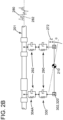
- Figure 2B simultaneously shows the time series of vibrations 280 of the traditional system and the transmitted vibrations 282 for the novel system 302, 320.
- Figure 2B also shows the spring and damper representation 290 of a suspension system 330 and the spring and damper representation 292 of elastic isolation pads 304A-D (herein referred to pads 304).
- FIG. 3A shows an LVC system 300 attached to a streamer 301.
- An ancillary device 310 is shown being attached to the LVC system 300 through a connecting mechanism 309.
- Connecting mechanism 309 may be a hook, a screw, keyhole-shaped dovetail slots, locking cams or any other interface for removably attaching the ancillary device to the external face of the collar.
- FIG. 3B A cross-section along line 3B-3B in Figure 3A is illustrated in Figure 3B .
- This cross-section shows, from inside out, the streamer 301, the elastic isolation pads 304A to 304D being attached to the clamp 302 and riding on the streamer 301, and the suspension system 330 being located between the clamp 302 and the collar 320.
- Figure 3C shows a cross-section along line 3C-3C in Figure 3B.
- Figure 3C shows the elastic isolation pad 304A being sandwiched between the streamer 301 and the clamp 302, and the suspension system 330 being sandwiched between the clamp 302 and the collar 320.
- a vibration mitigation system 325 of the LVC system 300 includes at least one of the following three parts, the elastic isolation pad 304, a gasket 326, and the suspension mechanism 330. Each of these parts are discussed next in more detail.
- the ancillary device 310 may be any traditional device that is attached to a streamer, for example, a navigation control device, recovery device, etc.
- the clamp 302 may be a two-part device having a cylindric shape made out of two halves 302A and 302B (see Figure 4A ) made out of plastic or metal. Other materials may be used.
- An interior 303 of clamp 302 is shown in Figure 4A as having elastic isolation pads 304A to 304D. This is the first vibration mitigation mechanism (1) discussed above. Although the figure shows four pairs of such pads, one skilled in the art would understand that in one application the LVC system has only three pairs of pads or more than four pairs of pads. In still another application, the LVC system has the pads not in pairs.
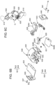
- Figure 4B shows a connecting mechanism 306 (e.g., a screw) that holds the two parts 302A and 302B of the clamp 302 attached to the streamer.
- Figure 4B also shows a groove 303 formed in the body of the clamp 302. As discussed later, this groove may receive a pin from the collar for preventing the collar to translate relative to the clamp along the streamer.
- the elastic isolation pads may be made of low durometer (e.g., 10 to 30 Shore A plastic or polymer material) and these pads negate the hard mounting typical of streamer clamps.
- Figure 3C shows one of the pads 304 being sandwiched between the interior surface of the clamp 302 and the streamer 301.
- the elastic isolation pad 304 is a critically damped pad.
- a critically damped pad is defined as follows. When an oscillation is induced by the ancillary device 310, due to its interaction with the ambient water, the collar 320 moves together with the ancillary device. This motion is traditionally transmitted to the streamer through the clamp 302. However, according to this embodiment, the elastic isolation pad 304 attenuates this movement. If the elastic isolation pad extinguishes this movement after a single oscillation, then the pad is called critically damped. Such a property of the pad can be calculated for any given ancillary device.
- the second vibration mitigation mechanism (2) i.e., the pre-loaded assembly
- the collar 320 is made of two parts 320A and 320B, which are held together by a hinge 322, when the two parts are closed, for example, with a latching device 324, there is a rattle between the two parts of the collar 320.
- This rattle movement is enough to introduce a noise in the frequency spectrum of interest of the recording seismic sensors.
- an elastic gasket 326 which pre-loads the latching collar assembly, is placed between the two parts 320A and 320B, to eliminate the rattle motion.
- the elastic gasket 326 may be glued to one part of the collar. When the collar is closed, due to the pressure exerted by the elastic gasket 326 between the two parts 320A and 320B, no rattling motion appears.
- the elastic gasket may be made of various materials, for example, rubber.
- the third vibration mitigation mechanism (3) i.e., the suspension system 330
- Figure 5A shows a top view of the suspension system 330 having a spring leaf body 532 that is ending with two skis 534 and 536 (see Figure 5B ).
- the body 532 is elastic and can bend as illustrated in Figure 5C.
- Figure 5B shows the body 532 having a base 533, which is fixedly attached to an inside of the collar 320.
- the two sides 532A and 532B of the body 532 act independent of each other as illustrated in Figure 5C , i.e., each side is displaced with a displacement d that is proportional with the force F that acts on the ski.
- the two forces that act on the two skis 534 and 536 may be the same or different.
- Figure 5D shows a side view of the ski 534 and the ski 534 has a bottom side 534A that is flat.
- This flat bottom 534A rides directly on the clamp 302 and acts to spatially filter a chamfer 302C formed in the clamp 302, as illustrated in Figures 5D and 5E .
- Figure 5E shows the ski 534 rotating to easy/smooth a transition from one half 302A of the clamp 302 to the other half 302B, especially when the two halves are not well aligned.
- the middle part of the body 532 can move up and down between the clamp and the collar while the streamer 501 is towed under water.
- the body 532 is located at a height H relative to the surface of the clamp 302. In other words, the body 532 is located higher than the bottom parts of the skis 534 and 536, which ride on the clamp 302. This feature ensures that only the skis contact the clamp.
- the chamfer portion 302C is not uniform, i.e., there is a bump or difference in height of the two parts and this difference produces a jolt in the traditional collar when rotating along the external surface of the clamp.
- the suspension system 330 discussed above is designed to filter out that jolt.
- Figure 5F shows four suspension systems 330 attached to an inside of the collar 320.
- the suspension system 330 may be attached in various ways to the collar 320, for example, with a screw 538.
- Figure 5F also shows the closing mechanism 524 of the collar 320, having a first part 324A and a second part 324B.
- the suspension system 330 has only the skis in contact with clamp 302.
- the collar 320 is capable to move relative to the clamp 302 with at least two degrees of freedom: (i) translate along a vertical axis Z and (ii) rotate by an angle ⁇ relative to a horizontal axis X (that enters into the page) as illustrated in Figure 3C .
- the bottom face 320A of the collar 320 is curved while the top face 320B is flat.
- the curved bottom face 320A allows the collar 320 to rotate by angle ⁇ relative to axis X.
- Angle ⁇ may be between 3 and 30 degrees.
- the suspension system discussed above eliminates the traditional loose fit of the collar and clamp, which is common in devices of this type as the ancillary devices are required to rotate freely about the streamer's longitudinal axis X. As the ancillary device moves through the water it has two degrees of freedom (transverse and pitching) that can produce an impulse input (vibration) to the clamp and thus to the streamer.
- the suspension system discussed above eliminates the impulsive input under normal operating conditions of the ancillary device.
- the suspension system may be fabricated from a low-friction material to minimize the torque required for rotation about the longitudinal axis Y.
- LVC system 600 is attached to a streamer 601 as in the previous embodiments, but its collar only partially encircles the streamer as shown in Figure 6A . More specifically, LVC system 600 includes a clamp 602 to which one or more elastic isolation pads 604A are attached to. When the clamp 602 is attached to the streamer, the elastic isolation pads are sandwiched between the streamer and the clamp.
- a collar 620 is attached to the clamp 602 and uses one or more suspension systems 630, which are attached with corresponding screws 638 to the clamp 620.
- Figure 6A shows the clamp 602 to be a full circle while collar 620 has a gap G (i.e., only partially enclosed the clamp).
- the embodiment shown in Figures 6A and 6B has only three such suspension systems. However, more suspension systems may be used.
- the suspension system 630 may have the same configuration as the one discussed above with regard to Figure 5A to 5F .
- the present collar 620 has an integrated strut system 621 that has a first strut 622 (upper strut) and a second latch strut 624 (lower strut).
- the first strut 622 (see Figure 6B and 6C ) is attached to a top portion of the collar 620 with corresponding screws 623.
- a bracket 626 may be attached to the first strut with corresponding screws 627 as shown in Figure 6C .
- This bracket may be used to attach the ancillary device 610 to the collar 620, as shown in Figure 6B .
- the second latch strut 624 is attached to a bottom portion of the collar 620 with corresponding screws 625.
- the second latch strut 624 is formed from two parts 624A and 624B, which attach to each other.
- a latch pin 628 and a latch button 629 are attached to each other with a screw 631 and these elements are housed by the second latch strut 624.
- a bracket 640 is attached to the second latch strut 624 with a screw 641.
- a tip 628A (see Figures 6B and 6C ) of the latch pin 628 extends through a corresponding hole 628B formed in the collar 620 and presses against a groove 603 (see Figure 6A and groove 303 in Figure 4B ) formed in the clamp 602.
- the latch pin and latch button form a mechanism for attaching the collar 630 to the clamp 602.
- latch pin 628 retrieves inside the second latch strut 624 and the collar 620 can translate relative to the clamp 302 along the X axis. If the latch pin 628 extends into the groove 603, the reciprocal translation of the collar 620 and the clamp 602 is stopped.
- a security tab 633 is located between the two parts 624A and 624B. The security tab 633 does not allow the activation of the latch pin 628.
- the integrated strut system 621 is manufactured so that a center of gravity CMS of the first strut 622 and the second latching strut 624 is below a center of gravity CM of the streamer 601, so that the integrated strut system and the collar 620 are aligned with a vertical axis Y to aid in the orientation of the attached devices 610, as illustrated in Figure 6D .
- the integrated strut system 621 provides improved flow, which reduces turbulence (i.e., less vibration forces acting on the streamer) when the streamer is towed in water, minimizes the biologic growth by improving the flow of water, provides hydrodynamic damping to rotational motion, and increases the radial distance from the streamer's center to the ancillary tool, which may increase the dynamic righting moment of the device.
- the LVC system 600 has a self-contained locking pin, i.e., the locking pin 628 of the second latch strut 624.
- the existing systems require the user to attach a strap and/or insert a secondary screw in order to keep the collar attached to the clamp.
- the locking pin 628 provides this functionality.
- the present LVC system 600 is further different from the existing devices in the sense that it can be installed either from the head or tail of the streamer.
- the gap G in the collar 620 is greater than a diameter Ds of the streamer, but less than a diameter Dc of the clamp 602 (see Figure 6A ).
- the vibration mitigation system 635 in this embodiment includes no gasket because the collar 620 does not have a hinge and latching mechanism. However, the vibration mitigation system 635 includes at least one of the suspension mechanism 630 and the elastic isolation pads 604.
- the method includes a step 700 of attaching a clamp 302/602 to the streamer 301 towed underwater, a step 702 of attaching a collar 320/620 to the clamp 302, a step 704 of attaching the ancillary device to the collar with a connecting mechanism 309 located on the collar, and a step 706 of attenuating an amplitude of a vibration produced by the ancillary device with a vibration mitigation system (325, 525, 635).
- the vibration mitigation system includes plural elastic insulation pads located between the streamer and the clamp and a suspension mechanism located between the clamp and the collar. The vibration interferes with seismic data recorded by seismic sensors located on the streamer and thus, by reducing these vibrations, the clamp and collar system of this application permits the acquisition of more accurate seismic data.
Landscapes
- Life Sciences & Earth Sciences (AREA)
- Physics & Mathematics (AREA)
- Engineering & Computer Science (AREA)
- General Physics & Mathematics (AREA)
- Acoustics & Sound (AREA)
- General Life Sciences & Earth Sciences (AREA)
- Geology (AREA)
- Remote Sensing (AREA)
- Environmental & Geological Engineering (AREA)
- Geophysics (AREA)
- General Engineering & Computer Science (AREA)
- Oceanography (AREA)
- Mechanical Engineering (AREA)
- Chemical & Material Sciences (AREA)
- Combustion & Propulsion (AREA)
- Aviation & Aerospace Engineering (AREA)
- Vibration Prevention Devices (AREA)
Description
- Embodiments of the subject matter disclosed herein generally relate to methods and devices for vibration mitigation, and more specifically, to a collar system that attaches an ancillary device to a marine streamer and reduces noise generated by the ancillary device.
- A marine streamer typically includes sensor components, data-transmission cables, power-transmission cables and strength enhancing and buoyancy enhancing components arranged in a single cable. The marine streamer is used for gathering data on the nature and composition of the earth below a body of water using seismic imaging techniques. The marine streamer may be designed to reduce hydrodynamic induced flow noise. For example, the marine seismic cable may be cylindrical.
-
Figure 1 depicts a traditional marine seismic data acquisition system. Avessel 101, including a lead-intowing assembly 102, may deploy andtow streamers 103, on or below the surface of the water. Thestreamers 103 may be of any suitable length, and may be made up of shorter connectedsections 106 of electro-mechanical cabling which may also be of any suitable length. For example, astreamer 103 may be kilometers in length, with eachsection 106 being, for example, 75 meters to 200 meters in length.Sections 106 may be detachable from each other. Seismic data acquisition systems may make use of more than onestreamer 103. Thestreamer 103 may be deployed as asingle section 106, a linear series ofsections 106, or as a horizontal offset series ofsections 106, producing a streamer spread. The streamers may be deployed to be horizontal, slanted, or curved. -
Sections 106 of thestreamer 103 includeseismic sensors 104, typically hydrophones, geophones, accelerometers, electro-magnetic sensors, optical sensors, gravity sensors, or a combination thereof and may be distributed at regular intervals along thestreamer 103. - A
seismic source 108 may be used to produce a seismic wave, using any suitable manner of generating acoustic energy. The seismic source may include one or more air guns or vibratory elements. When conducting an acoustic survey, the seismic wave may be reflected by the geologic features of the sea floor and picked up by thesensors 104. Vibrations emanating from the head of the streamer spread 110, near themarine vessel 101, may contaminate the seismic signals measured by thesensors 104. - Radial
vibration isolation modules 109 may be placed between thetowing assembly 102 and thestreamers 103, at the head of the streamer spread 110, in order to mitigate the transmission of vibration noise. There are several types of radialvibration isolation modules 109 that may be used in thestreamers 103 at the head of the streamer spread 110. Each of the available types of radialvibration isolation modules 109 may include a single stretch section with vibration attenuation that occurs due to a complex spring rate of the radialvibration isolation module 109. Radialvibration isolation modules 109 may be tailored to attenuate vibration over the frequency bandwidth of 2 to 250 Hz, which may be common in seismic acquisition. - The
streamers 103 may each include one or moreancillary devices 107, which are externally attached to the streamers. These ancillary devices may be positioning devices, also known as birds or navigation control devices, recovery devices, etc. These ancillary devices are typically clamped to the outsides of thestreamers 103. - Because the
streamers 103 are deployed in a viscous fluid, for example, water, thestreamers 103 are subject to energy sources from both man-made sources, such as energy transmitted through thetow assembly 102, or energy from the propulsion system of themarine vessel 101, or energy from the ancillary devices externally attached to the streamer, and natural sources, such as wave motion and weather. The energy from these sources may diminish the quality of the seismic data recorded by thesensors 104, as they may interfere with the signal from the acoustic energy reflected off the sea floor. Thus, the signal measured by thesensors 104 of astreamer 103 may be divided into two parts, the "signal" pertaining to the geophysical structure of the sea floor, and "noise," which may be picked up from other man-made or natural sources. The signal is desired while the noise contaminates the signal. - Existing noise suppression hardware, such as the radial
vibration isolation modules 109, which are concentrated at the head of the streamer spread 110, between thetowing assembly 102 and thestreamers 103, may not provide a sufficient level of noise abatement for the noise introduced by the movement of the ancillary devices in water. - In addition, for multi-component streamers that include sensors that either directly measure the acceleration and/or are susceptible to motion, the noise introduced by the ancillary devices is more critical. In order to maximize the performance of such streamers, only particle motion resulting from a reflected pressure wave should be seen by the streamers sensors. At-sea testing of the streamers has shown the noise floor of a multi-component streamer to be controlled by vibrations induced by the use (attachment) of ancillary devices. Traditional attachment systems currently on the market (see, for example,
U.S. Pat. Nos. 5,709,497 and6,263,823 ) were not designed to mitigate vibration from either the collar itself or the ancillary device. - Thus, there is a need for an apparatus and method for vibration mitigation that overcomes the problems mentioned above.
DocumentsUS 2010/239367 andUS 4 290 124 disclose collar system according to preamble of claim 1. - A novel collar system is provided according to appending claims.
- The accompanying drawings, which are incorporated in and constitute a part of the specification, illustrate one or more embodiments and, together with the description, explain these embodiments. In the drawings:
-
Figure 1 illustrates a marine seismic data acquisition system; -
Figure 2A illustrates the vibration noise introduced by a conventional collar system andFigure 2B illustrates a reduced vibration noise introduced by a low-vibration collar system according to an embodiment of the present invention; -
Figures 3A to 3C illustrate the low-vibration collar system; -
Figures 4A and4B illustrate a clamp and associated pads of the low-vibration collar system; -
Figures 5A to 5F illustrate the suspension mechanism of the low-vibration collar system; -
Figures 6A to 6D illustrate another low-vibration collar system; and -
Figure 7 is a flowchart of a method for attaching an ancillary device to a streamer with a low-vibration collar system. - The following description of the embodiments refers to the accompanying drawings. The same reference numbers in different drawings identify the same or similar elements. The following detailed description does not limit the invention. Instead, the scope of the invention is defined by the appended claims. In various embodiments as illustrated in the figures, a low-vibration collar system is discussed.
- According to an embodiment, a low-vibration collar (LVC) system for attaching an ancillary device to a cable (e.g., streamer), includes a vibration mitigation system that has at least one of four different vibration mitigation mechanisms. The four vibration mitigation mechanisms include: (1) elastic isolation pads, (2) pre-loaded assembly, (3) a suspension system and (4) a spatial filter of rotational motion. These vibration mitigation mechanisms are now discussed in detail.
- One of the problems facing the traditional collar systems is discussed with regard to
Figure 2A and an advantage of the novel LVC system noted above is illustrated inFigure 2B . More specifically,Figure 2A shows astreamer 201 to which anancillary device 210 is attached with a traditional clamp and collar system (202 and 220), at a head-end interface 260 and a tail-end interface 262. Note thatplural overmolds 264 are formed at these interfaces to hold the clamp and collar system 202 and 220 in place. The overmolds may be formed directly on the streamer. The overmold may include one or more of power transmitting devices and communication devices for exchanging power and/or data with the attached ancillary device. However, one skilled in the art would understand that an overmold is not necessary for attaching the ancillary devices to the streamer. - The
water velocity 270 generates various forces on theancillary device 210, which cause the device to move relative to the streamer (the ancillary device rattles relative to the streamer, which is recorded as noise by the accelerometer sensors). The two degrees of freedom (vertical motion and rotation or rocking) of the ancillary device relative to the streamer are illustrated byreference number 272. A pressure field (waves) 274 resulting from direct and/or reflected seismic waves is also shown. All these factors generate a time series ofvibrations 280 that are transmitted to the streamer from the ancillary device via the traditional clamp and collar system. All these vibrations negatively impact the quality of the recorded seismic data. - The amplitude of these vibrations are much reduced when a novel clamp and
collar system 302, 320 (to be discussed with regard toFigures 3A to 3C ) is used, as shown inFigure 2B. Figure 2B simultaneously shows the time series ofvibrations 280 of the traditional system and the transmittedvibrations 282 for thenovel system Figure 2B also shows the spring and damper representation 290 of asuspension system 330 and the spring anddamper representation 292 ofelastic isolation pads 304A-D (herein referred to pads 304). - The novel clamp and
collar system Figures 3A to 3C. Figure 3A shows anLVC system 300 attached to astreamer 301. Anancillary device 310 is shown being attached to theLVC system 300 through a connectingmechanism 309.Connecting mechanism 309 may be a hook, a screw, keyhole-shaped dovetail slots, locking cams or any other interface for removably attaching the ancillary device to the external face of the collar. - A cross-section along
line 3B-3B inFigure 3A is illustrated inFigure 3B . This cross-section shows, from inside out, thestreamer 301, theelastic isolation pads 304A to 304D being attached to theclamp 302 and riding on thestreamer 301, and thesuspension system 330 being located between theclamp 302 and thecollar 320.Figure 3C shows a cross-section alongline 3C-3C inFigure 3B. Figure 3C shows theelastic isolation pad 304A being sandwiched between thestreamer 301 and theclamp 302, and thesuspension system 330 being sandwiched between theclamp 302 and thecollar 320. - A
vibration mitigation system 325 of theLVC system 300 includes at least one of the following three parts, theelastic isolation pad 304, agasket 326, and thesuspension mechanism 330. Each of these parts are discussed next in more detail. - As previously discussed, the
ancillary device 310 may be any traditional device that is attached to a streamer, for example, a navigation control device, recovery device, etc. Theclamp 302 may be a two-part device having a cylindric shape made out of twohalves Figure 4A ) made out of plastic or metal. Other materials may be used. An interior 303 ofclamp 302 is shown inFigure 4A as havingelastic isolation pads 304A to 304D. This is the first vibration mitigation mechanism (1) discussed above. Although the figure shows four pairs of such pads, one skilled in the art would understand that in one application the LVC system has only three pairs of pads or more than four pairs of pads. In still another application, the LVC system has the pads not in pairs. Further,Figure 4B shows a connecting mechanism 306 (e.g., a screw) that holds the twoparts clamp 302 attached to the streamer.Figure 4B also shows agroove 303 formed in the body of theclamp 302. As discussed later, this groove may receive a pin from the collar for preventing the collar to translate relative to the clamp along the streamer. - The elastic isolation pads may be made of low durometer (e.g., 10 to 30 Shore A plastic or polymer material) and these pads negate the hard mounting typical of streamer clamps.
Figure 3C shows one of thepads 304 being sandwiched between the interior surface of theclamp 302 and thestreamer 301. In one embodiment, theelastic isolation pad 304 is a critically damped pad. A critically damped pad is defined as follows. When an oscillation is induced by theancillary device 310, due to its interaction with the ambient water, thecollar 320 moves together with the ancillary device. This motion is traditionally transmitted to the streamer through theclamp 302. However, according to this embodiment, theelastic isolation pad 304 attenuates this movement. If the elastic isolation pad extinguishes this movement after a single oscillation, then the pad is called critically damped. Such a property of the pad can be calculated for any given ancillary device. - The second vibration mitigation mechanism (2), i.e., the pre-loaded assembly, is illustrated in
Figure 3B . According to this mechanism, because thecollar 320 is made of twoparts hinge 322, when the two parts are closed, for example, with alatching device 324, there is a rattle between the two parts of thecollar 320. This rattle movement is enough to introduce a noise in the frequency spectrum of interest of the recording seismic sensors. Thus, according to this embodiment, anelastic gasket 326, which pre-loads the latching collar assembly, is placed between the twoparts elastic gasket 326 may be glued to one part of the collar. When the collar is closed, due to the pressure exerted by theelastic gasket 326 between the twoparts - The third vibration mitigation mechanism (3), i.e., the
suspension system 330, is illustrated inFigures 5A to 5F .Figure 5A shows a top view of thesuspension system 330 having aspring leaf body 532 that is ending with twoskis 534 and 536 (seeFigure 5B ). Thebody 532 is elastic and can bend as illustrated inFigure 5C. Figure 5B shows thebody 532 having a base 533, which is fixedly attached to an inside of thecollar 320. Thus, when thebody 532 is experiencing a bending force F, the twosides body 532 act independent of each other as illustrated inFigure 5C , i.e., each side is displaced with a displacement d that is proportional with the force F that acts on the ski. The two forces that act on the twoskis -
Figure 5D shows a side view of theski 534 and theski 534 has abottom side 534A that is flat. This flat bottom 534A rides directly on theclamp 302 and acts to spatially filter achamfer 302C formed in theclamp 302, as illustrated inFigures 5D and 5E . Note thatFigure 5E shows theski 534 rotating to easy/smooth a transition from onehalf 302A of theclamp 302 to theother half 302B, especially when the two halves are not well aligned. Further, the middle part of thebody 532 can move up and down between the clamp and the collar while thestreamer 501 is towed under water. As shown inFigure 5C , thebody 532 is located at a height H relative to the surface of theclamp 302. In other words, thebody 532 is located higher than the bottom parts of theskis clamp 302. This feature ensures that only the skis contact the clamp. - Note that although the two
parts clamp 302 are manufactured with high precision, when assembled, thechamfer portion 302C is not uniform, i.e., there is a bump or difference in height of the two parts and this difference produces a jolt in the traditional collar when rotating along the external surface of the clamp. Thesuspension system 330 discussed above is designed to filter out that jolt. -
Figure 5F shows foursuspension systems 330 attached to an inside of thecollar 320. Thesuspension system 330 may be attached in various ways to thecollar 320, for example, with ascrew 538.Figure 5F also shows theclosing mechanism 524 of thecollar 320, having a first part 324A and a second part 324B. - As shown in
Figure 5B , thesuspension system 330 has only the skis in contact withclamp 302. As thebody 332 is elastic and not in contact with theclamp 302, and because thebody 332 is attached with ascrew 538 to thecollar 320, thecollar 320 is capable to move relative to theclamp 302 with at least two degrees of freedom: (i) translate along a vertical axis Z and (ii) rotate by an angle θ relative to a horizontal axis X (that enters into the page) as illustrated inFigure 3C . In this regard, note that thebottom face 320A of thecollar 320 is curved while thetop face 320B is flat. The curved bottom face 320A allows thecollar 320 to rotate by angle θ relative to axis X. Angle θ may be between 3 and 30 degrees. - The suspension system discussed above eliminates the traditional loose fit of the collar and clamp, which is common in devices of this type as the ancillary devices are required to rotate freely about the streamer's longitudinal axis X. As the ancillary device moves through the water it has two degrees of freedom (transverse and pitching) that can produce an impulse input (vibration) to the clamp and thus to the streamer. The suspension system discussed above eliminates the impulsive input under normal operating conditions of the ancillary device. The suspension system may be fabricated from a low-friction material to minimize the torque required for rotation about the longitudinal axis Y.
- An alternate embodiment of an LVC system is shown in
Figures 6A to 6D . LVC system 600 is attached to astreamer 601 as in the previous embodiments, but its collar only partially encircles the streamer as shown inFigure 6A . More specifically, LVC system 600 includes aclamp 602 to which one or moreelastic isolation pads 604A are attached to. When theclamp 602 is attached to the streamer, the elastic isolation pads are sandwiched between the streamer and the clamp. Acollar 620 is attached to theclamp 602 and uses one ormore suspension systems 630, which are attached with correspondingscrews 638 to theclamp 620. Note thatFigure 6A shows theclamp 602 to be a full circle whilecollar 620 has a gap G (i.e., only partially enclosed the clamp). The embodiment shown inFigures 6A and6B has only three such suspension systems. However, more suspension systems may be used. Thesuspension system 630 may have the same configuration as the one discussed above with regard toFigure 5A to 5F . - Different from the previous embodiments, the
present collar 620 has an integratedstrut system 621 that has a first strut 622 (upper strut) and a second latch strut 624 (lower strut). The first strut 622 (seeFigure 6B and 6C ) is attached to a top portion of thecollar 620 with corresponding screws 623. Abracket 626 may be attached to the first strut withcorresponding screws 627 as shown inFigure 6C . This bracket may be used to attach theancillary device 610 to thecollar 620, as shown inFigure 6B . Thesecond latch strut 624 is attached to a bottom portion of thecollar 620 withcorresponding screws 625. Thesecond latch strut 624 is formed from twoparts - A
latch pin 628 and alatch button 629 are attached to each other with ascrew 631 and these elements are housed by thesecond latch strut 624. Abracket 640 is attached to thesecond latch strut 624 with ascrew 641. Atip 628A (seeFigures 6B and 6C ) of thelatch pin 628 extends through acorresponding hole 628B formed in thecollar 620 and presses against a groove 603 (seeFigure 6A and groove 303 inFigure 4B ) formed in theclamp 602. The latch pin and latch button form a mechanism for attaching thecollar 630 to theclamp 602. Note that whenparts second latch strut 624, the operator of the streamer can translate one of the parts relative to the other by simply pressing the two parts toward each other along the X axis inFigure 6C . When this translation of one part relative to the other takes place,latch pin 628 retrieves inside thesecond latch strut 624 and thecollar 620 can translate relative to theclamp 302 along the X axis. If thelatch pin 628 extends into thegroove 603, the reciprocal translation of thecollar 620 and theclamp 602 is stopped. To prevent an accidental actuation of thelatch button 629, asecurity tab 633 is located between the twoparts security tab 633 does not allow the activation of thelatch pin 628. - In one application, the
integrated strut system 621 is manufactured so that a center of gravity CMS of thefirst strut 622 and thesecond latching strut 624 is below a center of gravity CM of thestreamer 601, so that the integrated strut system and thecollar 620 are aligned with a vertical axis Y to aid in the orientation of the attacheddevices 610, as illustrated inFigure 6D . - The
integrated strut system 621 provides improved flow, which reduces turbulence (i.e., less vibration forces acting on the streamer) when the streamer is towed in water, minimizes the biologic growth by improving the flow of water, provides hydrodynamic damping to rotational motion, and increases the radial distance from the streamer's center to the ancillary tool, which may increase the dynamic righting moment of the device. - In one application, the LVC system 600 has a self-contained locking pin, i.e., the locking
pin 628 of thesecond latch strut 624. The existing systems require the user to attach a strap and/or insert a secondary screw in order to keep the collar attached to the clamp. Thelocking pin 628 provides this functionality. The present LVC system 600 is further different from the existing devices in the sense that it can be installed either from the head or tail of the streamer. - In one application, the gap G in the
collar 620 is greater than a diameter Ds of the streamer, but less than a diameter Dc of the clamp 602 (seeFigure 6A ). Thevibration mitigation system 635 in this embodiment includes no gasket because thecollar 620 does not have a hinge and latching mechanism. However, thevibration mitigation system 635 includes at least one of thesuspension mechanism 630 and theelastic isolation pads 604. - According to an example illustrated in
Figure 7 , there is a method for attaching an ancillary device to a streamer with a low-vibration collar system 300 or 600. The method includes astep 700 of attaching aclamp 302/602 to thestreamer 301 towed underwater, astep 702 of attaching acollar 320/620 to theclamp 302, astep 704 of attaching the ancillary device to the collar with a connectingmechanism 309 located on the collar, and astep 706 of attenuating an amplitude of a vibration produced by the ancillary device with a vibration mitigation system (325, 525, 635). The vibration mitigation system includes plural elastic insulation pads located between the streamer and the clamp and a suspension mechanism located between the clamp and the collar. The vibration interferes with seismic data recorded by seismic sensors located on the streamer and thus, by reducing these vibrations, the clamp and collar system of this application permits the acquisition of more accurate seismic data. - This written description uses examples of the subject matter disclosed to enable any person skilled in the art to practice the same, including making and using any devices or systems and performing any incorporated methods. The patentable scope of the subject matter is defined by the claims, and may include other examples that occur to those skilled in the art. Such other examples are intended to be within the scope of the claims.
Claims (9)
- A low vibration collar system (300; 600) for vibration mitigation, said collar system being arranged to attach an ancillary device (310, 610) to a marine seismic streamer (201; 301; 601) towed underwater by a seismic vessel (101), the streamer comprising a plurality of sensors (104) to record seismic data, said collar system comprising:a clamp (302; 602) attached to the marine seismic streamer (201; 301; 601);a collar (320; 620) configured to be attached to the clamp (302, 502, 602); anda connecting mechanism (309) located on the collar (320; 620) and configured to attach the ancillary device (310, 610) to the collar (320, 620);wherein said collar system (300; 600) further comprises a vibration mitigation system (325; 625) configured to attenuate an amplitude of a vibration produced by the ancillary device which interferes with seismic data recorded by seismic sensors located on the streamer, characterized in thatsaid vibration mitigation system (325; 625) including a suspension mechanism (330; 630) located between the clamp (302; 602) and the collar (320; 620) and having a series of flexible beams spaced around a circumference of the streamer, wherein the collar moves independent of the clamp due to the suspension mechanism.
- The collar system (300; 600) of Claim 1, wherein the vibration mitigation system (325; 625) also comprises:
a series of elastic isolation pads (304, 604) spaced around a circumference of the streamer, the series of elastic isolation pads being attached to the clamp (302; 602) and riding on the streamer (301; 601), wherein the series of elastic isolation pads are critically damped. - The collar system of Claim 1, wherein the suspension mechanism (330) comprises:a spring leaf body (332; 532); andfirst and second skis (334, 336; 534, 536), each of the skis being attached to one end of the spring leaf body, wherein the skis spatially filter surface imperfections in the clamp, and wherein the first and second skis are in direct contact with the clamp (302) while the leaf spring body is not.
- The collar system (300) of Claim 1, wherein the collar (320) is configured to fully encircle the streamer (301).
- The collar system (600) of Claim 1, wherein the collar (620) is configured to encircle only partially the streamer (601).
- The collar system (600) of Claim 4, further comprising:a first strut (622) connected to the collar (620); anda second strut (624) connected to the collar (620), opposite to the first strut (602),wherein a center of gravity of the first strut (622) and the second strut (624) is below a center of gravity of the streamer (601).
- The collar system of Claim 1, further including an elastic element (326) located between two halves (302A, 302B) of the collar (320).
- The collar system of Claim 1, wherein a center of gravity of the connecting mechanism (309) is lower than a center of gravity of the streamer along the gravity.
- The collar system of Claim 1, wherein the connecting mechanism comprises:
a latching pin (628) that enters through the collar (620) to contact a corresponding groove (603) in the clamp (602).
Applications Claiming Priority (2)
| Application Number | Priority Date | Filing Date | Title |
|---|---|---|---|
| US201762479406P | 2017-03-31 | 2017-03-31 | |
| PCT/US2018/025339 WO2018183798A1 (en) | 2017-03-31 | 2018-03-30 | Vibration damping of an ancillary device attached to a marine streamer and method |
Publications (3)
| Publication Number | Publication Date |
|---|---|
| EP3602142A1 EP3602142A1 (en) | 2020-02-05 |
| EP3602142A4 EP3602142A4 (en) | 2021-01-06 |
| EP3602142B1 true EP3602142B1 (en) | 2023-12-06 |
Family
ID=63670399
Family Applications (1)
| Application Number | Title | Priority Date | Filing Date |
|---|---|---|---|
| EP18777012.8A Active EP3602142B1 (en) | 2017-03-31 | 2018-03-30 | Vibration damping of an ancillary device attached to a marine streamer and method |
Country Status (5)
| Country | Link |
|---|---|
| US (1) | US10816370B2 (en) |
| EP (1) | EP3602142B1 (en) |
| AU (1) | AU2018243480B2 (en) |
| MX (1) | MX2019010488A (en) |
| WO (1) | WO2018183798A1 (en) |
Families Citing this family (3)
| Publication number | Priority date | Publication date | Assignee | Title |
|---|---|---|---|---|
| US10712470B2 (en) * | 2016-02-11 | 2020-07-14 | Pgs Geophysical As | Streamer cleaning apparatus and associated systems and methods |
| DE102018113503A1 (en) * | 2018-06-06 | 2019-12-12 | Vibracoustic Gmbh | Engine Mounts |
| US11150366B2 (en) * | 2018-07-10 | 2021-10-19 | Ion Geophysical Corporation | Latch mechanism for streamer device |
Family Cites Families (13)
| Publication number | Priority date | Publication date | Assignee | Title |
|---|---|---|---|---|
| US3606218A (en) * | 1969-03-21 | 1971-09-20 | Gen Dynamics Corp | Sound and vibration isolation support |
| US4290124A (en) * | 1978-11-01 | 1981-09-15 | Syntron, Inc. | Remote control cable depth control apparatus |
| US4671120A (en) * | 1983-04-25 | 1987-06-09 | The Laitram Corporation | Combined heading and depth sensor |
| US5709497A (en) | 1996-06-18 | 1998-01-20 | Concord Technologiies Inc. | Latching device |
| US6263823B1 (en) | 1999-06-25 | 2001-07-24 | Input/Output, Inc. | Connection system for connecting equipment to underwater cables |
| US7623411B2 (en) * | 2007-05-25 | 2009-11-24 | Input/Output, Inc. | Stabilized streamer connection system |
| US8348543B2 (en) * | 2009-03-23 | 2013-01-08 | Ion Geophysical Corporation | Streamer connection system |
| RU2569414C2 (en) * | 2010-01-19 | 2015-11-27 | Ион Геофизикал Корпорейшн | Noise suppression system with dual transducer for underwater hydrophone streamer |
| US8279031B2 (en) * | 2011-01-20 | 2012-10-02 | Correlated Magnetics Research, Llc | Multi-level magnetic system for isolation of vibration |
| US9057798B2 (en) * | 2011-11-07 | 2015-06-16 | Pgs Geophysical As | Adjustable sensor streamer stretch section for noise control for geophysical sensor streamers |
| US9482783B2 (en) * | 2013-06-19 | 2016-11-01 | Cgg Services Sa | Systems and methods for reducing marine fouling |
| US9909640B2 (en) * | 2014-10-08 | 2018-03-06 | Sercel, Inc. | Apparatus and method for vibration mitigation through sequential impedance optimization |
| EP3295218A1 (en) * | 2015-05-12 | 2018-03-21 | CGG Services SA | Transverse vibration attenuation mechanism and method for marine seismic acquisition system |
-
2018
- 2018-03-14 US US15/921,057 patent/US10816370B2/en active Active
- 2018-03-30 WO PCT/US2018/025339 patent/WO2018183798A1/en not_active Ceased
- 2018-03-30 EP EP18777012.8A patent/EP3602142B1/en active Active
- 2018-03-30 MX MX2019010488A patent/MX2019010488A/en unknown
- 2018-03-30 AU AU2018243480A patent/AU2018243480B2/en not_active Ceased
Also Published As
| Publication number | Publication date |
|---|---|
| AU2018243480B2 (en) | 2023-07-27 |
| EP3602142A1 (en) | 2020-02-05 |
| WO2018183798A1 (en) | 2018-10-04 |
| AU2018243480A1 (en) | 2019-09-19 |
| EP3602142A4 (en) | 2021-01-06 |
| BR112019018505A2 (en) | 2020-04-14 |
| MX2019010488A (en) | 2020-01-30 |
| US20180283909A1 (en) | 2018-10-04 |
| US10816370B2 (en) | 2020-10-27 |
Similar Documents
| Publication | Publication Date | Title |
|---|---|---|
| US8593906B2 (en) | Seismic sensor holder and method | |
| US8730766B2 (en) | Seismic system with ghost and motion rejection | |
| NO20131726L (en) | Apparatus and method for collecting multicomponent geophysical data | |
| AU2018243480B2 (en) | Vibration damping of an ancillary device attached to a marine streamer and method | |
| US20110273957A1 (en) | Apparatus and Method for Decoupling a Seismic Sensor From Its Surroundings | |
| GB2443958A (en) | Seismic cable and acoustically decoupled sensor | |
| US5400298A (en) | Towed hydrophone streamer with distributed electronics housings | |
| US20040068373A1 (en) | Housing for a seismic sensing element and a seismic sensor | |
| US20080186803A1 (en) | Fluid filled sensor mount for gel-filled streamer and streamer made therewith | |
| AU2014203432A1 (en) | Variable depth multicomponent sensor streamer | |
| AU2001278596A1 (en) | A housing for a seismic sensing element and a seismic sensor | |
| US9909640B2 (en) | Apparatus and method for vibration mitigation through sequential impedance optimization | |
| CA2092665C (en) | Marine-seismic streamer having a device for damping vibrations | |
| US20180059271A1 (en) | Transverse vibration attenuation mechanism and method for marine seismic acquisition system | |
| US10788094B2 (en) | Apparatus and method for vibration mitigation with dynamic vibration absorber | |
| BR112019018505B1 (en) | LOW VIBRATION COLLAR SYSTEM AND METHOD FOR ATTACHING AN ANCHLAR DEVICE TO A SEISMIC CABLE WITH A LOW VIBRATION COLLAR SYSTEM | |
| CN105508741B (en) | The device and method inhibited for cable dynamic | |
| US20160118161A1 (en) | Apparatus and method for cable dynamics suppression via non-linear flexures | |
| GB2415258A (en) | Method for multicomponent marine geophysical data gathering |
Legal Events
| Date | Code | Title | Description |
|---|---|---|---|
| STAA | Information on the status of an ep patent application or granted ep patent |
Free format text: STATUS: THE INTERNATIONAL PUBLICATION HAS BEEN MADE |
|
| PUAI | Public reference made under article 153(3) epc to a published international application that has entered the european phase |
Free format text: ORIGINAL CODE: 0009012 |
|
| STAA | Information on the status of an ep patent application or granted ep patent |
Free format text: STATUS: REQUEST FOR EXAMINATION WAS MADE |
|
| 17P | Request for examination filed |
Effective date: 20190902 |
|
| AK | Designated contracting states |
Kind code of ref document: A1 Designated state(s): AL AT BE BG CH CY CZ DE DK EE ES FI FR GB GR HR HU IE IS IT LI LT LU LV MC MK MT NL NO PL PT RO RS SE SI SK SM TR |
|
| AX | Request for extension of the european patent |
Extension state: BA ME |
|
| DAV | Request for validation of the european patent (deleted) | ||
| DAX | Request for extension of the european patent (deleted) | ||
| A4 | Supplementary search report drawn up and despatched |
Effective date: 20201209 |
|
| RIC1 | Information provided on ipc code assigned before grant |
Ipc: G01V 1/38 20060101AFI20201203BHEP Ipc: F16F 1/376 20060101ALI20201203BHEP Ipc: G01V 1/20 20060101ALI20201203BHEP |
|
| STAA | Information on the status of an ep patent application or granted ep patent |
Free format text: STATUS: EXAMINATION IS IN PROGRESS |
|
| 17Q | First examination report despatched |
Effective date: 20221026 |
|
| GRAP | Despatch of communication of intention to grant a patent |
Free format text: ORIGINAL CODE: EPIDOSNIGR1 |
|
| STAA | Information on the status of an ep patent application or granted ep patent |
Free format text: STATUS: GRANT OF PATENT IS INTENDED |
|
| INTG | Intention to grant announced |
Effective date: 20230628 |
|
| GRAS | Grant fee paid |
Free format text: ORIGINAL CODE: EPIDOSNIGR3 |
|
| GRAA | (expected) grant |
Free format text: ORIGINAL CODE: 0009210 |
|
| STAA | Information on the status of an ep patent application or granted ep patent |
Free format text: STATUS: THE PATENT HAS BEEN GRANTED |
|
| AK | Designated contracting states |
Kind code of ref document: B1 Designated state(s): AL AT BE BG CH CY CZ DE DK EE ES FI FR GB GR HR HU IE IS IT LI LT LU LV MC MK MT NL NO PL PT RO RS SE SI SK SM TR |
|
| REG | Reference to a national code |
Ref country code: GB Ref legal event code: FG4D |
|
| REG | Reference to a national code |
Ref country code: DE Ref legal event code: R096 Ref document number: 602018062243 Country of ref document: DE |
|
| REG | Reference to a national code |
Ref country code: CH Ref legal event code: EP |
|
| REG | Reference to a national code |
Ref country code: IE Ref legal event code: FG4D |
|
| REG | Reference to a national code |
Ref country code: NL Ref legal event code: FP |
|
| REG | Reference to a national code |
Ref country code: LT Ref legal event code: MG9D |
|
| PG25 | Lapsed in a contracting state [announced via postgrant information from national office to epo] |
Ref country code: GR Free format text: LAPSE BECAUSE OF FAILURE TO SUBMIT A TRANSLATION OF THE DESCRIPTION OR TO PAY THE FEE WITHIN THE PRESCRIBED TIME-LIMIT Effective date: 20240307 |
|
| PG25 | Lapsed in a contracting state [announced via postgrant information from national office to epo] |
Ref country code: LT Free format text: LAPSE BECAUSE OF FAILURE TO SUBMIT A TRANSLATION OF THE DESCRIPTION OR TO PAY THE FEE WITHIN THE PRESCRIBED TIME-LIMIT Effective date: 20231206 |
|
| PGFP | Annual fee paid to national office [announced via postgrant information from national office to epo] |
Ref country code: NL Payment date: 20240320 Year of fee payment: 7 |
|
| PG25 | Lapsed in a contracting state [announced via postgrant information from national office to epo] |
Ref country code: ES Free format text: LAPSE BECAUSE OF FAILURE TO SUBMIT A TRANSLATION OF THE DESCRIPTION OR TO PAY THE FEE WITHIN THE PRESCRIBED TIME-LIMIT Effective date: 20231206 |
|
| PG25 | Lapsed in a contracting state [announced via postgrant information from national office to epo] |
Ref country code: LT Free format text: LAPSE BECAUSE OF FAILURE TO SUBMIT A TRANSLATION OF THE DESCRIPTION OR TO PAY THE FEE WITHIN THE PRESCRIBED TIME-LIMIT Effective date: 20231206 Ref country code: GR Free format text: LAPSE BECAUSE OF FAILURE TO SUBMIT A TRANSLATION OF THE DESCRIPTION OR TO PAY THE FEE WITHIN THE PRESCRIBED TIME-LIMIT Effective date: 20240307 Ref country code: ES Free format text: LAPSE BECAUSE OF FAILURE TO SUBMIT A TRANSLATION OF THE DESCRIPTION OR TO PAY THE FEE WITHIN THE PRESCRIBED TIME-LIMIT Effective date: 20231206 Ref country code: BG Free format text: LAPSE BECAUSE OF FAILURE TO SUBMIT A TRANSLATION OF THE DESCRIPTION OR TO PAY THE FEE WITHIN THE PRESCRIBED TIME-LIMIT Effective date: 20240306 |
|
| PGFP | Annual fee paid to national office [announced via postgrant information from national office to epo] |
Ref country code: GB Payment date: 20240320 Year of fee payment: 7 |
|
| REG | Reference to a national code |
Ref country code: AT Ref legal event code: MK05 Ref document number: 1638929 Country of ref document: AT Kind code of ref document: T Effective date: 20231206 |
|
| PG25 | Lapsed in a contracting state [announced via postgrant information from national office to epo] |
Ref country code: SE Free format text: LAPSE BECAUSE OF FAILURE TO SUBMIT A TRANSLATION OF THE DESCRIPTION OR TO PAY THE FEE WITHIN THE PRESCRIBED TIME-LIMIT Effective date: 20231206 Ref country code: RS Free format text: LAPSE BECAUSE OF FAILURE TO SUBMIT A TRANSLATION OF THE DESCRIPTION OR TO PAY THE FEE WITHIN THE PRESCRIBED TIME-LIMIT Effective date: 20231206 Ref country code: LV Free format text: LAPSE BECAUSE OF FAILURE TO SUBMIT A TRANSLATION OF THE DESCRIPTION OR TO PAY THE FEE WITHIN THE PRESCRIBED TIME-LIMIT Effective date: 20231206 Ref country code: HR Free format text: LAPSE BECAUSE OF FAILURE TO SUBMIT A TRANSLATION OF THE DESCRIPTION OR TO PAY THE FEE WITHIN THE PRESCRIBED TIME-LIMIT Effective date: 20231206 |
|
| PGFP | Annual fee paid to national office [announced via postgrant information from national office to epo] |
Ref country code: NO Payment date: 20240322 Year of fee payment: 7 |
|
| PG25 | Lapsed in a contracting state [announced via postgrant information from national office to epo] |
Ref country code: IS Free format text: LAPSE BECAUSE OF FAILURE TO SUBMIT A TRANSLATION OF THE DESCRIPTION OR TO PAY THE FEE WITHIN THE PRESCRIBED TIME-LIMIT Effective date: 20240406 |
|
| PG25 | Lapsed in a contracting state [announced via postgrant information from national office to epo] |
Ref country code: AT Free format text: LAPSE BECAUSE OF FAILURE TO SUBMIT A TRANSLATION OF THE DESCRIPTION OR TO PAY THE FEE WITHIN THE PRESCRIBED TIME-LIMIT Effective date: 20231206 Ref country code: CZ Free format text: LAPSE BECAUSE OF FAILURE TO SUBMIT A TRANSLATION OF THE DESCRIPTION OR TO PAY THE FEE WITHIN THE PRESCRIBED TIME-LIMIT Effective date: 20231206 |
|
| PG25 | Lapsed in a contracting state [announced via postgrant information from national office to epo] |
Ref country code: SK Free format text: LAPSE BECAUSE OF FAILURE TO SUBMIT A TRANSLATION OF THE DESCRIPTION OR TO PAY THE FEE WITHIN THE PRESCRIBED TIME-LIMIT Effective date: 20231206 |
|
| PG25 | Lapsed in a contracting state [announced via postgrant information from national office to epo] |
Ref country code: SM Free format text: LAPSE BECAUSE OF FAILURE TO SUBMIT A TRANSLATION OF THE DESCRIPTION OR TO PAY THE FEE WITHIN THE PRESCRIBED TIME-LIMIT Effective date: 20231206 Ref country code: SK Free format text: LAPSE BECAUSE OF FAILURE TO SUBMIT A TRANSLATION OF THE DESCRIPTION OR TO PAY THE FEE WITHIN THE PRESCRIBED TIME-LIMIT Effective date: 20231206 Ref country code: RO Free format text: LAPSE BECAUSE OF FAILURE TO SUBMIT A TRANSLATION OF THE DESCRIPTION OR TO PAY THE FEE WITHIN THE PRESCRIBED TIME-LIMIT Effective date: 20231206 Ref country code: IT Free format text: LAPSE BECAUSE OF FAILURE TO SUBMIT A TRANSLATION OF THE DESCRIPTION OR TO PAY THE FEE WITHIN THE PRESCRIBED TIME-LIMIT Effective date: 20231206 Ref country code: IS Free format text: LAPSE BECAUSE OF FAILURE TO SUBMIT A TRANSLATION OF THE DESCRIPTION OR TO PAY THE FEE WITHIN THE PRESCRIBED TIME-LIMIT Effective date: 20240406 Ref country code: EE Free format text: LAPSE BECAUSE OF FAILURE TO SUBMIT A TRANSLATION OF THE DESCRIPTION OR TO PAY THE FEE WITHIN THE PRESCRIBED TIME-LIMIT Effective date: 20231206 Ref country code: CZ Free format text: LAPSE BECAUSE OF FAILURE TO SUBMIT A TRANSLATION OF THE DESCRIPTION OR TO PAY THE FEE WITHIN THE PRESCRIBED TIME-LIMIT Effective date: 20231206 Ref country code: AT Free format text: LAPSE BECAUSE OF FAILURE TO SUBMIT A TRANSLATION OF THE DESCRIPTION OR TO PAY THE FEE WITHIN THE PRESCRIBED TIME-LIMIT Effective date: 20231206 |
|
| PG25 | Lapsed in a contracting state [announced via postgrant information from national office to epo] |
Ref country code: PL Free format text: LAPSE BECAUSE OF FAILURE TO SUBMIT A TRANSLATION OF THE DESCRIPTION OR TO PAY THE FEE WITHIN THE PRESCRIBED TIME-LIMIT Effective date: 20231206 Ref country code: PT Free format text: LAPSE BECAUSE OF FAILURE TO SUBMIT A TRANSLATION OF THE DESCRIPTION OR TO PAY THE FEE WITHIN THE PRESCRIBED TIME-LIMIT Effective date: 20240408 |
|
| PG25 | Lapsed in a contracting state [announced via postgrant information from national office to epo] |
Ref country code: PT Free format text: LAPSE BECAUSE OF FAILURE TO SUBMIT A TRANSLATION OF THE DESCRIPTION OR TO PAY THE FEE WITHIN THE PRESCRIBED TIME-LIMIT Effective date: 20240408 Ref country code: PL Free format text: LAPSE BECAUSE OF FAILURE TO SUBMIT A TRANSLATION OF THE DESCRIPTION OR TO PAY THE FEE WITHIN THE PRESCRIBED TIME-LIMIT Effective date: 20231206 |
|
| REG | Reference to a national code |
Ref country code: DE Ref legal event code: R097 Ref document number: 602018062243 Country of ref document: DE |
|
| REG | Reference to a national code |
Ref country code: DE Ref legal event code: R119 Ref document number: 602018062243 Country of ref document: DE |
|
| PG25 | Lapsed in a contracting state [announced via postgrant information from national office to epo] |
Ref country code: DK Free format text: LAPSE BECAUSE OF FAILURE TO SUBMIT A TRANSLATION OF THE DESCRIPTION OR TO PAY THE FEE WITHIN THE PRESCRIBED TIME-LIMIT Effective date: 20231206 |
|
| PLBE | No opposition filed within time limit |
Free format text: ORIGINAL CODE: 0009261 |
|
| STAA | Information on the status of an ep patent application or granted ep patent |
Free format text: STATUS: NO OPPOSITION FILED WITHIN TIME LIMIT |
|
| PG25 | Lapsed in a contracting state [announced via postgrant information from national office to epo] |
Ref country code: SI Free format text: LAPSE BECAUSE OF FAILURE TO SUBMIT A TRANSLATION OF THE DESCRIPTION OR TO PAY THE FEE WITHIN THE PRESCRIBED TIME-LIMIT Effective date: 20231206 |
|
| PG25 | Lapsed in a contracting state [announced via postgrant information from national office to epo] |
Ref country code: SI Free format text: LAPSE BECAUSE OF FAILURE TO SUBMIT A TRANSLATION OF THE DESCRIPTION OR TO PAY THE FEE WITHIN THE PRESCRIBED TIME-LIMIT Effective date: 20231206 Ref country code: DK Free format text: LAPSE BECAUSE OF FAILURE TO SUBMIT A TRANSLATION OF THE DESCRIPTION OR TO PAY THE FEE WITHIN THE PRESCRIBED TIME-LIMIT Effective date: 20231206 |
|
| REG | Reference to a national code |
Ref country code: CH Ref legal event code: PL |
|
| 26N | No opposition filed |
Effective date: 20240909 |
|
| PG25 | Lapsed in a contracting state [announced via postgrant information from national office to epo] |
Ref country code: LU Free format text: LAPSE BECAUSE OF NON-PAYMENT OF DUE FEES Effective date: 20240330 |
|
| PG25 | Lapsed in a contracting state [announced via postgrant information from national office to epo] |
Ref country code: MC Free format text: LAPSE BECAUSE OF FAILURE TO SUBMIT A TRANSLATION OF THE DESCRIPTION OR TO PAY THE FEE WITHIN THE PRESCRIBED TIME-LIMIT Effective date: 20231206 |
|
| PG25 | Lapsed in a contracting state [announced via postgrant information from national office to epo] |
Ref country code: MC Free format text: LAPSE BECAUSE OF FAILURE TO SUBMIT A TRANSLATION OF THE DESCRIPTION OR TO PAY THE FEE WITHIN THE PRESCRIBED TIME-LIMIT Effective date: 20231206 Ref country code: LU Free format text: LAPSE BECAUSE OF NON-PAYMENT OF DUE FEES Effective date: 20240330 |
|
| REG | Reference to a national code |
Ref country code: BE Ref legal event code: MM Effective date: 20240331 |
|
| PG25 | Lapsed in a contracting state [announced via postgrant information from national office to epo] |
Ref country code: DE Free format text: LAPSE BECAUSE OF NON-PAYMENT OF DUE FEES Effective date: 20241001 |
|
| PG25 | Lapsed in a contracting state [announced via postgrant information from national office to epo] |
Ref country code: BE Free format text: LAPSE BECAUSE OF NON-PAYMENT OF DUE FEES Effective date: 20240331 |
|
| PG25 | Lapsed in a contracting state [announced via postgrant information from national office to epo] |
Ref country code: FR Free format text: LAPSE BECAUSE OF NON-PAYMENT OF DUE FEES Effective date: 20240331 |
|
| PG25 | Lapsed in a contracting state [announced via postgrant information from national office to epo] |
Ref country code: IE Free format text: LAPSE BECAUSE OF NON-PAYMENT OF DUE FEES Effective date: 20240330 |
|
| PG25 | Lapsed in a contracting state [announced via postgrant information from national office to epo] |
Ref country code: IE Free format text: LAPSE BECAUSE OF NON-PAYMENT OF DUE FEES Effective date: 20240330 Ref country code: FR Free format text: LAPSE BECAUSE OF NON-PAYMENT OF DUE FEES Effective date: 20240331 Ref country code: DE Free format text: LAPSE BECAUSE OF NON-PAYMENT OF DUE FEES Effective date: 20241001 Ref country code: BE Free format text: LAPSE BECAUSE OF NON-PAYMENT OF DUE FEES Effective date: 20240331 Ref country code: CH Free format text: LAPSE BECAUSE OF NON-PAYMENT OF DUE FEES Effective date: 20240331 |
|
| PG25 | Lapsed in a contracting state [announced via postgrant information from national office to epo] |
Ref country code: CY Free format text: LAPSE BECAUSE OF FAILURE TO SUBMIT A TRANSLATION OF THE DESCRIPTION OR TO PAY THE FEE WITHIN THE PRESCRIBED TIME-LIMIT; INVALID AB INITIO Effective date: 20180330 |
|
| PG25 | Lapsed in a contracting state [announced via postgrant information from national office to epo] |
Ref country code: HU Free format text: LAPSE BECAUSE OF FAILURE TO SUBMIT A TRANSLATION OF THE DESCRIPTION OR TO PAY THE FEE WITHIN THE PRESCRIBED TIME-LIMIT; INVALID AB INITIO Effective date: 20180330 |
|
| PG25 | Lapsed in a contracting state [announced via postgrant information from national office to epo] |
Ref country code: FI Free format text: LAPSE BECAUSE OF FAILURE TO SUBMIT A TRANSLATION OF THE DESCRIPTION OR TO PAY THE FEE WITHIN THE PRESCRIBED TIME-LIMIT Effective date: 20231207 |
|
| REG | Reference to a national code |
Ref country code: NL Ref legal event code: MM Effective date: 20250401 |
|
| GBPC | Gb: european patent ceased through non-payment of renewal fee |
Effective date: 20250330 |
|
| PG25 | Lapsed in a contracting state [announced via postgrant information from national office to epo] |
Ref country code: TR Free format text: LAPSE BECAUSE OF FAILURE TO SUBMIT A TRANSLATION OF THE DESCRIPTION OR TO PAY THE FEE WITHIN THE PRESCRIBED TIME-LIMIT Effective date: 20231206 |
|
| PG25 | Lapsed in a contracting state [announced via postgrant information from national office to epo] |
Ref country code: NL Free format text: LAPSE BECAUSE OF NON-PAYMENT OF DUE FEES Effective date: 20250401 |
|
| PG25 | Lapsed in a contracting state [announced via postgrant information from national office to epo] |
Ref country code: GB Free format text: LAPSE BECAUSE OF NON-PAYMENT OF DUE FEES Effective date: 20250330 |
|
| PG25 | Lapsed in a contracting state [announced via postgrant information from national office to epo] |
Ref country code: NO Free format text: LAPSE BECAUSE OF NON-PAYMENT OF DUE FEES Effective date: 20250331 |