EP3601701B1 - Multifunction structural furring system - Google Patents
Multifunction structural furring system Download PDFInfo
- Publication number
- EP3601701B1 EP3601701B1 EP18719449.3A EP18719449A EP3601701B1 EP 3601701 B1 EP3601701 B1 EP 3601701B1 EP 18719449 A EP18719449 A EP 18719449A EP 3601701 B1 EP3601701 B1 EP 3601701B1
- Authority
- EP
- European Patent Office
- Prior art keywords
- substantially planar
- furring strip
- furring
- face
- inches
- Prior art date
- Legal status (The legal status is an assumption and is not a legal conclusion. Google has not performed a legal analysis and makes no representation as to the accuracy of the status listed.)
- Active
Links
- 238000005253 cladding Methods 0.000 claims description 68
- 239000000758 substrate Substances 0.000 claims description 46
- 229910000831 Steel Inorganic materials 0.000 claims description 14
- 239000010959 steel Substances 0.000 claims description 14
- 230000005484 gravity Effects 0.000 claims description 9
- XLYOFNOQVPJJNP-UHFFFAOYSA-N water Substances O XLYOFNOQVPJJNP-UHFFFAOYSA-N 0.000 claims description 5
- 239000012530 fluid Substances 0.000 claims description 2
- 238000000034 method Methods 0.000 description 20
- 238000012360 testing method Methods 0.000 description 15
- 239000002390 adhesive tape Substances 0.000 description 8
- 229910052751 metal Inorganic materials 0.000 description 8
- 239000002184 metal Substances 0.000 description 8
- 238000009434 installation Methods 0.000 description 7
- 239000000463 material Substances 0.000 description 7
- 239000000853 adhesive Substances 0.000 description 6
- 230000001070 adhesive effect Effects 0.000 description 6
- 238000006073 displacement reaction Methods 0.000 description 5
- 238000009423 ventilation Methods 0.000 description 5
- 239000004568 cement Substances 0.000 description 4
- KRKNYBCHXYNGOX-UHFFFAOYSA-N citric acid Chemical compound OC(=O)CC(O)(C(O)=O)CC(O)=O KRKNYBCHXYNGOX-UHFFFAOYSA-N 0.000 description 4
- 239000000835 fiber Substances 0.000 description 4
- 239000000126 substance Substances 0.000 description 4
- 238000009432 framing Methods 0.000 description 3
- 238000009435 building construction Methods 0.000 description 2
- 238000012986 modification Methods 0.000 description 2
- 230000004048 modification Effects 0.000 description 2
- 238000003825 pressing Methods 0.000 description 2
- 238000004080 punching Methods 0.000 description 2
- 238000005096 rolling process Methods 0.000 description 2
- 238000000926 separation method Methods 0.000 description 2
- 230000003068 static effect Effects 0.000 description 2
- 239000002023 wood Substances 0.000 description 2
- 230000001154 acute effect Effects 0.000 description 1
- 229910052782 aluminium Inorganic materials 0.000 description 1
- XAGFODPZIPBFFR-UHFFFAOYSA-N aluminium Chemical compound [Al] XAGFODPZIPBFFR-UHFFFAOYSA-N 0.000 description 1
- 239000004566 building material Substances 0.000 description 1
- 238000010276 construction Methods 0.000 description 1
- 239000004035 construction material Substances 0.000 description 1
- 238000005260 corrosion Methods 0.000 description 1
- 230000007797 corrosion Effects 0.000 description 1
- 230000001419 dependent effect Effects 0.000 description 1
- 238000001035 drying Methods 0.000 description 1
- 238000001704 evaporation Methods 0.000 description 1
- 230000008020 evaporation Effects 0.000 description 1
- 230000006870 function Effects 0.000 description 1
- 239000003292 glue Substances 0.000 description 1
- 238000003698 laser cutting Methods 0.000 description 1
- 239000007769 metal material Substances 0.000 description 1
- 239000011120 plywood Substances 0.000 description 1
- 230000002265 prevention Effects 0.000 description 1
- 238000007655 standard test method Methods 0.000 description 1
- 238000006467 substitution reaction Methods 0.000 description 1
- 125000000391 vinyl group Chemical group [H]C([*])=C([H])[H] 0.000 description 1
- 229920002554 vinyl polymer Polymers 0.000 description 1
Images


Classifications
-
- E—FIXED CONSTRUCTIONS
- E04—BUILDING
- E04F—FINISHING WORK ON BUILDINGS, e.g. STAIRS, FLOORS
- E04F13/00—Coverings or linings, e.g. for walls or ceilings
- E04F13/07—Coverings or linings, e.g. for walls or ceilings composed of covering or lining elements; Sub-structures therefor; Fastening means therefor
- E04F13/08—Coverings or linings, e.g. for walls or ceilings composed of covering or lining elements; Sub-structures therefor; Fastening means therefor composed of a plurality of similar covering or lining elements
- E04F13/0801—Separate fastening elements
- E04F13/0803—Separate fastening elements with load-supporting elongated furring elements between wall and covering elements
- E04F13/0805—Separate fastening elements with load-supporting elongated furring elements between wall and covering elements with additional fastening elements between furring elements and the wall
-
- E—FIXED CONSTRUCTIONS
- E04—BUILDING
- E04B—GENERAL BUILDING CONSTRUCTIONS; WALLS, e.g. PARTITIONS; ROOFS; FLOORS; CEILINGS; INSULATION OR OTHER PROTECTION OF BUILDINGS
- E04B1/00—Constructions in general; Structures which are not restricted either to walls, e.g. partitions, or floors or ceilings or roofs
- E04B1/18—Structures comprising elongated load-supporting parts, e.g. columns, girders, skeletons
- E04B1/26—Structures comprising elongated load-supporting parts, e.g. columns, girders, skeletons the supporting parts consisting of wood
-
- E—FIXED CONSTRUCTIONS
- E04—BUILDING
- E04B—GENERAL BUILDING CONSTRUCTIONS; WALLS, e.g. PARTITIONS; ROOFS; FLOORS; CEILINGS; INSULATION OR OTHER PROTECTION OF BUILDINGS
- E04B1/00—Constructions in general; Structures which are not restricted either to walls, e.g. partitions, or floors or ceilings or roofs
- E04B1/62—Insulation or other protection; Elements or use of specified material therefor
- E04B1/70—Drying or keeping dry, e.g. by air vents
- E04B1/7069—Drying or keeping dry, e.g. by air vents by ventilating
-
- E—FIXED CONSTRUCTIONS
- E04—BUILDING
- E04F—FINISHING WORK ON BUILDINGS, e.g. STAIRS, FLOORS
- E04F13/00—Coverings or linings, e.g. for walls or ceilings
- E04F13/007—Outer coverings for walls with ventilating means
-
- E—FIXED CONSTRUCTIONS
- E04—BUILDING
- E04F—FINISHING WORK ON BUILDINGS, e.g. STAIRS, FLOORS
- E04F13/00—Coverings or linings, e.g. for walls or ceilings
- E04F13/07—Coverings or linings, e.g. for walls or ceilings composed of covering or lining elements; Sub-structures therefor; Fastening means therefor
- E04F13/08—Coverings or linings, e.g. for walls or ceilings composed of covering or lining elements; Sub-structures therefor; Fastening means therefor composed of a plurality of similar covering or lining elements
- E04F13/0801—Separate fastening elements
- E04F13/0803—Separate fastening elements with load-supporting elongated furring elements between wall and covering elements
-
- E—FIXED CONSTRUCTIONS
- E04—BUILDING
- E04F—FINISHING WORK ON BUILDINGS, e.g. STAIRS, FLOORS
- E04F13/00—Coverings or linings, e.g. for walls or ceilings
- E04F13/07—Coverings or linings, e.g. for walls or ceilings composed of covering or lining elements; Sub-structures therefor; Fastening means therefor
- E04F13/08—Coverings or linings, e.g. for walls or ceilings composed of covering or lining elements; Sub-structures therefor; Fastening means therefor composed of a plurality of similar covering or lining elements
- E04F13/0885—Coverings or linings, e.g. for walls or ceilings composed of covering or lining elements; Sub-structures therefor; Fastening means therefor composed of a plurality of similar covering or lining elements specially adapted for being adhesively fixed to the wall; Fastening means therefor; Fixing by means of plastics materials hardening after application
- E04F13/0887—Adhesive means specially adapted therefor, e.g. adhesive foils or strips
-
- E—FIXED CONSTRUCTIONS
- E04—BUILDING
- E04F—FINISHING WORK ON BUILDINGS, e.g. STAIRS, FLOORS
- E04F19/00—Other details of constructional parts for finishing work on buildings
- E04F19/02—Borders; Finishing strips, e.g. beadings; Light coves
- E04F19/06—Borders; Finishing strips, e.g. beadings; Light coves specially designed for securing panels or masking the edges of wall- or floor-covering elements
-
- E—FIXED CONSTRUCTIONS
- E04—BUILDING
- E04F—FINISHING WORK ON BUILDINGS, e.g. STAIRS, FLOORS
- E04F17/00—Vertical ducts; Channels, e.g. for drainage
- E04F17/10—Arrangements in buildings for the disposal of refuse
Definitions
- the present disclosure generally relates to building construction materials and methods, and more particularly relates to cladding systems including furring.
- Cladding panels such as those made of fiber cement are frequently attached to the structural frame of a building to form a non-structural facade of the building. Furring strips are often disposed between the cladding panels and the building structure to form an air gap therebetween. The air gap creates a capillary break which allows for drainage and evaporation of moisture.
- Conventional furring strips can present a number of disadvantages. They typically must be installed in a vertical orientation so as to provide adequate drainage, as horizontally oriented furring strips can limit the drainage and drying capacity of a wall cavity behind a cladding. Lateral spacing and alignment of vertically oriented furring is generally relatively inflexible, being determined by the location and spacing of studs or other vertically oriented building substrate materials. In addition, the wind load rating on cladding panels fastened to conventional furring strips may be less than desirable. Nail withdrawal or pull through are common causes of cladding system failure. The document WO 00/63506 A1 discloses such a known furring strip.
- the systems, methods, and devices described herein address one or more problems as described above and associated with current furring systems.
- the systems, methods and devices described herein have innovative aspects, no single one of which is indispensable or solely responsible for their desirable attributes. Without limiting the scope of the claims, the summary below describes some of the advantageous features.
- a furring strip as set out in appended Claims 1 to 7.
- a wall cladding system comprising a furring strip and at least one wall cladding panel as set out in appended Claims 8 and 9.
- the present invention discloses a furring strip for mounting a wall cladding article to a building substrate according to claim 1.
- each of the plurality of substantially planar legs comprises a plurality of protrusions configured to produce one or more drainage channels between the substantially planar legs and a building substrate secured to the substantially planar legs.
- the dimples are arranged in a rectangular array on the substantially planar face with a spacing of at least 0.25 inches (6.35mm) and not greater than approximately 1 inch (2.54cm) between adjacent dimples. In some embodiments, the dimples extend to a height of between approximately 0.03125 inches (0.7938mm) and approximately 0.25 inches (6.35mm) relative to the outer side of the substantially planar face. In some embodiments, the dimples extend to a height of between approximately 0.0625 inches (1.5875 mm) and approximately 0.125 inches (3.175mm) relative to the outer side of the substantially planar face.
- each of the substantially planar webs comprises a plurality of openings extending through the substantially planar web to accommodate water or air flow through the web.
- each of the openings has a width between approximately 0.1 inches (2.54mm) and approximately 0.3 inches (7.62mm), and a length between approximately 0.5 inches (1.27cm) and 1.5 inches (3.81cm).
- the furring strip comprises a rolled sheet metal.
- the metal comprises steel having a thickness of at least 20 gauge (0.836 mm) and not greater than 16 gauge (1.367 mm).
- a wind load of approximately 44.4 Ibf (195.7 N)at two or more fastening points along the face produces a deflection between 0 and I /240 inches, where I is the span distance, expressed in inches ( I /609.6cm when expressed in cm), between the fastening points.
- the present invention also discloses a wall cladding system having a multifunction structural furring according to claim 8.
- the wall cladding system comprises the furring strip as described above and at least one wall cladding panel.
- the furring strip of the wall cladding strip comprises a substantially planar face defined generally by a length and a width, the substantially planar face comprising a first edge and a second edge opposite the first edge along the width, the face comprising an array of convex dimples extending from an outer side of the substantially planar face; a plurality of substantially planar webs, each substantially planar web extending from the first edge or the second edge of the substantially planar face in a direction opposite the outer side, each substantially planar web comprising a plurality of openings extending through the substantially planar web to accommodate water or air flow through the substantially planar web; and a plurality of substantially planar legs parallel to the substantially planar face, each substantially planar leg extending from one of the plurality of substantially planar webs at an end opposite the substantially planar face, each substantially planar leg comprising a row of convex dimples extending from an inner side of the substantially planar leg opposite the substantially planar webs and substantially planar face, wherein the furring strip
- the at least one wall cladding panel is mounted to the furring strip by one or more mechanical fasteners such that the convex dimples of the substantially planar face abut the wall cladding panel.
- An inner surface of the wall cladding panel, the outer side of the substantially planar face, and two or more of the dimples of the substantially planar face define a first gravity-assisted drainage flow path.
- the building substrate, the inner sides of the legs, and two or more of the dimples of the substantially planar legs define a second gravity-assisted drainage flow path.
- the furring strip of the wall cladding strip is made of a rolled sheet metal.
- the rolled sheet metal comprises steel having a thickness of at least 20 gauge and not greater than 16 gauge.
- the dimples are arranged in a rectangular array on the face with a spacing of at least 0.25 inches (6.35 mm) and not greater than approximately 1 inch (2.54cm) between adjacent dimples. In some embodiments, the dimples extend to a height of between 0.03125 inches (0.7938mm) and approximately 0.25 inches (6.35mm) relative to the outer side of the face.
- the dimples extend to a height of between approximately 0.0625 inches (1.5875 mm) and approximately 0.125 inches (3.175mm) relative to the outer side of the face.
- a wind load producing a force of 44.4 Ibf (195.7 N)at two or more adjacent mechanical fasteners mounting the wall cladding panel to the furring strip induces a deflection in the face between 0 and I /240 inches, where I is the span distance, expressed in inches ( I /609.6cm when expressed in cm), between the two adjacent mechanical fasteners.
- an adhesive drainage tape for a furring strip comprises a substantially planar tape defined generally by a length, a width, an inner surface, and an outer surface, the inner surface at least partially coated with a chemical adhesive, and an array of protrusions extending from the outer surface, the protrusions generally defined by a height relative to the outer surface and a spacing between adjacent protrusions.
- the adhesive tape is configured to be fixed by the chemical adhesive to a substantially flat face surface of a structural furring strip before an exterior cladding article is coupled to the furring strip such that, when the exterior cladding article is coupled to the furring strip, a gravity-assisted drainage flow path is defined by an inner surface of the wall cladding panel, the outer surface of the tape, and two or more of the protrusions.
- the protrusions are arranged in a rectangular array on the outer surface with a spacing of at least 0.25 inches (6.35mm) and not greater than approximately 1 inch (2.54cm) between adjacent protrusions. In some embodiments, the protrusions extend to a height of between approximately 0.03125 inches (0.7938mm) and approximately 0.25 inches (6.35mm) relative to the outer surface. In some embodiments, the protrusions extend to a height of between approximately 0.0625 inches (1.5875 mm) and approximately 0.125 inches (3.175mm) relative to the outer surface. In some embodiments, the protrusions comprise dimples having a circular cross-section. In some embodiments, the width of the adhesive tape is selected to fit against a face of a hat channel furring strip.
- a “length” of a furring strip generally refers to the longest dimension of the furring strip embodiments depicted.
- a “width” is the dimension normal to the length and parallel to the plane of the faces and legs of a furring strip.
- a “height” is the dimension normal to the length and width.
- the perspective view of FIG. 1A depicts a furring strip having a length along the direction of the z axis, a width along the direction of the x axis, and a height along the direction of the y axis.
- An “inner” surface or component is generally configured to be disposed proximal to and/or oriented toward a building substrate, and an “outer” surface or component is generally configured to be disposed distal to and/or oriented away from a building substrate.
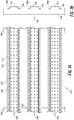
- the view of FIG. 7B depicts several furring strips having legs 710 disposed at the inner end of webs 730, and a face 720 disposed at the outer end of webs 730.
- Furring has traditionally been installed vertically. Horizontal furring may be desirable in building construction for various reasons, such as to enable a flexible or customizable layout for vertical panel joints, and/or to provide a regular and/or symmetrical layout of cladding fasteners independent of the location of vertical framing members.
- existing furring products typically cannot be installed horizontally because a horizontal configuration tends to cause water to collect above the furring strips, rather than draining downward.
- Existing furring products thus typically are installed vertically, at locations determined by the location and availability of vertical framing studs, resulting in relatively few options for the location of vertical panel joints.
- various embodiments of the present disclosure provide a furring system comprising multifunctional furring strips that can be installed in a horizontal orientation, a vertical orientation, or an orientation between horizontal and vertical, while providing desirable drainage, ventilation, and wind load resistance attributes in any such orientation.
- Furring strips described herein can be installed horizontally to a building substrate, and exterior cladding articles of various weights, such as fiber cement siding or the like, can be secured to the furring strips to create a rain screen system including an air gap between the exterior cladding and the building substrate.
- surface dimples can provide a capillary break, drainage channel, or ventilation space at one or more interfaces between the furring strips and the building substrate or exterior cladding.
- Certain embodiments of the furring strips disclosed herein have dimples with a combination of dimple height and dimple spacing configured to provide desirable drainage in a horizontal configuration, while also providing reliable wind load resistance and prevention of blowout or nail pull-through.
- certain embodiments of the furring strips disclosed herein may provide up to three gravity-assisted fluid flow paths (e.g., between the legs and a building substrate, between the face and a cladding, and/or through web openings).
- Drained furring tapes can be adhesive tapes having an outer surface with an array of raised drainage features.
- a length of furring tape can be applied to an outward-facing surface of a commercially available flat furring strip, such as a metal hat channel or wood furring strip, to produce a drained furring strip that can be installed in a horizontal configuration in a rainscreen system.
- FIGS. 1A-1D depict a first embodiment of a furring strip 100 incorporating drainage functionality.
- the furring strip 100 is a lineal structural member having a profile defined generally by legs 110, a face 120, and webs 130 disposed between and contiguous with the legs 110 and the face 120.
- the legs 110 are substantially planar and include leg dimples 115 spaced along the length of each leg 110.
- the face 120 is substantially planar and parallel to the legs 110, with face dimples 125 spaced in an array along the length and width of the face 120.
- Webs 130 extend between the lateral ends of the face 120 and the medial ends of the legs 110, with web openings 135 spaced along the length of the webs 130.
- the dimples 115, 125, and web openings 135 provide enhanced drainage and ventilation, as will be described in greater detail below.
- the furring strip 100 is configured to be installed adjacent to a building substrate to secure a cladding article, such as a fiber cement panel or the like, to the building substrate in a spaced configuration to form an air gap.
- the furring strip 100 is generally configured for installation such that the legs 110 and/or leg dimples 115 are adjacent to the building substrate along the length of the furring strip 100 and/or at various locations along the furring strip 100 (e.g., if the furring strip 100 is mounted to a plurality of discrete structural members such as studs, rather than to a sheathing or other continuous substrate), and the face 120 and/or face dimples 125 are adjacent to the cladding article, so as to form an air gap having a width determined by the height 132 of the furring strip 100 (as shown in FIG.
- Mechanical fastening means can be used to secure the legs 110 to the building substrate and to secure the cladding article to the face 120. Installation of strips such as furring strip 100 with cladding and building substrates is discussed in greater detail below with reference to FIGS. 7A-8B .
- the furring strip 100 can be made from any suitable material, for example, a metal such as steel, aluminum, or the like.
- the furring strip 100 comprises a single piece of steel of a suitable thickness to retain dimensional stability when coupled to a building substrate and a cladding article.
- the furring strip 100 can be manufactured from sheet steel, for example, bare metal sheet steel or corrosion-treated sheet steel, having a thickness between 20 gauge (0.0329 inches or 0.836 mm) and 16 gauge (0.0538 inches or 1.367 mm).
- the furring strip 100 can be manufactured by rolling, extruding, pressing, or the like.
- the furring strip 100 is manufactured by producing the dimples 115, 125 and punching, laser cutting, or otherwise creating the web openings 135 into a strip of sheet steel, and then forming the pre-textured strip with web openings 135 into the final channel shape using a roll form or the like.
- the metal material may further have a fine profile, or surface texture, on the outer surfaces 110a, 120a of the legs 110 and face 120, for example, to assist in the orientation of mechanical fasteners being driven through the furring strip 100 and prevent unintended lateral movement (e.g., "walking" or “wandering") of mechanical fastener tips when being driven through the furring strip 100.
- Each leg 110 has an outer leg surface 110a and an inner leg surface 110b.
- Each leg dimple 115 includes a recess 115a of the outer leg surface 110a, and a corresponding protrusion 115b of the inner leg surface 110b.
- the face 120 has an outer face surface 120a and an inner face surface 120b.
- Each face dimple 125 includes a protrusion 125a of the outer face surface 120a, and a corresponding recess 125b of the inner face surface 120b.
- Dimples are generally characterized by a dimple spacing 126 and a dimple height 127.
- the dimple spacing 126 is the lateral displacement (e.g., in the x or z direction of FIGS. 1A-1D ) between the centers of adjacent dimples 115, 125.
- Dimple spacing may refer to the spacing of face dimples 125 along the width of the face 120, and/or the spacing of leg dimples 115 or face dimples 125 along the length of the leg 110 or face 120.
- the dimple height 127 is the vertical displacement (e.g., in the y direction of FIGS. 1A-1D ) between the outer face surface 120a and the center of the protrusion 125a.
- the dimple height 127 can similarly be measured as the vertical displacement between the inner leg surface 110b and the center of the protrusion 115b.
- the webs 130 are disposed between the legs 110 and the face 120 and extend from the legs 110 and face 120 at an intersection defined by a web angle ⁇ between the web 130 and either the outer leg surface 110a or the inner face surface 120b.
- the web angle ⁇ can be acute, right, or obtuse, however, an obtuse web angle web angle ⁇ greater than 90° may advantageously facilitate drainage when the furring strip 100 is installed against a vertical building substrate, such that the direction of gravity is substantially along the x axis.
- the height 132 of the furring strip 100 is at least partially dependent on the length of the webs 130 and on the web angle ⁇ .
- the angle ⁇ is approximately 95°.
- the example furring strip 100 shown in FIGS. 1A-1D has a height 132 of 0.75 inches (19.05 mm).
- the dimples of the furring strip 100 have a diameter of 0.3125 inches (7.938 mm) and a dimple height of 127 of 0.0626 inches (1.5875 mm).
- the face dimples 125 are arranged in a regular grid pattern with a dimple spacing 126 of 0.5625 inches (14.288 mm) along both the length and the width of the face 120. Thus, the face dimples 125 may cover 20%-28% of the face 120.
- the leg dimples 115 are similarly spaced at 0.5625 inches (14.288 mm) along the length of the legs 110.
- the web openings 135 are oval, elliptical, or obround, having a total length (e.g., a dimension along the length of the furring strip 100) of 1.125 inches (28.575mm) and a height (e.g., a dimension normal to the length and in the plane of the web 130) of 0.275 inches (6.985 mm), with adjacent web openings 135 being spaced 1 inch (25.4 mm) apart along the length of the web 130.
- the web openings 135 of each web 130 may be positioned and/or sized to correspond to the web openings 135 of the opposing web 130 so as to facilitate drainage of water through both webs 130 when the furring strip 100 is installed horizontally. These dimensions represent a single example configuration.
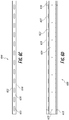
- a second embodiment of a furring strip 200 similarly comprises two legs 210, a face 220, and two webs 230 connecting the legs 210 and the face 220.
- the furring strip 200 is substantially similar in structure and function to the furring strip 100 depicted in FIGS. 1A-1D , including spaced leg dimples 215 and face dimples 225 arranged in an array of four rows. Unlike the furring strip 100 of FIGS.
- the face dimples 225 of the furring strip 200 are arranged in a plurality of offset rows, wherein each row is displaced along the length of the furring strip 200, relative to each adjacent row, e.g., by 0.140625 inches (3.57 mm).
- the lengthwise dimple spacing 226 of the face dimples 225 is 0.5625 inches (14.288 mm)
- the offset between adjacent rows results in a configuration in which no two face dimples 225 are centered on a line along the width of the furring strip 200.
- the furring strip 200 can comprise a metal such as steel.
- the furring strip 200 can be made of a sheet steel having a width between 20 gauge and 16 gauge, and can be manufactured by rolling, extruding, pressing, or the like.
- the furring strip 200 is manufactured by producing the dimples 215, 225 and punching the web openings 235 into a strip of sheet steel, and then forming the pre-textured and pre-punched strip into the final channel shape using a roll form or the like.
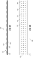
- FIGS. 3A-3D depict a third embodiment of a furring strip 300 incorporating drainage functionality similar to the furring strips 100, 200 described above.
- the furring strip 300 includes legs 310, a face 320, and webs 330 connecting the legs 310 and the face 320.
- the face 320 includes face dimples 325 in a regular array configuration. Similar to the furring strip 100 of FIGS. 1A-1D , the face dimples 325 have a diameter of 0.3125 inches (7.938 mm) and are spaced along the length and width of the face 320 at 0.5625 inches (14.288 mm).
- the furring strip 300 has a total height (as measured from the inner surface 310b of the legs 310 to the center of the protrusion 325a of the face dimples 325) of 0.375 inches (9.525 mm).
- the face dimples 325 have a height of 0.125 inches (3.175 mm). Due to the relatively shorter height of the webs 330 relative to the webs 130, 230 of FIGS. 1A-2D , web openings 335 of the furring strip 300 have a length of 1.125 inches (28.575 mm) and a height of 0.071 inches (1.8034 mm).
- the legs 310 of the furring strip 300 are substantially flat and do not include leg dimples as shown in FIGS. 1A-2D .
- the inner surface 310b of the legs 310 is positioned directly against a building substrate when installed, and drainage occurs primarily through the web openings 335 and face dimples 325.
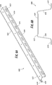
- FIGS. 4A-4D depict a fourth embodiment of a furring strip 400.
- the furring strip 400 includes legs 410, a face 420, and webs 430 disposed between the legs 410 and the face 420. Similar to the furring strip 100 depicted in FIGS. 1A-1D , the furring strip 400 has a height of 0.75 inches (19.05 mm) with a dimple diameter of 0.3125 inches (7.938 mm) and a dimple height of 0.0626 inches (1.5875 mm). As compared to the furring strip 100 of FIGS.
- the furring strip 400 has a relatively larger dimple spacing, with face dimples 425 spaced 0.84 inches (21.336 mm) apart along the width of the face 420, and 1 inch (25.4 mm) apart along the length of the face 420. Accordingly, each row of face dimples 425 (e.g., along the width of the face 420) is a row of 3 dimples, rather than 4 dimples as in the furring strip 100 of FIGS. 1A-1D . Accordingly, the face dimples 425 may cover 16%-20% of the face 420.
- the spacing of leg dimples 415 can be independent of the face dimple 425 spacing, and may be the same or different from the leg dimple 415 spacing of FIGS. 1A-1D .
- apertures 413, 423 can be provided in the legs 410 and face 420 respectively, to accommodate mechanical fasteners for securing the furring strip 400 to a building substrate or cladding article. Apertures 413, 423 may be desirable, for example, where relatively thick materials are used in the construction of the furring strip 400.
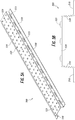
- FIGS. 5A-5D depict a fifth embodiment of a furring strip 500.
- the furring strip 500 includes legs 510 including apertures 413 for mechanical fasteners, a face 520 including face dimples 525 and apertures 523 for mechanical fasteners, and webs 530 disposed between the legs 510 and the face 520, the webs 530 including web openings 535.
- the furring strip 500 has a height of 0.75 inches (19.05 mm) with a dimple diameter of 0.3125 inches (7.938 mm) and a dimple height 127 of 0.0626 inches (1.5875 mm). Similar to the furring strip 300 depicted in FIGS.
- the legs 510 of the furring strip 500 are substantially flat and do not include leg dimples.
- the webs 530 may be longer relative to those of the furring strip 400.
- a furring strip 600 can have substantially flat legs 610 and a substantially flat face 620 without dimples. In such embodiments, drainage can occur primarily through web openings 635 in webs 630.
- the furring strip 600 has a height of 0.875 inches (22.225 mm).
- additional features of the profile of the furring strip 600 can include ridges 622 at lateral edges of the face 620 of the furring strip 600.
- the example furring strip 600 may optionally include apertures 613 and 623 to accommodate mechanical fasteners, as described with reference to previous examples above.
- FIGS. 7A-8B example furring strip installation methods and configurations will be described.
- the furring strips 700, 800 depicted in FIGS. 7A-8B are consistent with the furring strip 400 depicted and described with reference to FIGS. 4A-4D , it will be appreciated that the configurations and methods of FIGS. 7A-8B can equally be implemented with any of the other furring strip embodiments depicted and described herein, for example, with reference to FIGS. 1A-3D and 5A-6D .
- an example structural furring system 750 includes one or more furring strips 700 attached in a horizontal orientation to a building substrate 760.
- the building substrate can include one or more of studs or other horizontal or vertical framing members, a planar exterior sheathing such as plywood or oriented strand board (OSB), a housewrap or other weather-resistant material, or any other building material to which an interior or exterior cladding is to be applied.
- the building substrate comprises vertically oriented studs in a laterally spaced configuration, for example, along an exterior wall of a building.
- the furring strips 700 can be mounted in a horizontal configuration as shown in FIGS. 7A-7B .
- the furring strips 700 can be mounted at any desired spacing, and can be fastened equally to the building substrate 760 by mechanical fasteners 765 for any stud spacing.
- each furring strip 700 includes legs 710 which are fastened to the building substrate 760 such that a face 720 of the furring strip 700 is spaced outward from the building substrate 760.
- a rain screen system 850 can further include one or more exterior cladding articles 870 secured to a building substrate 860 by furring strips 800.
- the furring strips 800 are fastened to the building substrate 860 by mechanical fasteners 865, such as screws, nails, or the like.
- Exterior cladding articles 870 for example, fiber cement cladding panels, vinyl cladding panels, or the like, can then be fastened to the furring strips 800 by mechanical fasteners 875 such as nails, screws, or the like, to create an air gap 855 as part of the rain screen system 850.
- mechanical fasteners 875 are configured to secure an exterior cladding article 870 to a furring strip 800, while mechanical fasteners 865 are configured to secure a furring strip 800 to a building substrate 860, it will be appreciated that mechanical fasteners 875 can be similar or different from mechanical fasteners 865, based at least in part on the materials comprising the building substrate 860, the furring strips 800, and the cladding articles 870.
- the method begins by placing a first furring strip 800 in a desired position for installation with the legs 810 and/or leg dimples 815 adjacent to the building substrate 860.
- the first furring strip 800 can then be secured to the building substrate 860, for example, by a plurality of mechanical fasteners 865 such as nails or screws, which may be driven through the legs 810 between the leg dimples 815 and/or through apertures within the legs 810.
- Further furring strips 800 may then be installed at a desired spacing to yield a configuration similar to the system 750 depicted in FIGS. 7A and 7B .
- one or more exterior cladding articles 870 are obtained.
- a first one of the exterior cladding articles 870 is placed into a desired position for installation, with an inner surface of the first exterior cladding article 870 adjacent to the face 820 and/or face dimples 825 of the furring strips 800.
- the first exterior cladding article 870 can then be secured to the furring strips 800, for example, by one or more mechanical fasteners 875 such as nails or screws, with may be driven through the face 820 and/or through apertures 823 within the face 820.
- Further exterior cladding articles 870 may then be installed at a desired spacing and/or adjacent to the first exterior cladding article 870 to yield a completed rain screen system 850.
- drainage functionality can be achieved by the application of a drainage layer 980a, such as an adhesive tape, to a furring strip 900 that has a substantially flat face 920 and substantially flat legs 910.
- the furring strip 900 can be a lineal metallic strip, for example, a commercially profile such as a hat channel, furring channel, u channel, or the like.
- the furring strip 900 can be a wooden furring strip having a generally rectangular cross-sectional profile.
- the example furring strip 900 of FIG. 9A includes ridges 922 at lateral edges of the face 920 adjacent to webs 930. Accordingly, the drainage layer 980a can advantageously allow existing vertical furring materials to be mounted in a horizontal configuration, thereby providing more flexible installation configurations.
- the example drainage layer 980a depicted in FIG. 9A comprises an adhesive tape including an inner surface 985 at least partially coated with a chemical adhesive, such as a glue, and a substantially planar outer surface 990 having one or more drainage features included thereon.
- the drainage features are generally round dimples 995a configured to provide a capillary break similar to the dimples depicted previously in FIGS. 1A-8B .
- a removable backing 987 can be coupled to the inner surface 985 to protect the chemical adhesive on the inner surface 985, and removed before attachment to the furring strip 900.
- the drainage layer 980a is coupled to the face 920 of the furring strip 900, the resulting combination is a furring strip 900 with integrated drainage functionality similar to other furring strip embodiments described herein.
- the outer surface 990 of a drainage layer 980b as shown in FIG. 9B includes drainage features 995b in the form of square or diamond-shaped protrusions from the outer surface 990.
- a drainage layer 980c includes drainage features 995c comprising oval, elliptical, or obround protrusions from the upper surface 990.
- the drainage features 995c are oriented along the width of the outer surface 990, such that a vertical drainage channel is created when the furring strip 900 ( FIG. 9A ) is installed in a horizontal configuration between a building substrate and a cladding article.
- a drainage layer 980d includes oval, elliptical, or obround drainage features 995d similar to the drainage features 995c depicted in FIG. 9C .
- the drainage features 995d are oriented diagonally on the outer surface 990.
- a furring strip 900 FIG. 9A
- the drainage layer 980d can be installed in either a horizontal or vertical configuration while still creating a diagonally downward drainage channel adjacent to an installed cladding article.
- FIG. 9E depicts an alternative embodiment of a drainage layer 980e including drainage features 995e in the form of alternating thicker and thinner portions of the drainage layer 980.
- the drainage features 995e are oriented along the width of the outer surface 990, such that a vertical drainage channel is created when the furring strip 900 ( FIG. 9A ) is installed in a horizontal configuration between a building substrate and a cladding article.
- drainage layers 980f, 980g for application with furring strips 900 can include drainage features 995f, 995g of different heights, for example, based on the furring strips 900 to be used with the drainage layers 980f, 980g.
- the drainage features 995g of FIG. 9G are relatively taller than the drainage features 995f of FIG. 9F .
- the drainage layer 980g will generally create a wider drainage and ventilation channel when installed with a cladding article, relative to the drainage layer 980f. Accordingly, in some implementations, it may be desirable to use the drainage layer 980g with a wood furring strip or a furring strip 900 as depicted in FIG.
- Wind load capacity is determined by calculating the applied load capacity in accordance with ASTM E-330, "The Standard Test Method for Structural Performance of Exterior Windows, Doors, Skylights and Curtain Walls by Uniform Static Air Pressure Difference.”
- the test measures the uniform static air pressure difference, inward and outward for which the building system and/or rainscreen system are designed to withstand under load conditions.
- the test monitors the displacement or change in dimensions of the system after the applied load has been removed.
- a series of wind load model deformation tests were carried out to determine the ability of the various furring strip configurations to withstand an outward loading consistent with expected wind load conditions.
- each of model furring strips 400, 500, and 600 was made from 16ga steel, and a 20ga version of strip 400 was additionally tested.
- each model furring strip 400, 500, 600, and the commercially available hat channel were fixed to two studs spaced 24 inches (0.6096 m) apart.
- Each model furring strip was subjected to test loads of 35 Ibf (155.7 N) and 44.4 Ibf (195.7 N), at a single point centered on the furring strip and between the studs.
- various embodiments of the furring strips provided herein can provide substantially improved flexibility and/or customizability of cladding installation configurations, while maintaining satisfactory drainage and resistance to wind load deformation.
Description
- The present disclosure generally relates to building construction materials and methods, and more particularly relates to cladding systems including furring.
- Cladding panels such as those made of fiber cement are frequently attached to the structural frame of a building to form a non-structural facade of the building. Furring strips are often disposed between the cladding panels and the building structure to form an air gap therebetween. The air gap creates a capillary break which allows for drainage and evaporation of moisture.
- Conventional furring strips can present a number of disadvantages. They typically must be installed in a vertical orientation so as to provide adequate drainage, as horizontally oriented furring strips can limit the drainage and drying capacity of a wall cavity behind a cladding. Lateral spacing and alignment of vertically oriented furring is generally relatively inflexible, being determined by the location and spacing of studs or other vertically oriented building substrate materials. In addition, the wind load rating on cladding panels fastened to conventional furring strips may be less than desirable. Nail withdrawal or pull through are common causes of cladding system failure. The document
WO 00/63506 A1 - The systems, methods, and devices described herein address one or more problems as described above and associated with current furring systems. The systems, methods and devices described herein have innovative aspects, no single one of which is indispensable or solely responsible for their desirable attributes. Without limiting the scope of the claims, the summary below describes some of the advantageous features.
- According to the present disclosure there is provided a furring strip as set out in appended
Claims 1 to 7. There is also provided a wall cladding system comprising a furring strip and at least one wall cladding panel as set out in appendedClaims - The present invention discloses a furring strip for mounting a wall cladding article to a building substrate according to
claim 1. - In some embodiments, each of the plurality of substantially planar legs comprises a plurality of protrusions configured to produce one or more drainage channels between the substantially planar legs and a building substrate secured to the substantially planar legs.
- In some embodiments, the dimples are arranged in a rectangular array on the substantially planar face with a spacing of at least 0.25 inches (6.35mm) and not greater than approximately 1 inch (2.54cm) between adjacent dimples. In some embodiments, the dimples extend to a height of between approximately 0.03125 inches (0.7938mm) and approximately 0.25 inches (6.35mm) relative to the outer side of the substantially planar face. In some embodiments, the dimples extend to a height of between approximately 0.0625 inches (1.5875 mm) and approximately 0.125 inches (3.175mm) relative to the outer side of the substantially planar face.
- In some embodiments, each of the substantially planar webs comprises a plurality of openings extending through the substantially planar web to accommodate water or air flow through the web. In some embodiments, each of the openings has a width between approximately 0.1 inches (2.54mm) and approximately 0.3 inches (7.62mm), and a length between approximately 0.5 inches (1.27cm) and 1.5 inches (3.81cm).
- In some embodiments, the furring strip comprises a rolled sheet metal. In some embodiments, the metal comprises steel having a thickness of at least 20 gauge (0.836 mm) and not greater than 16 gauge (1.367 mm). In some embodiments, a wind load of approximately 44.4 Ibf (195.7 N)at two or more fastening points along the face produces a deflection between 0 and I/240 inches, where I is the span distance, expressed in inches (I/609.6cm when expressed in cm), between the fastening points.
- The present invention also discloses a wall cladding system having a multifunction structural furring according to
claim 8. The wall cladding system comprises the furring strip as described above and at least one wall cladding panel. - In one particular embodiment, the furring strip of the wall cladding strip comprises a substantially planar face defined generally by a length and a width, the substantially planar face comprising a first edge and a second edge opposite the first edge along the width, the face comprising an array of convex dimples extending from an outer side of the substantially planar face; a plurality of substantially planar webs, each substantially planar web extending from the first edge or the second edge of the substantially planar face in a direction opposite the outer side, each substantially planar web comprising a plurality of openings extending through the substantially planar web to accommodate water or air flow through the substantially planar web; and a plurality of substantially planar legs parallel to the substantially planar face, each substantially planar leg extending from one of the plurality of substantially planar webs at an end opposite the substantially planar face, each substantially planar leg comprising a row of convex dimples extending from an inner side of the substantially planar leg opposite the substantially planar webs and substantially planar face, wherein the furring strip is mounted to the exterior of a building substrate by a plurality of mechanical fasteners such that the convex dimples of the substantially planar legs abut the building substrate and the length of the substantially planar face is in a horizontal orientation relative to the building substrate. The at least one wall cladding panel is mounted to the furring strip by one or more mechanical fasteners such that the convex dimples of the substantially planar face abut the wall cladding panel. An inner surface of the wall cladding panel, the outer side of the substantially planar face, and two or more of the dimples of the substantially planar face define a first gravity-assisted drainage flow path. The building substrate, the inner sides of the legs, and two or more of the dimples of the substantially planar legs define a second gravity-assisted drainage flow path.
- In one embodiment the furring strip of the wall cladding strip is made of a rolled sheet metal. In some embodiments, the rolled sheet metal comprises steel having a thickness of at least 20 gauge and not greater than 16 gauge. In some embodiments, the dimples are arranged in a rectangular array on the face with a spacing of at least 0.25 inches (6.35 mm) and not greater than approximately 1 inch (2.54cm) between adjacent dimples. In some embodiments, the dimples extend to a height of between 0.03125 inches (0.7938mm) and approximately 0.25 inches (6.35mm) relative to the outer side of the face. In some embodiments, the dimples extend to a height of between approximately 0.0625 inches (1.5875 mm) and approximately 0.125 inches (3.175mm) relative to the outer side of the face. In some embodiments, a wind load producing a force of 44.4 Ibf (195.7 N)at two or more adjacent mechanical fasteners mounting the wall cladding panel to the furring strip induces a deflection in the face between 0 and I/240 inches, where I is the span distance, expressed in inches (I/609.6cm when expressed in cm), between the two adjacent mechanical fasteners.
- In another embodiment, an adhesive drainage tape for a furring strip is described. The adhesive tape comprises a substantially planar tape defined generally by a length, a width, an inner surface, and an outer surface, the inner surface at least partially coated with a chemical adhesive, and an array of protrusions extending from the outer surface, the protrusions generally defined by a height relative to the outer surface and a spacing between adjacent protrusions. The adhesive tape is configured to be fixed by the chemical adhesive to a substantially flat face surface of a structural furring strip before an exterior cladding article is coupled to the furring strip such that, when the exterior cladding article is coupled to the furring strip, a gravity-assisted drainage flow path is defined by an inner surface of the wall cladding panel, the outer surface of the tape, and two or more of the protrusions.
- In some embodiments, the protrusions are arranged in a rectangular array on the outer surface with a spacing of at least 0.25 inches (6.35mm) and not greater than approximately 1 inch (2.54cm) between adjacent protrusions. In some embodiments, the protrusions extend to a height of between approximately 0.03125 inches (0.7938mm) and approximately 0.25 inches (6.35mm) relative to the outer surface. In some embodiments, the protrusions extend to a height of between approximately 0.0625 inches (1.5875 mm) and approximately 0.125 inches (3.175mm) relative to the outer surface. In some embodiments, the protrusions comprise dimples having a circular cross-section. In some embodiments, the width of the adhesive tape is selected to fit against a face of a hat channel furring strip.
- Certain embodiments of the present disclosure will now be described, by way of example only, with reference to the accompanying drawings. From figure to figure, the same or similar reference numerals are used to designate similar components of an illustrated embodiment.
-
FIG. 1A is a perspective view of a furring strip with drainage features in accordance with a first example embodiment. -
FIG. 1B is a cross-sectional profile view taken about theline 1B-1B ofFIG. 1A , illustrating an example configuration of drainage features incorporated therein. -
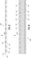
FIG. 1C is a side elevation view of the furring strip ofFIGS. 1A and 1B . -
FIG. 1D is a top plan view of the furring strip ofFIGS. 1A-1C . -
FIG. 2A is a perspective view of a furring strip with drainage features in accordance with a second example embodiment. -
FIG. 2B is an end profile view of the furring strip ofFIG. 2A , illustrating an example configuration of drainage features incorporated therein. -
FIG. 2C is a side elevation view of the furring strip ofFIGS. 2A and 2B . -
FIG. 2D is a top plan view of the furring strip ofFIGS. 2A-2C . -
FIG. 3A is a perspective view of a furring strip with drainage features in accordance with a third example embodiment. -
FIG. 3B is an end profile view of the furring strip ofFIG. 3A , illustrating an example configuration of drainage features incorporated therein. -
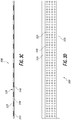
FIG. 3C is a side elevation view of the furring strip ofFIGS. 3A and 3B . -
FIG. 3D is a top plan view of the furring strip ofFIGS. 3A-3C . -
FIG. 4A is a perspective view of a furring strip with drainage features in accordance with a fourth example embodiment. -
FIG. 4B is an end profile view of the furring strip ofFIG. 4A , illustrating an example configuration of drainage features incorporated therein. -
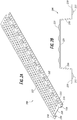
FIG. 4C is a side elevation view of the furring strip ofFIGS. 4A and 4B . -
FIG. 4D is a top plan view of the furring strip ofFIGS. 4A-4C . -
FIG. 5A is a perspective view of a furring strip with drainage features in accordance with a fifth example embodiment. -
FIG. 5B is an end profile view of the furring strip ofFIG. 5A , illustrating an example configuration of drainage features incorporated therein. -
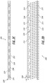
FIG. 5C is a side elevation view of the furring strip ofFIGS. 5A and 5B . -
FIG. 5D is a top plan view of the furring strip ofFIGS. 5A-5C . -
FIG. 6A is a perspective view of a furring strip with drainage functionality in accordance with a sixth example embodiment. -
FIG. 6B is an end profile view of the furring strip ofFIG. 6A , illustrating an example configuration of drainage features incorporated therein. -
FIG. 6C is a side elevation view of the furring strip ofFIGS. 6A and 6B . -
FIG. 6D is a top plan view of the furring strip ofFIGS. 6A-6C . -
FIG. 7A is a front elevation view of a structural furring system including a plurality of furring strips installed on a building substrate. -
FIG. 7B is a side profile view of the system ofFIG. 7A . -
FIG. 8A is a front elevation view of a rain screen system including cladding articles secured to the furring strips ofFIG. 7A . -
FIG. 8B is a side profile view of the system ofFIG. 8A . -
FIG. 9A is a perspective view of a furring strip not part of the invention and a textured adhesive tape configured to provide rain screen drainage functionality when applied to the furring strip. -
FIGS. 9B-9G depict alternative surface texture configurations of the adhesive tape depicted inFIG. 9A . - Although the present disclosure is described with reference to specific examples, it will be appreciated that the present disclosure may be embodied in many other forms.
- In the description which follows, like parts may be marked throughout the specification and drawings with the same reference numerals. The drawing figures are not necessarily to scale and certain features may be shown exaggerated in scale or in somewhat generalized or schematic form in the interest of clarity and conciseness.
- To assist in the description of various components of the furring systems described herein, the following coordinate terms are used (see, e.g.,
FIGS. 1A-1B ). A "length" of a furring strip generally refers to the longest dimension of the furring strip embodiments depicted. A "width" is the dimension normal to the length and parallel to the plane of the faces and legs of a furring strip. A "height" is the dimension normal to the length and width. For example, the perspective view ofFIG. 1A depicts a furring strip having a length along the direction of the z axis, a width along the direction of the x axis, and a height along the direction of the y axis. An "inner" surface or component is generally configured to be disposed proximal to and/or oriented toward a building substrate, and an "outer" surface or component is generally configured to be disposed distal to and/or oriented away from a building substrate. For example, the view ofFIG. 7B depicts several furringstrips having legs 710 disposed at the inner end ofwebs 730, and aface 720 disposed at the outer end ofwebs 730. Although certain dimensions will be provided for various components described and depicted herein, each of the furring strips and components thereof may be implemented with different dimensions in other embodiments, for example, by scaling the dimensions isotropically and/or by independently altering individual dimensions. - Furring has traditionally been installed vertically. Horizontal furring may be desirable in building construction for various reasons, such as to enable a flexible or customizable layout for vertical panel joints, and/or to provide a regular and/or symmetrical layout of cladding fasteners independent of the location of vertical framing members. However, existing furring products typically cannot be installed horizontally because a horizontal configuration tends to cause water to collect above the furring strips, rather than draining downward. Existing furring products thus typically are installed vertically, at locations determined by the location and availability of vertical framing studs, resulting in relatively few options for the location of vertical panel joints.
- Generally described, various embodiments of the present disclosure provide a furring system comprising multifunctional furring strips that can be installed in a horizontal orientation, a vertical orientation, or an orientation between horizontal and vertical, while providing desirable drainage, ventilation, and wind load resistance attributes in any such orientation. Furring strips described herein can be installed horizontally to a building substrate, and exterior cladding articles of various weights, such as fiber cement siding or the like, can be secured to the furring strips to create a rain screen system including an air gap between the exterior cladding and the building substrate. When the furring strips described herein are installed as part of a rain screen system, surface dimples can provide a capillary break, drainage channel, or ventilation space at one or more interfaces between the furring strips and the building substrate or exterior cladding. Certain embodiments of the furring strips disclosed herein have dimples with a combination of dimple height and dimple spacing configured to provide desirable drainage in a horizontal configuration, while also providing reliable wind load resistance and prevention of blowout or nail pull-through. For example, certain embodiments of the furring strips disclosed herein may provide up to three gravity-assisted fluid flow paths (e.g., between the legs and a building substrate, between the face and a cladding, and/or through web openings).
- Some embodiments not part of the present invention provide drained furring tape that can be applied to existing furring strips that lack sufficient drainage when installed horizontally. Drained furring tapes can be adhesive tapes having an outer surface with an array of raised drainage features. Thus, a length of furring tape can be applied to an outward-facing surface of a commercially available flat furring strip, such as a metal hat channel or wood furring strip, to produce a drained furring strip that can be installed in a horizontal configuration in a rainscreen system.
-
FIGS. 1A-1D depict a first embodiment of afurring strip 100 incorporating drainage functionality. Thefurring strip 100 is a lineal structural member having a profile defined generally bylegs 110, aface 120, andwebs 130 disposed between and contiguous with thelegs 110 and theface 120. Thelegs 110 are substantially planar and includeleg dimples 115 spaced along the length of eachleg 110. Similarly, theface 120 is substantially planar and parallel to thelegs 110, withface dimples 125 spaced in an array along the length and width of theface 120.Webs 130 extend between the lateral ends of theface 120 and the medial ends of thelegs 110, withweb openings 135 spaced along the length of thewebs 130. Thedimples web openings 135 provide enhanced drainage and ventilation, as will be described in greater detail below. - The
furring strip 100 is configured to be installed adjacent to a building substrate to secure a cladding article, such as a fiber cement panel or the like, to the building substrate in a spaced configuration to form an air gap. Thefurring strip 100 is generally configured for installation such that thelegs 110 and/orleg dimples 115 are adjacent to the building substrate along the length of thefurring strip 100 and/or at various locations along the furring strip 100 (e.g., if thefurring strip 100 is mounted to a plurality of discrete structural members such as studs, rather than to a sheathing or other continuous substrate), and theface 120 and/or facedimples 125 are adjacent to the cladding article, so as to form an air gap having a width determined by theheight 132 of the furring strip 100 (as shown inFIG. 1B ). Mechanical fastening means can be used to secure thelegs 110 to the building substrate and to secure the cladding article to theface 120. Installation of strips such asfurring strip 100 with cladding and building substrates is discussed in greater detail below with reference toFIGS. 7A-8B . - All or a portion of the
furring strip 100 can be made from any suitable material, for example, a metal such as steel, aluminum, or the like. In some embodiments, thefurring strip 100 comprises a single piece of steel of a suitable thickness to retain dimensional stability when coupled to a building substrate and a cladding article. For example, thefurring strip 100 can be manufactured from sheet steel, for example, bare metal sheet steel or corrosion-treated sheet steel, having a thickness between 20 gauge (0.0329 inches or 0.836 mm) and 16 gauge (0.0538 inches or 1.367 mm). In embodiments comprising sheet steel, thefurring strip 100 can be manufactured by rolling, extruding, pressing, or the like. In some embodiments, thefurring strip 100 is manufactured by producing thedimples web openings 135 into a strip of sheet steel, and then forming the pre-textured strip withweb openings 135 into the final channel shape using a roll form or the like. In some embodiments, the metal material may further have a fine profile, or surface texture, on theouter surfaces legs 110 andface 120, for example, to assist in the orientation of mechanical fasteners being driven through thefurring strip 100 and prevent unintended lateral movement (e.g., "walking" or "wandering") of mechanical fastener tips when being driven through thefurring strip 100. - As shown in greater detail in
FIG. 1B , several features of the profile of thefurring strip 100 are configured to provide enhanced drainage functionality. Eachleg 110 has anouter leg surface 110a and aninner leg surface 110b. Eachleg dimple 115 includes arecess 115a of theouter leg surface 110a, and acorresponding protrusion 115b of theinner leg surface 110b. Similarly, theface 120 has anouter face surface 120a and aninner face surface 120b. Eachface dimple 125 includes aprotrusion 125a of theouter face surface 120a, and acorresponding recess 125b of theinner face surface 120b. - Dimples are generally characterized by a
dimple spacing 126 and adimple height 127. As used herein, thedimple spacing 126 is the lateral displacement (e.g., in the x or z direction ofFIGS. 1A-1D ) between the centers ofadjacent dimples face 120, and/or the spacing ofleg dimples 115 or facedimples 125 along the length of theleg 110 orface 120. Thedimple height 127 is the vertical displacement (e.g., in the y direction ofFIGS. 1A-1D ) between theouter face surface 120a and the center of theprotrusion 125a. For aleg dimple 115, thedimple height 127 can similarly be measured as the vertical displacement between theinner leg surface 110b and the center of theprotrusion 115b. - The
webs 130 are disposed between thelegs 110 and theface 120 and extend from thelegs 110 and face 120 at an intersection defined by a web angle ϕ between theweb 130 and either theouter leg surface 110a or theinner face surface 120b. The web angle ϕ can be acute, right, or obtuse, however, an obtuse web angle web angle ϕ greater than 90° may advantageously facilitate drainage when thefurring strip 100 is installed against a vertical building substrate, such that the direction of gravity is substantially along the x axis. Thus, theheight 132 of thefurring strip 100, as generally defined by the vertical displacement between the center of theprotrusions 115b of theinner leg surface 110b and the center of theprotrusions 125a of theouter face surface 120a, is at least partially dependent on the length of thewebs 130 and on the web angle ϕ. In the example embodiment shown inFIGS. 1A-1D , the angle ϕ is approximately 95°. - The
example furring strip 100 shown inFIGS. 1A-1D has aheight 132 of 0.75 inches (19.05 mm). The dimples of thefurring strip 100 have a diameter of 0.3125 inches (7.938 mm) and a dimple height of 127 of 0.0626 inches (1.5875 mm). The face dimples 125 are arranged in a regular grid pattern with adimple spacing 126 of 0.5625 inches (14.288 mm) along both the length and the width of theface 120. Thus, the face dimples 125 may cover 20%-28% of theface 120. The leg dimples 115 are similarly spaced at 0.5625 inches (14.288 mm) along the length of thelegs 110. Theweb openings 135 are oval, elliptical, or obround, having a total length (e.g., a dimension along the length of the furring strip 100) of 1.125 inches (28.575mm) and a height (e.g., a dimension normal to the length and in the plane of the web 130) of 0.275 inches (6.985 mm), withadjacent web openings 135 being spaced 1 inch (25.4 mm) apart along the length of theweb 130. Theweb openings 135 of eachweb 130 may be positioned and/or sized to correspond to theweb openings 135 of the opposingweb 130 so as to facilitate drainage of water through bothwebs 130 when thefurring strip 100 is installed horizontally. These dimensions represent a single example configuration. - Referring now to
FIGS. 2A-2D , a second embodiment of afurring strip 200 similarly comprises twolegs 210, aface 220, and twowebs 230 connecting thelegs 210 and theface 220. Thefurring strip 200 is substantially similar in structure and function to thefurring strip 100 depicted inFIGS. 1A-1D , including spaced leg dimples 215 and facedimples 225 arranged in an array of four rows. Unlike thefurring strip 100 ofFIGS. 1A-1D , the face dimples 225 of thefurring strip 200 are arranged in a plurality of offset rows, wherein each row is displaced along the length of thefurring strip 200, relative to each adjacent row, e.g., by 0.140625 inches (3.57 mm). As the lengthwise dimple spacing 226 of the face dimples 225 is 0.5625 inches (14.288 mm), the offset between adjacent rows results in a configuration in which no two facedimples 225 are centered on a line along the width of thefurring strip 200. - Similar to the
furring strip 100 ofFIGS. 1A-1D , thefurring strip 200 can comprise a metal such as steel. For example, thefurring strip 200 can be made of a sheet steel having a width between 20 gauge and 16 gauge, and can be manufactured by rolling, extruding, pressing, or the like. In some embodiments, thefurring strip 200 is manufactured by producing thedimples web openings 235 into a strip of sheet steel, and then forming the pre-textured and pre-punched strip into the final channel shape using a roll form or the like. -
FIGS. 3A-3D depict a third embodiment of afurring strip 300 incorporating drainage functionality similar to thefurring strips furring strip 300 includeslegs 310, aface 320, andwebs 330 connecting thelegs 310 and theface 320. Theface 320 includes face dimples 325 in a regular array configuration. Similar to thefurring strip 100 ofFIGS. 1A-1D , the face dimples 325 have a diameter of 0.3125 inches (7.938 mm) and are spaced along the length and width of theface 320 at 0.5625 inches (14.288 mm). - The
furring strip 300 has a total height (as measured from theinner surface 310b of thelegs 310 to the center of theprotrusion 325a of the face dimples 325) of 0.375 inches (9.525 mm). The face dimples 325 have a height of 0.125 inches (3.175 mm). Due to the relatively shorter height of thewebs 330 relative to thewebs FIGS. 1A-2D ,web openings 335 of thefurring strip 300 have a length of 1.125 inches (28.575 mm) and a height of 0.071 inches (1.8034 mm). - In some embodiments, such as the
furring strip 300 shown inFIGS. 3A-3D , thelegs 310 of thefurring strip 300 are substantially flat and do not include leg dimples as shown inFIGS. 1A-2D . In such embodiments, theinner surface 310b of thelegs 310 is positioned directly against a building substrate when installed, and drainage occurs primarily through theweb openings 335 and face dimples 325. -
FIGS. 4A-4D depict a fourth embodiment of afurring strip 400. Thefurring strip 400 includeslegs 410, aface 420, andwebs 430 disposed between thelegs 410 and theface 420. Similar to thefurring strip 100 depicted inFIGS. 1A-1D , thefurring strip 400 has a height of 0.75 inches (19.05 mm) with a dimple diameter of 0.3125 inches (7.938 mm) and a dimple height of 0.0626 inches (1.5875 mm). As compared to thefurring strip 100 ofFIGS. 1A-1D , thefurring strip 400 has a relatively larger dimple spacing, withface dimples 425 spaced 0.84 inches (21.336 mm) apart along the width of theface face 420. Accordingly, each row of face dimples 425 (e.g., along the width of the face 420) is a row of 3 dimples, rather than 4 dimples as in thefurring strip 100 ofFIGS. 1A-1D . Accordingly, the face dimples 425 may cover 16%-20% of theface 420. The spacing ofleg dimples 415 can be independent of theface dimple 425 spacing, and may be the same or different from theleg dimple 415 spacing ofFIGS. 1A-1D . - In some embodiments, such as the
example furring strip 400,apertures legs 410 and face 420 respectively, to accommodate mechanical fasteners for securing thefurring strip 400 to a building substrate or cladding article.Apertures furring strip 400. -
FIGS. 5A-5D depict a fifth embodiment of afurring strip 500. Thefurring strip 500 includeslegs 510 includingapertures 413 for mechanical fasteners, aface 520 including face dimples 525 andapertures 523 for mechanical fasteners, andwebs 530 disposed between thelegs 510 and theface 520, thewebs 530 includingweb openings 535. Similar to thefurring strip 400 depicted inFIGS. 4A-4D , thefurring strip 500 has a height of 0.75 inches (19.05 mm) with a dimple diameter of 0.3125 inches (7.938 mm) and adimple height 127 of 0.0626 inches (1.5875 mm). Similar to thefurring strip 300 depicted inFIGS. 3A-3D , thelegs 510 of thefurring strip 500 are substantially flat and do not include leg dimples. Thus, to achieve the same height as thefurring strip 400 ofFIGS. 4A-4D , thewebs 530 may be longer relative to those of thefurring strip 400. - In some embodiments, as shown for example in
FIGS. 6A-6D , afurring strip 600 can have substantiallyflat legs 610 and a substantiallyflat face 620 without dimples. In such embodiments, drainage can occur primarily throughweb openings 635 inwebs 630. In the example ofFIGS. 6A-6D , thefurring strip 600 has a height of 0.875 inches (22.225 mm). In some aspects, additional features of the profile of thefurring strip 600 can includeridges 622 at lateral edges of theface 620 of thefurring strip 600. Theexample furring strip 600 may optionally includeapertures - Referring now to
FIGS. 7A-8B , example furring strip installation methods and configurations will be described. Although thefurring strips FIGS. 7A-8B are consistent with thefurring strip 400 depicted and described with reference toFIGS. 4A-4D , it will be appreciated that the configurations and methods ofFIGS. 7A-8B can equally be implemented with any of the other furring strip embodiments depicted and described herein, for example, with reference toFIGS. 1A-3D and5A-6D . - As shown in
FIGS. 7A and 7B , an examplestructural furring system 750 includes one ormore furring strips 700 attached in a horizontal orientation to abuilding substrate 760. In various embodiments, the building substrate can include one or more of studs or other horizontal or vertical framing members, a planar exterior sheathing such as plywood or oriented strand board (OSB), a housewrap or other weather-resistant material, or any other building material to which an interior or exterior cladding is to be applied. In the examplestructural furring system 750, the building substrate comprises vertically oriented studs in a laterally spaced configuration, for example, along an exterior wall of a building. - Conveniently, and in contrast to existing vertically oriented furring, the
furring strips 700 can be mounted in a horizontal configuration as shown inFIGS. 7A-7B . In a horizontal configuration, thefurring strips 700 can be mounted at any desired spacing, and can be fastened equally to thebuilding substrate 760 bymechanical fasteners 765 for any stud spacing. As shown inFIGS. 7A-7B , eachfurring strip 700 includeslegs 710 which are fastened to thebuilding substrate 760 such that aface 720 of thefurring strip 700 is spaced outward from thebuilding substrate 760. - With reference to
FIGS. 8A-8B , arain screen system 850 can further include one or moreexterior cladding articles 870 secured to abuilding substrate 860 byfurring strips 800. As in thestructural furring system 750 ofFIGS. 7A-7B , thefurring strips 800 are fastened to thebuilding substrate 860 bymechanical fasteners 865, such as screws, nails, or the like.Exterior cladding articles 870, for example, fiber cement cladding panels, vinyl cladding panels, or the like, can then be fastened to thefurring strips 800 bymechanical fasteners 875 such as nails, screws, or the like, to create anair gap 855 as part of therain screen system 850. Becausemechanical fasteners 875 are configured to secure anexterior cladding article 870 to afurring strip 800, whilemechanical fasteners 865 are configured to secure afurring strip 800 to abuilding substrate 860, it will be appreciated thatmechanical fasteners 875 can be similar or different frommechanical fasteners 865, based at least in part on the materials comprising thebuilding substrate 860, thefurring strips 800, and thecladding articles 870. - With continued reference to
FIGS. 8A-8B , an example method of installing a cladding will now be described. The method begins by placing afirst furring strip 800 in a desired position for installation with thelegs 810 and/orleg dimples 815 adjacent to thebuilding substrate 860. Thefirst furring strip 800 can then be secured to thebuilding substrate 860, for example, by a plurality ofmechanical fasteners 865 such as nails or screws, which may be driven through thelegs 810 between the leg dimples 815 and/or through apertures within thelegs 810.Further furring strips 800 may then be installed at a desired spacing to yield a configuration similar to thesystem 750 depicted inFIGS. 7A and 7B . When a plurality offurring strips 800 have been installed, one or moreexterior cladding articles 870 are obtained. A first one of theexterior cladding articles 870 is placed into a desired position for installation, with an inner surface of the firstexterior cladding article 870 adjacent to theface 820 and/or facedimples 825 of the furring strips 800. The firstexterior cladding article 870 can then be secured to thefurring strips 800, for example, by one or moremechanical fasteners 875 such as nails or screws, with may be driven through theface 820 and/or throughapertures 823 within theface 820. Furtherexterior cladding articles 870 may then be installed at a desired spacing and/or adjacent to the firstexterior cladding article 870 to yield a completedrain screen system 850. - Referring now to
FIG. 9A , not part of the invention, drainage functionality can be achieved by the application of adrainage layer 980a, such as an adhesive tape, to afurring strip 900 that has a substantiallyflat face 920 and substantiallyflat legs 910. In various embodiments, thefurring strip 900 can be a lineal metallic strip, for example, a commercially profile such as a hat channel, furring channel, u channel, or the like. In other embodiments, thefurring strip 900 can be a wooden furring strip having a generally rectangular cross-sectional profile. Similar to thefurring strip 600 ofFIGS. 6A-6D , theexample furring strip 900 ofFIG. 9A includesridges 922 at lateral edges of theface 920 adjacent towebs 930. Accordingly, thedrainage layer 980a can advantageously allow existing vertical furring materials to be mounted in a horizontal configuration, thereby providing more flexible installation configurations. - The
example drainage layer 980a depicted inFIG. 9A comprises an adhesive tape including aninner surface 985 at least partially coated with a chemical adhesive, such as a glue, and a substantially planarouter surface 990 having one or more drainage features included thereon. For example, inFIG. 9A , the drainage features are generallyround dimples 995a configured to provide a capillary break similar to the dimples depicted previously inFIGS. 1A-8B . Aremovable backing 987 can be coupled to theinner surface 985 to protect the chemical adhesive on theinner surface 985, and removed before attachment to thefurring strip 900. Thus, when thedrainage layer 980a is coupled to theface 920 of thefurring strip 900, the resulting combination is afurring strip 900 with integrated drainage functionality similar to other furring strip embodiments described herein. - Referring now to
FIGS. 9B-9G , not part of the invention, a variety of shapes and configurations of drainage features can be implemented with the adhesive drainage layers described herein. For example, theouter surface 990 of a drainage layer 980b as shown inFIG. 9B includes drainage features 995b in the form of square or diamond-shaped protrusions from theouter surface 990. - In a further example, as shown in
FIG. 9C , adrainage layer 980c includes drainage features 995c comprising oval, elliptical, or obround protrusions from theupper surface 990. The drainage features 995c are oriented along the width of theouter surface 990, such that a vertical drainage channel is created when the furring strip 900 (FIG. 9A ) is installed in a horizontal configuration between a building substrate and a cladding article. - Referring now to
FIG. 9D , adrainage layer 980d includes oval, elliptical, orobround drainage features 995d similar to the drainage features 995c depicted inFIG. 9C . In thedrainage layer 980d, the drainage features 995d are oriented diagonally on theouter surface 990. Thus, a furring strip 900 (FIG. 9A ) with thedrainage layer 980d can be installed in either a horizontal or vertical configuration while still creating a diagonally downward drainage channel adjacent to an installed cladding article. -
FIG. 9E depicts an alternative embodiment of adrainage layer 980e includingdrainage features 995e in the form of alternating thicker and thinner portions of the drainage layer 980. The drainage features 995e are oriented along the width of theouter surface 990, such that a vertical drainage channel is created when the furring strip 900 (FIG. 9A ) is installed in a horizontal configuration between a building substrate and a cladding article. - Referring jointly to
FIGS. 9F and 9G , drainage layers 980f, 980g for application with furring strips 900 (FIG. 9A ) can include drainage features 995f, 995g of different heights, for example, based on thefurring strips 900 to be used with the drainage layers 980f, 980g. The drainage features 995g ofFIG. 9G are relatively taller than the drainage features 995f ofFIG. 9F . Thus, thedrainage layer 980g will generally create a wider drainage and ventilation channel when installed with a cladding article, relative to thedrainage layer 980f. Accordingly, in some implementations, it may be desirable to use thedrainage layer 980g with a wood furring strip or afurring strip 900 as depicted inFIG. 9A , which does not have any integrated drainage functionality, and to use thedrainage layer 980f with a furring strip that already includes limited drainage and/or ventilation functionality (e.g., thefurring strip 600 depicted inFIGS. 6A-6D , which has web openings 638 but no drainage features on thelegs 610 or face 620). - Wind load capacity is determined by calculating the applied load capacity in accordance with ASTM E-330, "The Standard Test Method for Structural Performance of Exterior Windows, Doors, Skylights and Curtain Walls by Uniform Static Air Pressure Difference." The test measures the uniform static air pressure difference, inward and outward for which the building system and/or rainscreen system are designed to withstand under load conditions. The test monitors the displacement or change in dimensions of the system after the applied load has been removed. In accordance with the test, a series of wind load model deformation tests were carried out to determine the ability of the various furring strip configurations to withstand an outward loading consistent with expected wind load conditions. In a first set of model tests, the
model furring strips TABLE 1: Results of wind load deformation tests of example furring strips Maximum Deformation Commercially Available Hat Channel 0.010 inches (0.254 mm) Furring Strip 1000.013 inches (0.3302 mm) Furring Strip 2000.014 inches (0.3556 mm) Furring Strip 3000.057 inches (1.448 mm) - In a second set of model tests, the
furring strips model furring strips strip 400 was additionally tested. Thus, eachmodel furring strip TABLE 2: Results of wind load deformation tests of example furring strips 1 x 35 Ibf Max. Deflection 1 x 44.4 Ibf Max. Deflection 7 x 35 Ibf Max. Deflection 3 x 44.4 Ibf Max. Deflection Commercial Hat Channel 0.019 inches (0.4826 mm) 0.023 inches (0.5842 mm) 0.058 inches (1.4732 mm) 0.041 inches (1.041 mm) Furring Strip 4000.025 inches (0.635 mm) 0.031 inches (0.7874 mm) 0.072 inches (1.8288 mm) 0.051 inches (1.2954 mm) Strip 400, 20ga0.041 inches (1.041 mm) 0.052 inches (1.3208 mm) 0.110 inches (2.794 mm) 0.083 inches (2.1082 mm) Furring Strip 5000.024 inches (0.6096 mm) 0.030 inches (0.762 mm) 0.068 inches (1.7272 mm) 0.049 inches (1.2446 mm) Furring Strip 6000.021 inches (0.5334 mm) 0.026 inches (0.6604 mm) 0.063 inches (1.6002 mm) 0.046 inches (1.1684 mm) - Thus, as shown by the wind load deformation testing results above, various embodiments of the furring strips provided herein can provide substantially improved flexibility and/or customizability of cladding installation configurations, while maintaining satisfactory drainage and resistance to wind load deformation.
- Certain features that are described in this disclosure in the context of separate implementations can also be implemented in combination in a single implementation. Conversely, various features that are described in the context of a single implementation can also be implemented in multiple implementations separately or in any suitable subcombination. Moreover, although features may be described above as acting in certain combinations, one or more features from a claimed combination can, in some cases, be excised from the combination, and the combination may be claimed as any subcombination or variation of any subcombination.
- Moreover, while methods may be depicted in the drawings or described in the specification in a particular order, such methods need not be performed in the particular order shown or in sequential order, and that all methods need not be performed, to achieve desirable results. Other methods that are not depicted or described can be incorporated in the example methods and processes. For example, one or more additional methods can be performed before, after, simultaneously, or between any of the described methods. Further, the methods may be rearranged or reordered in other implementations. Also, the separation of various system components in the implementations described above should not be understood as requiring such separation in all implementations, and it should be understood that the described components and systems can generally be integrated together in a single product or packaged into multiple products. Additionally, other implementations are within the scope of this disclosure.
- Conditional language, such as "can," "could," "might," or "may," unless specifically stated otherwise, or otherwise understood within the context as used, is generally intended to convey that certain embodiments include or do not include, certain features, elements, and/or steps. Thus, such conditional language is not generally intended to imply that features, elements, and/or steps are in any way required for one or more embodiments.
- Conjunctive language such as the phrase "at least one of X, Y, and Z," unless specifically stated otherwise, is otherwise understood with the context as used in general to convey that an item, term, etc. may be either X, Y, or Z. Thus, such conjunctive language is not generally intended to imply that certain embodiments require the presence of at least one of X, at least one of Y, and at least one of Z.
- Although making and using various embodiments are discussed in detail below, it should be appreciated that the description provides many inventive concepts that may be embodied in a wide variety of contexts. The specific aspects and embodiments discussed herein are merely illustrative of ways to make and use the systems and methods disclosed herein and do not limit the scope of the disclosure. The systems and methods described herein may be used for mounting cladding articles to building substrates and are described herein with reference to this application. However, it will be appreciated that the disclosure is not limited to this particular field of use.
- Some embodiments have been described in connection with the accompanying drawings. The figures are drawn to scale, but such scale should not be limiting, since dimensions and proportions other than what are shown are contemplated and are within the scope of the disclosed inventions. Distances, angles, etc. are merely illustrative and do not necessarily bear an exact relationship to actual dimensions and layout of the devices illustrated. Components can be added, removed, and/or rearranged. Further, the disclosure herein of any particular feature, aspect, method, property, characteristic, quality, attribute, element, or the like in connection with various embodiments can be used in all other embodiments set forth herein. Additionally, it will be recognized that any methods described herein may be practiced using any device suitable for performing the recited steps.
- While a number of embodiments and variations thereof have been described in detail, other modifications and methods of using the same will be apparent to those of skill in the art. Accordingly, it should be understood that various applications, modifications, materials, and substitutions can be made of equivalents without departing from the scope of the claims.
Claims (9)
- A furring strip (100) for mounting a wall cladding article to a building substrate (860), the furring strip (100) comprising:a substantially planar face (120) defined generally by a length and a width, the substantially planar face (120) comprising a first edge and a second edge opposite the first edge along the width;a plurality of substantially planar webs (130), each substantially planar web (130) extending from the first edge or the second edge of the substantially planar face (120); anda plurality of substantially planar legs (110) parallel to the substantially planar face (120), each substantially planar leg (110) extending from one of the plurality of substantially planar webs (130) at an end opposite the substantially planar face (120);wherein the substantially planar face (120) comprises a plurality of protrusions (125) configured to produce one or more drainage channels between the substantially planar face (120) and a cladding article secured to the substantially planar face (120), wherein the protrusions (125) comprise an array of dimples extending from an outer side of the substantially planar face (120) and wherein said drainage channels define at least one gravity-assisted fluid flow path when the furring strip (100) is mounted in a horizontal or vertical orientation.
- A furring strip (100) as claimed in Claim 1, wherein each of the plurality of substantially planar legs (110) comprises a plurality of protrusions (115) configured to produce one or more drainage channels between the substantially planar legs (110) and a building substrate (860) secured to the substantially planar legs (110).
- A furring strip (100) as claimed in any one of the preceding claims, wherein the dimples of the substantially planar face (120) are arranged in a rectangular array on the substantially planar face (120) with a spacing of at least 0.25 inches (6.35mm) and not greater than approximately 1 inch (2.54cm) between adjacent dimples.
- A furring strip (100) as claimed in any one of the preceding claims, wherein the dimples of the substantially planar face (120) extend to a height of between approximately 0.03125 inches (0.7938mm) and approximately 0.25 inches (6.35mm) relative to the outer side of the substantially planar face (120).
- A furring strip (100) as claimed in any one of the preceding claims, wherein each of the substantially planar webs (130) comprises a plurality of openings (135) extending through the substantially planar web (130) to accommodate water or air flow through the substantially planar web (130).
- A furring strip (100) as claimed in any one of the preceding claims, wherein each of the openings has a width between approximately 0.1 inches (2.54mm) and approximately 0.3 inches (7.62mm), and a length between approximately 0.5 inches (1.27cm) and 1.5 inches (3.81cm).
- A furring strip (100) as claimed in any one of the preceding claims, wherein the furring strip (100) comprises rolled sheet steel having a thickness of at least 20 gauge (0.836 mm) and not greater than 16 gauge (1.367 mm).
- A wall cladding system having a multifunction structural furring, the wall cladding system comprising a furring strip (100) as claimed in any one of Claims 1 to 7 and at least
one wall cladding panel (870),wherein the furring strip (100) is mounted to the exterior of a building substrate (860) such that the substantially planar legs (110) abut the building substrate (860); andat least one wall cladding panel (870) mounted to the furring strip (100) such that the plurality of protrusions (125) of the substantially planar face (120) abut the wall cladding panel (870) ;wherein an inner surface of the wall cladding panel (870), the outer side of the substantially planar face (120), and two or more of the protrusions (125) of the substantially planar face (120) define a first gravity-assisted drainage flow path. - A wall cladding system having a multifunction structural furring,
the wall cladding system comprising a furring strip (100) as claimed in any one of Claims 2 to 7 and
at least one wall cladding panel (870),wherein the furring strip (100) is mounted to the exterior of a building substrate (860) such that the plurality of protrusions (115) of the substantially planar legs (110) abut the building substrate (860); andthe at least one wall cladding panel (870) is mounted to the furring strip (100) such that the plurality of protrusions (125) of the substantially planar face (120) abut the wall cladding panel (870);wherein an inner surface of the wall cladding panel (870), the outer side of the substantially planar face (120), and two or more of the protrusions (125) of the substantially planar face (120) define a first gravity-assisted drainage flow path; andwherein the building substrate, the inner sides of the substantially planar legs (110), and two or more of the protrusions (115) of the substantially planar legs (110) define a second gravity-assisted drainage flow path.
Applications Claiming Priority (2)
| Application Number | Priority Date | Filing Date | Title |
|---|---|---|---|
| US201762478980P | 2017-03-30 | 2017-03-30 | |
| PCT/EP2018/058267 WO2018178324A1 (en) | 2017-03-30 | 2018-03-29 | Multifunction structural furring system |
Publications (2)
| Publication Number | Publication Date |
|---|---|
| EP3601701A1 EP3601701A1 (en) | 2020-02-05 |
| EP3601701B1 true EP3601701B1 (en) | 2021-06-16 |
Family
ID=62044652
Family Applications (1)
| Application Number | Title | Priority Date | Filing Date |
|---|---|---|---|
| EP18719449.3A Active EP3601701B1 (en) | 2017-03-30 | 2018-03-29 | Multifunction structural furring system |
Country Status (4)
| Country | Link |
|---|---|
| US (2) | US20200362574A1 (en) |
| EP (1) | EP3601701B1 (en) |
| AU (1) | AU2018246349B2 (en) |
| WO (1) | WO2018178324A1 (en) |
Families Citing this family (9)
| Publication number | Priority date | Publication date | Assignee | Title |
|---|---|---|---|---|
| US9963887B2 (en) * | 2014-02-14 | 2018-05-08 | Norwood Architecture, Inc. | System and method for a vented and water control siding, vented and water control sheathing and vented and water control trim-board |
| CA3037878A1 (en) * | 2016-09-23 | 2018-03-29 | Armstrong World Industries, Inc. | Panel system and support member for use with the same |
| WO2019113246A1 (en) * | 2017-12-05 | 2019-06-13 | Louisiana-Pacific Corporation | Lap and panel siding with ventilation elements |
| USD869693S1 (en) | 2018-02-15 | 2019-12-10 | Tuf-Tite, Inc. | Tactile tile |
| DK3626909T3 (en) * | 2018-09-20 | 2021-04-12 | Weland Ab | PLANE TYPE FLOOR AND A PROFILE PLANK FOR SUCH A FLOOR |
| IT201900019142A1 (en) * | 2019-10-17 | 2021-04-17 | Stefano Bonetti | Wall profile |
| US11286676B2 (en) | 2020-02-19 | 2022-03-29 | Knight Wall Systems | Termination girts and related systems and methods |
| US11603666B2 (en) * | 2020-09-28 | 2023-03-14 | Gregory P. Albracht | Wall sheathing system |
| USD985802S1 (en) * | 2021-05-24 | 2023-05-09 | Super Stud Building Products, Inc. | Isolated resilient channel |
Family Cites Families (101)
| Publication number | Priority date | Publication date | Assignee | Title |
|---|---|---|---|---|
| GB124709A (en) * | 1918-03-25 | 1919-06-19 | Ettore Caretta | Improvements in or relating to Girders. |
| US1545168A (en) * | 1924-12-04 | 1925-07-07 | Bethlehem Steel Corp | Beam and its method of manufacture |
| GB373699A (en) * | 1931-03-18 | 1932-06-02 | Curry Ora Walper | Improvements in wall and ceiling construction |
| US2664179A (en) * | 1949-04-27 | 1953-12-29 | Jacob M Gwynne | Nailable metal structural member |
| US2853870A (en) * | 1956-08-06 | 1958-09-30 | John B Sinner | Removable wall facing panels |
| US3318056A (en) * | 1957-03-25 | 1967-05-09 | Cue Thompson & Company | Ventilating wall construction with stud location indicators |
| US3129792A (en) * | 1960-08-31 | 1964-04-21 | Jacob M Gwynne | Nailable metal structural members |
| US3196763A (en) * | 1960-10-05 | 1965-07-27 | Washington Aluminum Company In | Panel structure |
| US3333379A (en) * | 1964-02-21 | 1967-08-01 | Nat Gypsum Co | Resilient furring channel |
| US3381439A (en) * | 1965-10-21 | 1968-05-07 | United States Gypsum Co | Structural member |
| CH461074A (en) * | 1967-09-28 | 1968-08-15 | Kantorowicz Josef | Insert frame for parts of surface cladding |
| US3477187A (en) * | 1968-01-19 | 1969-11-11 | Albert A Fruman | Wallboard mounting channel |
| US3807101A (en) * | 1972-08-18 | 1974-04-30 | J Cole | Building structure |
| US3832813A (en) * | 1972-08-21 | 1974-09-03 | M Hindman | Skirting for mobile homes |
| US3849961A (en) * | 1973-03-26 | 1974-11-26 | J Gwynne | T-clip truss and rafter system of roof construction |
| US3888087A (en) * | 1973-04-11 | 1975-06-10 | Oivind Lorentzen Activities In | Foundation wall protective sheet |
| US3962066A (en) * | 1974-01-30 | 1976-06-08 | Barber-Webb | Resilient liner for an electrolytic cell |
| SE394478B (en) * | 1974-10-16 | 1977-06-27 | Interoc Fasad Ab | PROFILE RAIL OF THIN PLATE FOR USE AS A DISTANCE, STRENGTHENING AND LOAD-TAKING CONSTRUCTION ELEMENTS IN HEAT-INSULATED BUILDING PARTS |
| DE2518629B2 (en) * | 1975-04-26 | 1977-07-21 | Aiko Vertriebs GmbH M Matthes, 2000 Norderstedt | RAIL FOR SUBSTRUCTURE OF FACADE PANELS |
| DE2705725C3 (en) * | 1977-02-11 | 1981-04-09 | Otto Prof.Dr.-Ing. 6100 Darmstadt Jungbluth | Multi-layer, fire-resistant gate |
| US4092810A (en) * | 1977-03-16 | 1978-06-06 | Sumner John S | Domical structure |
| US4245443A (en) * | 1979-05-18 | 1981-01-20 | Beechen Paul R | Seepage control device |
| AT361968B (en) * | 1979-05-23 | 1981-04-10 | Hulek Anton | GUIDELINES OR THE LIKE |
| DE3024672A1 (en) * | 1980-06-30 | 1982-01-28 | Jens Ing.(grad.) 6458 Rodenbach Drefahl | ROOF COVER |
| US4545291A (en) * | 1984-03-08 | 1985-10-08 | Klauer Manufacturing Company | Roofline ventilators |
| US4578915A (en) * | 1984-03-12 | 1986-04-01 | National Gypsum Company | Exterior wall |
| US4691494A (en) * | 1985-06-28 | 1987-09-08 | Gwynne Jacob M | Metal framing system |
| US5094051A (en) * | 1990-08-14 | 1992-03-10 | The Lamparter Organization, Inc. | Wall panel mounting system |
| US5217319A (en) * | 1991-05-24 | 1993-06-08 | Advantage Metal Systems, Inc. | Metal tactile edge-warning strip |
| US5326609A (en) * | 1992-06-25 | 1994-07-05 | Metalines | Expansion joint fire barrier |
| NO930392D0 (en) * | 1992-09-23 | 1993-02-04 | Isola As | DEVICE FOR PROTECTIVE PLATE, SPECIAL FOR FLOOR |
| US5285615A (en) * | 1992-10-26 | 1994-02-15 | Angeles Metal Systems | Thermal metallic building stud |
| GB2272662C (en) * | 1992-11-21 | 2007-05-08 | Hadley Ind Plc | Sheet material, method of producing same and rolls for use in the method |
| JPH06226889A (en) * | 1993-02-05 | 1994-08-16 | Sky Alum Co Ltd | Panel material and composite panel using the same |
| US5592796A (en) * | 1994-12-09 | 1997-01-14 | Landers; Leroy A. | Thermally-improved metallic framing assembly |
| US5570555A (en) * | 1995-01-19 | 1996-11-05 | Ferguson; Gary | Double batted roof structure |
| US5687538A (en) * | 1995-02-14 | 1997-11-18 | Super Stud Building Products, Inc. | Floor joist with built-in truss-like stiffner |
| WO1997036068A1 (en) * | 1996-03-22 | 1997-10-02 | John Allan Trenerry | Elongate structural member |
| US5628154A (en) * | 1995-08-11 | 1997-05-13 | Gavette; James A. | Modular construction for a geodesic dome |
| SE504012C2 (en) * | 1995-09-07 | 1996-10-21 | Hellsten Mikael Ab | Beam |
| SE506666C2 (en) * | 1996-03-12 | 1998-01-26 | Lindab Ab | Elongated support element |
| US5820296A (en) * | 1996-05-10 | 1998-10-13 | Goughnour; R. Robert | Prefabricated vertical earth drain and method of making the same |
| US5826390A (en) * | 1996-05-28 | 1998-10-27 | Sacks Industrial Corp. | Building wall membrane |
| US6939599B2 (en) * | 1996-09-13 | 2005-09-06 | Brian H. Clark | Structural dimple panel |
| US5918998A (en) * | 1996-10-18 | 1999-07-06 | Pourmand; Tooraj | Joint for three-dimensional framed structures for interior and construction use |
| US6112476A (en) * | 1997-11-12 | 2000-09-05 | Masonry Accessories, Llc | Masonry weep hole insert |
| AUPP980399A0 (en) * | 1999-04-16 | 1999-05-13 | James Hardie International Finance B.V. | Method and apparatus for attaching building sheets |
| EP1087061B1 (en) * | 1999-09-27 | 2007-09-05 | Kick TG Holding B.V. | Paving tile for guidance of blind persons |
| US6298620B1 (en) * | 2000-04-10 | 2001-10-09 | Michael Hatzinikolas | Moisture control panel |
| US7690862B2 (en) * | 2000-07-03 | 2010-04-06 | Astra Capital Incorporated | Quick connect transit boarding platform panel |
| US6868639B1 (en) * | 2000-08-16 | 2005-03-22 | Ray R. Gunthardt | Force resistant architecture |
| JP2002088935A (en) * | 2000-09-14 | 2002-03-27 | Nichiha Corp | Vertical-joint joiner for external facing material |
| US6698710B1 (en) * | 2000-12-20 | 2004-03-02 | Portland Cement Association | System for the construction of insulated concrete structures using vertical planks and tie rails |
| JP2004346482A (en) * | 2001-05-18 | 2004-12-09 | Daicel Chem Ind Ltd | Form made of recycled resin |
| US20030014935A1 (en) * | 2001-07-18 | 2003-01-23 | Bodnar Ernest R. | Sheet metal stud and composite construction panel and method |
| US8234836B2 (en) * | 2003-08-05 | 2012-08-07 | Jeffrey A. Anderson | Method of manufacturing a metal framing member |
| US8261497B2 (en) * | 2004-09-27 | 2012-09-11 | Metadome, Llc | Embedment tile with replaceable top plate |
| US7698858B2 (en) * | 2003-11-10 | 2010-04-20 | Ewald Dörken Ag | Membrane for the protection of buildings |
| US7137224B2 (en) * | 2004-02-16 | 2006-11-21 | Quality Edge, Inc. | Vented soffit panel and method for buildings and like |
| NZ549407A (en) * | 2004-02-27 | 2009-04-30 | James Hardie Int Finance Bv | Batten mounting water management system |
| US6987928B2 (en) * | 2004-05-14 | 2006-01-17 | Chris Shields | Recirculating air snow melting pad system |
| ES2321625T3 (en) * | 2004-06-17 | 2009-06-09 | HEIMBACH GMBH & CO. KG | INSTALLATION OF ACOUSTIC INSULATION FOR A WALL, ROOF OR FLOOR COATING. |
| US8028557B2 (en) * | 2004-09-08 | 2011-10-04 | The Bradbury Company, Inc. | Methods and apparatus for forming stiffening structures in a strip material |
| US7743578B2 (en) * | 2004-09-09 | 2010-06-29 | Edmondson Dennis L | Slotted metal stud with supplemental flanges |
| US7621079B2 (en) * | 2005-01-14 | 2009-11-24 | Fukuvi Usa, Inc. | Water drainage component |
| US7712273B2 (en) * | 2005-01-25 | 2010-05-11 | Illinois Tool Works Inc. | Thermal breaker structures for use with roof decking assemblies |
| US20090249743A1 (en) * | 2006-01-17 | 2009-10-08 | Bodnar Ernest R | Stud with lengthwise indented grooves, and with intervening planar surfaces, and method |
| US8191323B2 (en) * | 2006-03-16 | 2012-06-05 | Turner Bruce H | Cable protection sleeve for building framing |
| CA2756354C (en) * | 2006-05-18 | 2012-10-09 | Sur-Stud Structural Technology Inc. | Light steel structural member and method of producing same |
| US7765761B2 (en) * | 2006-09-22 | 2010-08-03 | Johns Manville | Polymer-based composite structural sheathing board and wall and/or ceiling system |
| JP5599191B2 (en) * | 2007-03-08 | 2014-10-01 | ジェイムズ ハーディー テクノロジー リミテッド | Building system |
| US20100146893A1 (en) * | 2007-03-20 | 2010-06-17 | David Peter Dickinson | Cladding system for buildings |
| US8590217B2 (en) * | 2007-03-21 | 2013-11-26 | James Hardie Technology Limited | Framed wall construction and method |
| CA2594220C (en) * | 2007-06-15 | 2008-11-18 | Joao Pascoa Fernandes | Moisture removal system |
| CA2638468C (en) * | 2007-08-09 | 2016-09-13 | Benjamin Obdyke Incorporated | Water-resistive barrier exterior wall or roof assembly and method of applying the barrier |
| GB2475138B (en) * | 2007-10-03 | 2012-05-16 | Steven Caffall Finch | Modular flooring panel, e.g. for temporary mezzanine floors in railway arches |
| US8938926B2 (en) * | 2007-11-15 | 2015-01-27 | Worthington Armstrong Venture | Wall liner |
| US8919061B2 (en) * | 2008-02-06 | 2014-12-30 | Brentwood Industries, Inc. | Moisture drainage spacer panel for building walls |
| CA2724403C (en) * | 2008-05-15 | 2013-08-27 | Saint-Gobain Performance Plastics Corporation | Wall and ceiling sound damping mounts and channels |
| US7681362B1 (en) * | 2008-08-11 | 2010-03-23 | Averitt Randal K | Vented panel connector |
| US8109124B2 (en) * | 2008-12-31 | 2012-02-07 | Simpson Strong-Tie Company | Split strap |
| US8522509B2 (en) * | 2009-03-09 | 2013-09-03 | Custom Building Products, Inc. | Mortarless tile installation system and method for installing tiles |
| EP3061368A1 (en) * | 2009-03-17 | 2016-08-31 | Tac-Fast Systems SA | Covering module |
| USD618365S1 (en) * | 2009-06-18 | 2010-06-22 | James Crane | Reinforced steel stud |
| US8973329B2 (en) * | 2009-08-20 | 2015-03-10 | James Hardie Technology Limited | Building system with multi-function insulation barrier |
| AT508799B1 (en) * | 2009-10-06 | 2014-01-15 | Sihga Handels Gmbh | TILING LIST WHICH IS PART OF A SUB-CONSTRUCTION |
| US8307610B2 (en) * | 2010-05-25 | 2012-11-13 | Landers Leroy A | Insulative metallic channel and construction assembly |
| USD751733S1 (en) * | 2010-08-16 | 2016-03-15 | Clark Western Dietrich Building Systems Llc | Framing member |
| CA2950282C (en) * | 2010-12-30 | 2020-05-12 | The Grid Company Llc | System, method and apparatus for patterned ceiling suspension |
| CA2763058C (en) * | 2012-01-05 | 2014-10-14 | Cascadia Windows Ltd. | Thermally insulative spacer and methods involving use of same |
| US20130291465A1 (en) * | 2012-05-04 | 2013-11-07 | Garland Industries, Inc. | Vented wall girts |
| US20140119815A1 (en) * | 2012-11-01 | 2014-05-01 | Todd A. Brady | Exterior Wall Assembly Systems |
| US20140147611A1 (en) * | 2012-11-23 | 2014-05-29 | Sure Flash Llc | Conformable Preconditioned Adhesive Sealing Tape |
| CA2871377C (en) * | 2013-11-18 | 2019-09-10 | Certainteed Corporation | Integrated siding rainscreen and stacking clip |
| USD782709S1 (en) * | 2015-04-29 | 2017-03-28 | American Roll Form Products Corp. | Metal plank |
| SE540537C2 (en) * | 2015-07-03 | 2018-09-25 | Hallberg Per | Metod och anordning för att reducera flöde av jordluft till inomhusluft i en byggnad |
| CA2942597C (en) * | 2015-10-05 | 2018-11-13 | Michael Wayne Ukrainetz | Corrugated furring strips and use of same in upright wall structures |
| JP6432488B2 (en) * | 2015-11-12 | 2018-12-05 | 株式会社ダイフク | Storehouse |
| US10519673B2 (en) * | 2015-12-23 | 2019-12-31 | James Hardie Technology Limited | Building cladding and method for preparing same |
| US10724232B2 (en) * | 2016-03-22 | 2020-07-28 | Glavloc Build Systems Limited | Construction system |
| US10174503B2 (en) * | 2017-02-03 | 2019-01-08 | Atlas Roofing Corporation | Construction sheathing and methods of making and using same |
-
2018
- 2018-03-29 AU AU2018246349A patent/AU2018246349B2/en active Active
- 2018-03-29 WO PCT/EP2018/058267 patent/WO2018178324A1/en unknown
- 2018-03-29 US US16/603,201 patent/US20200362574A1/en not_active Abandoned
- 2018-03-29 EP EP18719449.3A patent/EP3601701B1/en active Active
- 2018-03-29 US US15/940,715 patent/US10815669B2/en active Active
Also Published As
| Publication number | Publication date |
|---|---|
| US10815669B2 (en) | 2020-10-27 |
| US20200362574A1 (en) | 2020-11-19 |
| US20180283013A1 (en) | 2018-10-04 |
| AU2018246349A1 (en) | 2019-09-19 |
| EP3601701A1 (en) | 2020-02-05 |
| AU2018246349B2 (en) | 2024-02-15 |
| WO2018178324A1 (en) | 2018-10-04 |
Similar Documents
| Publication | Publication Date | Title |
|---|---|---|
| EP3601701B1 (en) | Multifunction structural furring system | |
| US6688069B2 (en) | Vertical slide clip | |
| US10221575B2 (en) | Panel siding product | |
| US8640415B2 (en) | Fire-rated wall construction product | |
| US9359772B2 (en) | Wall panel assembly | |
| US20080250738A1 (en) | Light weight metal framing member | |
| US10519673B2 (en) | Building cladding and method for preparing same | |
| CA2871377C (en) | Integrated siding rainscreen and stacking clip | |
| US10233651B2 (en) | Building system | |
| US20120251758A1 (en) | Heat insulation material | |
| CA2958693C (en) | Drywall to acoustical ceiling tiles transition trims | |
| EP3482010A1 (en) | Drywall sheet end joint | |
| US9790686B1 (en) | Triangular stud shaft wall system | |
| US11156002B2 (en) | Self-spacing lap siding product | |
| US20090031645A1 (en) | Architectural Covering and Method | |
| US11225799B2 (en) | Self-spacing lap siding product | |
| JP6994014B2 (en) | Airtight material and airtight structure of the building | |
| JP2022520979A (en) | Building studs, wall structures with such building studs, and methods for forming wall structures. | |
| US20220042319A1 (en) | Self-spacing lap siding product | |
| US11408169B2 (en) | Z-shaped bracket for wood backing and fireproofing | |
| US20210404177A1 (en) | Combination lath/rainscreen assemblies and methods of installation and manufacture | |
| CA3000921C (en) | A building article and methods for preparing same | |
| TH1901007228A (en) | corrugated construction parts | |
| SE1750297A1 (en) | A sandwich panel system |
Legal Events
| Date | Code | Title | Description |
|---|---|---|---|
| STAA | Information on the status of an ep patent application or granted ep patent |
Free format text: STATUS: UNKNOWN |
|
| STAA | Information on the status of an ep patent application or granted ep patent |
Free format text: STATUS: THE INTERNATIONAL PUBLICATION HAS BEEN MADE |
|
| PUAI | Public reference made under article 153(3) epc to a published international application that has entered the european phase |
Free format text: ORIGINAL CODE: 0009012 |
|
| STAA | Information on the status of an ep patent application or granted ep patent |
Free format text: STATUS: REQUEST FOR EXAMINATION WAS MADE |
|
| 17P | Request for examination filed |
Effective date: 20191029 |
|
| AK | Designated contracting states |
Kind code of ref document: A1 Designated state(s): AL AT BE BG CH CY CZ DE DK EE ES FI FR GB GR HR HU IE IS IT LI LT LU LV MC MK MT NL NO PL PT RO RS SE SI SK SM TR |
|
| AX | Request for extension of the european patent |
Extension state: BA ME |
|
| DAV | Request for validation of the european patent (deleted) | ||
| DAX | Request for extension of the european patent (deleted) | ||
| GRAP | Despatch of communication of intention to grant a patent |
Free format text: ORIGINAL CODE: EPIDOSNIGR1 |
|
| STAA | Information on the status of an ep patent application or granted ep patent |
Free format text: STATUS: GRANT OF PATENT IS INTENDED |
|
| INTG | Intention to grant announced |
Effective date: 20210201 |
|
| GRAS | Grant fee paid |
Free format text: ORIGINAL CODE: EPIDOSNIGR3 |
|
| GRAA | (expected) grant |
Free format text: ORIGINAL CODE: 0009210 |
|
| STAA | Information on the status of an ep patent application or granted ep patent |
Free format text: STATUS: THE PATENT HAS BEEN GRANTED |
|
| AK | Designated contracting states |
Kind code of ref document: B1 Designated state(s): AL AT BE BG CH CY CZ DE DK EE ES FI FR GB GR HR HU IE IS IT LI LT LU LV MC MK MT NL NO PL PT RO RS SE SI SK SM TR |
|
| REG | Reference to a national code |
Ref country code: GB Ref legal event code: FG4D |
|
| REG | Reference to a national code |
Ref country code: CH Ref legal event code: EP |
|
| REG | Reference to a national code |
Ref country code: DE Ref legal event code: R096 Ref document number: 602018018685 Country of ref document: DE |
|
| REG | Reference to a national code |
Ref country code: AT Ref legal event code: REF Ref document number: 1402451 Country of ref document: AT Kind code of ref document: T Effective date: 20210715 |
|
| REG | Reference to a national code |
Ref country code: IE Ref legal event code: FG4D |
|
| REG | Reference to a national code |
Ref country code: LT Ref legal event code: MG9D |
|
| PG25 | Lapsed in a contracting state [announced via postgrant information from national office to epo] |
Ref country code: HR Free format text: LAPSE BECAUSE OF FAILURE TO SUBMIT A TRANSLATION OF THE DESCRIPTION OR TO PAY THE FEE WITHIN THE PRESCRIBED TIME-LIMIT Effective date: 20210616 Ref country code: LT Free format text: LAPSE BECAUSE OF FAILURE TO SUBMIT A TRANSLATION OF THE DESCRIPTION OR TO PAY THE FEE WITHIN THE PRESCRIBED TIME-LIMIT Effective date: 20210616 Ref country code: FI Free format text: LAPSE BECAUSE OF FAILURE TO SUBMIT A TRANSLATION OF THE DESCRIPTION OR TO PAY THE FEE WITHIN THE PRESCRIBED TIME-LIMIT Effective date: 20210616 Ref country code: BG Free format text: LAPSE BECAUSE OF FAILURE TO SUBMIT A TRANSLATION OF THE DESCRIPTION OR TO PAY THE FEE WITHIN THE PRESCRIBED TIME-LIMIT Effective date: 20210916 |
|
| REG | Reference to a national code |
Ref country code: AT Ref legal event code: MK05 Ref document number: 1402451 Country of ref document: AT Kind code of ref document: T Effective date: 20210616 |
|
| REG | Reference to a national code |
Ref country code: NL Ref legal event code: MP Effective date: 20210616 |
|
| PG25 | Lapsed in a contracting state [announced via postgrant information from national office to epo] |
Ref country code: GR Free format text: LAPSE BECAUSE OF FAILURE TO SUBMIT A TRANSLATION OF THE DESCRIPTION OR TO PAY THE FEE WITHIN THE PRESCRIBED TIME-LIMIT Effective date: 20210917 Ref country code: NO Free format text: LAPSE BECAUSE OF FAILURE TO SUBMIT A TRANSLATION OF THE DESCRIPTION OR TO PAY THE FEE WITHIN THE PRESCRIBED TIME-LIMIT Effective date: 20210916 Ref country code: LV Free format text: LAPSE BECAUSE OF FAILURE TO SUBMIT A TRANSLATION OF THE DESCRIPTION OR TO PAY THE FEE WITHIN THE PRESCRIBED TIME-LIMIT Effective date: 20210616 Ref country code: SE Free format text: LAPSE BECAUSE OF FAILURE TO SUBMIT A TRANSLATION OF THE DESCRIPTION OR TO PAY THE FEE WITHIN THE PRESCRIBED TIME-LIMIT Effective date: 20210616 Ref country code: RS Free format text: LAPSE BECAUSE OF FAILURE TO SUBMIT A TRANSLATION OF THE DESCRIPTION OR TO PAY THE FEE WITHIN THE PRESCRIBED TIME-LIMIT Effective date: 20210616 |
|
| PG25 | Lapsed in a contracting state [announced via postgrant information from national office to epo] |
Ref country code: SM Free format text: LAPSE BECAUSE OF FAILURE TO SUBMIT A TRANSLATION OF THE DESCRIPTION OR TO PAY THE FEE WITHIN THE PRESCRIBED TIME-LIMIT Effective date: 20210616 Ref country code: SK Free format text: LAPSE BECAUSE OF FAILURE TO SUBMIT A TRANSLATION OF THE DESCRIPTION OR TO PAY THE FEE WITHIN THE PRESCRIBED TIME-LIMIT Effective date: 20210616 Ref country code: ES Free format text: LAPSE BECAUSE OF FAILURE TO SUBMIT A TRANSLATION OF THE DESCRIPTION OR TO PAY THE FEE WITHIN THE PRESCRIBED TIME-LIMIT Effective date: 20210616 Ref country code: EE Free format text: LAPSE BECAUSE OF FAILURE TO SUBMIT A TRANSLATION OF THE DESCRIPTION OR TO PAY THE FEE WITHIN THE PRESCRIBED TIME-LIMIT Effective date: 20210616 Ref country code: RO Free format text: LAPSE BECAUSE OF FAILURE TO SUBMIT A TRANSLATION OF THE DESCRIPTION OR TO PAY THE FEE WITHIN THE PRESCRIBED TIME-LIMIT Effective date: 20210616 Ref country code: PT Free format text: LAPSE BECAUSE OF FAILURE TO SUBMIT A TRANSLATION OF THE DESCRIPTION OR TO PAY THE FEE WITHIN THE PRESCRIBED TIME-LIMIT Effective date: 20211018 Ref country code: NL Free format text: LAPSE BECAUSE OF FAILURE TO SUBMIT A TRANSLATION OF THE DESCRIPTION OR TO PAY THE FEE WITHIN THE PRESCRIBED TIME-LIMIT Effective date: 20210616 Ref country code: CZ Free format text: LAPSE BECAUSE OF FAILURE TO SUBMIT A TRANSLATION OF THE DESCRIPTION OR TO PAY THE FEE WITHIN THE PRESCRIBED TIME-LIMIT Effective date: 20210616 Ref country code: AT Free format text: LAPSE BECAUSE OF FAILURE TO SUBMIT A TRANSLATION OF THE DESCRIPTION OR TO PAY THE FEE WITHIN THE PRESCRIBED TIME-LIMIT Effective date: 20210616 |
|
| PG25 | Lapsed in a contracting state [announced via postgrant information from national office to epo] |
Ref country code: PL Free format text: LAPSE BECAUSE OF FAILURE TO SUBMIT A TRANSLATION OF THE DESCRIPTION OR TO PAY THE FEE WITHIN THE PRESCRIBED TIME-LIMIT Effective date: 20210616 |
|
| REG | Reference to a national code |
Ref country code: DE Ref legal event code: R097 Ref document number: 602018018685 Country of ref document: DE |
|
| PLBE | No opposition filed within time limit |
Free format text: ORIGINAL CODE: 0009261 |
|
| STAA | Information on the status of an ep patent application or granted ep patent |
Free format text: STATUS: NO OPPOSITION FILED WITHIN TIME LIMIT |
|
| PG25 | Lapsed in a contracting state [announced via postgrant information from national office to epo] |
Ref country code: DK Free format text: LAPSE BECAUSE OF FAILURE TO SUBMIT A TRANSLATION OF THE DESCRIPTION OR TO PAY THE FEE WITHIN THE PRESCRIBED TIME-LIMIT Effective date: 20210616 |
|
| 26N | No opposition filed |
Effective date: 20220317 |
|
| PG25 | Lapsed in a contracting state [announced via postgrant information from national office to epo] |
Ref country code: AL Free format text: LAPSE BECAUSE OF FAILURE TO SUBMIT A TRANSLATION OF THE DESCRIPTION OR TO PAY THE FEE WITHIN THE PRESCRIBED TIME-LIMIT Effective date: 20210616 |
|
| PG25 | Lapsed in a contracting state [announced via postgrant information from national office to epo] |
Ref country code: IT Free format text: LAPSE BECAUSE OF FAILURE TO SUBMIT A TRANSLATION OF THE DESCRIPTION OR TO PAY THE FEE WITHIN THE PRESCRIBED TIME-LIMIT Effective date: 20210616 |
|
| PG25 | Lapsed in a contracting state [announced via postgrant information from national office to epo] |
Ref country code: MC Free format text: LAPSE BECAUSE OF FAILURE TO SUBMIT A TRANSLATION OF THE DESCRIPTION OR TO PAY THE FEE WITHIN THE PRESCRIBED TIME-LIMIT Effective date: 20210616 |
|
| REG | Reference to a national code |
Ref country code: CH Ref legal event code: PL |
|
| REG | Reference to a national code |
Ref country code: BE Ref legal event code: MM Effective date: 20220331 |
|
| PG25 | Lapsed in a contracting state [announced via postgrant information from national office to epo] |
Ref country code: LU Free format text: LAPSE BECAUSE OF NON-PAYMENT OF DUE FEES Effective date: 20220329 Ref country code: LI Free format text: LAPSE BECAUSE OF NON-PAYMENT OF DUE FEES Effective date: 20220331 Ref country code: IE Free format text: LAPSE BECAUSE OF NON-PAYMENT OF DUE FEES Effective date: 20220329 Ref country code: CH Free format text: LAPSE BECAUSE OF NON-PAYMENT OF DUE FEES Effective date: 20220331 |
|
| PG25 | Lapsed in a contracting state [announced via postgrant information from national office to epo] |
Ref country code: BE Free format text: LAPSE BECAUSE OF NON-PAYMENT OF DUE FEES Effective date: 20220331 |
|
| PGFP | Annual fee paid to national office [announced via postgrant information from national office to epo] |
Ref country code: FR Payment date: 20230208 Year of fee payment: 6 |
|
| PGFP | Annual fee paid to national office [announced via postgrant information from national office to epo] |
Ref country code: GB Payment date: 20230202 Year of fee payment: 6 Ref country code: DE Payment date: 20230131 Year of fee payment: 6 |
|
| P01 | Opt-out of the competence of the unified patent court (upc) registered |
Effective date: 20230427 |
|
| REG | Reference to a national code |
Ref country code: DE Ref legal event code: R081 Ref document number: 602018018685 Country of ref document: DE Owner name: JAMES HARDIE TECHNOLOGY, LTD.,, IE Free format text: FORMER OWNER: JAMES HARDIE TECHNOLOGY LIMITED, DUBLIN, IE |