EP3601059B1 - Aircraft lighting systems and methods - Google Patents
Aircraft lighting systems and methods Download PDFInfo
- Publication number
- EP3601059B1 EP3601059B1 EP18719293.5A EP18719293A EP3601059B1 EP 3601059 B1 EP3601059 B1 EP 3601059B1 EP 18719293 A EP18719293 A EP 18719293A EP 3601059 B1 EP3601059 B1 EP 3601059B1
- Authority
- EP
- European Patent Office
- Prior art keywords
- light
- light unit
- unit
- attribute
- measurement device
- Prior art date
- Legal status (The legal status is an assumption and is not a legal conclusion. Google has not performed a legal analysis and makes no representation as to the accuracy of the status listed.)
- Active
Links
Images



Classifications
-
- B—PERFORMING OPERATIONS; TRANSPORTING
- B64—AIRCRAFT; AVIATION; COSMONAUTICS
- B64D—EQUIPMENT FOR FITTING IN OR TO AIRCRAFT; FLIGHT SUITS; PARACHUTES; ARRANGEMENT OR MOUNTING OF POWER PLANTS OR PROPULSION TRANSMISSIONS IN AIRCRAFT
- B64D47/00—Equipment not otherwise provided for
- B64D47/02—Arrangements or adaptations of signal or lighting devices
-
- H—ELECTRICITY
- H05—ELECTRIC TECHNIQUES NOT OTHERWISE PROVIDED FOR
- H05B—ELECTRIC HEATING; ELECTRIC LIGHT SOURCES NOT OTHERWISE PROVIDED FOR; CIRCUIT ARRANGEMENTS FOR ELECTRIC LIGHT SOURCES, IN GENERAL
- H05B45/00—Circuit arrangements for operating light-emitting diodes [LED]
- H05B45/20—Controlling the colour of the light
- H05B45/22—Controlling the colour of the light using optical feedback
-
- H—ELECTRICITY
- H05—ELECTRIC TECHNIQUES NOT OTHERWISE PROVIDED FOR
- H05B—ELECTRIC HEATING; ELECTRIC LIGHT SOURCES NOT OTHERWISE PROVIDED FOR; CIRCUIT ARRANGEMENTS FOR ELECTRIC LIGHT SOURCES, IN GENERAL
- H05B47/00—Circuit arrangements for operating light sources in general, i.e. where the type of light source is not relevant
- H05B47/10—Controlling the light source
- H05B47/105—Controlling the light source in response to determined parameters
-
- H—ELECTRICITY
- H05—ELECTRIC TECHNIQUES NOT OTHERWISE PROVIDED FOR
- H05B—ELECTRIC HEATING; ELECTRIC LIGHT SOURCES NOT OTHERWISE PROVIDED FOR; CIRCUIT ARRANGEMENTS FOR ELECTRIC LIGHT SOURCES, IN GENERAL
- H05B47/00—Circuit arrangements for operating light sources in general, i.e. where the type of light source is not relevant
- H05B47/10—Controlling the light source
- H05B47/105—Controlling the light source in response to determined parameters
- H05B47/11—Controlling the light source in response to determined parameters by determining the brightness or colour temperature of ambient light
-
- H—ELECTRICITY
- H05—ELECTRIC TECHNIQUES NOT OTHERWISE PROVIDED FOR
- H05B—ELECTRIC HEATING; ELECTRIC LIGHT SOURCES NOT OTHERWISE PROVIDED FOR; CIRCUIT ARRANGEMENTS FOR ELECTRIC LIGHT SOURCES, IN GENERAL
- H05B47/00—Circuit arrangements for operating light sources in general, i.e. where the type of light source is not relevant
- H05B47/10—Controlling the light source
- H05B47/175—Controlling the light source by remote control
- H05B47/19—Controlling the light source by remote control via wireless transmission
- H05B47/195—Controlling the light source by remote control via wireless transmission the transmission using visible or infrared light
-
- H—ELECTRICITY
- H05—ELECTRIC TECHNIQUES NOT OTHERWISE PROVIDED FOR
- H05B—ELECTRIC HEATING; ELECTRIC LIGHT SOURCES NOT OTHERWISE PROVIDED FOR; CIRCUIT ARRANGEMENTS FOR ELECTRIC LIGHT SOURCES, IN GENERAL
- H05B47/00—Circuit arrangements for operating light sources in general, i.e. where the type of light source is not relevant
- H05B47/10—Controlling the light source
- H05B47/175—Controlling the light source by remote control
- H05B47/196—Controlling the light source by remote control characterised by user interface arrangements
- H05B47/1965—Controlling the light source by remote control characterised by user interface arrangements using handheld communication devices
-
- B—PERFORMING OPERATIONS; TRANSPORTING
- B64—AIRCRAFT; AVIATION; COSMONAUTICS
- B64D—EQUIPMENT FOR FITTING IN OR TO AIRCRAFT; FLIGHT SUITS; PARACHUTES; ARRANGEMENT OR MOUNTING OF POWER PLANTS OR PROPULSION TRANSMISSIONS IN AIRCRAFT
- B64D11/00—Passenger or crew accommodation; Flight-deck installations not otherwise provided for
- B64D2011/0038—Illumination systems for cabins as a whole
-
- B—PERFORMING OPERATIONS; TRANSPORTING
- B64—AIRCRAFT; AVIATION; COSMONAUTICS
- B64D—EQUIPMENT FOR FITTING IN OR TO AIRCRAFT; FLIGHT SUITS; PARACHUTES; ARRANGEMENT OR MOUNTING OF POWER PLANTS OR PROPULSION TRANSMISSIONS IN AIRCRAFT
- B64D2203/00—Aircraft or airfield lights using LEDs
-
- Y—GENERAL TAGGING OF NEW TECHNOLOGICAL DEVELOPMENTS; GENERAL TAGGING OF CROSS-SECTIONAL TECHNOLOGIES SPANNING OVER SEVERAL SECTIONS OF THE IPC; TECHNICAL SUBJECTS COVERED BY FORMER USPC CROSS-REFERENCE ART COLLECTIONS [XRACs] AND DIGESTS
- Y02—TECHNOLOGIES OR APPLICATIONS FOR MITIGATION OR ADAPTATION AGAINST CLIMATE CHANGE
- Y02B—CLIMATE CHANGE MITIGATION TECHNOLOGIES RELATED TO BUILDINGS, e.g. HOUSING, HOUSE APPLIANCES OR RELATED END-USER APPLICATIONS
- Y02B20/00—Energy efficient lighting technologies, e.g. halogen lamps or gas discharge lamps
- Y02B20/40—Control techniques providing energy savings, e.g. smart controller or presence detection
Definitions
- This application relates to lighting systems, and more particularly to systems and devices for measuring and controlling light output of a lighting system in an aircraft.
- Lighting systems are used to provide lighting or illumination in various spaces.
- an aircraft may include a lighting system to provide lighting at various locations throughout the interior of the cabin of the aircraft.
- the light output coming from one or more light units may change due to degradation of color, degradation of light intensity, and various other aging effects. Such effects may result in uneven lighting in the cabin and detract from the experience of the passenger in the cabin.
- typical lighting systems, particularly those used in aircraft, are not able to adapt or adjust their light output after installation.
- WO 2006/083934 discloses a lighting system comprising a programmer connected to a lighting unit, Lighting information is input into the programmer, and data representing the lighting information is transmitted from the programmer to the lighting unit.
- EP 2960643 discloses a system for monitoring a light transmissive cover of a light.
- detection means which is configured to check integrity of a light permeable cover on the basis of a field intensity measured by a sensor and reference data indicative of one or more reference conditions of integrity of the cover.
- the disclosure concerns an aircraft lighting system as defined by the features of claim 1.
- the portable measurement device includes a sensor, a visual display, and a communication module. In various aspects, the portable measurement device further includes a power source and a status indicator. According to various cases, the at least one attribute of the light emitted from the light unit includes an intensity of the light or a color of the light. In certain aspects, the light unit includes a plurality of light units, where the portable measurement device is configured to measure the at least one attribute of the light emitted from each light unit, and where the control unit is configured to control each light unit based on the measured attribute corresponding to each light unit. In various examples, the control unit is configured to control each light unit such that the at least one attribute of the light emitted from each light unit is the same.
- the light unit includes a plurality of light units, and the plurality of light units including at least one reference light unit.
- the portable measurement device is configured to measure the at least one attribute of the light emitted from the reference light unit
- the control unit is configured to control each light unit based on the measured attribute from the reference light unit.
- one of the plurality of light units includes a first type of light source and another of the plurality of light units includes a second type of light source different from the first type of light source.
- the light unit includes a unique identifier
- the portable measurement device is configured to receive the unique identifier before measuring the at least one attribute of the light emitted from the light unit and output the measured attribute of the light with the unique identifier in the output signal.
- the disclosure concerns a method defined by the features of claim 8.
- the light unit includes a plurality of light units, and the plurality of light units includes a reference light unit.
- measuring includes measuring the at least one attribute of light of the reference light unit
- controlling includes controlling the plurality of light units based on the measured attribute from the reference light unit.
- controlling includes controlling each light unit such that the at least one attribute of the light emitted from each light unit is the same.
- the light unit includes a plurality of light units
- measuring includes measuring the at least one attribute of light of each of the plurality of light units
- controlling includes controlling each of the plurality of light units based on the measured attribute from that light unit.
- controlling includes controlling each light unit such that the at least one attribute of the light emitted from each light unit is the same.
- measuring includes measuring at least one of an intensity of the light or a color of the light.
- controlling includes comparing the measured attribute to reference data and adjusting the light emitted from the light unit based on a difference between the measured attribute and the reference data.
- the method includes displaying a last color measured on the portable measurement device.
- the method includes measuring a color of an illuminated surface with the portable measurement device, and controlling the light unit such that a color of the light emitted from the light unit matches the color of the illuminated surface.
- a lighting system including, but not limited to, a lighting system used in aircraft.
- the lighting system includes a portable measurement device that is independent from and freely movable relative to light units of the aircraft (or other environment).
- the portable measurement device includes a light sensor, a communication module, and a visual display.
- the portable measurement device includes a power source and a status indicator.
- the portable measurement device includes control buttons.
- the portable measurement device is configured to measure at least one attribute of the light emitted from a light unit with the sensor.
- the portable measurement device is configured to detect a color and/or a light intensity of the light.
- the portable measuring device can calculate different attributes of the light, including, but not limited to, color rendering index (CRI), correlated color temperature (CCT), color coordinates, etc.
- CRI color rendering index
- CCT correlated color temperature
- the portable measurement device is further configured to output the measured attribute in an output signal, and transfer the output signal to a control unit of the lighting system.
- the portable measurement device is configured to display a last color that was measured, provide status information about the portable measurement device, provide numeric data of measurements, provide text messages to the user, and/or provide various other features as desired.
- the control unit of the lighting system receives the output signal from the portable measurement device, which includes the measured attribute data, and controls the light unit based on the measured attribute data (and/or based on the attribute data determined by the portable measurement device based on the measured attribute data). In some cases, the controller compares the measured attribute data with reference data (which may be stored in the system) to detect deviations from predetermined light color and/or light intensity values, among others. In various examples, the control unit controls the light units such that one or more light units are synchronized. In certain cases, the control unit controls the light units such that one or more light units are adjusted.
- the lighting system includes at least one light unit configured to emit light, and in many examples includes a plurality of light units.
- the light units are LED light units, although they need not be.
- the light units may be various types of light sources.
- the light units may be strip light units, dome light units, spot light units, or various other types of light sources.
- different light units optionally include spot light units for the passenger seats, strip light units for ceiling and sidewalls, dome light units for the galley and entry threshold, etc.
- different light units may be provided in different parts of the aircraft cabin.
- the light unit and system settings can be adjusted as desired.
- the light unit and system settings may be adjusted during aircraft maintenance, by flight attendants during travel, etc.
- the light unit and system settings can be adjusted by using the portable measurement device such that light settings can be changed, adapted, and synchronized according to customer needs at any time.
- the customers e.g., airlines or other aircraft operators
- FIGs. 1 and 2 are schematics of a lighting system 100 according to aspects of the current disclosure.
- the lighting system 100 is in the cabin of an aircraft.
- the lighting system 100 includes a controller 102, and in certain aspects may include a plurality of controllers.
- the controller 102 is an independent component; however, in other examples, the controller 102 may be a component of a light unit 104 (i.e., one or more light units 104 may include a controller on the light unit 104 itself).
- the controller 102 is coupled to one or more light units 104.
- the controller 102 is communicatively connected to four light units 104A-D.
- the controller 102 may be connected to the light units 104 through various suitable mechanisms including, but not limited wireless communication, wired communication, Bluetooth, WiFi, infrared communication, etc.
- the controller 102 is connected to the same type of light unit 104 (e.g., all of the light units are strip lights, dome lights, spot lights, etc.).
- the controller 102 is connected to at least two different types of light units 104. In the example of FIGs.
- the light units 104A-C are a first type of light unit (e.g., a spot light unit) and the light unit 104D is a second type of light unit different from the first type of light unit (e.g., a dome light unit).
- first type of light unit e.g., a spot light unit
- second type of light unit e.g., a dome light unit
- a portable measurement device 106 is also provided with the lighting system 100.
- the portable measurement device 106 is independent from and freely movable relative to the light units 104.
- the portable measurement device 106 includes at least one sensor such that the portable measurement device 106 can detect the light emitted by at least one of the light units 104.
- the portable measurement device 106 detects the light emitted by more than one light unit 104 (e.g., by light unit 104B and 104D as illustrated in Figure 2 ); however, in other examples, one of the light units 104 (e.g., light unit 104A) is a reference light unit 105, and the portable measurement device 106 detects the light emitted by the reference light unit 105 (see, e.g., FIG. 6 ).
- the portable measurement device 106 is configured to measure at least one attribute of the light, including, but not limited to, light intensity, light color, CRI, CCT, color coordinates, etc.
- the portable measurement device 106 transfers the measured data to the controller 102.
- the portable measurement device 106 may store the measured data for later transfer and/or documentation.
- the data transfer between the portable measurement device 106 and the controller 102 may include various suitable communication mechanisms including, but not limited to, a wired connection, wireless connection, Bluetooth, WiFi, infrared communication, etc.
- the controller 102 controls the light units 104.
- the controller 102 controls the light units 104 by sending control data to each light unit 104.
- the control data may include at least color and brightness information.
- the controller 102 compares the measured data with reference data to detect deviations from predetermined light color and/or intensity values.
- the reference data may include data from a reference light unit or predetermined data (e.g., predetermined color and/or brightness).
- the light units 104 are controlled such that at least two light units 104 are set to be the same color as the reference light unit. In other examples, the light units 104 are controlled such that at least two light units 104 are set to the same light intensity and/or brightness.
- the light units 104 are controlled such that the light units 104 have a predetermined pattern of color and/or brightness.
- the portable measurement device 106 measures the light as it is actually perceived and the light units 104 are controlled as the light is actually perceived rather than as the light is emitted, although it need not.
- the measured data includes a unique identifier.
- the unique identifier includes an identification number.
- the portable measurement device 106 determines the identification number (or other unique identifier), and then transmits the unique identifier to the controller with the measured data.
- the unique identifier is a light signal emitted by the light unit 104.
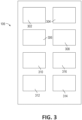
- FIG. 3 is a schematic of the portable measurement device 106.
- the portable measurement device 106 is independent from and freely movable relative to the light units 104.
- a single portable measurement device 106 may be used for a plurality of light units 104.
- the portable measurement device 106 does not necessarily need to travel everywhere that the light units 104 go.
- the portable measurement device 106 may be utilized while the aircraft is on the ground, and then removed from the aircraft before the aircraft is in the air. As such, the portable measurement device 106 does not need to be a flying piece of equipment (although it could be included to change or adjust light units 104 midflight as desired by the customer).
- the portable measurement device 106 includes a sensor 302, a visual display 304, and a communication module 306.
- the portable measurement device 106 may also include a power source 308 and/or a status indicator 310.
- the portable measurement device 106 also includes a controller having a processor 312 and a memory 314.
- the sensor 302 is a light sensor configured to detect various attributes of light.
- the visual display 304 is configured to provide information to the user of the portable measurement device 106.
- the portable measurement device 106 may display the last color that was measured, numeric data of measurements, text messages, or other information to the user through the visual display 304.
- the communication module enables communication between the portable measurement device 106 and the controller 102.
- the communication module 306 includes a communication interface 307 (see FIG. 5 ).
- the power source 308 may include batteries or other suitable power sources.
- the status indicator 310 may be a component of the visual display 304 or may be a separate component. In various cases, the status indicator 310 provides status information about the portable measurement device 106 to the user, including, but not limited to, a ready to measure indication, a not ready to measure indication, a battery low indication, a measurement data okay indication, an error indication, etc.
- the controller may be configured to perform initial analysis of the measured data (e.g., calculate CCT, color coordinates, CRI, etc.).
- the controller includes a processor 312 and a memory 314. The controller may further be configured to control various aspects of the portable measurement device 106. As one non-limiting example, the controller may control when data transmissions are sent between the portable measurement device 106 and the controller 104.
- buttons 316 or other features may be provided such that the user of the portable measurement device 106 can perform various tasks on or with the portable measurement device 106.
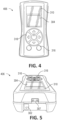
- FIGs. 4 and 5 illustrate another example of a portable measurement device 406 that is substantially similar to the portable measurement device 106.
- FIG. 6 illustrates an example of the lighting system 100 with the reference light unit 105.
- the method includes measuring the light from the light unit 104 of the lighting system 100 with the portable measurement device 106.
- the method includes measuring the light from a plurality of light units 104.
- measuring the light includes measuring at least one attribute of the light, such as an intensity or color of the light, among others.
- the method includes calculating an aspect about the light, such as light intensity, light color, CRI, CCT, color coordinates, etc.
- the method includes transmitting the measured data from the portable measurement device 106 as an output signal to the controller 102.
- controlling the method includes controlling one or more of the light unit 104 based on the measured data.
- controlling the light unit 104 includes adjusting a color or a brightness of the light.
- controlling the light unit 104 includes synchronizing, controlling, and/or adjusting at least two light units 104 based on the measured data.
- controlling the light unit 104 includes comparing the measured data to reference data, and after determining whether there is a difference between the measured data and the reference data in a step 706, adjusting the light emitted from the light unit 104 based on a difference between the measured attribute and the reference data in a step 708.
- controlling and adjusting the light includes comparing the measured data for each light unit to the reference data and adjusting the light emitted from a particular light unit 104 based on a difference between the measured attribute from that light unit 104 and the reference data.
- controlling and adjusting the light includes comparing the measured data from a reference light unit 105 to the reference data and adjusting each light unit 104 based on a difference between the measured data from the reference light unit 105 and the reference data.
- the method includes measuring light from another light unit 104 with the portable measurement device 106 and controlling that light unit 104.
- the next light unit 104 is in the same aircraft cabin, while in other examples the next light unit 104 is in a different aircraft cabin.
Landscapes
- Engineering & Computer Science (AREA)
- Aviation & Aerospace Engineering (AREA)
- Computer Networks & Wireless Communication (AREA)
- Circuit Arrangement For Electric Light Sources In General (AREA)
Description
- This application relates to lighting systems, and more particularly to systems and devices for measuring and controlling light output of a lighting system in an aircraft.
- Lighting systems are used to provide lighting or illumination in various spaces. For example, an aircraft may include a lighting system to provide lighting at various locations throughout the interior of the cabin of the aircraft. As lighting systems age, the light output coming from one or more light units may change due to degradation of color, degradation of light intensity, and various other aging effects. Such effects may result in uneven lighting in the cabin and detract from the experience of the passenger in the cabin. However, typical lighting systems, particularly those used in aircraft, are not able to adapt or adjust their light output after installation.
-
WO 2006/083934 discloses a lighting system comprising a programmer connected to a lighting unit, Lighting information is input into the programmer, and data representing the lighting information is transmitted from the programmer to the lighting unit. -
EP 2960643 discloses a system for monitoring a light transmissive cover of a light. - Particularly, in the words of the cited patent document, it discloses detection means which is configured to check integrity of a light permeable cover on the basis of a field intensity measured by a sensor and reference data indicative of one or more reference conditions of integrity of the cover.
- The terms "invention," "the invention," "this invention" and "the present invention" used in this patent are intended to refer broadly to all of the subject matter of this patent and the patent claims below. Statements containing these terms should be understood not to limit the subject matter described herein or to limit the meaning or scope of the patent claims below. Embodiments of the invention covered by this patent are defined by the claims below, not this summary. This summary is a high-level overview of various embodiments of the invention and introduces some of the concepts that are further described in the Detailed Description section below. This summary is not intended to identify key or essential features of the claimed subject matter, nor is it intended to be used in isolation to determine the scope of the claimed subject matter. The subject matter should be understood by reference to appropriate portions of the entire specification of this patent, any or all drawings, and each claim.
- The disclosure concerns an aircraft lighting system as defined by the features of claim 1.
- In some cases, the portable measurement device includes a sensor, a visual display, and a communication module. In various aspects, the portable measurement device further includes a power source and a status indicator. According to various cases, the at least one attribute of the light emitted from the light unit includes an intensity of the light or a color of the light. In certain aspects, the light unit includes a plurality of light units, where the portable measurement device is configured to measure the at least one attribute of the light emitted from each light unit, and where the control unit is configured to control each light unit based on the measured attribute corresponding to each light unit. In various examples, the control unit is configured to control each light unit such that the at least one attribute of the light emitted from each light unit is the same.
- In various examples, the control unit is configured to control the light unit based on the measured attribute by comparing the at least one measured attribute to a predetermined attribute and controlling the light emitted from the light unit such that the measured attribute matches the predetermined attribute. According to some examples, the control unit is further configured to determine the predetermined attribute by receiving a reference signal from the portable measurement device, where the reference signal includes the predetermined attribute measured by the portable measurement device from a reference light unit.
- In certain aspects, the light unit includes a plurality of light units, and the plurality of light units including at least one reference light unit. In various cases, the portable measurement device is configured to measure the at least one attribute of the light emitted from the reference light unit, and the control unit is configured to control each light unit based on the measured attribute from the reference light unit. In various aspects, one of the plurality of light units includes a first type of light source and another of the plurality of light units includes a second type of light source different from the first type of light source. In some examples, the light unit includes a unique identifier, and the portable measurement device is configured to receive the unique identifier before measuring the at least one attribute of the light emitted from the light unit and output the measured attribute of the light with the unique identifier in the output signal.
- The disclosure concerns a method defined by the features of claim 8.
- In various examples, the light unit includes a plurality of light units, and the plurality of light units includes a reference light unit. In some aspects, measuring includes measuring the at least one attribute of light of the reference light unit, and controlling includes controlling the plurality of light units based on the measured attribute from the reference light unit. According to certain examples, controlling includes controlling each light unit such that the at least one attribute of the light emitted from each light unit is the same.
- In certain aspects, the light unit includes a plurality of light units, measuring includes measuring the at least one attribute of light of each of the plurality of light units, and controlling includes controlling each of the plurality of light units based on the measured attribute from that light unit. According to various examples, controlling includes controlling each light unit such that the at least one attribute of the light emitted from each light unit is the same.
- In certain cases, measuring includes measuring at least one of an intensity of the light or a color of the light. In some aspects, controlling includes comparing the measured attribute to reference data and adjusting the light emitted from the light unit based on a difference between the measured attribute and the reference data. In various cases, the method includes displaying a last color measured on the portable measurement device. In certain examples, the method includes measuring a color of an illuminated surface with the portable measurement device, and controlling the light unit such that a color of the light emitted from the light unit matches the color of the illuminated surface.
- Various implementations described in the present disclosure can include additional systems, methods, features, and advantages, which cannot necessarily be expressly disclosed herein but will be apparent to one of ordinary skill in the art upon examination of the following detailed description and accompanying drawings. It is intended that all such systems, methods, features, and advantages be included within the present disclosure and protected by the accompanying claims.
- The features and components of the following figures are illustrated to emphasize the general principles of the present disclosure. Corresponding features and components throughout the figures can be designated by matching reference characters for the sake of consistency and clarity.
-
FIG. 1 is a schematic of a lighting system according to aspects of the current disclosure. -
FIG. 2 is a schematic of the lighting system ofFIG. 1 with a handheld measurement device according to aspects of the current disclosure. -
FIG. 3 is a schematic of the handheld measurement device ofFIG. 2 according to aspects of the current disclosure. -
FIG. 4 is a front view of a handheld measurement device according to aspects of the current disclosure. -
FIG. 5 is a perspective view of the handheld measurement device ofFIG. 4 . -
FIG. 6 is a schematic of a lighting system with a handheld measurement device according to aspects of the current disclosure. -
FIG. 7 is a flowchart of steps of method of controlling a lighting system according to aspects of the current disclosure. - The subject matter of embodiments of the present invention is described here with specificity to meet statutory requirements, but this description is not necessarily intended to limit the scope of the claims. The claimed subject matter may be embodied in other ways, may include different elements or steps, and may be used in conjunction with other existing or future technologies. This description should not be interpreted as implying any particular order or arrangement among or between various steps or elements except when the order of individual steps or arrangement of elements is explicitly described. Directional references such as "up," "down," "top," "left," "right," "front," and "back," among others, are intended to refer to the orientation as illustrated and described in the figure (or figures) to which the components and directions are referencing. References herein to "consisting of" may, in at least some circumstances, encompass "consisting essentially of" or "comprising."
- In some aspects, disclosed is a lighting system, including, but not limited to, a lighting system used in aircraft. The lighting system includes a portable measurement device that is independent from and freely movable relative to light units of the aircraft (or other environment). In some aspects, the portable measurement device includes a light sensor, a communication module, and a visual display. In certain cases, the portable measurement device includes a power source and a status indicator. In some aspects, the portable measurement device includes control buttons. The portable measurement device is configured to measure at least one attribute of the light emitted from a light unit with the sensor. In certain cases, the portable measurement device is configured to detect a color and/or a light intensity of the light. In certain examples, based on the measured data, the portable measuring device can calculate different attributes of the light, including, but not limited to, color rendering index (CRI), correlated color temperature (CCT), color coordinates, etc. The portable measurement device is further configured to output the measured attribute in an output signal, and transfer the output signal to a control unit of the lighting system. Optionally, the portable measurement device is configured to display a last color that was measured, provide status information about the portable measurement device, provide numeric data of measurements, provide text messages to the user, and/or provide various other features as desired.
- The control unit of the lighting system receives the output signal from the portable measurement device, which includes the measured attribute data, and controls the light unit based on the measured attribute data (and/or based on the attribute data determined by the portable measurement device based on the measured attribute data). In some cases, the controller compares the measured attribute data with reference data (which may be stored in the system) to detect deviations from predetermined light color and/or light intensity values, among others. In various examples, the control unit controls the light units such that one or more light units are synchronized. In certain cases, the control unit controls the light units such that one or more light units are adjusted.
- The lighting system includes at least one light unit configured to emit light, and in many examples includes a plurality of light units. In some examples, the light units are LED light units, although they need not be. The light units may be various types of light sources. For example, the light units may be strip light units, dome light units, spot light units, or various other types of light sources. As some non-limiting examples, in an aircraft cabin, different light units optionally include spot light units for the passenger seats, strip light units for ceiling and sidewalls, dome light units for the galley and entry threshold, etc. In other examples, different light units may be provided in different parts of the aircraft cabin.
- In some examples, with the lighting system, the light unit and system settings can be adjusted as desired. For example, the light unit and system settings may be adjusted during aircraft maintenance, by flight attendants during travel, etc. The light unit and system settings can be adjusted by using the portable measurement device such that light settings can be changed, adapted, and synchronized according to customer needs at any time. In some examples, the customers (e.g., airlines or other aircraft operators) may change the lighting system parameters to achieve a fleet-wide commonality of output (e.g., with airline brand colors), even if the customer has different aircraft models with cabin interiors and light units of different states and ages.
-
FIGs. 1 and 2 are schematics of alighting system 100 according to aspects of the current disclosure. Thelighting system 100 is in the cabin of an aircraft. Thelighting system 100 includes acontroller 102, and in certain aspects may include a plurality of controllers. In some examples, thecontroller 102 is an independent component; however, in other examples, thecontroller 102 may be a component of a light unit 104 (i.e., one or more light units 104 may include a controller on the light unit 104 itself). - The
controller 102 is coupled to one or more light units 104. In the example ofFIGs. 1 and 2 , thecontroller 102 is communicatively connected to fourlight units 104A-D. Thecontroller 102 may be connected to the light units 104 through various suitable mechanisms including, but not limited wireless communication, wired communication, Bluetooth, WiFi, infrared communication, etc. In some optional examples, thecontroller 102 is connected to the same type of light unit 104 (e.g., all of the light units are strip lights, dome lights, spot lights, etc.). In other optional examples, thecontroller 102 is connected to at least two different types of light units 104. In the example ofFIGs. 1 and 2 , thelight units 104A-C are a first type of light unit (e.g., a spot light unit) and thelight unit 104D is a second type of light unit different from the first type of light unit (e.g., a dome light unit). - A
portable measurement device 106 is also provided with thelighting system 100. Theportable measurement device 106 is independent from and freely movable relative to the light units 104. In various aspects, theportable measurement device 106 includes at least one sensor such that theportable measurement device 106 can detect the light emitted by at least one of the light units 104. In some examples, theportable measurement device 106 detects the light emitted by more than one light unit 104 (e.g., bylight unit Figure 2 ); however, in other examples, one of the light units 104 (e.g.,light unit 104A) is areference light unit 105, and theportable measurement device 106 detects the light emitted by the reference light unit 105 (see, e.g.,FIG. 6 ). In certain aspects, theportable measurement device 106 is configured to measure at least one attribute of the light, including, but not limited to, light intensity, light color, CRI, CCT, color coordinates, etc. - In certain examples, after detecting the light, the
portable measurement device 106 transfers the measured data to thecontroller 102. In some optional examples, theportable measurement device 106 may store the measured data for later transfer and/or documentation. The data transfer between theportable measurement device 106 and thecontroller 102 may include various suitable communication mechanisms including, but not limited to, a wired connection, wireless connection, Bluetooth, WiFi, infrared communication, etc. - Based on the measured data, the
controller 102 controls the light units 104. In some examples, thecontroller 102 controls the light units 104 by sending control data to each light unit 104. The control data may include at least color and brightness information. In various examples, thecontroller 102 compares the measured data with reference data to detect deviations from predetermined light color and/or intensity values. In various examples, the reference data may include data from a reference light unit or predetermined data (e.g., predetermined color and/or brightness). In some examples, the light units 104 are controlled such that at least two light units 104 are set to be the same color as the reference light unit. In other examples, the light units 104 are controlled such that at least two light units 104 are set to the same light intensity and/or brightness. In certain cases, the light units 104 are controlled such that the light units 104 have a predetermined pattern of color and/or brightness. In some examples, theportable measurement device 106 measures the light as it is actually perceived and the light units 104 are controlled as the light is actually perceived rather than as the light is emitted, although it need not. - In various examples, the measured data includes a unique identifier. In some non-limiting examples, the unique identifier includes an identification number. In various examples, before taking the measurement, the
portable measurement device 106 determines the identification number (or other unique identifier), and then transmits the unique identifier to the controller with the measured data. In some examples, the unique identifier is a light signal emitted by the light unit 104. -
FIG. 3 is a schematic of theportable measurement device 106. Theportable measurement device 106 is independent from and freely movable relative to the light units 104. In certain aspects, a singleportable measurement device 106 may be used for a plurality of light units 104. In addition, theportable measurement device 106 does not necessarily need to travel everywhere that the light units 104 go. As one non-limiting example, in an aircraft, theportable measurement device 106 may be utilized while the aircraft is on the ground, and then removed from the aircraft before the aircraft is in the air. As such, theportable measurement device 106 does not need to be a flying piece of equipment (although it could be included to change or adjust light units 104 midflight as desired by the customer). - As illustrated, the
portable measurement device 106 includes asensor 302, avisual display 304, and acommunication module 306. Theportable measurement device 106 may also include apower source 308 and/or astatus indicator 310. Theportable measurement device 106 also includes a controller having aprocessor 312 and amemory 314. In some examples, thesensor 302 is a light sensor configured to detect various attributes of light. In various examples, thevisual display 304 is configured to provide information to the user of theportable measurement device 106. For example, in some non-limiting cases, theportable measurement device 106 may display the last color that was measured, numeric data of measurements, text messages, or other information to the user through thevisual display 304. In some cases, the communication module enables communication between theportable measurement device 106 and thecontroller 102. Optionally, thecommunication module 306 includes a communication interface 307 (seeFIG. 5 ). In various aspects, thepower source 308 may include batteries or other suitable power sources. - In certain aspects, the
status indicator 310 may be a component of thevisual display 304 or may be a separate component. In various cases, thestatus indicator 310 provides status information about theportable measurement device 106 to the user, including, but not limited to, a ready to measure indication, a not ready to measure indication, a battery low indication, a measurement data okay indication, an error indication, etc. The controller may be configured to perform initial analysis of the measured data (e.g., calculate CCT, color coordinates, CRI, etc.). In various aspects, the controller includes aprocessor 312 and amemory 314. The controller may further be configured to control various aspects of theportable measurement device 106. As one non-limiting example, the controller may control when data transmissions are sent between theportable measurement device 106 and the controller 104. Optionally,buttons 316 or other features (e.g., a keypad or other input device) may be provided such that the user of theportable measurement device 106 can perform various tasks on or with theportable measurement device 106. -
FIGs. 4 and 5 illustrate another example of aportable measurement device 406 that is substantially similar to theportable measurement device 106.FIG. 6 illustrates an example of thelighting system 100 with thereference light unit 105. - Referring to
FIG. 7 , a non-limiting example of a method of controlling a light unit 104 is also provided. In some examples, in astep 702, the method includes measuring the light from the light unit 104 of thelighting system 100 with theportable measurement device 106. In various examples, the method includes measuring the light from a plurality of light units 104. In certain cases, measuring the light includes measuring at least one attribute of the light, such as an intensity or color of the light, among others. Optionally, the method includes calculating an aspect about the light, such as light intensity, light color, CRI, CCT, color coordinates, etc. The method includes transmitting the measured data from theportable measurement device 106 as an output signal to thecontroller 102. - In some examples, the method includes controlling one or more of the light unit 104 based on the measured data. In certain examples, controlling the light unit 104 includes adjusting a color or a brightness of the light. In various examples, controlling the light unit 104 includes synchronizing, controlling, and/or adjusting at least two light units 104 based on the measured data. In various cases, in a
step 704, controlling the light unit 104 includes comparing the measured data to reference data, and after determining whether there is a difference between the measured data and the reference data in astep 706, adjusting the light emitted from the light unit 104 based on a difference between the measured attribute and the reference data in astep 708. Optionally, in astep 710, it is determined whether other light units 104 in thelighting system 100 need to be checked for controlling, synchronizing, and/or adjusting. In some cases with a plurality of light units 104, controlling and adjusting the light includes comparing the measured data for each light unit to the reference data and adjusting the light emitted from a particular light unit 104 based on a difference between the measured attribute from that light unit 104 and the reference data. With a plurality of light units 104, controlling and adjusting the light includes comparing the measured data from areference light unit 105 to the reference data and adjusting each light unit 104 based on a difference between the measured data from thereference light unit 105 and the reference data. In various examples, the method includes measuring light from another light unit 104 with theportable measurement device 106 and controlling that light unit 104. In some examples, the next light unit 104 is in the same aircraft cabin, while in other examples the next light unit 104 is in a different aircraft cabin. - The above-described aspects are merely possible examples of implementations, merely set forth for a clear understanding of the principles of the present disclosure. Many variations and modifications can be made to the above-described embodiment(s) without departing substantially from the spirit and principles of the present disclosure. All such modifications and variations are intended to be included herein within the scope of the present disclosure, and all possible claims to individual aspects or combinations of elements or steps are intended to be supported by the present disclosure. Moreover, although specific terms are employed herein, as well as in the claims that follow, they are used only in a generic and descriptive sense, and not for the purposes of limiting the described invention, nor the claims that follow.
Claims (13)
- An aircraft lighting system (100) comprising:a light unit (104, 104A, 104B, 104D) positionable in an aircraft and configured to emit light;a portable and handheld measurement device (106, 406) independent from and freely movable relative to the light units (104), the portable and handheld measurement device (106, 406) comprising a sensor (302), a communication module (306), a visual display (304) on the portable and handheld measurement device (106, 406), and a controller having a processor (312) and memory (314), wherein the portable and handheld measurement device (106, 406) is configured to measure at least one attribute of the light emitted from the light unit (104, 104A, 104B, 104D) and output the measured attribute of the light in an output signal; anda control unit (102) connected to the light unit (104, 104A, 104B, 104D) via wireless communication and configured to receive the output signal and control the light unit (104, 104A, 104B, 104D) based on the measured attribute; andwherein, when the control unit (102) receives the measured attribute, the control unit (102) compares the measured attribute to reference data and adjusts the light emitted from the light unit (104, 104A, 104B, 104D) based on a difference between the measured attribute and the reference data.
- The aircraft lighting system (100) according to claim 1, wherein the portable measurement device (106, 406) further comprises a power source (308) and a status indicator (310).
- The aircraft lighting system (100) according to any of claims 1 and 2, wherein the at least one attribute of the light emitted from the light unit (104, 104A, 104B, 104D) comprises an intensity of the light or a color of the light.
- The aircraft lighting system (100) according to any of claims 1 to 3, wherein the light unit (104, 104A, 104B, 104D) comprises a plurality of light units (104, 104A, 104B, 104D), wherein the portable measurement device (106, 406) is configured to measure the at least one attribute of the light emitted from at least one of the plurality of light units (104, 104A, 104B, 104D), and wherein the control unit is configured to control each light unit (104, 104A, 104B, 104D) of the plurality of light units (104, 104A, 104B, 104D) based on the measured attribute.
- The aircraft lighting system (100) according to claim 4, wherein the control unit is configured to control each light unit (104, 104A, 104B, 104D) of the plurality of light units (104, 104A, 104B, 104D) such that the at least one attribute of the light emitted from each light unit (104, 104A, 104B, 104D) of the plurality of light units (104, 104A, 104B, 104D) is the same.
- The aircraft lighting system (100) according to claim 4, wherein one of the plurality of light unit (104, 104A, 104B, 104D)s is a reference light unit (105), wherein the portable measurement device (106, 406) is configured to measure the at least one attribute of the light emitted from the reference light unit (105), and wherein the control unit is configured to control each light unit (104, 104A, 104B, 104D) of the plurality of light unit (104, 104A, 104B, 104D)s based on the measured attribute from the reference light unit (105).
- The aircraft lighting system (100) according to claim 4, wherein one of the plurality of light unit (104, 104A, 104B, 104D)s comprises a first type of light source and another of the plurality of light unit (104, 104A, 104B, 104D)s comprises a second type of light source different from the first type of light source.
- A method of controlling a lighting system (100) comprising:measuring at least one attribute of light of a light unit (104, 104A, 104B, 104D) in an aircraft with a portable and handheld measurement device, the portable and handheld measurement device (106, 406) independent from and freely movable relative to the light unit (104, 104A, 104B, 104D), wherein the portable and handheld measurement device comprises a sensor (302), a communication module (306), a visual display (304) on the portable and handheld measurement device, and a controller having a processor (312) and memory (314),;transmitting the measured attribute via wireless communication to a control unit;comparing the measured attribute to reference data; andadjusting the light emitted from the light unit (104, 104A, 104B, 104D) based on a difference between the measured attribute and the reference data.
- The method of claim 8, wherein the light unit (104, 104A, 104B, 104D) comprises a plurality of light unit (104, 104A, 104B, 104D)s, the plurality of light unit (104, 104A, 104B, 104D)s comprising a reference light unit (105),wherein measuring comprises measuring the at least one attribute of light of each of the reference light unit (105) and one or more of the plurality of light unit (104, 104A, 104B, 104D),wherein the at least one attribute of light of the reference unit is the reference data and the at least one attribute of the one or more plurality of light unit (104, 104A, 104B, 104D) is the measured attribute,and wherein adjusting comprises adjusting the one or more of the plurality of light unit (104, 104A, 104B, 104D)s based on a difference between the measured attribute and the reference data.
- The method of claim 9, wherein adjusting further comprises adjusting each light unit (104, 104A, 104B, 104D) of the plurality of light unit (104, 104A, 104B, 104D)s such that the at least one attribute of light emitted from each light unit (104, 104A, 104B, 104D) of the plurality of light unit (104, 104A, 104B, 104D)s is the same.
- The method of claim 8, wherein the light unit (104, 104A, 104B, 104D) comprises a plurality of light unit (104, 104A, 104B, 104D)s, wherein measuring comprises measuring the at least one attribute of light of each of the plurality of light unit (104, 104A, 104B, 104D)s, wherein comparing comprises comparing the measured attribute of each of the plurality of light unit (104, 104A, 104B, 104D)s to the reference data, and wherein adjusting comprises adjusting each of the plurality of light unit (104, 104A, 104B, 104D)s based on a difference between the measured attribute and the reference data.
- The method of claim 8, wherein measuring comprises measuring at least one of an intensity of the light or a color of the light.
- The method of claim 8, further comprising measuring a color of an illuminated surface with the portable measurement device (106, 406), and controlling the light unit (104, 104A, 104B, 104D) such that a color of the light emitted from the light unit (104, 104A, 104B, 104D) matches the color of the illuminated surface.
Applications Claiming Priority (2)
| Application Number | Priority Date | Filing Date | Title |
|---|---|---|---|
| US201762478328P | 2017-03-29 | 2017-03-29 | |
| PCT/IB2018/052156 WO2018178908A1 (en) | 2017-03-29 | 2018-03-29 | Aircraft lighting systems and methods |
Publications (2)
| Publication Number | Publication Date |
|---|---|
| EP3601059A1 EP3601059A1 (en) | 2020-02-05 |
| EP3601059B1 true EP3601059B1 (en) | 2025-03-12 |
Family
ID=62028067
Family Applications (1)
| Application Number | Title | Priority Date | Filing Date |
|---|---|---|---|
| EP18719293.5A Active EP3601059B1 (en) | 2017-03-29 | 2018-03-29 | Aircraft lighting systems and methods |
Country Status (3)
| Country | Link |
|---|---|
| US (1) | US11142338B2 (en) |
| EP (1) | EP3601059B1 (en) |
| WO (1) | WO2018178908A1 (en) |
Families Citing this family (3)
| Publication number | Priority date | Publication date | Assignee | Title |
|---|---|---|---|---|
| GB2577852A (en) * | 2018-06-14 | 2020-04-15 | Saf T Glo Ltd | Lighting systems |
| EP3813488A4 (en) * | 2018-06-19 | 2022-02-23 | Iris Communication Kabushiki Kaisha | LIGHTING CONTROL SYSTEM, LIGHTING CONTROL METHOD AND LIGHTING CONTROL PROGRAM |
| US11019691B1 (en) | 2020-01-17 | 2021-05-25 | B/E Aerospace, Inc. | Galley insert multi-purpose LED system |
Family Cites Families (7)
| Publication number | Priority date | Publication date | Assignee | Title |
|---|---|---|---|---|
| US7014336B1 (en) * | 1999-11-18 | 2006-03-21 | Color Kinetics Incorporated | Systems and methods for generating and modulating illumination conditions |
| US20050174473A1 (en) * | 1999-11-18 | 2005-08-11 | Color Kinetics, Inc. | Photography methods and systems |
| DE60330967D1 (en) * | 2002-08-28 | 2010-03-04 | Philips Solid State Lighting | METHOD AND SYSTEMS FOR LIGHTING ENVIRONMENTS |
| WO2006083934A2 (en) * | 2005-02-01 | 2006-08-10 | B/E Aerospace, Inc. | Lighting system and method and apparatus for adjusting same |
| US9061772B1 (en) * | 2012-06-11 | 2015-06-23 | The Boeing Company | Dual mode lights automatic intensity control |
| US9650141B2 (en) | 2013-01-31 | 2017-05-16 | Bombardier Inc. | System and a method of operation of the system incorporating a graphical user interface in a bulkhead of a vehicle cabin |
| EP2960643B1 (en) * | 2014-06-27 | 2019-03-13 | Leonardo S.p.A. | System for monitoring a light transparent cover of a light or lamp, especially of an aircraft's external light |
-
2018
- 2018-03-29 WO PCT/IB2018/052156 patent/WO2018178908A1/en not_active Ceased
- 2018-03-29 EP EP18719293.5A patent/EP3601059B1/en active Active
- 2018-03-29 US US16/498,608 patent/US11142338B2/en active Active
Also Published As
| Publication number | Publication date |
|---|---|
| EP3601059A1 (en) | 2020-02-05 |
| US20200102092A1 (en) | 2020-04-02 |
| WO2018178908A1 (en) | 2018-10-04 |
| US11142338B2 (en) | 2021-10-12 |
Similar Documents
| Publication | Publication Date | Title |
|---|---|---|
| US11482061B2 (en) | Vehicle readiness system | |
| US8930088B2 (en) | Method for positioning at least one component, in particular a seat, in or on an aircraft or spacecraft, and aircraft or spacecraft | |
| EP3297917B1 (en) | Airflow management in cabin of aircraft | |
| US11142338B2 (en) | Aircraft lighting systems and methods | |
| EP2871079B1 (en) | Tire inflate/deflate indication method and system | |
| CN106482060B (en) | Aircraft exterior lighting device | |
| KR20190073299A (en) | Tyre monitoring device and method | |
| KR101624867B1 (en) | System and method for monitoring condition and acting using LED lights with sensor | |
| CN101788342A (en) | Color calibration system | |
| CN113260522A (en) | Validation of tire monitoring device status | |
| JP6774983B2 (en) | Safety system for processes with a work area on the opposite side of the barrier as seen from the equipment | |
| WO2014123593A1 (en) | Flight deck lighting for information display | |
| KR20100092246A (en) | Firesafe induce system including emergency exit guide lamp using low power wireless sensors | |
| US20140055040A1 (en) | Lighting control system | |
| US10043363B2 (en) | System and a method for detecting low concentrations of specific chemical compounds in the air of an aircraft cabin | |
| CN105588693A (en) | Bleed air duct leak system real-time fault detection | |
| US20160381439A1 (en) | Indoor environment management apparatus, indoor environment control system, and computer-readable recording medium | |
| US9061772B1 (en) | Dual mode lights automatic intensity control | |
| US9035801B2 (en) | Flight deck lighting for information display | |
| US20230412214A1 (en) | Aircraft passenger service unit, aircraft passenger service unit assembly, and method of determining spatial positions and/or orientations of a plurality of aircraft passenger service units | |
| KR20170045825A (en) | traffic signal indicator system of inner tunnel | |
| KR101846495B1 (en) | Method for controlling and operating LED lighting for saving energy based on wireless network | |
| JP2021152937A (en) | Disaster prevention system | |
| EP3130200B1 (en) | Wireless configuration and diagnostics of airfield lighting fixtures | |
| CN113226806A (en) | Indicating errors in a tire monitoring system |
Legal Events
| Date | Code | Title | Description |
|---|---|---|---|
| STAA | Information on the status of an ep patent application or granted ep patent |
Free format text: STATUS: UNKNOWN |
|
| STAA | Information on the status of an ep patent application or granted ep patent |
Free format text: STATUS: THE INTERNATIONAL PUBLICATION HAS BEEN MADE |
|
| PUAI | Public reference made under article 153(3) epc to a published international application that has entered the european phase |
Free format text: ORIGINAL CODE: 0009012 |
|
| STAA | Information on the status of an ep patent application or granted ep patent |
Free format text: STATUS: REQUEST FOR EXAMINATION WAS MADE |
|
| 17P | Request for examination filed |
Effective date: 20191024 |
|
| AK | Designated contracting states |
Kind code of ref document: A1 Designated state(s): AL AT BE BG CH CY CZ DE DK EE ES FI FR GB GR HR HU IE IS IT LI LT LU LV MC MK MT NL NO PL PT RO RS SE SI SK SM TR |
|
| AX | Request for extension of the european patent |
Extension state: BA ME |
|
| DAV | Request for validation of the european patent (deleted) | ||
| DAX | Request for extension of the european patent (deleted) | ||
| STAA | Information on the status of an ep patent application or granted ep patent |
Free format text: STATUS: EXAMINATION IS IN PROGRESS |
|
| 17Q | First examination report despatched |
Effective date: 20210309 |
|
| GRAP | Despatch of communication of intention to grant a patent |
Free format text: ORIGINAL CODE: EPIDOSNIGR1 |
|
| STAA | Information on the status of an ep patent application or granted ep patent |
Free format text: STATUS: GRANT OF PATENT IS INTENDED |
|
| RIC1 | Information provided on ipc code assigned before grant |
Ipc: B64D 11/00 20060101ALI20240926BHEP Ipc: B64D 47/02 20060101AFI20240926BHEP |
|
| INTG | Intention to grant announced |
Effective date: 20241011 |
|
| GRAS | Grant fee paid |
Free format text: ORIGINAL CODE: EPIDOSNIGR3 |
|
| GRAA | (expected) grant |
Free format text: ORIGINAL CODE: 0009210 |
|
| STAA | Information on the status of an ep patent application or granted ep patent |
Free format text: STATUS: THE PATENT HAS BEEN GRANTED |
|
| AK | Designated contracting states |
Kind code of ref document: B1 Designated state(s): AL AT BE BG CH CY CZ DE DK EE ES FI FR GB GR HR HU IE IS IT LI LT LU LV MC MK MT NL NO PL PT RO RS SE SI SK SM TR |
|
| REG | Reference to a national code |
Ref country code: GB Ref legal event code: FG4D |
|
| REG | Reference to a national code |
Ref country code: CH Ref legal event code: EP |
|
| REG | Reference to a national code |
Ref country code: DE Ref legal event code: R096 Ref document number: 602018080026 Country of ref document: DE |
|
| REG | Reference to a national code |
Ref country code: IE Ref legal event code: FG4D |
|
| PG25 | Lapsed in a contracting state [announced via postgrant information from national office to epo] |
Ref country code: RS Free format text: LAPSE BECAUSE OF FAILURE TO SUBMIT A TRANSLATION OF THE DESCRIPTION OR TO PAY THE FEE WITHIN THE PRESCRIBED TIME-LIMIT Effective date: 20250612 |
|
| PG25 | Lapsed in a contracting state [announced via postgrant information from national office to epo] |
Ref country code: FI Free format text: LAPSE BECAUSE OF FAILURE TO SUBMIT A TRANSLATION OF THE DESCRIPTION OR TO PAY THE FEE WITHIN THE PRESCRIBED TIME-LIMIT Effective date: 20250312 |
|
| PG25 | Lapsed in a contracting state [announced via postgrant information from national office to epo] |
Ref country code: ES Free format text: LAPSE BECAUSE OF FAILURE TO SUBMIT A TRANSLATION OF THE DESCRIPTION OR TO PAY THE FEE WITHIN THE PRESCRIBED TIME-LIMIT Effective date: 20250312 |
|
| REG | Reference to a national code |
Ref country code: LT Ref legal event code: MG9D |
|
| PG25 | Lapsed in a contracting state [announced via postgrant information from national office to epo] |
Ref country code: NO Free format text: LAPSE BECAUSE OF FAILURE TO SUBMIT A TRANSLATION OF THE DESCRIPTION OR TO PAY THE FEE WITHIN THE PRESCRIBED TIME-LIMIT Effective date: 20250612 |
|
| PG25 | Lapsed in a contracting state [announced via postgrant information from national office to epo] |
Ref country code: HR Free format text: LAPSE BECAUSE OF FAILURE TO SUBMIT A TRANSLATION OF THE DESCRIPTION OR TO PAY THE FEE WITHIN THE PRESCRIBED TIME-LIMIT Effective date: 20250312 |
|
| REG | Reference to a national code |
Ref country code: NL Ref legal event code: MP Effective date: 20250312 |
|
| PG25 | Lapsed in a contracting state [announced via postgrant information from national office to epo] |
Ref country code: LV Free format text: LAPSE BECAUSE OF FAILURE TO SUBMIT A TRANSLATION OF THE DESCRIPTION OR TO PAY THE FEE WITHIN THE PRESCRIBED TIME-LIMIT Effective date: 20250312 |
|
| PG25 | Lapsed in a contracting state [announced via postgrant information from national office to epo] |
Ref country code: GR Free format text: LAPSE BECAUSE OF FAILURE TO SUBMIT A TRANSLATION OF THE DESCRIPTION OR TO PAY THE FEE WITHIN THE PRESCRIBED TIME-LIMIT Effective date: 20250613 Ref country code: BG Free format text: LAPSE BECAUSE OF FAILURE TO SUBMIT A TRANSLATION OF THE DESCRIPTION OR TO PAY THE FEE WITHIN THE PRESCRIBED TIME-LIMIT Effective date: 20250312 |
|
| REG | Reference to a national code |
Ref country code: AT Ref legal event code: MK05 Ref document number: 1774860 Country of ref document: AT Kind code of ref document: T Effective date: 20250312 |
|
| PG25 | Lapsed in a contracting state [announced via postgrant information from national office to epo] |
Ref country code: NL Free format text: LAPSE BECAUSE OF FAILURE TO SUBMIT A TRANSLATION OF THE DESCRIPTION OR TO PAY THE FEE WITHIN THE PRESCRIBED TIME-LIMIT Effective date: 20250312 |
|
| PG25 | Lapsed in a contracting state [announced via postgrant information from national office to epo] |
Ref country code: SE Free format text: LAPSE BECAUSE OF FAILURE TO SUBMIT A TRANSLATION OF THE DESCRIPTION OR TO PAY THE FEE WITHIN THE PRESCRIBED TIME-LIMIT Effective date: 20250312 |
|
| PG25 | Lapsed in a contracting state [announced via postgrant information from national office to epo] |
Ref country code: SM Free format text: LAPSE BECAUSE OF FAILURE TO SUBMIT A TRANSLATION OF THE DESCRIPTION OR TO PAY THE FEE WITHIN THE PRESCRIBED TIME-LIMIT Effective date: 20250312 |
|
| PG25 | Lapsed in a contracting state [announced via postgrant information from national office to epo] |
Ref country code: PT Free format text: LAPSE BECAUSE OF FAILURE TO SUBMIT A TRANSLATION OF THE DESCRIPTION OR TO PAY THE FEE WITHIN THE PRESCRIBED TIME-LIMIT Effective date: 20250714 |
|
| PG25 | Lapsed in a contracting state [announced via postgrant information from national office to epo] |
Ref country code: PL Free format text: LAPSE BECAUSE OF FAILURE TO SUBMIT A TRANSLATION OF THE DESCRIPTION OR TO PAY THE FEE WITHIN THE PRESCRIBED TIME-LIMIT Effective date: 20250312 Ref country code: IT Free format text: LAPSE BECAUSE OF FAILURE TO SUBMIT A TRANSLATION OF THE DESCRIPTION OR TO PAY THE FEE WITHIN THE PRESCRIBED TIME-LIMIT Effective date: 20250312 |
|
| PG25 | Lapsed in a contracting state [announced via postgrant information from national office to epo] |
Ref country code: AT Free format text: LAPSE BECAUSE OF FAILURE TO SUBMIT A TRANSLATION OF THE DESCRIPTION OR TO PAY THE FEE WITHIN THE PRESCRIBED TIME-LIMIT Effective date: 20250312 |
|
| PG25 | Lapsed in a contracting state [announced via postgrant information from national office to epo] |
Ref country code: CZ Free format text: LAPSE BECAUSE OF FAILURE TO SUBMIT A TRANSLATION OF THE DESCRIPTION OR TO PAY THE FEE WITHIN THE PRESCRIBED TIME-LIMIT Effective date: 20250312 Ref country code: EE Free format text: LAPSE BECAUSE OF FAILURE TO SUBMIT A TRANSLATION OF THE DESCRIPTION OR TO PAY THE FEE WITHIN THE PRESCRIBED TIME-LIMIT Effective date: 20250312 |
|
| PG25 | Lapsed in a contracting state [announced via postgrant information from national office to epo] |
Ref country code: RO Free format text: LAPSE BECAUSE OF FAILURE TO SUBMIT A TRANSLATION OF THE DESCRIPTION OR TO PAY THE FEE WITHIN THE PRESCRIBED TIME-LIMIT Effective date: 20250312 |
|
| REG | Reference to a national code |
Ref country code: CH Ref legal event code: H13 Free format text: ST27 STATUS EVENT CODE: U-0-0-H10-H13 (AS PROVIDED BY THE NATIONAL OFFICE) Effective date: 20251023 |
|
| PG25 | Lapsed in a contracting state [announced via postgrant information from national office to epo] |
Ref country code: SK Free format text: LAPSE BECAUSE OF FAILURE TO SUBMIT A TRANSLATION OF THE DESCRIPTION OR TO PAY THE FEE WITHIN THE PRESCRIBED TIME-LIMIT Effective date: 20250312 |
|
| PG25 | Lapsed in a contracting state [announced via postgrant information from national office to epo] |
Ref country code: IS Free format text: LAPSE BECAUSE OF FAILURE TO SUBMIT A TRANSLATION OF THE DESCRIPTION OR TO PAY THE FEE WITHIN THE PRESCRIBED TIME-LIMIT Effective date: 20250712 |
|
| PG25 | Lapsed in a contracting state [announced via postgrant information from national office to epo] |
Ref country code: LU Free format text: LAPSE BECAUSE OF NON-PAYMENT OF DUE FEES Effective date: 20250329 |
|
| REG | Reference to a national code |
Ref country code: BE Ref legal event code: MM Effective date: 20250331 |
|
| REG | Reference to a national code |
Ref country code: DE Ref legal event code: R097 Ref document number: 602018080026 Country of ref document: DE |
|
| PG25 | Lapsed in a contracting state [announced via postgrant information from national office to epo] |
Ref country code: MC Free format text: LAPSE BECAUSE OF FAILURE TO SUBMIT A TRANSLATION OF THE DESCRIPTION OR TO PAY THE FEE WITHIN THE PRESCRIBED TIME-LIMIT Effective date: 20250312 |
|
| PG25 | Lapsed in a contracting state [announced via postgrant information from national office to epo] |
Ref country code: DK Free format text: LAPSE BECAUSE OF FAILURE TO SUBMIT A TRANSLATION OF THE DESCRIPTION OR TO PAY THE FEE WITHIN THE PRESCRIBED TIME-LIMIT Effective date: 20250312 |
|
| PG25 | Lapsed in a contracting state [announced via postgrant information from national office to epo] |
Ref country code: BE Free format text: LAPSE BECAUSE OF NON-PAYMENT OF DUE FEES Effective date: 20250331 |
|
| PLBE | No opposition filed within time limit |
Free format text: ORIGINAL CODE: 0009261 |
|
| STAA | Information on the status of an ep patent application or granted ep patent |
Free format text: STATUS: NO OPPOSITION FILED WITHIN TIME LIMIT |
|
| PG25 | Lapsed in a contracting state [announced via postgrant information from national office to epo] |
Ref country code: CH Free format text: LAPSE BECAUSE OF NON-PAYMENT OF DUE FEES Effective date: 20250331 |
|
| PG25 | Lapsed in a contracting state [announced via postgrant information from national office to epo] |
Ref country code: IE Free format text: LAPSE BECAUSE OF NON-PAYMENT OF DUE FEES Effective date: 20250329 |
|
| REG | Reference to a national code |
Ref country code: CH Ref legal event code: L10 Free format text: ST27 STATUS EVENT CODE: U-0-0-L10-L00 (AS PROVIDED BY THE NATIONAL OFFICE) Effective date: 20260121 |
|
| 26N | No opposition filed |
Effective date: 20251215 |
|
| PGFP | Annual fee paid to national office [announced via postgrant information from national office to epo] |
Ref country code: GB Payment date: 20260324 Year of fee payment: 9 |
|
| PGFP | Annual fee paid to national office [announced via postgrant information from national office to epo] |
Ref country code: DE Payment date: 20260320 Year of fee payment: 9 |
|
| PGFP | Annual fee paid to national office [announced via postgrant information from national office to epo] |
Ref country code: FR Payment date: 20260324 Year of fee payment: 9 |