EP3601049B1 - Galley trolley compartment doors - Google Patents
Galley trolley compartment doors Download PDFInfo
- Publication number
- EP3601049B1 EP3601049B1 EP18715134.5A EP18715134A EP3601049B1 EP 3601049 B1 EP3601049 B1 EP 3601049B1 EP 18715134 A EP18715134 A EP 18715134A EP 3601049 B1 EP3601049 B1 EP 3601049B1
- Authority
- EP
- European Patent Office
- Prior art keywords
- arm
- latches
- door
- trolley compartment
- panels
- Prior art date
- Legal status (The legal status is an assumption and is not a legal conclusion. Google has not performed a legal analysis and makes no representation as to the accuracy of the status listed.)
- Active
Links
Images






Classifications
-
- E—FIXED CONSTRUCTIONS
- E05—LOCKS; KEYS; WINDOW OR DOOR FITTINGS; SAFES
- E05D—HINGES OR SUSPENSION DEVICES FOR DOORS, WINDOWS OR WINGS
- E05D15/00—Suspension arrangements for wings
- E05D15/26—Suspension arrangements for wings for folding wings
- E05D15/264—Suspension arrangements for wings for folding wings for bi-fold wings
-
- E—FIXED CONSTRUCTIONS
- E06—DOORS, WINDOWS, SHUTTERS, OR ROLLER BLINDS IN GENERAL; LADDERS
- E06B—FIXED OR MOVABLE CLOSURES FOR OPENINGS IN BUILDINGS, VEHICLES, FENCES OR LIKE ENCLOSURES IN GENERAL, e.g. DOORS, WINDOWS, BLINDS, GATES
- E06B3/00—Window sashes, door leaves, or like elements for closing wall or like openings; Layout of fixed or moving closures, e.g. windows in wall or like openings; Features of rigidly-mounted outer frames relating to the mounting of wing frames
- E06B3/32—Arrangements of wings characterised by the manner of movement; Arrangements of movable wings in openings; Features of wings or frames relating solely to the manner of movement of the wing
- E06B3/48—Wings connected at their edges, e.g. foldable wings
- E06B3/481—Wings foldable in a zig-zag manner or bi-fold wings
-
- E—FIXED CONSTRUCTIONS
- E06—DOORS, WINDOWS, SHUTTERS, OR ROLLER BLINDS IN GENERAL; LADDERS
- E06B—FIXED OR MOVABLE CLOSURES FOR OPENINGS IN BUILDINGS, VEHICLES, FENCES OR LIKE ENCLOSURES IN GENERAL, e.g. DOORS, WINDOWS, BLINDS, GATES
- E06B3/00—Window sashes, door leaves, or like elements for closing wall or like openings; Layout of fixed or moving closures, e.g. windows in wall or like openings; Features of rigidly-mounted outer frames relating to the mounting of wing frames
- E06B3/32—Arrangements of wings characterised by the manner of movement; Arrangements of movable wings in openings; Features of wings or frames relating solely to the manner of movement of the wing
- E06B3/48—Wings connected at their edges, e.g. foldable wings
- E06B3/481—Wings foldable in a zig-zag manner or bi-fold wings
- E06B3/482—Wings foldable in a zig-zag manner or bi-fold wings specially adapted for furniture
-
- B—PERFORMING OPERATIONS; TRANSPORTING
- B64—AIRCRAFT; AVIATION; COSMONAUTICS
- B64D—EQUIPMENT FOR FITTING IN OR TO AIRCRAFT; FLIGHT SUITS; PARACHUTES; ARRANGEMENT OR MOUNTING OF POWER PLANTS OR PROPULSION TRANSMISSIONS IN AIRCRAFT
- B64D11/00—Passenger or crew accommodation; Flight-deck installations not otherwise provided for
- B64D11/04—Galleys
-
- E—FIXED CONSTRUCTIONS
- E05—LOCKS; KEYS; WINDOW OR DOOR FITTINGS; SAFES
- E05D—HINGES OR SUSPENSION DEVICES FOR DOORS, WINDOWS OR WINGS
- E05D7/00—Hinges or pivots of special construction
- E05D7/009—Elongate hinges, e.g. piano-hinges
-
- E—FIXED CONSTRUCTIONS
- E05—LOCKS; KEYS; WINDOW OR DOOR FITTINGS; SAFES
- E05Y—INDEXING SCHEME ASSOCIATED WITH SUBCLASSES E05D AND E05F, RELATING TO CONSTRUCTION ELEMENTS, ELECTRIC CONTROL, POWER SUPPLY, POWER SIGNAL OR TRANSMISSION, USER INTERFACES, MOUNTING OR COUPLING, DETAILS, ACCESSORIES, AUXILIARY OPERATIONS NOT OTHERWISE PROVIDED FOR, APPLICATION THEREOF
- E05Y2201/00—Constructional elements; Accessories therefor
- E05Y2201/20—Brakes; Disengaging means; Holders; Stops; Valves; Accessories therefor
- E05Y2201/218—Holders
- E05Y2201/22—Locks
-
- E—FIXED CONSTRUCTIONS
- E05—LOCKS; KEYS; WINDOW OR DOOR FITTINGS; SAFES
- E05Y—INDEXING SCHEME ASSOCIATED WITH SUBCLASSES E05D AND E05F, RELATING TO CONSTRUCTION ELEMENTS, ELECTRIC CONTROL, POWER SUPPLY, POWER SIGNAL OR TRANSMISSION, USER INTERFACES, MOUNTING OR COUPLING, DETAILS, ACCESSORIES, AUXILIARY OPERATIONS NOT OTHERWISE PROVIDED FOR, APPLICATION THEREOF
- E05Y2900/00—Application of doors, windows, wings or fittings thereof
- E05Y2900/50—Application of doors, windows, wings or fittings thereof for vehicles
- E05Y2900/502—Application of doors, windows, wings or fittings thereof for vehicles for aircraft or spacecraft
Definitions
- Trolleys are traditionally used to hold meals, snacks, drinks, and other passenger nourishment or consumable items.
- the trolleys are wheeled in the aisle to offer meal and beverage service, and are typically stored in a galley area when not in use.
- the retaining devices also protrude to the front, such that they stick out from the front face of the doors/trolleys. In many aircraft galley designs, this protrusion can create a problem where additional space for such protrusion is not readily available and/or where protrusion is otherwise undesirable, for example, escape path routing. Improved retaining methods are desired.
- some trolley compartments have also been provided with doors intended to retain any cooled air within the trolley compartment.
- this can result in lost space due to the space required by the door (typically 2.54 cm (one inch)) in addition to the space required by the retainers (also typically 2.54 cm (one inch)).
- These doors are not designed to be retention doors; trolley retention has still been primarily maintained by the dual latches (although in some instances when doors have been used, the door hinge has supported part of the load as well).
- US 2016/264246 A1 discloses a galley comprising a bi-fold door.
- the bi-fold door comprises two panels that are connected to each other by a hinge. A gap between the panels is covered by a seal formed therebetween.
- a trolley compartment door system is provided as claimed in claim 1.
- the bi-folded door transfers structural loads to the first and second trolley compartment side walls and not locally via latches. This transfer is substantially evenly distributed.
- the first and second arms may be provided on end caps that are secured to the first and second panels.
- the locking feature is a dual locking feature with first and second latches that operate first and second lock bars. The first and second latches can be activated simultaneously via one hand.
- first and second panels are insulated in order to maintain chilled air in the trolley compartment.
- Embodiments of the present invention provide bi-fold doors for installation in front of the trolley compartments.
- One side of the bi-fold door is positioned with respect to a retaining wall feature when the door is closed and the folding hinge portion is straightened.
- the bi-fold door is opened, one stable end stays secured with respect to the trolley compartment wall, and an opening/moveable end moves sideways. This movement may occur within a track that is fixed to the galley work deck or other upper and/or lower structure.
- Internal bumpers or seals may also be provided. This can ensure a leak-proof sealed and retained connection. This can also improve the chilled compartment functionality.
- the panels of the bi-fold door may be latched or locked to one another when folded together by an interlink, lock, or (slide) latch mechanism, which prevents the panels from hinging with respect to one another when closed. This in turn prevents the door from moving out of its retaining wall feature.
- FIG. 1 one embodiment of a bi-fold door 10 configuration is illustrated.
- the doors 10 are mounted with respect to a galley monument 12 and enclose galley trolley compartments 14.
- FIG. 1 illustrates two separate side-by-side trolley compartments 14.
- Each trolley compartment 14 is sized to receive two full sized trolleys 16, as illustrated by FIG. 12A .
- the same sized trolley compartment may received four half size trolleys, in front to back configuration, as illustrated by FIG. 12B .
- Half size trolleys generally have the same width as full size trolleys, but are half of the length.
- each trolley compartment 14 has a bi-fold door 10 that opens inwardly, toward a center line 18, and toward a bi-fold door 10 of an adjacent compartment 14.
- a single bi-fold door may be used to enclose a single compartment.
- the bi-fold doors may be any appropriate size, and that it is possible to incorporate doors according to this disclosure for larger or smaller compartments, simply by altering the size of the door panels.
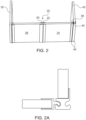
- FIG. 2-4 illustrate one example, not falling under the scope of the appended claims, of a bi-fold door having a curved central hinge 20.
- the curved central hinge 20 may be formed by a convexly curved portion 22 on a first panel 24 and a concave curved portion 26 on a second panel 28.
- the convexly curved portion 22 and concave curved portion 26 cooperate with respect to one another in order to help define the curved central hinge 20.
- Central hinge 20 may also be defined by a rear hinge pin or a rear piano-type hinge 21 that helps secure the two panels 24, 28 of the bi-fold door to one another, shown in FIG. 2A . This feature can also help ensure that the doors stay air tight, preventing any heat loss of chilled air from the compartments.
- the second panel 28 may have a side edge 30 that is installed with respect to the compartment 14 in a stable manner. This means that the side edge 30 stays secured with respect to the trolley compartment wall 32, although it is allowed to pivot with respect thereto as the bi-fold door is opened and closed.
- Side edge 30 is shown having an optional concave curved surface 34 that cooperates with a corresponding outward curve 36 on the wall 32. Securement of the side edge 30 to the door may be via a rear hinge pin or a piano-type hinge, as described above.
- the first panel 24 is an opening/movable panel.
- panel 24 has a side edge 38 with a curved tooth 40.
- the corresponding compartment wall 42 is provided with a corresponding curved receiver 44.
- the curved tooth 40 engages the curved receiver 44 in order to secure the first panel 24 with respect to the wall 42. This may help provide a greater force support than a typical side latch or lock. This may also help provide a greater force support as compared to a more standard wall connection.
- the tooth may be a rectangularly angled latch that cooperates with a corresponding rectangularly angled receiver.
- FIG. 2 illustrates the panels 24, 28 in a closed configuration.
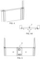
- FIG. 3 illustrates the panels as they are beginning to be opened, as the curved tooth 40 releases from the corresponding curved receiver 44.
- FIG. 4 shows a close-up view of cooperation between the curved tooth 40 and the corresponding curved receiver 44.
- Inner arm surface 66 is shown as a straight surface, but it should be understood that any other shape or configuration is possible, as long as inner arm surface 66 corresponds to the outer surface of second arm 54.
- the first arm 52 terminates at a base 68 defining a second angled edge 70.
- the second arm 54 has corresponding mating features, but in reverse. More specifically, second arm 54 defines a rear arm. Its arm mating surface 72 has an angled edge 74 that cooperates with second angled edge 70 of the first arm 52. An elbow 76 of the second arm 54 rests against the intersection of the inner arm surface 60 and the base 68. The remainder of arm mating surface 72 of the second arm 54 defines a surface that abuts the inner arm surface of the first arm 42. A mating ledge 78 of the second arm 54 receives the angled edge 62 of the first arm 52. When the bi-fold door is closed 10, the components all align as illustrated by FIG. 5A . The presence of the first arm that overlaps the second 54 provides a reinforced door system that can withstand higher forces. The angled faces and ledges help ensure that the arms 52, 54 will not slide or otherwise move out of alignment with one another.
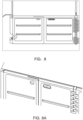
- FIG. 8 illustrates an embodiment in which the interfacing faces are more angular. They need not be exactly 90 degrees with respect to one another, but they are closer to right angles than the FIG. 5-7 embodiment.
- FIGS. 5-7 also illustrate a locking feature 58 that defines a dual lock system.
- the dual lock system has first and second lock portions 84, 86. Because the lock portions 84, 86 have similar features, only one of the lock portions will be described. However, it should be understood that more than two lock features may be provided for added locking security.
- the dual locking systems must be independent from each other, so that if one locking system fails, the other locking system will still work.
- the lock features may be provided in different configurations, such as one being more horizontally aligned and the other being more vertically aligned.
- lock bars 88, 90 Releasing pressure on the latches causes the lock bars 88, 90 to extend back through the lock body and to engage the securement positions 96, 98 when the first and second panels 24, 28 are aligned in planar cooperation. It should be understood that the positions of the lock bars 88, 90 and the securement positions 96, 98 may be moved between panels. In an alternate embodiment, one lock 84 is mounted on one of the panels and a second lock 86 is mounted on the other of the panels.
- both latches 102, 106 When both latches 102, 106 are activated, both elongated lock bars 104, 108 are raised and both locking modules 110, 112 are pulled back, retracting pins 116, and the first panel is allowed to hinge away from the second panel. When both latches 102, 106 are released, both elongated lock bars 104, 108 return to their original position and the locking modules 110, 112 cause pins 116 to extend into the opposite panel by the reactive spring 114 force, such that the door is locked closed.
- the locking modules are separate but operated using the latches 102, 106.
- FIG. 10 illustrates three separate locking systems 100, activated via one latch assembly 102, 106, and connected via extended lock bars 104, 108. It is possible, however, to provide only a single locking system, two locking systems, or more than three locking systems, depending upon door size and expected force.
- the first panel is hinged to a first trolley compartment wall at a first load transferring attachment point and the second panel is removably securable to a second trolley compartment wall at a second load transferring attachment point.
- the latches can be integrated in the door/ workdeck and have a more elegant and smooth look because they are not functioning as high loaded parts.
- the bumpers on the inside of the door can be located close to the side walls.
Landscapes
- Engineering & Computer Science (AREA)
- Civil Engineering (AREA)
- Structural Engineering (AREA)
- Mechanical Engineering (AREA)
- Aviation & Aerospace Engineering (AREA)
- Extensible Doors And Revolving Doors (AREA)
- Devices For Warming Or Keeping Food Or Tableware Hot (AREA)
- Refrigerator Housings (AREA)
Description
- This application claims the benefit of
U.S. Provisional Application Serial No. 62/474,271, filed March 21, 2017 - Embodiments of the present disclosure relate generally to galley trolley compartment doors that replace traditional trolley retainer latches used to secure trolleys when positioned in galley compartments. Even instances of trolley compartments that used trolley doors still needed to use retainer latches because the doors were not designed to withstand required loads. The galley trolley compartment doors described herein are designed with engaging and overlapping arms that help secure the trolleys in place under required flight loads and emergency crash loads. Some embodiments of the galley trolley compartment doors are designed with thicknesses that can help improve cooling of the trolley compartment.
- Aircraft and other passenger transportation vehicles are often provided with galleys or other food preparation areas in which trolleys are stored. Trolleys are traditionally used to hold meals, snacks, drinks, and other passenger nourishment or consumable items. The trolleys are wheeled in the aisle to offer meal and beverage service, and are typically stored in a galley area when not in use.
- When not in use, storage of trolleys in galley compartments has traditionally been secured by dual latches. Dual latches are generally required in order to provide primary and secondary retention systems. Examples are of prior art dual latches illustrated by
FIG. 13 . The dual latches are integrated into an upper part of the galley work deck and often require a reinforced work deck due to the required structural loads of the trolleys that the latches must support. For example, the latches must support a force that is many times the weight of the trolleys, which is mainly driven by flight loads as well as required emergency crash loads. - The retaining devices also protrude to the front, such that they stick out from the front face of the doors/trolleys. In many aircraft galley designs, this protrusion can create a problem where additional space for such protrusion is not readily available and/or where protrusion is otherwise undesirable, for example, escape path routing. Improved retaining methods are desired.
- Additionally, in certain instances, in addition to the dual latches, some trolley compartments have also been provided with doors intended to retain any cooled air within the trolley compartment. However, this can result in lost space due to the space required by the door (typically 2.54 cm (one inch)) in addition to the space required by the retainers (also typically 2.54 cm (one inch)). These doors are not designed to be retention doors; trolley retention has still been primarily maintained by the dual latches (although in some instances when doors have been used, the door hinge has supported part of the load as well).
-
US 2016/264246 A1 discloses a galley comprising a bi-fold door. The bi-fold door comprises two panels that are connected to each other by a hinge. A gap between the panels is covered by a seal formed therebetween. - A trolley compartment door system is provided as claimed in claim 1. The bi-folded door transfers structural loads to the first and second trolley compartment side walls and not locally via latches. This transfer is substantially evenly distributed. The first and second arms may be provided on end caps that are secured to the first and second panels.
- Other examples include a locking feature. In one instance, the locking feature is a dual locking feature with first and second latches that operate first and second lock bars. The first and second latches can be activated simultaneously via one hand.
- It is possible to provide the first and second panels as insulated in order to maintain chilled air in the trolley compartment.
-
-
FIG. 1 shows a perspective view of a galley monument with trolley compartments being enclosed by two sets of bi-fold doors. -
FIG. 2 shows a front perspective view of a bi-fold door with a curved central hinge, an example not falling under the scope of the appended claims. -
FIG. 2A shows a close up view of the point at which one of the panels is removably securable to a trolley compartment side wall at a load transferring attachment point. -
FIG. 3 shows a front perspective view of the example, not falling under the scope of the appended claims, ofFIG. 2 partially opened. -
FIG. 3A shows a close up view of the point at which one of the panels is being removed from a trolley compartment side wall for bi-folding of the panels with respect to one another. -
FIG. 4 shows a close-up view of an example, not falling under the scope of the appended claims, of a wall connection option for a bi-fold door system. -
FIG. 4A shows a top plan view of a rear hinge that may be used with the embodiments ofFIG. 2 orFIG. 4 . -
FIG. 5 shows a front perspective view of one embodiment of a bi-fold door with an overlapping arm configuration. -
FIG. 5A shows a close-up view of overlapping arms. -
FIG. 6 shows the overlapping arms ofFIG. 5 as they are beginning to hinge away from one another. -
FIG. 7 shows the overlapping arms ofFIG. 5 as the bi-fold door is being opened. -
FIG. 8 shows a front perspective view of one embodiment of a bi-fold door having overlapping arms with right angled ledges that cooperate/abut one another. -
FIG. 8A shows a top perspective view of the overlapped arms. -
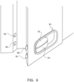
FIG. 9 shows a close-up view of one embodiment of a latching or locking system. -
FIG. 10 shows a front plan view of a bi-fold door with three locking modules, with dual bolt locks and a set of dual latches. -
FIG. 11 shows a close up view of cooperation between the latches, elongated lock bars, and locking modules. -
FIG. 11A shows an additional view of latches with bolts in a locked configuration. -
FIG. 11B shows the latches activated and the bolts in an unlocked configuration. -
FIG. 12A shows a top plan view of two fill size trolleys positioned in the trolley compartment. -
FIG. 12B shows a top plan view of four half size trolleys positioned in the trolley compartment. -
FIG. 13 shows a front perspective view of prior art dual latches used to secure trolleys in place in a trolley compartment. - Embodiments of the present invention provide bi-fold doors for installation in front of the trolley compartments. One side of the bi-fold door is positioned with respect to a retaining wall feature when the door is closed and the folding hinge portion is straightened. When the bi-fold door is opened, one stable end stays secured with respect to the trolley compartment wall, and an opening/moveable end moves sideways. This movement may occur within a track that is fixed to the galley work deck or other upper and/or lower structure. Internal bumpers or seals may also be provided. This can ensure a leak-proof sealed and retained connection. This can also improve the chilled compartment functionality. The panels of the bi-fold door may be latched or locked to one another when folded together by an interlink, lock, or (slide) latch mechanism, which prevents the panels from hinging with respect to one another when closed. This in turn prevents the door from moving out of its retaining wall feature.
- Referring now to
FIG. 1 , one embodiment of abi-fold door 10 configuration is illustrated. In this example, twobi-fold doors 10 are shown. Thedoors 10 are mounted with respect to agalley monument 12 and enclose galley trolley compartments 14. Although described with respect to a galley monument, it should be understood that the doors described herein may be used with respect to any trolley storage compartment.FIG. 1 illustrates two separate side-by-side trolley compartments 14. Eachtrolley compartment 14 is sized to receive two fullsized trolleys 16, as illustrated byFIG. 12A . Alternatively, the same sized trolley compartment may received four half size trolleys, in front to back configuration, as illustrated byFIG. 12B . Half size trolleys generally have the same width as full size trolleys, but are half of the length. - In this example, each
trolley compartment 14 has abi-fold door 10 that opens inwardly, toward acenter line 18, and toward abi-fold door 10 of anadjacent compartment 14. It should be understood that a single bi-fold door may be used to enclose a single compartment. It should also be understood that the bi-fold doors may be any appropriate size, and that it is possible to incorporate doors according to this disclosure for larger or smaller compartments, simply by altering the size of the door panels. -
FIG. 2-4 illustrate one example, not falling under the scope of the appended claims, of a bi-fold door having a curvedcentral hinge 20. The curvedcentral hinge 20 may be formed by a convexlycurved portion 22 on afirst panel 24 and a concavecurved portion 26 on asecond panel 28. The convexlycurved portion 22 and concavecurved portion 26 cooperate with respect to one another in order to help define the curvedcentral hinge 20. Central hinge 20 may also be defined by a rear hinge pin or a rear piano-type hinge 21 that helps secure the twopanels FIG. 2A . This feature can also help ensure that the doors stay air tight, preventing any heat loss of chilled air from the compartments. - The hinge 21 may function as a seal that also acts as the spring force to "straighten" the door panels closed. The rounded edges on both sides and on the curved
central hinge 20 can "slide" into the fixed rounded structures, creating a structural interconnection throughout the full vertical length of the hinge and side walls. For improved cooling (containment of chilled air in the compartment and cooled trolley contents), a seal can be integrated in the rounded/ curved area to close the leakage completely - The
second panel 28 may have a side edge 30 that is installed with respect to thecompartment 14 in a stable manner. This means that the side edge 30 stays secured with respect to thetrolley compartment wall 32, although it is allowed to pivot with respect thereto as the bi-fold door is opened and closed. Side edge 30 is shown having an optional concave curved surface 34 that cooperates with a corresponding outward curve 36 on thewall 32. Securement of the side edge 30 to the door may be via a rear hinge pin or a piano-type hinge, as described above. - The
first panel 24 is an opening/movable panel. In the example shown,panel 24 has aside edge 38 with acurved tooth 40. Thecorresponding compartment wall 42 is provided with a correspondingcurved receiver 44. In use, thecurved tooth 40 engages thecurved receiver 44 in order to secure thefirst panel 24 with respect to thewall 42. This may help provide a greater force support than a typical side latch or lock. This may also help provide a greater force support as compared to a more standard wall connection. However, it should be understood that rather than the curved tooth configuration, it is possible for alternate shapes to be provided. For example, the tooth may be a rectangularly angled latch that cooperates with a corresponding rectangularly angled receiver. As shown, thecurved portions receiver 40, 44 (or other shapes, if provided) may all be provided onend cap portions 46 that are secured to thepanels separate end caps 46 that mate or otherwise cooperate with one another as desired. -
FIG. 2 illustrates thepanels FIG. 3 illustrates the panels as they are beginning to be opened, as thecurved tooth 40 releases from the correspondingcurved receiver 44.FIG. 4 shows a close-up view of cooperation between thecurved tooth 40 and the correspondingcurved receiver 44. -
FIGS. 5-7 illustrates a bi-fold door with an overlapping arm configuration 50. This overlapping arm configuration 50 provides additional strength to the bi-fold door locking and latching and allows it to withstand the high forces required by many federal aviation regulations. Thepanels arms first panel 24 inFIGS. 6 and 7 ) has anoutward face 56 with dual locking features, described further below. As illustrated byFIGS. 5 and5A , thefirst arm 52 also has aninner face 60. Theinner face 60 of thefirst arm 52 is shaped as having a firstangled edge 62 defined between anarm tip 64 and aninner arm surface 66. (Inner arm surface 66 is shown as a straight surface, but it should be understood that any other shape or configuration is possible, as long asinner arm surface 66 corresponds to the outer surface ofsecond arm 54.) Thefirst arm 52 terminates at a base 68 defining a secondangled edge 70. - The
second arm 54 has corresponding mating features, but in reverse. More specifically,second arm 54 defines a rear arm. Itsarm mating surface 72 has an anglededge 74 that cooperates with secondangled edge 70 of thefirst arm 52. Anelbow 76 of thesecond arm 54 rests against the intersection of theinner arm surface 60 and thebase 68. The remainder ofarm mating surface 72 of thesecond arm 54 defines a surface that abuts the inner arm surface of thefirst arm 42. Amating ledge 78 of thesecond arm 54 receives theangled edge 62 of thefirst arm 52. When the bi-fold door is closed 10, the components all align as illustrated byFIG. 5A . The presence of the first arm that overlaps the second 54 provides a reinforced door system that can withstand higher forces. The angled faces and ledges help ensure that thearms - In certain embodiments, the components are provided as end caps 46 that can be positioned over the flat square edges of the door panels as shown in order to ease manufacturing.
FIG. 5A also illustrates asecurement hinge 80 that maintains thepanels hinge point 80 and locking area is long enough, the lock bar will be primarily loaded with shear loads. As illustrated byFIGS. 6 and 7 , as thepanels securement hinge 80. These figures also illustrate that the side on which the stable panel is secured may be provided with anintegrated hinge 82.Integrated hinge 82 provides a series of mating loops, in which every other loop appears on thepanel 24 or on thewall 42. A pin or other securement member may secure the panel to the wall in pivotable relationship. -
FIG. 8 illustrates an embodiment in which the interfacing faces are more angular. They need not be exactly 90 degrees with respect to one another, but they are closer to right angles than theFIG. 5-7 embodiment. -
FIGS. 5-7 also illustrate alocking feature 58 that defines a dual lock system. The dual lock system has first andsecond lock portions lock portions FIG. 9 illustrates each lock feature including afirst lock bar 88 and asecond lock bar 90. The lock bars 88, 90 are movable vialatches latches latches second panel 28. Releasing pressure on the latches causes the lock bars 88, 90 to extend back through the lock body and to engage the securement positions 96, 98 when the first andsecond panels lock 84 is mounted on one of the panels and asecond lock 86 is mounted on the other of the panels. -
FIGS. 10 and11 illustrate analternate locking system 100. In this example, afirst latch 102 activates a firstelongated lock bar 104, and asecond latch 106 activates a secondelongated lock bar 108. Eachelongated lock bar corresponding locking module more springs 114 may be positioned in recesses of the locking modules to help encourage movement of the extending pins 116. In use, when the firstelongated lock bar 104 is moved, it causes horizontal movement of thefirst locking module 110. When the secondelongated lock bar 108 is moved, it causes horizontal movement of thesecond locking module 112. When both latches 102, 106 are activated, both elongated lock bars 104, 108 are raised and both lockingmodules pins 116, and the first panel is allowed to hinge away from the second panel. When both latches 102, 106 are released, both elongated lock bars 104, 108 return to their original position and the lockingmodules reactive spring 114 force, such that the door is locked closed. The locking modules are separate but operated using thelatches FIG. 10 illustrates threeseparate locking systems 100, activated via onelatch assembly - By using bi-folded door designs, structural loads will be transferred via the side walls and not locally via the latches. This transfer is substantially evenly distributed. For example, the first panel is hinged to a first trolley compartment wall at a first load transferring attachment point and the second panel is removably securable to a second trolley compartment wall at a second load transferring attachment point. Additionally, the latches can be integrated in the door/ workdeck and have a more elegant and smooth look because they are not functioning as high loaded parts. To keep the loads on the latches that are in the middle of the door system relatively low (so that the loads are primarily borne by the side wall retention area), the bumpers on the inside of the door can be located close to the side walls. If the trolley load or other force/load moves forward against the door bumpers, the load is introduced away from the middle latch and it will not create a large moment on it. The hinge and the retained side wall distribute all the force into the structure, via the full vertical area. This re-positioning and differentiating of the retainers for galley trolley doors prevents the load from being directed into the work-deck, but instead into the sidewalls (closer to the floor fittings).
- It is also possible to provide the bi-fold doors with insulating properties, such that when the doors are closed, cooled air from the trolleys is maintained in the trolley compartment. Providing a layer of insulation on the doors and/or manufacturing the doors out of an insulating material can help minimize heat loss through the doors. Various materials have been explored for this purposes. Nonlimiting examples include foam materials, vacuum insulated panels, honeycomb panels, or combinations thereof. The doors may be made thicker in order to improve cooling, particularly due to the space saved by being able to remove the dual retainer latches. It is also possible to manufacture the doors of a heavier material that can withstand higher stress loads. Providing the latching system directly into the side wall of the compartment frees the workdeck from having the be designed for load handling.
- The disclosed galley compartment doors provide a new look and feel to crew and passengers (smooth surface/ aligned latches), easily opening and closing (leak-tight) without providing excessive force by the crew, and provide the highest load/ force possible on the door with minimal enhancements in surrounding structures.
- Changes and modifications, additions and deletions may be made to the structures and methods recited above and shown in the drawings without departing from the scope of the following claims.
Claims (7)
- A trolley compartment door system, comprising:a first trolley compartment side wall including a first load transferring attachment point,a second trolley compartment side wall including a second load transferring attachment point,first (24) and second (28) panels configured to cooperate as a bi-fold door,the first panel (24) comprising a first arm (52),the second panel (28) comprising a second arm (54),characterized in that the first (24) and second (28) arms are hinged to one another and the first (24) and second (28) arms overlap when the bi- fold door is closed,wherein the first panel (24) is hinged to the first trolley compartment side wall at the first load transferring attachment point;wherein the second panel (28) is removably securable to the second trolley compartment side wall at the second load transferring attachment point; andcharacterised in thatthe first arm (52) has an inner face (60) with at least one angled surface, wherein the second arm (54) has an arm mating surface with at least one angled edge (62) that corresponds to the at least one angled surface.
- The system of claim 1, wherein the bi-folded door transfers structural loads substantially evenly distributed to the first and second trolley compartment side walls and not locally via the latches.
- The system of either of the preceding claims, wherein the first (24) and second (28) arms are provided on end caps (46) that are secured to the first and second panels.
- The system of any of the preceding claims, further comprising a locking feature.
- The system of claim 4, wherein the locking feature comprises a dual locking feature with first (102) and second (106) latches that operate first and second lock bars.
- The system of claim 5, wherein the first (102) and second (106) latches can be activated simultaneously via one hand.
- The system of any of the preceding claims, wherein the first (24) and second (28) panels are insulated.
Applications Claiming Priority (2)
| Application Number | Priority Date | Filing Date | Title |
|---|---|---|---|
| US201762474271P | 2017-03-21 | 2017-03-21 | |
| PCT/IB2018/051904 WO2018172960A1 (en) | 2017-03-21 | 2018-03-21 | Galley trolley compartment doors |
Publications (2)
| Publication Number | Publication Date |
|---|---|
| EP3601049A1 EP3601049A1 (en) | 2020-02-05 |
| EP3601049B1 true EP3601049B1 (en) | 2024-07-03 |
Family
ID=61868559
Family Applications (1)
| Application Number | Title | Priority Date | Filing Date |
|---|---|---|---|
| EP18715134.5A Active EP3601049B1 (en) | 2017-03-21 | 2018-03-21 | Galley trolley compartment doors |
Country Status (4)
| Country | Link |
|---|---|
| US (1) | US10907390B2 (en) |
| EP (1) | EP3601049B1 (en) |
| CN (1) | CN110461711B (en) |
| WO (1) | WO2018172960A1 (en) |
Families Citing this family (12)
| Publication number | Priority date | Publication date | Assignee | Title |
|---|---|---|---|---|
| US11235879B2 (en) * | 2016-07-12 | 2022-02-01 | B/E Aerospace, Inc. | Aircraft service trolley and galley enclosure therefor |
| GB2585942B (en) * | 2019-07-26 | 2021-10-27 | Kingsway Enterprises Uk Ltd | Door leaf |
| US11420748B2 (en) * | 2019-08-16 | 2022-08-23 | B/E Aerospace, Inc. | Galley cart extraction and retention system for multiple-cart bays |
| US11529987B2 (en) | 2020-10-05 | 2022-12-20 | B/E Aerospace, Inc. | Aircraft cart retention system |
| US12320171B2 (en) * | 2020-12-15 | 2025-06-03 | B/E Aerospace Inc. | Sliding latch for galley bay doors |
| CA3211342A1 (en) * | 2021-03-09 | 2022-09-15 | Matthew Brown | Bifold door for moveable wall system |
| EP4144641B1 (en) * | 2021-09-02 | 2025-03-26 | B/E Aerospace, Inc. | Equipment for use in galleys in vessels |
| US11958403B2 (en) * | 2022-05-23 | 2024-04-16 | Caterpillar Inc. | Rooftop structure for semi-autonomous CTL |
| US12365464B2 (en) * | 2023-03-06 | 2025-07-22 | Airbus (S.A.S.) | Galley for aircraft comprising a trolley locking system |
| EP4559812A1 (en) * | 2023-11-21 | 2025-05-28 | B/E Aerospace (UK) Limited | Retainer |
| US20250304235A1 (en) * | 2024-03-28 | 2025-10-02 | The Boeing Company | Door Assembly with an Engagement Assembly |
| US20250305325A1 (en) * | 2024-03-28 | 2025-10-02 | The Boeing Company | Barrier Door with Hinged Lock |
Family Cites Families (45)
| Publication number | Priority date | Publication date | Assignee | Title |
|---|---|---|---|---|
| US2788067A (en) * | 1953-07-17 | 1957-04-09 | Miner Inc W H | Combined latch means and door fasteners for hinge supported door structures |
| US3103968A (en) * | 1962-06-19 | 1963-09-17 | Goetaverken Ab | Apparatus for articulating hingedly connected parts |
| US3302690A (en) * | 1964-05-04 | 1967-02-07 | Raymond M Hurd | Guard for multiple sectioned doors |
| US3400749A (en) * | 1966-04-12 | 1968-09-10 | Leland C. Smith | Bifold door handle |
| US3813730A (en) * | 1973-02-23 | 1974-06-04 | L Smith | Hinges for use on folding doors and the like |
| US3871083A (en) * | 1973-12-06 | 1975-03-18 | Lester L Smith | Folding door hardware |
| US4199176A (en) * | 1978-06-05 | 1980-04-22 | Kelly Joe L | Dead bolt cable lock |
| US4191412A (en) * | 1978-06-16 | 1980-03-04 | Lyon Metal Products, Incorporated | Door closure apparatus |
| US4620581A (en) * | 1983-09-21 | 1986-11-04 | Wallace Howard K | Insulation and security shutter |
| JPH0349271Y2 (en) * | 1984-12-10 | 1991-10-21 | ||
| US4607965A (en) * | 1985-03-08 | 1986-08-26 | Belanger, Inc. | Composite bearing with metal housing having a bore, with a tubular plastic insert therein |
| DE3726699C5 (en) * | 1987-08-11 | 2009-05-28 | Hörmann KG Brockhagen | Sectional |
| US5002114A (en) * | 1988-11-25 | 1991-03-26 | Hormann Kg Brockhagen | Overhead door |
| GB9214886D0 (en) * | 1992-07-14 | 1992-08-26 | James And Bloom Limited | Sliding shutters and doors |
| US5522446A (en) * | 1994-06-15 | 1996-06-04 | Wayne-Dalton Corp. | Sectional overhead door |
| US5601131A (en) * | 1996-01-02 | 1997-02-11 | Morris; Drew W. | Canopy-forming door |
| DE29800908U1 (en) * | 1998-01-20 | 1998-05-28 | MARANTEC Antriebs- und Steuerungstechnik GmbH & Co. Produktions-KG, 33428 Marienfeld | Door leaf |
| JP3057092U (en) | 1998-08-28 | 1999-03-26 | 利夫 永見 | Brush comb |
| JP3060139U (en) * | 1998-11-13 | 1999-07-30 | 株式会社ジャムコ | Door latch device |
| US6360487B1 (en) * | 1999-09-10 | 2002-03-26 | Rite-Hite Holding Corporation | Resilient door panel |
| US6363993B1 (en) * | 2000-02-28 | 2002-04-02 | Anthony George Aquilina | Pivoting bracket for connecting articulated door panels |
| US6672362B1 (en) * | 2000-11-10 | 2004-01-06 | Wayne-Dalton Corp. | Upward acting sectional door |
| US6470952B1 (en) * | 2001-06-06 | 2002-10-29 | John Cline | Bi-folding door |
| US7055573B2 (en) * | 2002-04-25 | 2006-06-06 | Martin Door Manufacturing | Systems and methods for reducing gap space between door sections |
| FR2851329B1 (en) * | 2003-02-17 | 2006-02-03 | Airbus | METHOD OF MAINTAINING COLD FOOD ON AIRCRAFT AND MEANS FOR IMPLEMENTING THE SAME |
| US6823927B2 (en) * | 2003-03-05 | 2004-11-30 | Charles F. Steel | Pocket door with pivoting panel |
| US7134471B2 (en) * | 2004-01-14 | 2006-11-14 | Wayne-Dalton Corp. | Pinch resistant sectional door with decorative components and method of attachment |
| US20050241781A1 (en) * | 2004-04-28 | 2005-11-03 | Johnson James A | Bi-fold door system |
| US7681621B2 (en) * | 2005-07-01 | 2010-03-23 | Metecno Panel Systems, Inc. | Pinch free panel system and method |
| EP2078813A3 (en) * | 2008-01-14 | 2014-03-12 | Hunter Douglas Industries B.V. | Actuating system and folding panel assembly |
| US8167386B2 (en) * | 2009-03-26 | 2012-05-01 | American Power Conversion Corporation | Door assembly and method of replacing a door of an electronics cabinet |
| US8322654B2 (en) * | 2009-11-02 | 2012-12-04 | Embraer S.A. | Aircraft galley units |
| JP2011162994A (en) * | 2010-02-09 | 2011-08-25 | Daiken Corp | Folding door |
| DE102011109390A1 (en) * | 2011-08-04 | 2013-02-07 | Airbus Operations Gmbh | Aircraft monument with a sanitary module and a kitchen module |
| US8918929B2 (en) * | 2012-05-30 | 2014-12-30 | Peter Kayser | Infant crib having paired sets of vertically hinged doors for creating opening along entire side wall |
| GB2511165B (en) | 2012-12-06 | 2017-05-24 | Era Home Security Ltd | Multi-sash closure system |
| EP2935741B1 (en) * | 2012-12-21 | 2019-04-24 | Centor Design Pty Ltd. | Latch mechanism |
| US8819993B1 (en) * | 2013-03-06 | 2014-09-02 | Nien Made Enterprise Co., Ltd. | Covering of building's opening |
| US8979140B2 (en) * | 2013-03-12 | 2015-03-17 | I-Tek Metal Mfg. Co., Ltd. | Latch with an automatic locking function for a double door |
| US9428259B2 (en) * | 2014-03-27 | 2016-08-30 | C&D Zodiac, Inc. | Bi-fold door module |
| WO2015148813A1 (en) | 2014-03-27 | 2015-10-01 | C&D Zodiac, Inc. | Bi-fold door module |
| US20180209206A1 (en) * | 2014-09-24 | 2018-07-26 | Lawrence Castaldi, III | Trackless Free-Swinging Bi-fold Door |
| US9802704B2 (en) * | 2015-03-13 | 2017-10-31 | The Boeing Company | Folding galley unit |
| US9428940B1 (en) * | 2015-06-05 | 2016-08-30 | Clarence E. Patrick | Three-way door latch |
| US11235879B2 (en) * | 2016-07-12 | 2022-02-01 | B/E Aerospace, Inc. | Aircraft service trolley and galley enclosure therefor |
-
2018
- 2018-03-21 WO PCT/IB2018/051904 patent/WO2018172960A1/en not_active Ceased
- 2018-03-21 CN CN201880020060.6A patent/CN110461711B/en active Active
- 2018-03-21 EP EP18715134.5A patent/EP3601049B1/en active Active
- 2018-03-21 US US15/927,457 patent/US10907390B2/en active Active
Also Published As
| Publication number | Publication date |
|---|---|
| CN110461711A (en) | 2019-11-15 |
| WO2018172960A1 (en) | 2018-09-27 |
| US20180273157A1 (en) | 2018-09-27 |
| EP3601049A1 (en) | 2020-02-05 |
| CN110461711B (en) | 2023-05-16 |
| US10907390B2 (en) | 2021-02-02 |
Similar Documents
| Publication | Publication Date | Title |
|---|---|---|
| US10907390B2 (en) | Galley trolley compartment doors | |
| US10647403B2 (en) | Actuatable emergency exit door and an aircraft or space craft with a pressurized cabin having such an actuatable emergency exit door | |
| EP1858367B1 (en) | Device for accommodating objects, as well as transport means | |
| US9695619B2 (en) | Galley cart bay door latch | |
| US10843799B2 (en) | Contoured class divider | |
| CN114599583B (en) | Passenger seating unit with multi-rail sliding doors | |
| JP6721355B2 (en) | Overhead storage rack assembly for vehicles | |
| EP2736806B1 (en) | Aircraft luggage bin | |
| EP2640638B1 (en) | Stowage bin with shear fittings | |
| EP2841670B1 (en) | Device for accommodating objects and transportation means comprising such a device | |
| WO2015148813A1 (en) | Bi-fold door module | |
| EP4051592B1 (en) | Passenger seat unit with foldable door | |
| US12434856B2 (en) | Bi-fold barrier system and method for a flight deck of an aircraft | |
| US20250340300A1 (en) | Seat unit with a movable privacy shield | |
| EP3964445B1 (en) | Variable width door for cockpit secondary barrier and other aircraft cabin applications | |
| US10597135B2 (en) | Aircraft cell comprising a door opening in rectilinear translation | |
| JP2001514373A (en) | Explosion-proof assembly including interengageable flanges | |
| US12145729B2 (en) | Galley isolation panels | |
| EP3386860B1 (en) | Storage bin with luggage positioning protrusions | |
| US20250128815A1 (en) | Barrier system and method for a flight deck of an aircraft | |
| US20220227493A1 (en) | Seat assembly, in particular for an aircraft | |
| US20260054836A1 (en) | System and method for restraining a galley cart within an internal cabin of an aircraft | |
| EP2707283B1 (en) | Aircraft cabin trolley securing device |
Legal Events
| Date | Code | Title | Description |
|---|---|---|---|
| STAA | Information on the status of an ep patent application or granted ep patent |
Free format text: STATUS: UNKNOWN |
|
| STAA | Information on the status of an ep patent application or granted ep patent |
Free format text: STATUS: THE INTERNATIONAL PUBLICATION HAS BEEN MADE |
|
| PUAI | Public reference made under article 153(3) epc to a published international application that has entered the european phase |
Free format text: ORIGINAL CODE: 0009012 |
|
| STAA | Information on the status of an ep patent application or granted ep patent |
Free format text: STATUS: REQUEST FOR EXAMINATION WAS MADE |
|
| 17P | Request for examination filed |
Effective date: 20191018 |
|
| AK | Designated contracting states |
Kind code of ref document: A1 Designated state(s): AL AT BE BG CH CY CZ DE DK EE ES FI FR GB GR HR HU IE IS IT LI LT LU LV MC MK MT NL NO PL PT RO RS SE SI SK SM TR |
|
| AX | Request for extension of the european patent |
Extension state: BA ME |
|
| DAV | Request for validation of the european patent (deleted) | ||
| DAX | Request for extension of the european patent (deleted) | ||
| STAA | Information on the status of an ep patent application or granted ep patent |
Free format text: STATUS: EXAMINATION IS IN PROGRESS |
|
| 17Q | First examination report despatched |
Effective date: 20210304 |
|
| GRAP | Despatch of communication of intention to grant a patent |
Free format text: ORIGINAL CODE: EPIDOSNIGR1 |
|
| STAA | Information on the status of an ep patent application or granted ep patent |
Free format text: STATUS: GRANT OF PATENT IS INTENDED |
|
| INTG | Intention to grant announced |
Effective date: 20240201 |
|
| GRAS | Grant fee paid |
Free format text: ORIGINAL CODE: EPIDOSNIGR3 |
|
| GRAA | (expected) grant |
Free format text: ORIGINAL CODE: 0009210 |
|
| STAA | Information on the status of an ep patent application or granted ep patent |
Free format text: STATUS: THE PATENT HAS BEEN GRANTED |
|
| AK | Designated contracting states |
Kind code of ref document: B1 Designated state(s): AL AT BE BG CH CY CZ DE DK EE ES FI FR GB GR HR HU IE IS IT LI LT LU LV MC MK MT NL NO PL PT RO RS SE SI SK SM TR |
|
| REG | Reference to a national code |
Ref country code: CH Ref legal event code: EP |
|
| REG | Reference to a national code |
Ref country code: DE Ref legal event code: R096 Ref document number: 602018071255 Country of ref document: DE |
|
| REG | Reference to a national code |
Ref country code: LT Ref legal event code: MG9D |
|
| REG | Reference to a national code |
Ref country code: NL Ref legal event code: MP Effective date: 20240703 |
|
| PG25 | Lapsed in a contracting state [announced via postgrant information from national office to epo] |
Ref country code: PT Free format text: LAPSE BECAUSE OF FAILURE TO SUBMIT A TRANSLATION OF THE DESCRIPTION OR TO PAY THE FEE WITHIN THE PRESCRIBED TIME-LIMIT Effective date: 20241104 |
|
| REG | Reference to a national code |
Ref country code: AT Ref legal event code: MK05 Ref document number: 1699576 Country of ref document: AT Kind code of ref document: T Effective date: 20240703 |
|
| PG25 | Lapsed in a contracting state [announced via postgrant information from national office to epo] |
Ref country code: NL Free format text: LAPSE BECAUSE OF FAILURE TO SUBMIT A TRANSLATION OF THE DESCRIPTION OR TO PAY THE FEE WITHIN THE PRESCRIBED TIME-LIMIT Effective date: 20240703 |
|
| PG25 | Lapsed in a contracting state [announced via postgrant information from national office to epo] |
Ref country code: PT Free format text: LAPSE BECAUSE OF FAILURE TO SUBMIT A TRANSLATION OF THE DESCRIPTION OR TO PAY THE FEE WITHIN THE PRESCRIBED TIME-LIMIT Effective date: 20241104 Ref country code: NL Free format text: LAPSE BECAUSE OF FAILURE TO SUBMIT A TRANSLATION OF THE DESCRIPTION OR TO PAY THE FEE WITHIN THE PRESCRIBED TIME-LIMIT Effective date: 20240703 |
|
| PG25 | Lapsed in a contracting state [announced via postgrant information from national office to epo] |
Ref country code: NO Free format text: LAPSE BECAUSE OF FAILURE TO SUBMIT A TRANSLATION OF THE DESCRIPTION OR TO PAY THE FEE WITHIN THE PRESCRIBED TIME-LIMIT Effective date: 20241003 |
|
| PG25 | Lapsed in a contracting state [announced via postgrant information from national office to epo] |
Ref country code: FI Free format text: LAPSE BECAUSE OF FAILURE TO SUBMIT A TRANSLATION OF THE DESCRIPTION OR TO PAY THE FEE WITHIN THE PRESCRIBED TIME-LIMIT Effective date: 20240703 Ref country code: GR Free format text: LAPSE BECAUSE OF FAILURE TO SUBMIT A TRANSLATION OF THE DESCRIPTION OR TO PAY THE FEE WITHIN THE PRESCRIBED TIME-LIMIT Effective date: 20241004 Ref country code: PL Free format text: LAPSE BECAUSE OF FAILURE TO SUBMIT A TRANSLATION OF THE DESCRIPTION OR TO PAY THE FEE WITHIN THE PRESCRIBED TIME-LIMIT Effective date: 20240703 |
|
| PG25 | Lapsed in a contracting state [announced via postgrant information from national office to epo] |
Ref country code: BG Free format text: LAPSE BECAUSE OF FAILURE TO SUBMIT A TRANSLATION OF THE DESCRIPTION OR TO PAY THE FEE WITHIN THE PRESCRIBED TIME-LIMIT Effective date: 20240703 |
|
| PG25 | Lapsed in a contracting state [announced via postgrant information from national office to epo] |
Ref country code: LV Free format text: LAPSE BECAUSE OF FAILURE TO SUBMIT A TRANSLATION OF THE DESCRIPTION OR TO PAY THE FEE WITHIN THE PRESCRIBED TIME-LIMIT Effective date: 20240703 |
|
| PG25 | Lapsed in a contracting state [announced via postgrant information from national office to epo] |
Ref country code: IS Free format text: LAPSE BECAUSE OF FAILURE TO SUBMIT A TRANSLATION OF THE DESCRIPTION OR TO PAY THE FEE WITHIN THE PRESCRIBED TIME-LIMIT Effective date: 20241103 Ref country code: AT Free format text: LAPSE BECAUSE OF FAILURE TO SUBMIT A TRANSLATION OF THE DESCRIPTION OR TO PAY THE FEE WITHIN THE PRESCRIBED TIME-LIMIT Effective date: 20240703 |
|
| PG25 | Lapsed in a contracting state [announced via postgrant information from national office to epo] |
Ref country code: CZ Free format text: LAPSE BECAUSE OF FAILURE TO SUBMIT A TRANSLATION OF THE DESCRIPTION OR TO PAY THE FEE WITHIN THE PRESCRIBED TIME-LIMIT Effective date: 20240703 Ref country code: HR Free format text: LAPSE BECAUSE OF FAILURE TO SUBMIT A TRANSLATION OF THE DESCRIPTION OR TO PAY THE FEE WITHIN THE PRESCRIBED TIME-LIMIT Effective date: 20240703 |
|
| PG25 | Lapsed in a contracting state [announced via postgrant information from national office to epo] |
Ref country code: RS Free format text: LAPSE BECAUSE OF FAILURE TO SUBMIT A TRANSLATION OF THE DESCRIPTION OR TO PAY THE FEE WITHIN THE PRESCRIBED TIME-LIMIT Effective date: 20241003 Ref country code: ES Free format text: LAPSE BECAUSE OF FAILURE TO SUBMIT A TRANSLATION OF THE DESCRIPTION OR TO PAY THE FEE WITHIN THE PRESCRIBED TIME-LIMIT Effective date: 20240703 |
|
| PG25 | Lapsed in a contracting state [announced via postgrant information from national office to epo] |
Ref country code: RS Free format text: LAPSE BECAUSE OF FAILURE TO SUBMIT A TRANSLATION OF THE DESCRIPTION OR TO PAY THE FEE WITHIN THE PRESCRIBED TIME-LIMIT Effective date: 20241003 Ref country code: PL Free format text: LAPSE BECAUSE OF FAILURE TO SUBMIT A TRANSLATION OF THE DESCRIPTION OR TO PAY THE FEE WITHIN THE PRESCRIBED TIME-LIMIT Effective date: 20240703 Ref country code: NO Free format text: LAPSE BECAUSE OF FAILURE TO SUBMIT A TRANSLATION OF THE DESCRIPTION OR TO PAY THE FEE WITHIN THE PRESCRIBED TIME-LIMIT Effective date: 20241003 Ref country code: LV Free format text: LAPSE BECAUSE OF FAILURE TO SUBMIT A TRANSLATION OF THE DESCRIPTION OR TO PAY THE FEE WITHIN THE PRESCRIBED TIME-LIMIT Effective date: 20240703 Ref country code: IS Free format text: LAPSE BECAUSE OF FAILURE TO SUBMIT A TRANSLATION OF THE DESCRIPTION OR TO PAY THE FEE WITHIN THE PRESCRIBED TIME-LIMIT Effective date: 20241103 Ref country code: HR Free format text: LAPSE BECAUSE OF FAILURE TO SUBMIT A TRANSLATION OF THE DESCRIPTION OR TO PAY THE FEE WITHIN THE PRESCRIBED TIME-LIMIT Effective date: 20240703 Ref country code: GR Free format text: LAPSE BECAUSE OF FAILURE TO SUBMIT A TRANSLATION OF THE DESCRIPTION OR TO PAY THE FEE WITHIN THE PRESCRIBED TIME-LIMIT Effective date: 20241004 Ref country code: FI Free format text: LAPSE BECAUSE OF FAILURE TO SUBMIT A TRANSLATION OF THE DESCRIPTION OR TO PAY THE FEE WITHIN THE PRESCRIBED TIME-LIMIT Effective date: 20240703 Ref country code: ES Free format text: LAPSE BECAUSE OF FAILURE TO SUBMIT A TRANSLATION OF THE DESCRIPTION OR TO PAY THE FEE WITHIN THE PRESCRIBED TIME-LIMIT Effective date: 20240703 Ref country code: CZ Free format text: LAPSE BECAUSE OF FAILURE TO SUBMIT A TRANSLATION OF THE DESCRIPTION OR TO PAY THE FEE WITHIN THE PRESCRIBED TIME-LIMIT Effective date: 20240703 Ref country code: BG Free format text: LAPSE BECAUSE OF FAILURE TO SUBMIT A TRANSLATION OF THE DESCRIPTION OR TO PAY THE FEE WITHIN THE PRESCRIBED TIME-LIMIT Effective date: 20240703 Ref country code: AT Free format text: LAPSE BECAUSE OF FAILURE TO SUBMIT A TRANSLATION OF THE DESCRIPTION OR TO PAY THE FEE WITHIN THE PRESCRIBED TIME-LIMIT Effective date: 20240703 |
|
| REG | Reference to a national code |
Ref country code: DE Ref legal event code: R097 Ref document number: 602018071255 Country of ref document: DE |
|
| PG25 | Lapsed in a contracting state [announced via postgrant information from national office to epo] |
Ref country code: DK Free format text: LAPSE BECAUSE OF FAILURE TO SUBMIT A TRANSLATION OF THE DESCRIPTION OR TO PAY THE FEE WITHIN THE PRESCRIBED TIME-LIMIT Effective date: 20240703 Ref country code: RO Free format text: LAPSE BECAUSE OF FAILURE TO SUBMIT A TRANSLATION OF THE DESCRIPTION OR TO PAY THE FEE WITHIN THE PRESCRIBED TIME-LIMIT Effective date: 20240703 Ref country code: SM Free format text: LAPSE BECAUSE OF FAILURE TO SUBMIT A TRANSLATION OF THE DESCRIPTION OR TO PAY THE FEE WITHIN THE PRESCRIBED TIME-LIMIT Effective date: 20240703 |
|
| PG25 | Lapsed in a contracting state [announced via postgrant information from national office to epo] |
Ref country code: EE Free format text: LAPSE BECAUSE OF FAILURE TO SUBMIT A TRANSLATION OF THE DESCRIPTION OR TO PAY THE FEE WITHIN THE PRESCRIBED TIME-LIMIT Effective date: 20240703 |
|
| PG25 | Lapsed in a contracting state [announced via postgrant information from national office to epo] |
Ref country code: IT Free format text: LAPSE BECAUSE OF FAILURE TO SUBMIT A TRANSLATION OF THE DESCRIPTION OR TO PAY THE FEE WITHIN THE PRESCRIBED TIME-LIMIT Effective date: 20240703 Ref country code: SK Free format text: LAPSE BECAUSE OF FAILURE TO SUBMIT A TRANSLATION OF THE DESCRIPTION OR TO PAY THE FEE WITHIN THE PRESCRIBED TIME-LIMIT Effective date: 20240703 |
|
| PLBE | No opposition filed within time limit |
Free format text: ORIGINAL CODE: 0009261 |
|
| STAA | Information on the status of an ep patent application or granted ep patent |
Free format text: STATUS: NO OPPOSITION FILED WITHIN TIME LIMIT |
|
| 26N | No opposition filed |
Effective date: 20250404 |
|
| PG25 | Lapsed in a contracting state [announced via postgrant information from national office to epo] |
Ref country code: SE Free format text: LAPSE BECAUSE OF FAILURE TO SUBMIT A TRANSLATION OF THE DESCRIPTION OR TO PAY THE FEE WITHIN THE PRESCRIBED TIME-LIMIT Effective date: 20240703 |
|
| PG25 | Lapsed in a contracting state [announced via postgrant information from national office to epo] |
Ref country code: MC Free format text: LAPSE BECAUSE OF FAILURE TO SUBMIT A TRANSLATION OF THE DESCRIPTION OR TO PAY THE FEE WITHIN THE PRESCRIBED TIME-LIMIT Effective date: 20240703 |
|
| REG | Reference to a national code |
Ref country code: CH Ref legal event code: H13 Free format text: ST27 STATUS EVENT CODE: U-0-0-H10-H13 (AS PROVIDED BY THE NATIONAL OFFICE) Effective date: 20251023 |
|
| PG25 | Lapsed in a contracting state [announced via postgrant information from national office to epo] |
Ref country code: LU Free format text: LAPSE BECAUSE OF NON-PAYMENT OF DUE FEES Effective date: 20250321 |
|
| REG | Reference to a national code |
Ref country code: BE Ref legal event code: MM Effective date: 20250331 |
|
| PG25 | Lapsed in a contracting state [announced via postgrant information from national office to epo] |
Ref country code: BE Free format text: LAPSE BECAUSE OF NON-PAYMENT OF DUE FEES Effective date: 20250331 |
|
| PG25 | Lapsed in a contracting state [announced via postgrant information from national office to epo] |
Ref country code: CH Free format text: LAPSE BECAUSE OF NON-PAYMENT OF DUE FEES Effective date: 20250331 |
|
| PG25 | Lapsed in a contracting state [announced via postgrant information from national office to epo] |
Ref country code: IE Free format text: LAPSE BECAUSE OF NON-PAYMENT OF DUE FEES Effective date: 20250321 |
|
| PGFP | Annual fee paid to national office [announced via postgrant information from national office to epo] |
Ref country code: GB Payment date: 20260324 Year of fee payment: 9 |
|
| PGFP | Annual fee paid to national office [announced via postgrant information from national office to epo] |
Ref country code: DE Payment date: 20260320 Year of fee payment: 9 |
|
| PGFP | Annual fee paid to national office [announced via postgrant information from national office to epo] |
Ref country code: FR Payment date: 20260324 Year of fee payment: 9 |