EP3601047B1 - Passenger communication system - Google Patents
Passenger communication system Download PDFInfo
- Publication number
- EP3601047B1 EP3601047B1 EP18718566.5A EP18718566A EP3601047B1 EP 3601047 B1 EP3601047 B1 EP 3601047B1 EP 18718566 A EP18718566 A EP 18718566A EP 3601047 B1 EP3601047 B1 EP 3601047B1
- Authority
- EP
- European Patent Office
- Prior art keywords
- mode
- visual indicator
- communication system
- modes
- sub
- Prior art date
- Legal status (The legal status is an assumption and is not a legal conclusion. Google has not performed a legal analysis and makes no representation as to the accuracy of the status listed.)
- Active
Links
Images


Classifications
-
- B—PERFORMING OPERATIONS; TRANSPORTING
- B64—AIRCRAFT; AVIATION; COSMONAUTICS
- B64D—EQUIPMENT FOR FITTING IN OR TO AIRCRAFT; FLIGHT SUITS; PARACHUTES; ARRANGEMENT OR MOUNTING OF POWER PLANTS OR PROPULSION TRANSMISSIONS IN AIRCRAFT
- B64D45/00—Aircraft indicators or protectors not otherwise provided for
-
- B—PERFORMING OPERATIONS; TRANSPORTING
- B64—AIRCRAFT; AVIATION; COSMONAUTICS
- B64D—EQUIPMENT FOR FITTING IN OR TO AIRCRAFT; FLIGHT SUITS; PARACHUTES; ARRANGEMENT OR MOUNTING OF POWER PLANTS OR PROPULSION TRANSMISSIONS IN AIRCRAFT
- B64D11/00—Passenger or crew accommodation; Flight-deck installations not otherwise provided for
- B64D11/0015—Arrangements for entertainment or communications, e.g. radio, television
-
- B—PERFORMING OPERATIONS; TRANSPORTING
- B64—AIRCRAFT; AVIATION; COSMONAUTICS
- B64D—EQUIPMENT FOR FITTING IN OR TO AIRCRAFT; FLIGHT SUITS; PARACHUTES; ARRANGEMENT OR MOUNTING OF POWER PLANTS OR PROPULSION TRANSMISSIONS IN AIRCRAFT
- B64D11/00—Passenger or crew accommodation; Flight-deck installations not otherwise provided for
- B64D11/0015—Arrangements for entertainment or communications, e.g. radio, television
- B64D11/00151—Permanently mounted seat back monitors
-
- B—PERFORMING OPERATIONS; TRANSPORTING
- B64—AIRCRAFT; AVIATION; COSMONAUTICS
- B64D—EQUIPMENT FOR FITTING IN OR TO AIRCRAFT; FLIGHT SUITS; PARACHUTES; ARRANGEMENT OR MOUNTING OF POWER PLANTS OR PROPULSION TRANSMISSIONS IN AIRCRAFT
- B64D11/00—Passenger or crew accommodation; Flight-deck installations not otherwise provided for
- B64D11/0015—Arrangements for entertainment or communications, e.g. radio, television
- B64D11/00155—Individual entertainment or communication system remote controls therefor, located in or connected to seat components, e.g. to seat back or arm rest
-
- B—PERFORMING OPERATIONS; TRANSPORTING
- B64—AIRCRAFT; AVIATION; COSMONAUTICS
- B64D—EQUIPMENT FOR FITTING IN OR TO AIRCRAFT; FLIGHT SUITS; PARACHUTES; ARRANGEMENT OR MOUNTING OF POWER PLANTS OR PROPULSION TRANSMISSIONS IN AIRCRAFT
- B64D45/00—Aircraft indicators or protectors not otherwise provided for
- B64D2045/007—Indicators or signs in the cabin, e.g. exit signs or seat numbering
Definitions
- the field of the invention relates to communication systems for passengers in seats for aircraft or the like.
- Arrangements of passenger seats, and particularly arrays of passenger seats in vehicles or aircraft are designed to ensure passenger safety, comfort, and convenience along with maximizing efficiencies related to tasks within the cabin of the vehicle including for example, distributing objects to the passengers or responding to requests for assistance.
- space in walkways/aisles of a vehicle cabin is limited due to standing passengers or airline products (such as beverage/meal carts).
- Conventional seats do not include any system for quickly identifying a plurality of statuses or conditions for a passenger of the seat.
- Flight attendants moving through the cabin of an aircraft may view visual indicators for each passenger, which will increase efficiency for typical airline tasks, expedite responses to medical concerns, and improve passenger experiences by limiting wait times and reducing unnecessary interruptions.
- a one-way communication system for a passenger seat that allows a passenger to provide notification of a status or condition such that the flight attendant can recognize the status without walking to the seat and/or without verbal communication with the passenger.
- Embodiments of the invention covered by this patent are defined by the dependent claims below, not this summary.
- This summary is a high-level overview of various aspects of the invention and introduces some of the concepts that are further described in the Detailed Description section below. This summary is not intended to identify key or essential features
- Document US2016/249073 describes a video display system for a passenger seat of a vehicle.
- the video display system is configured to be mounted to a seatback of each passenger seat or to other structure such that the system may be utilized by the passenger.
- the display system includes a video display assembly having a display housing configured to be mounted to structure in the vehicle.
- Document US2010/187354 describes an information system for an aircraft comprising an operating unit with input elements, a display unit arranged in the region of passenger accommodation, for displaying a message.
- the operating unit makes it possible to input a message from several selection options. of the claimed subject matter, nor is it intended to be used in isolation to determine the scope of the claimed subject matter.
- the subject matter should be understood by reference to appropriate portions of the entire specification of this patent, any or all drawings and each claim.
- the visual indicator displays a distinct visual indicia for each mode and the visual indicator comprises an LED light.
- the plurality of modes comprises a Do Not Disturb mode wherein the visual indicator illuminates as a solid red light.
- the plurality of modes comprises a Wake Me for Meals/Beverage mode wherein the visual indicator illuminates as a solid blue light.
- the plurality of modes comprises at least three of a Do Not Disturb mode, a Wake Me for Meals/Beverage mode, a Need Assistance mode, a Wake Me for Duty-Free mode, a Medical Emergency mode, and a Vacant Seat mode.
- the visual indicator is disposed on an upper surface of a seatback.
- the visual indicator in certain embodiments, further comprises an auxiliary light disposed in a gap in the seatback.
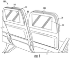
- Figs. 1-3C illustrate embodiments of passenger seats 100 that include a communication system for each passenger.
- the communication system includes a visual indicator 101 and a control portion 200 where the visual indicator 101 and the control portion 200 are electrically connected to one another.
- the visual indicator 101 is located on the top of the passenger seat 100 immediately in front of the passenger.
- the visual indicator 101 is disposed on a seatback located in front of a seated position for interfacing with the control portion 200.
- the visual indicator 101 may include a light, a small display screen, a combination thereof, or any other appropriate device.
- the visual indicator 101 is a light-emitting diode (LED) or an array of LEDs.
- the visual indicator 101 is configured to display multiple colors, optionally in combination with any of projected shapes/patterns, patterns of blinking lights, text, symbols, combinations thereof, or any other appropriate visual indicia.
- the visual indicator 101 may be located on an upper surface of a seatback 20 directly in front of the passenger that controls/operates the control portion 200.
- the communication system includes a display screen 10 that is electrically connected to the visual indicator 101.
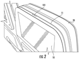
- the passenger seat 100 may include an auxiliary light 11 in a gap between the seatback 20 and the display screen 10.
- the auxiliary light 11 may operate in addition to or in lieu of the visual indicator 101.
- the auxiliary light 11 operates independently of the visual indicator 101.
- the visual indicator 101 may include a plurality of LED light sources, which allow the visual indicator 101 to display a plurality of colors.
- the visual indicator 101 includes a plurality of modes. For example, in a first mode during a flight in an aircraft, a passenger may need to alert a flight attendant that he/she should not be disturbed for any reason (i.e., Do Not Disturb mode).
- the visual indicator 101 may include a second mode asking for the flight attendant to wake or alert the passenger for a meal/beverage being distributed by the airline (i.e., Wake Me for Meals/Beverage mode).
- the visual indicator 101 may include a third mode asking for the flight attendant to wake or alert the passenger for duty-free products being sold in the aircraft (i.e., Wake Me for Duty-Free mode).
- the visual indicator 101 may include a fourth mode asking for the flight attendant for assistance (i.e., Need Assistance mode).
- the visual indicator 101 may include a fifth mode asking for immediate medical attention (i.e. , Medical Emergency mode).
- the visual indicator 101 may include a sixth mode to indicate to other passengers and/or flight attendants that the seat is vacant (i.e. , Vacant Seat mode). Although six modes are described above, alternative and/or additional modes may be included.
- the Do Not Disturb mode (the first mode) is represented by a color, and optionally a symbol, a blinking pattern, a combination thereof, or any other appropriate indicator.
- the visual indicator 101 may illuminate a solid yellow or red color (or any other color).
- the visual indicator 101 may illuminate a solid color with a single horizontal or diagonal line (or a pair of diagonal lines forming an "X").
- the line(s) may be black, white, and/or any other appropriate color.
- the visual indicator 101 may blink showing a solid color, a solid color with at least one line (as described above), or may alternate between these representations (or may alternate with other appropriate representations).
- the Wake Me for Meals/Beverage mode (the second mode) is represented by a color, and optionally a symbol, a blinking pattern, a combination thereof, or any other appropriate indicator.
- the visual indicator 101 may illuminate a solid blue color (or any other color).
- the visual indicator 101 may illuminate a solid color with a symbol of a fork and/or a knife.
- the visual indicator 101 may blink showing a solid color, a solid color with a symbol of a fork and/or a knife (as described above), or may alternate between these representations (or may alternate with other appropriate representations).
- the Wake Me for Duty-Free mode (the third mode) is represented by a color, and optionally a symbol, a blinking pattern, a combination thereof, or any other appropriate indicator.
- the visual indicator 101 may illuminate a solid green color (or any other color).
- the visual indicator 101 may illuminate a solid color with a currency symbol and/or a symbol of a bottle.
- the visual indicator 101 may blink showing a solid color, a solid color with a currency symbol and/or a symbol of a bottle (as described above), or may alternate between these representations (or may alternate with other appropriate representations).
- the Need Assistance mode (the fourth mode) is way represented by a color, and optionally a symbol, a blinking pattern, a combination thereof, or any other appropriate indicator.
- the visual indicator 101 may illuminate a solid purple color (or any other color).
- the visual indicator 101 may illuminate a solid color with a symbol such as a question mark.
- the visual indicator 101 may blink showing a solid color, a solid color with a question mark (as described above), or may alternate between these representations (or may alternate with other appropriate representations).
- the Medical Emergency mode (the fifth mode) is represented by a color, and optionally a symbol, a blinking pattern, a combination thereof, or any other appropriate indicator.
- the visual indicator 101 may illuminate a solid red color (or any other color).
- the visual indicator 101 may illuminate a solid color with a symbol such as the Star of Life or a red cross ("+") symbol.
- the visual indicator 101 may blink showing a solid color, a solid color with a symbol such as the Star of Life or a red cross ("+") symbol (as described above), or may alternate between these representations (or may alternate with other appropriate representations).
- the fifth mode may include a rapid or strobe blinking pattern.
- the Vacant Seat mode (the sixth mode) is represented by a color, and optionally a symbol, a blinking pattern, a combination thereof, or any other appropriate indicator.
- the visual indicator 101 may illuminate a solid white color (or any other color).
- the visual indicator 101 may illuminate a solid color with a symbol such as " ⁇ " or " ⁇ ".
- the visual indicator 101 may blink showing a solid color, a symbol such as " ⁇ " or " ⁇ ” (as described above), or may alternate between these representations (or may alternate with other appropriate representations).
- the communication system includes a control portion 200 which includes a master switch 201 that is on the display screen 10.
- the master switch 201 is an icon on the display screen 10 and is configured to open a sub-menu 202 on the display screen 10.
- the sub-menu 202 includes icons for a plurality of modes of the visual indicator 101.
- Fig. 3B shows icons 203-206, but the sub-menu 202 may include any number of icons for various modes including, but not limited to, the six modes described above.
- the sub-menu 202 may be customizable by the airline and/or the individual passenger such that the sub-menu 202 may include more or fewer icons.
- Fig. 3B shows one example of the sub-menu 202 that includes a first icon 203 for the Do Not Disturb mode, a second icon 204 for the Wake Me for Meals/Beverage mode, a third icon 205 for the Wake Me for Duty-Free mode, and a fourth icon 206 for the Need Assistance mode.
- the sub-menu 202 can be controlled/manipulated via a touchscreen interface.
- Fig. 3C illustrates one example of the sub-menu 202 where one of the modes has been activated.
- the portion of the sub-menu 202 surrounding the second icon 204 is illuminated or highlighted to indicate that the Wake Me for Meals/Beverage mode has been selected.
- the visual indicator 101 is activated with the appropriate visual indicia.
- the sub-menu 202 will disappear from the display screen 10 after a set time interval after a mode has been selected, while in other embodiments, the sub-menu 202 will remain on the screen until the passenger selects another object or portion of the display screen 10. In other embodiments, the sub-menu 202 will immediately disappear from the display screen 10 when a mode is selected.
- Fig. 4 illustrates an interface system 300.
- the interface system 300 may be used with the communication system; however, in various other examples, the interface system 300 may be used with various other types of devices.
- the functions and processes of one or more components of the system 300 to facilitate communication can be implemented by computer program instructions.
- the functions of one or more of the components can be implemented by computer program instructions.
- These computer program instructions can be provided to a processor of a general purpose computer, special purpose computer, and/or other programmable data processing apparatus to produce a machine, such that the instructions, which execute via the processor of the computer and/or other programmable data processing apparatus, create a mechanism for implementing the functions of the components specified in the block diagrams.
- These computer program instructions can also be stored in a non-transitory computer-readable memory that can direct a computer or other programmable data processing apparatus to function in a particular manner, such that the instructions stored in the non-transitory computer-readable memory produce an article of manufacture including instructions, which implement the function specified in the block diagrams and associated description.
- the computer program instructions can also be loaded onto a computer or other programmable data processing apparatus to cause a series of operational steps to be performed on the computer or other programmable apparatus to produce a computer-implemented process such that the instructions that execute on the computer or other programmable apparatus provide steps for implementing the functions of the components specified in the block diagrams and the associated description.
- system 300 described herein can be embodied at least in part in hardware and/or in software (including firmware, resident software, micro-code, etc .).
- aspects of the system 300 can take the form of a computer program product on a computer-usable or computer-readable storage medium having computer-usable or computer-readable program code embodied in the medium for use by or in connection with an instruction execution system.
- a computer-usable or computer-readable medium can be any non-transitory medium that is not a transitory signal and can contain or store the program for use by or in connection with the instruction or execution of a system, apparatus, or device.
- the computer-usable or computer-readable medium can be, for example but not limited to, an electronic, magnetic, optical, electromagnetic, infrared, or semiconductor system, apparatus or device. More specific examples (a non-exhaustive list) of the computer-readable medium can include the following: a portable computer diskette; a random access memory; a read-only memory; an erasable programmable read-only memory (or Flash memory); and a portable compact disc read-only memory.
- Fig. 4 is a diagram of a computer apparatus 300 according to some embodiments.
- the various participants and elements may use any suitable number of subsystems in the computer apparatus 300 to facilitate the functions described herein. Examples of such subsystems or components are shown in Fig. 4 .
- the subsystems shown in Fig. 4 may be interconnected via a system bus 310. Additional subsystems such as a keyboard 330, input device 335, a fixed disk 340 (or other memory comprising computer-readable media), display screen 10, which is coupled to display adapter 360, and others are shown.
- these and other various user interfaces may be configured to receive inputs from the passenger/user, such as a desired mode for the visual indicator 101.
- Various other inputs and outputs may be provided through the user interfaces.
- the keyboard 330 may be an external device or may be a virtual keyboard displayed on a touchscreen surface (e.g., display screen 10).
- the input device 335 may be master switch 201 or any other appropriate input.
- Peripherals and input/output (I/O) devices (not shown), which couple to I/O controller 370, can be connected to the computer system by any number of means known in the art, such as serial port 380.
- serial port 380 or external interface 385 can be used to connect the computer apparatus 300 to a wide area network such as the Internet, a mouse input device, or a scanner.
- the interconnection via system bus allows the central processor 390 to communicate with each subsystem and to control the execution of instructions from system memory 395 or the fixed disk 340, as well as the exchange of information between subsystems.
- the system memory 395 and/or the fixed disk 340 may embody a computer-readable medium.
- the software components or functions described in this application may be implemented as software code to be executed by one or more processors using any suitable computer language such as, for example, Java, C++, Fortran, C, or Perl using, for example, conventional or object-oriented techniques.
- the software code may be stored as a series of instructions, or commands on a computer-readable medium, such as a random access memory (RAM), a read-only memory (ROM), a magnetic medium such as a hard-drive or a floppy disk, or an optical medium such as a CD-ROM. Any such computer-readable medium may also reside on or within a single computational apparatus, and may be present on or within different computational apparatuses within a system or network.
- control logic in software or hardware or a combination of both.
- the control logic may be stored in an information storage medium as a plurality of instructions adapted to direct an information-processing device to perform a set of steps disclosed in embodiments of the invention.
- any of the entities described herein may be embodied by a computer that performs any or all of the functions and steps disclosed.
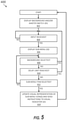
- Fig. 5 shows a flowchart of exemplary steps of a method 400 that may be taken using the system 300 to operate the communication system.
- the method 400 includes displaying background and/or the master switch 201.
- the display screen 10 may show a background image and the master switch 201.
- the method 400 includes checking for input received. As shown in Fig. 5 , step 404 may repeat until input is received such that the method 400 proceeds to step 406 where the sub-menu 202 is displayed. In step 408, the method 400 checks to determine if the background is selected and, if the background is selected, the process 400 returns to step 404. If the background is not selected, the process 400 moves to step 410 where the process checks to see if a delay limit has been reached. If the delay is reached before a sub-menu item is selected, the process 400 returns to step 404. When one of the sub-menu items is selected (step 412), the process 400 moves to step 414.
- a visual representation of a sub-menu icon is updated and a corresponding instruction is sent to the visual indicator 101. For example, if no mode for the visual indicator 101 was active before step 412, the icon (e.g. , 203-206) of the selected mode is illuminated or highlighted during step 414 ( e.g. , as shown in Fig. 3 ). In addition, an instruction is sent to activate the visual indicator 101 with the appropriate visual indicia. If one of the modes for the visual indicator 101 was active before step 412, when the process reaches step 414, either (a) the icon of the previously active mode is deactivated (if the active mode was selected - i.e.
- the sub-menu 202 will disappear from the display screen 10 after a set time interval after a mode has been activated/deactivated, while in other embodiments, the sub-menu 202 will remain on the screen until the passenger selects another object or portion of the display screen 10. In other embodiments, the sub-menu 202 will immediately disappear from the display screen 10 when a mode is selected.
- the components of the communication system may be formed of materials including, but not limited to, polyester, nylon, plastic, carbon composite, thermoplastic, aluminum, steel, other fabric materials, stainless steel, other plastic or polymer materials, other metallic materials, other composite materials, or other similar materials.
- suitable fasteners include, but are not limited to, screws, bolts, rivets or other mechanical or chemical fasteners.
Landscapes
- Engineering & Computer Science (AREA)
- Aviation & Aerospace Engineering (AREA)
- Illuminated Signs And Luminous Advertising (AREA)
- Management, Administration, Business Operations System, And Electronic Commerce (AREA)
- Audible And Visible Signals (AREA)
- Traffic Control Systems (AREA)
Description
- This application is related to and claims priority benefit from
U.S. Provisional Application No. 62/478,969 ("the '969 application"), filed on March 30, 2017 - The field of the invention relates to communication systems for passengers in seats for aircraft or the like.
- Arrangements of passenger seats, and particularly arrays of passenger seats in vehicles or aircraft, are designed to ensure passenger safety, comfort, and convenience along with maximizing efficiencies related to tasks within the cabin of the vehicle including for example, distributing objects to the passengers or responding to requests for assistance. In some instances, space in walkways/aisles of a vehicle cabin is limited due to standing passengers or airline products (such as beverage/meal carts). Conventional seats do not include any system for quickly identifying a plurality of statuses or conditions for a passenger of the seat. Flight attendants moving through the cabin of an aircraft may view visual indicators for each passenger, which will increase efficiency for typical airline tasks, expedite responses to medical concerns, and improve passenger experiences by limiting wait times and reducing unnecessary interruptions.
- In certain situations, it may be desirable to include a one-way communication system for a passenger seat that allows a passenger to provide notification of a status or condition such that the flight attendant can recognize the status without walking to the seat and/or without verbal communication with the passenger. [Insert page 1a]
- The invention is defined in appended claim 1.
- Embodiments of the invention covered by this patent are defined by the dependent claims below, not this summary. This summary is a high-level overview of various aspects of the invention and introduces some of the concepts that are further described in the Detailed Description section below. This summary is not intended to identify key or essential features Document
US2016/249073 describes a video display system for a passenger seat of a vehicle. The video display system is configured to be mounted to a seatback of each passenger seat or to other structure such that the system may be utilized by the passenger. The display system includes a video display assembly having a display housing configured to be mounted to structure in the vehicle. - Document
US2010/187354 describes an information system for an aircraft comprising an operating unit with input elements, a display unit arranged in the region of passenger accommodation, for displaying a message. The operating unit makes it possible to input a message from several selection options. of the claimed subject matter, nor is it intended to be used in isolation to determine the scope of the claimed subject matter. The subject matter should be understood by reference to appropriate portions of the entire specification of this patent, any or all drawings and each claim. - In some embodiments, the visual indicator displays a distinct visual indicia for each mode and the visual indicator comprises an LED light.
- In certain embodiments, the plurality of modes comprises a Do Not Disturb mode wherein the visual indicator illuminates as a solid red light.
- In some embodiments, the plurality of modes comprises a Wake Me for Meals/Beverage mode wherein the visual indicator illuminates as a solid blue light.
- The plurality of modes, in certain embodiments, comprises at least three of a Do Not Disturb mode, a Wake Me for Meals/Beverage mode, a Need Assistance mode, a Wake Me for Duty-Free mode, a Medical Emergency mode, and a Vacant Seat mode.
- In certain embodiments, the visual indicator is disposed on an upper surface of a seatback.
- The visual indicator, in certain embodiments, further comprises an auxiliary light disposed in a gap in the seatback.
-
-
Fig. 1 is a rear perspective view of a passenger seat according to certain embodiments of the present invention. -
Fig. 2 is a detail perspective view of the passenger seat ofFig. 1 . -
Figs. 3A, 3B , and3C are rear views of the passenger seat ofFig. 1 . -
Fig. 4 is a diagram of a computer apparatus according to certain embodiments of the present invention. -
Fig. 5 is a flowchart of an exemplary process performed by the computer apparatus ofFig. 4 . - The subject matter of embodiments of the present invention is described here with specificity to meet statutory requirements, but this description is not necessarily intended to limit the scope of the claims. The claimed subject matter may be embodied in other ways, may include different elements or steps, and may be used in conjunction with other existing or future technologies. This description should not be interpreted as implying any particular order or arrangement among or between various steps or elements except when the order of individual steps or arrangement of elements is explicitly described.
-
Figs. 1-3C illustrate embodiments ofpassenger seats 100 that include a communication system for each passenger. The communication system includes avisual indicator 101 and a control portion 200 where thevisual indicator 101 and the control portion 200 are electrically connected to one another. In some cases, thevisual indicator 101 is located on the top of thepassenger seat 100 immediately in front of the passenger. In other words, thevisual indicator 101 is disposed on a seatback located in front of a seated position for interfacing with the control portion 200. Thevisual indicator 101 may include a light, a small display screen, a combination thereof, or any other appropriate device. In some embodiments, thevisual indicator 101 is a light-emitting diode (LED) or an array of LEDs. Thevisual indicator 101 is configured to display multiple colors, optionally in combination with any of projected shapes/patterns, patterns of blinking lights, text, symbols, combinations thereof, or any other appropriate visual indicia. - As shown in
Figs. 1 and2 , thevisual indicator 101 may be located on an upper surface of aseatback 20 directly in front of the passenger that controls/operates the control portion 200. The communication system includes
adisplay screen 10 that is electrically connected to thevisual indicator 101. In addition, as shown inFig. 2 , thepassenger seat 100 may include anauxiliary light 11 in a gap between theseatback 20 and thedisplay screen 10. Theauxiliary light 11 may operate in addition to or in lieu of thevisual indicator 101. In some embodiments, theauxiliary light 11 operates independently of thevisual indicator 101. Thevisual indicator 101 may include a plurality of LED light sources, which allow thevisual indicator 101 to display a plurality of colors. - The
visual indicator 101 includes a plurality of modes. For example, in a first mode during a flight in an aircraft, a passenger may need to alert a flight attendant that he/she should not be disturbed for any reason (i.e., Do Not Disturb mode). Thevisual indicator 101 may include a second mode asking for the flight attendant to wake or alert the passenger for a meal/beverage being distributed by the airline (i.e., Wake Me for Meals/Beverage mode). Thevisual indicator 101 may include a third mode asking for the flight attendant to wake or alert the passenger for duty-free products being sold in the aircraft (i.e., Wake Me for Duty-Free mode). Thevisual indicator 101 may include a fourth mode asking for the flight attendant for assistance (i.e., Need Assistance mode). Thevisual indicator 101 may include a fifth mode asking for immediate medical attention (i.e., Medical Emergency mode). Thevisual indicator 101 may include a sixth mode to indicate to other passengers and/or flight attendants that the seat is vacant (i.e., Vacant Seat mode). Although six modes are described above, alternative and/or additional modes may be included. - The Do Not Disturb mode (the first mode) is represented by a color, and optionally a symbol, a blinking pattern, a combination thereof, or any other appropriate indicator. For example, the
visual indicator 101 may illuminate a solid yellow or red color (or any other color). In some embodiments, thevisual indicator 101 may illuminate a solid color with a single horizontal or diagonal line (or a pair of diagonal lines forming an "X"). The line(s) may be black, white, and/or any other appropriate color. In some embodiments, thevisual indicator 101 may blink showing a solid color, a solid color with at least one line (as described above), or may alternate between these representations (or may alternate with other appropriate representations). - The Wake Me for Meals/Beverage mode (the second mode) is represented by a color, and optionally a symbol, a blinking pattern, a combination thereof, or any other appropriate indicator. For example, the
visual indicator 101 may illuminate a solid blue color (or any other color). In some embodiments, thevisual indicator 101 may illuminate a solid color with a symbol of a fork and/or a knife. In some embodiments, thevisual indicator 101 may blink showing a solid color, a solid color with a symbol of a fork and/or a knife (as described above), or may alternate between these representations (or may alternate with other appropriate representations). - The Wake Me for Duty-Free mode (the third mode) is represented by a color, and optionally a symbol, a blinking pattern, a combination thereof, or any other appropriate indicator. For example, the
visual indicator 101 may illuminate a solid green color (or any other color). In some embodiments, thevisual indicator 101 may illuminate a solid color with a currency symbol and/or a symbol of a bottle. In some embodiments, thevisual indicator 101 may blink showing a solid color, a solid color with a currency symbol and/or a symbol of a bottle (as described above), or may alternate between these representations (or may alternate with other appropriate representations). - The Need Assistance mode (the fourth mode) is way represented by a color, and optionally a symbol, a blinking pattern, a combination thereof, or any other appropriate indicator. For example, the
visual indicator 101 may illuminate a solid purple color (or any other color). In some embodiments, thevisual indicator 101 may illuminate a solid color with a symbol such as a question mark. In some embodiments, thevisual indicator 101 may blink showing a solid color, a solid color with a question mark (as described above), or may alternate between these representations (or may alternate with other appropriate representations). - The Medical Emergency mode (the fifth mode) is represented by a color, and optionally a symbol, a blinking pattern, a combination thereof, or any other appropriate indicator. For example, the
visual indicator 101 may illuminate a solid red color (or any other color). In some embodiments, thevisual indicator 101 may illuminate a solid color with a symbol such as the Star of Life or a red cross ("+") symbol. In some embodiments, thevisual indicator 101 may blink showing a solid color, a solid color with a symbol such as the Star of Life or a red cross ("+") symbol (as described above), or may alternate between these representations (or may alternate with other appropriate representations). In some embodiments, the fifth mode may include a rapid or strobe blinking pattern. - The Vacant Seat mode (the sixth mode) is represented by a color, and optionally a symbol, a blinking pattern, a combination thereof, or any other appropriate indicator. For example, the
visual indicator 101 may illuminate a solid white color (or any other color). In some embodiments, thevisual indicator 101 may illuminate a solid color with a symbol such as "Ø" or "{}". In some embodiments, thevisual indicator 101 may blink showing a solid color, a symbol such as "Ø" or "{}" (as described above), or may alternate between these representations (or may alternate with other appropriate representations). - As shown in
Figs. 3A-3C , the communication system includes a control portion 200 which includes amaster switch 201 that is on thedisplay screen 10. Themaster switch 201 is an icon on thedisplay screen 10 and is configured to open a sub-menu 202 on thedisplay screen 10. As shown inFig. 3B , thesub-menu 202 includes icons for a plurality of modes of thevisual indicator 101.Fig. 3B shows icons 203-206, but the sub-menu 202 may include any number of icons for various modes including, but not limited to, the six modes described above. In some cases, thesub-menu 202 may be customizable by the airline and/or the individual passenger such that the sub-menu 202 may include more or fewer icons. -
Fig. 3B shows one example of the sub-menu 202 that includes afirst icon 203 for the Do Not Disturb mode, asecond icon 204 for the Wake Me for Meals/Beverage mode, athird icon 205 for the Wake Me for Duty-Free mode, and afourth icon 206 for the Need Assistance mode. The sub-menu 202 can be controlled/manipulated via a touchscreen interface. -
Fig. 3C illustrates one example of the sub-menu 202 where one of the modes has been activated. In some embodiments, as shown inFig. 3C , the portion of thesub-menu 202 surrounding thesecond icon 204 is illuminated or highlighted to indicate that the Wake Me for Meals/Beverage mode has been selected. Thevisual indicator 101 is activated with the appropriate visual indicia. In some embodiments, thesub-menu 202 will disappear from thedisplay screen 10 after a set time interval after a mode has been selected, while in other embodiments, thesub-menu 202 will remain on the screen until the passenger selects another object or portion of thedisplay screen 10. In other embodiments, thesub-menu 202 will immediately disappear from thedisplay screen 10 when a mode is selected. -
Fig. 4 illustrates aninterface system 300. In some aspects, theinterface system 300 may be used with the communication system; however, in various other examples, theinterface system 300 may be used with various other types of devices. - In some embodiments, the functions and processes of one or more components of the
system 300 to facilitate communication, such as the processes illustrated inFig. 5 and described below, can be implemented by computer program instructions. - The functions of one or more of the components can be implemented by computer program instructions. These computer program instructions can be provided to a processor of a general purpose computer, special purpose computer, and/or other programmable data processing apparatus to produce a machine, such that the instructions, which execute via the processor of the computer and/or other programmable data processing apparatus, create a mechanism for implementing the functions of the components specified in the block diagrams. These computer program instructions can also be stored in a non-transitory computer-readable memory that can direct a computer or other programmable data processing apparatus to function in a particular manner, such that the instructions stored in the non-transitory computer-readable memory produce an article of manufacture including instructions, which implement the function specified in the block diagrams and associated description. The computer program instructions can also be loaded onto a computer or other programmable data processing apparatus to cause a series of operational steps to be performed on the computer or other programmable apparatus to produce a computer-implemented process such that the instructions that execute on the computer or other programmable apparatus provide steps for implementing the functions of the components specified in the block diagrams and the associated description.
- Accordingly, the
system 300 described herein can be embodied at least in part in hardware and/or in software (including firmware, resident software, micro-code, etc.). Furthermore, aspects of thesystem 300 can take the form of a computer program product on a computer-usable or computer-readable storage medium having computer-usable or computer-readable program code embodied in the medium for use by or in connection with an instruction execution system. A computer-usable or computer-readable medium can be any non-transitory medium that is not a transitory signal and can contain or store the program for use by or in connection with the instruction or execution of a system, apparatus, or device. The computer-usable or computer-readable medium can be, for example but not limited to, an electronic, magnetic, optical, electromagnetic, infrared, or semiconductor system, apparatus or device. More specific examples (a non-exhaustive list) of the computer-readable medium can include the following: a portable computer diskette; a random access memory; a read-only memory; an erasable programmable read-only memory (or Flash memory); and a portable compact disc read-only memory. -
Fig. 4 is a diagram of acomputer apparatus 300 according to some embodiments. The various participants and elements may use any suitable number of subsystems in thecomputer apparatus 300 to facilitate the functions described herein. Examples of such subsystems or components are shown inFig. 4 . The subsystems shown inFig. 4 may be interconnected via asystem bus 310. Additional subsystems such as akeyboard 330,input device 335, a fixed disk 340 (or other memory comprising computer-readable media),display screen 10, which is coupled todisplay adapter 360, and others are shown. In various examples, these and other various user interfaces may be configured to receive inputs from the passenger/user, such as a desired mode for thevisual indicator 101. Various other inputs and outputs may be provided through the user interfaces. Thekeyboard 330 may be an external device or may be a virtual keyboard displayed on a touchscreen surface (e.g., display screen 10). Theinput device 335 may bemaster switch 201 or any other appropriate input. - Peripherals and input/output (I/O) devices (not shown), which couple to I/
O controller 370, can be connected to the computer system by any number of means known in the art, such asserial port 380. For example,serial port 380 orexternal interface 385 can be used to connect thecomputer apparatus 300 to a wide area network such as the Internet, a mouse input device, or a scanner. The interconnection via system bus allows thecentral processor 390 to communicate with each subsystem and to control the execution of instructions fromsystem memory 395 or the fixeddisk 340, as well as the exchange of information between subsystems. Thesystem memory 395 and/or the fixeddisk 340 may embody a computer-readable medium. - The software components or functions described in this application may be implemented as software code to be executed by one or more processors using any suitable computer language such as, for example, Java, C++, Fortran, C, or Perl using, for example, conventional or object-oriented techniques. The software code may be stored as a series of instructions, or commands on a computer-readable medium, such as a random access memory (RAM), a read-only memory (ROM), a magnetic medium such as a hard-drive or a floppy disk, or an optical medium such as a CD-ROM. Any such computer-readable medium may also reside on or within a single computational apparatus, and may be present on or within different computational apparatuses within a system or network.
- The invention can be implemented in the form of control logic in software or hardware or a combination of both. The control logic may be stored in an information storage medium as a plurality of instructions adapted to direct an information-processing device to perform a set of steps disclosed in embodiments of the invention. Based on the disclosure and teachings provided herein, a person of ordinary skill in the art will appreciate other ways and/or methods to implement the invention. In embodiments, any of the entities described herein may be embodied by a computer that performs any or all of the functions and steps disclosed.
-
Fig. 5 shows a flowchart of exemplary steps of amethod 400 that may be taken using thesystem 300 to operate the communication system. In one aspect, instep 402, themethod 400 includes displaying background and/or themaster switch 201. For example, thedisplay screen 10 may show a background image and themaster switch 201. - In some embodiments, in a
step 404, themethod 400 includes checking for input received. As shown inFig. 5 , step 404 may repeat until input is received such that themethod 400 proceeds to step 406 where thesub-menu 202 is displayed. Instep 408, themethod 400 checks to determine if the background is selected and, if the background is selected, theprocess 400 returns to step 404. If the background is not selected, theprocess 400 moves to step 410 where the process checks to see if a delay limit has been reached. If the delay is reached before a sub-menu item is selected, theprocess 400 returns to step 404. When one of the sub-menu items is selected (step 412), theprocess 400 moves to step 414. In step 414, a visual representation of a sub-menu icon is updated and a corresponding instruction is sent to thevisual indicator 101. For example, if no mode for thevisual indicator 101 was active beforestep 412, the icon (e.g., 203-206) of the selected mode is illuminated or highlighted during step 414 (e.g., as shown inFig. 3 ). In addition, an instruction is sent to activate thevisual indicator 101 with the appropriate visual indicia. If one of the modes for thevisual indicator 101 was active beforestep 412, when the process reaches step 414, either (a) the icon of the previously active mode is deactivated (if the active mode was selected - i.e., to turn off the active mode) or (b) the icon for a newly selected mode is illuminated or highlighted (e.g., as shown inFig. 3 ) while simultaneously, the icon for the previously active is deactivated. In addition, an instruction is sent to either (a) deactivate the visual indicator 101 (b) change thevisual indicator 101 from the previously active mode to the newly selected mode with the appropriate visual indicia. Although not illustrated inFig. 5 , in some embodiments, there may be a delay in theprocess 400 after step 414 before the sub-menu 202 disappears and the process returns to step 402. After step 414, as described above, in some embodiments, thesub-menu 202 will disappear from thedisplay screen 10 after a set time interval after a mode has been activated/deactivated, while in other embodiments, thesub-menu 202 will remain on the screen until the passenger selects another object or portion of thedisplay screen 10. In other embodiments, thesub-menu 202 will immediately disappear from thedisplay screen 10 when a mode is selected. - The components of the communication system may be formed of materials including, but not limited to, polyester, nylon, plastic, carbon composite, thermoplastic, aluminum, steel, other fabric materials, stainless steel, other plastic or polymer materials, other metallic materials, other composite materials, or other similar materials. Moreover, the components of the communication system may be attached to one another via suitable fasteners, which include, but are not limited to, screws, bolts, rivets or other mechanical or chemical fasteners.
- Different arrangements of the components depicted in the drawings or described above, as well as components and steps not shown or described are possible. Similarly, some features and sub-combinations are useful and may be employed without reference to other features and sub-combinations. Embodiments of the invention have been described for illustrative and not restrictive purposes, and alternative embodiments will become apparent to readers of this patent. Accordingly, the present invention is not limited to the embodiments described above or depicted in the drawings, and various embodiments and modifications may be made without departing from the scope of the claims below.
Claims (8)
- A communication system for a vehicle seat, the communication system comprising:a visual indicator (101) comprising a lighting mechanism configured to display a plurality of colors;a control portion (200) electrically connected to the visual indicator (101); anda plurality of modes, wherein:characterized in that the communication system further comprises a display screen (10), wherein the control portion (200) comprises a master switch (201) to open a sub-menu on the display screen (10), wherein the master switch (201) is an icon on the display screen (10), and the sub-menu (202) illustrates at least two of the plurality of modes on the display screen (10), the sub-menu (202) including icons for a plurality of modes of the visual indicator (101), the sub-menu (202) being controllable via a touchscreen interface.each mode is associated with one of the plurality of colors; andselection of one of the plurality of modes causes the control portion (200) to signal the lighting mechanism to display the color associated with the selected mode,
- The communication system of claim 1, wherein the visual indicator (101) displays a distinct visual indicia for each mode and the visual indicator (101) comprises an LED light.
- The communication system of claim 1, wherein the plurality of modes comprises a Do Not Disturb mode wherein the visual indicator (101) illuminates as a solid red light.
- The communication system of claim 1, wherein the plurality of modes comprises a Wake Me for Meals/Beverage mode wherein the visual indicator (101) illuminates as a solid blue light.
- The communication system of claim 1, wherein the plurality of modes comprises at least three of a Do Not Disturb mode, a Wake Me for Meals/Beverage mode, a Need Assistance mode, a Wake Me for Duty-Free mode, a Medical Emergency mode, and a Vacant Seat mode.
- The communication system of claim 1, wherein the visual indicator (101) is disposed on an upper surface of a seatback (20).
- The communication system of claim 6, wherein the visual indicator (101) further comprises an auxiliary light (11) disposed in a gap in the seatback (20).
- A passenger seat (100) for an aircraft comprising a communication system according to any of the claims 1 to 7.
Applications Claiming Priority (2)
| Application Number | Priority Date | Filing Date | Title |
|---|---|---|---|
| US201762478969P | 2017-03-30 | 2017-03-30 | |
| PCT/US2018/025363 WO2018183820A1 (en) | 2017-03-30 | 2018-03-30 | Passenger communication system |
Publications (2)
| Publication Number | Publication Date |
|---|---|
| EP3601047A1 EP3601047A1 (en) | 2020-02-05 |
| EP3601047B1 true EP3601047B1 (en) | 2022-03-02 |
Family
ID=62002735
Family Applications (1)
| Application Number | Title | Priority Date | Filing Date |
|---|---|---|---|
| EP18718566.5A Active EP3601047B1 (en) | 2017-03-30 | 2018-03-30 | Passenger communication system |
Country Status (4)
| Country | Link |
|---|---|
| US (1) | US10800543B2 (en) |
| EP (1) | EP3601047B1 (en) |
| CN (1) | CN110520359B (en) |
| WO (1) | WO2018183820A1 (en) |
Families Citing this family (5)
| Publication number | Priority date | Publication date | Assignee | Title |
|---|---|---|---|---|
| DE102018115899A1 (en) | 2018-06-30 | 2020-01-02 | Airbus Operations Gmbh | Aircraft seat assembly and aircraft with an aircraft seat assembly |
| DE102018115900A1 (en) * | 2018-06-30 | 2020-01-02 | Airbus Operations Gmbh | Aircraft seat, aircraft seat arrangement with an aircraft seat and aircraft with an aircraft seat arrangement |
| US20200262559A1 (en) * | 2019-02-20 | 2020-08-20 | Goodrich Corporation | Service light integrated with reading light switch |
| DE102021117764B4 (en) * | 2021-07-09 | 2025-03-20 | Audi Aktiengesellschaft | HEADREST WITH A NOISE CANCELLING DEVICE AND VEHICLE SEAT |
| US20260028123A1 (en) * | 2024-07-24 | 2026-01-29 | B/E Aerospace, Inc. | Aircraft seatback tray table module |
Family Cites Families (8)
| Publication number | Priority date | Publication date | Assignee | Title |
|---|---|---|---|---|
| DE20013822U1 (en) * | 2000-08-10 | 2000-12-14 | Braun, Maria, 81547 München | Eye covering |
| DE10329752A1 (en) * | 2003-07-02 | 2005-02-03 | Airbus Deutschland Gmbh | System for guiding a passenger in the cabin of an aircraft |
| DE102008059823B4 (en) * | 2008-12-01 | 2012-08-30 | Airbus Operations Gmbh | Information system for messages from passengers to cabin crew |
| WO2012078501A2 (en) * | 2010-12-07 | 2012-06-14 | Weber Aircraft Llc | Display assembly with lighting apparatus |
| DE202011100795U1 (en) * | 2011-05-15 | 2011-10-25 | Heiko Herrmann | Head rest for relaxed sleeping while sitting |
| CA2940416A1 (en) * | 2014-02-28 | 2015-09-03 | Bombardier Inc. | Method, system, and executable program product for controlling passenger services |
| US10219059B2 (en) * | 2014-09-29 | 2019-02-26 | B/E Aerospace, Inc. | Smart passenger service unit |
| US9788021B2 (en) * | 2015-02-20 | 2017-10-10 | Panasonic Avionics Corporation | Display system for a vehicle entertainment system |
-
2018
- 2018-03-30 WO PCT/US2018/025363 patent/WO2018183820A1/en not_active Ceased
- 2018-03-30 US US16/489,979 patent/US10800543B2/en active Active
- 2018-03-30 CN CN201880022928.6A patent/CN110520359B/en active Active
- 2018-03-30 EP EP18718566.5A patent/EP3601047B1/en active Active
Also Published As
| Publication number | Publication date |
|---|---|
| CN110520359A (en) | 2019-11-29 |
| CN110520359B (en) | 2023-07-14 |
| EP3601047A1 (en) | 2020-02-05 |
| US20200002023A1 (en) | 2020-01-02 |
| WO2018183820A1 (en) | 2018-10-04 |
| US10800543B2 (en) | 2020-10-13 |
Similar Documents
| Publication | Publication Date | Title |
|---|---|---|
| US10800543B2 (en) | Passenger communication system | |
| US10237511B2 (en) | Projection information display | |
| EP2915700A2 (en) | LED strip lighting device for a cabin of a passenger aircraft | |
| JP7840632B2 (en) | Seat assembly, seat belt fastening system, and method | |
| CN110466776B (en) | Integrated passenger service unit and system thereof | |
| US20170029113A1 (en) | Passenger Service Unit and Related Systems | |
| US20250353612A1 (en) | Methods and systems for lighting a vertical take-off and landing vehicle | |
| US9205914B1 (en) | Distributed architecture for a system and a method of operation of the system incorporating a graphical user interface controlling functions in a vehicle cabin | |
| US20040195875A1 (en) | Reclining passenger seat having a visual seat position indicator | |
| US20090112407A1 (en) | System and Method for Communication by Architecture | |
| EP3378785B1 (en) | Carpet display systems and methods | |
| US20100187354A1 (en) | Information system for messages from passengers to the cabin crew | |
| EP3546355B1 (en) | Aircraft area having a textile display, and an aircraft including such an aircraft area | |
| EP4177164B1 (en) | Seat assembly having integrated lighting system | |
| US10822088B2 (en) | Unified passenger service unit (PSU) control | |
| CN111284715B (en) | Unit alarm system and method for mobile platform | |
| US20230335138A1 (en) | Onboard aircraft system with artificial human interface to assist passengers and/or crew members | |
| CN113226930A (en) | Passenger positioning platform | |
| EP2939924A1 (en) | Digital crew assist | |
| US9327146B2 (en) | Cabin service arrangement, fuselage of an aircraft, a method of effecting a cabin attendant call | |
| US9481463B2 (en) | Panel and system for aircraft cabin management | |
| JP2010140394A (en) | Bus location system, and display device | |
| US10135927B1 (en) | ARINC 661 display system and methods incorporating non-ARINC 661 protocols | |
| EP4180330A1 (en) | Systems and methods for touchless passenger light control | |
| JP2015187703A (en) | Display device |
Legal Events
| Date | Code | Title | Description |
|---|---|---|---|
| STAA | Information on the status of an ep patent application or granted ep patent |
Free format text: STATUS: UNKNOWN |
|
| STAA | Information on the status of an ep patent application or granted ep patent |
Free format text: STATUS: THE INTERNATIONAL PUBLICATION HAS BEEN MADE |
|
| PUAI | Public reference made under article 153(3) epc to a published international application that has entered the european phase |
Free format text: ORIGINAL CODE: 0009012 |
|
| STAA | Information on the status of an ep patent application or granted ep patent |
Free format text: STATUS: REQUEST FOR EXAMINATION WAS MADE |
|
| 17P | Request for examination filed |
Effective date: 20190916 |
|
| AK | Designated contracting states |
Kind code of ref document: A1 Designated state(s): AL AT BE BG CH CY CZ DE DK EE ES FI FR GB GR HR HU IE IS IT LI LT LU LV MC MK MT NL NO PL PT RO RS SE SI SK SM TR |
|
| AX | Request for extension of the european patent |
Extension state: BA ME |
|
| DAV | Request for validation of the european patent (deleted) | ||
| DAX | Request for extension of the european patent (deleted) | ||
| GRAP | Despatch of communication of intention to grant a patent |
Free format text: ORIGINAL CODE: EPIDOSNIGR1 |
|
| STAA | Information on the status of an ep patent application or granted ep patent |
Free format text: STATUS: GRANT OF PATENT IS INTENDED |
|
| INTG | Intention to grant announced |
Effective date: 20211001 |
|
| GRAS | Grant fee paid |
Free format text: ORIGINAL CODE: EPIDOSNIGR3 |
|
| GRAA | (expected) grant |
Free format text: ORIGINAL CODE: 0009210 |
|
| STAA | Information on the status of an ep patent application or granted ep patent |
Free format text: STATUS: THE PATENT HAS BEEN GRANTED |
|
| AK | Designated contracting states |
Kind code of ref document: B1 Designated state(s): AL AT BE BG CH CY CZ DE DK EE ES FI FR GB GR HR HU IE IS IT LI LT LU LV MC MK MT NL NO PL PT RO RS SE SI SK SM TR |
|
| REG | Reference to a national code |
Ref country code: GB Ref legal event code: FG4D |
|
| REG | Reference to a national code |
Ref country code: CH Ref legal event code: EP Ref country code: AT Ref legal event code: REF Ref document number: 1472058 Country of ref document: AT Kind code of ref document: T Effective date: 20220315 |
|
| REG | Reference to a national code |
Ref country code: DE Ref legal event code: R096 Ref document number: 602018031575 Country of ref document: DE |
|
| REG | Reference to a national code |
Ref country code: IE Ref legal event code: FG4D |
|
| REG | Reference to a national code |
Ref country code: LT Ref legal event code: MG9D |
|
| REG | Reference to a national code |
Ref country code: NL Ref legal event code: MP Effective date: 20220302 |
|
| PG25 | Lapsed in a contracting state [announced via postgrant information from national office to epo] |
Ref country code: SE Free format text: LAPSE BECAUSE OF FAILURE TO SUBMIT A TRANSLATION OF THE DESCRIPTION OR TO PAY THE FEE WITHIN THE PRESCRIBED TIME-LIMIT Effective date: 20220302 Ref country code: RS Free format text: LAPSE BECAUSE OF FAILURE TO SUBMIT A TRANSLATION OF THE DESCRIPTION OR TO PAY THE FEE WITHIN THE PRESCRIBED TIME-LIMIT Effective date: 20220302 Ref country code: NO Free format text: LAPSE BECAUSE OF FAILURE TO SUBMIT A TRANSLATION OF THE DESCRIPTION OR TO PAY THE FEE WITHIN THE PRESCRIBED TIME-LIMIT Effective date: 20220602 Ref country code: LT Free format text: LAPSE BECAUSE OF FAILURE TO SUBMIT A TRANSLATION OF THE DESCRIPTION OR TO PAY THE FEE WITHIN THE PRESCRIBED TIME-LIMIT Effective date: 20220302 Ref country code: HR Free format text: LAPSE BECAUSE OF FAILURE TO SUBMIT A TRANSLATION OF THE DESCRIPTION OR TO PAY THE FEE WITHIN THE PRESCRIBED TIME-LIMIT Effective date: 20220302 Ref country code: ES Free format text: LAPSE BECAUSE OF FAILURE TO SUBMIT A TRANSLATION OF THE DESCRIPTION OR TO PAY THE FEE WITHIN THE PRESCRIBED TIME-LIMIT Effective date: 20220302 Ref country code: BG Free format text: LAPSE BECAUSE OF FAILURE TO SUBMIT A TRANSLATION OF THE DESCRIPTION OR TO PAY THE FEE WITHIN THE PRESCRIBED TIME-LIMIT Effective date: 20220602 |
|
| REG | Reference to a national code |
Ref country code: AT Ref legal event code: MK05 Ref document number: 1472058 Country of ref document: AT Kind code of ref document: T Effective date: 20220302 |
|
| PG25 | Lapsed in a contracting state [announced via postgrant information from national office to epo] |
Ref country code: PL Free format text: LAPSE BECAUSE OF FAILURE TO SUBMIT A TRANSLATION OF THE DESCRIPTION OR TO PAY THE FEE WITHIN THE PRESCRIBED TIME-LIMIT Effective date: 20220302 Ref country code: LV Free format text: LAPSE BECAUSE OF FAILURE TO SUBMIT A TRANSLATION OF THE DESCRIPTION OR TO PAY THE FEE WITHIN THE PRESCRIBED TIME-LIMIT Effective date: 20220302 Ref country code: GR Free format text: LAPSE BECAUSE OF FAILURE TO SUBMIT A TRANSLATION OF THE DESCRIPTION OR TO PAY THE FEE WITHIN THE PRESCRIBED TIME-LIMIT Effective date: 20220603 Ref country code: FI Free format text: LAPSE BECAUSE OF FAILURE TO SUBMIT A TRANSLATION OF THE DESCRIPTION OR TO PAY THE FEE WITHIN THE PRESCRIBED TIME-LIMIT Effective date: 20220302 |
|
| PG25 | Lapsed in a contracting state [announced via postgrant information from national office to epo] |
Ref country code: NL Free format text: LAPSE BECAUSE OF FAILURE TO SUBMIT A TRANSLATION OF THE DESCRIPTION OR TO PAY THE FEE WITHIN THE PRESCRIBED TIME-LIMIT Effective date: 20220302 |
|
| PG25 | Lapsed in a contracting state [announced via postgrant information from national office to epo] |
Ref country code: SM Free format text: LAPSE BECAUSE OF FAILURE TO SUBMIT A TRANSLATION OF THE DESCRIPTION OR TO PAY THE FEE WITHIN THE PRESCRIBED TIME-LIMIT Effective date: 20220302 Ref country code: SK Free format text: LAPSE BECAUSE OF FAILURE TO SUBMIT A TRANSLATION OF THE DESCRIPTION OR TO PAY THE FEE WITHIN THE PRESCRIBED TIME-LIMIT Effective date: 20220302 Ref country code: RO Free format text: LAPSE BECAUSE OF FAILURE TO SUBMIT A TRANSLATION OF THE DESCRIPTION OR TO PAY THE FEE WITHIN THE PRESCRIBED TIME-LIMIT Effective date: 20220302 Ref country code: PT Free format text: LAPSE BECAUSE OF FAILURE TO SUBMIT A TRANSLATION OF THE DESCRIPTION OR TO PAY THE FEE WITHIN THE PRESCRIBED TIME-LIMIT Effective date: 20220704 Ref country code: EE Free format text: LAPSE BECAUSE OF FAILURE TO SUBMIT A TRANSLATION OF THE DESCRIPTION OR TO PAY THE FEE WITHIN THE PRESCRIBED TIME-LIMIT Effective date: 20220302 Ref country code: CZ Free format text: LAPSE BECAUSE OF FAILURE TO SUBMIT A TRANSLATION OF THE DESCRIPTION OR TO PAY THE FEE WITHIN THE PRESCRIBED TIME-LIMIT Effective date: 20220302 Ref country code: AT Free format text: LAPSE BECAUSE OF FAILURE TO SUBMIT A TRANSLATION OF THE DESCRIPTION OR TO PAY THE FEE WITHIN THE PRESCRIBED TIME-LIMIT Effective date: 20220302 |
|
| REG | Reference to a national code |
Ref country code: CH Ref legal event code: PL |
|
| PG25 | Lapsed in a contracting state [announced via postgrant information from national office to epo] |
Ref country code: IS Free format text: LAPSE BECAUSE OF FAILURE TO SUBMIT A TRANSLATION OF THE DESCRIPTION OR TO PAY THE FEE WITHIN THE PRESCRIBED TIME-LIMIT Effective date: 20220702 Ref country code: AL Free format text: LAPSE BECAUSE OF FAILURE TO SUBMIT A TRANSLATION OF THE DESCRIPTION OR TO PAY THE FEE WITHIN THE PRESCRIBED TIME-LIMIT Effective date: 20220302 |
|
| REG | Reference to a national code |
Ref country code: DE Ref legal event code: R097 Ref document number: 602018031575 Country of ref document: DE |
|
| REG | Reference to a national code |
Ref country code: BE Ref legal event code: MM Effective date: 20220331 |
|
| PLBE | No opposition filed within time limit |
Free format text: ORIGINAL CODE: 0009261 |
|
| STAA | Information on the status of an ep patent application or granted ep patent |
Free format text: STATUS: NO OPPOSITION FILED WITHIN TIME LIMIT |
|
| PG25 | Lapsed in a contracting state [announced via postgrant information from national office to epo] |
Ref country code: MC Free format text: LAPSE BECAUSE OF FAILURE TO SUBMIT A TRANSLATION OF THE DESCRIPTION OR TO PAY THE FEE WITHIN THE PRESCRIBED TIME-LIMIT Effective date: 20220302 Ref country code: LU Free format text: LAPSE BECAUSE OF NON-PAYMENT OF DUE FEES Effective date: 20220330 Ref country code: LI Free format text: LAPSE BECAUSE OF NON-PAYMENT OF DUE FEES Effective date: 20220331 Ref country code: IE Free format text: LAPSE BECAUSE OF NON-PAYMENT OF DUE FEES Effective date: 20220330 Ref country code: DK Free format text: LAPSE BECAUSE OF FAILURE TO SUBMIT A TRANSLATION OF THE DESCRIPTION OR TO PAY THE FEE WITHIN THE PRESCRIBED TIME-LIMIT Effective date: 20220302 Ref country code: CH Free format text: LAPSE BECAUSE OF NON-PAYMENT OF DUE FEES Effective date: 20220331 |
|
| 26N | No opposition filed |
Effective date: 20221205 |
|
| PG25 | Lapsed in a contracting state [announced via postgrant information from national office to epo] |
Ref country code: SI Free format text: LAPSE BECAUSE OF FAILURE TO SUBMIT A TRANSLATION OF THE DESCRIPTION OR TO PAY THE FEE WITHIN THE PRESCRIBED TIME-LIMIT Effective date: 20220302 Ref country code: BE Free format text: LAPSE BECAUSE OF NON-PAYMENT OF DUE FEES Effective date: 20220331 |
|
| PG25 | Lapsed in a contracting state [announced via postgrant information from national office to epo] |
Ref country code: IT Free format text: LAPSE BECAUSE OF FAILURE TO SUBMIT A TRANSLATION OF THE DESCRIPTION OR TO PAY THE FEE WITHIN THE PRESCRIBED TIME-LIMIT Effective date: 20220302 |
|
| PG25 | Lapsed in a contracting state [announced via postgrant information from national office to epo] |
Ref country code: MK Free format text: LAPSE BECAUSE OF FAILURE TO SUBMIT A TRANSLATION OF THE DESCRIPTION OR TO PAY THE FEE WITHIN THE PRESCRIBED TIME-LIMIT Effective date: 20220302 Ref country code: CY Free format text: LAPSE BECAUSE OF FAILURE TO SUBMIT A TRANSLATION OF THE DESCRIPTION OR TO PAY THE FEE WITHIN THE PRESCRIBED TIME-LIMIT Effective date: 20220302 |
|
| PG25 | Lapsed in a contracting state [announced via postgrant information from national office to epo] |
Ref country code: HU Free format text: LAPSE BECAUSE OF FAILURE TO SUBMIT A TRANSLATION OF THE DESCRIPTION OR TO PAY THE FEE WITHIN THE PRESCRIBED TIME-LIMIT; INVALID AB INITIO Effective date: 20180330 |
|
| PG25 | Lapsed in a contracting state [announced via postgrant information from national office to epo] |
Ref country code: TR Free format text: LAPSE BECAUSE OF FAILURE TO SUBMIT A TRANSLATION OF THE DESCRIPTION OR TO PAY THE FEE WITHIN THE PRESCRIBED TIME-LIMIT Effective date: 20220302 |
|
| PG25 | Lapsed in a contracting state [announced via postgrant information from national office to epo] |
Ref country code: MT Free format text: LAPSE BECAUSE OF FAILURE TO SUBMIT A TRANSLATION OF THE DESCRIPTION OR TO PAY THE FEE WITHIN THE PRESCRIBED TIME-LIMIT Effective date: 20220302 |
|
| PGFP | Annual fee paid to national office [announced via postgrant information from national office to epo] |
Ref country code: DE Payment date: 20250218 Year of fee payment: 8 |
|
| PGFP | Annual fee paid to national office [announced via postgrant information from national office to epo] |
Ref country code: FR Payment date: 20250219 Year of fee payment: 8 |
|
| PGFP | Annual fee paid to national office [announced via postgrant information from national office to epo] |
Ref country code: GB Payment date: 20260324 Year of fee payment: 9 |