EP3600919B1 - Variable oscillation three dimensional sipe - Google Patents
Variable oscillation three dimensional sipe Download PDFInfo
- Publication number
- EP3600919B1 EP3600919B1 EP18776170.5A EP18776170A EP3600919B1 EP 3600919 B1 EP3600919 B1 EP 3600919B1 EP 18776170 A EP18776170 A EP 18776170A EP 3600919 B1 EP3600919 B1 EP 3600919B1
- Authority
- EP
- European Patent Office
- Prior art keywords
- tread
- sipe
- dimensional
- tire
- pattern
- Prior art date
- Legal status (The legal status is an assumption and is not a legal conclusion. Google has not performed a legal analysis and makes no representation as to the accuracy of the status listed.)
- Active
Links
Images




Classifications
-
- B—PERFORMING OPERATIONS; TRANSPORTING
- B60—VEHICLES IN GENERAL
- B60C—VEHICLE TYRES; TYRE INFLATION; TYRE CHANGING; CONNECTING VALVES TO INFLATABLE ELASTIC BODIES IN GENERAL; DEVICES OR ARRANGEMENTS RELATED TO TYRES
- B60C11/00—Tyre tread bands; Tread patterns; Anti-skid inserts
- B60C11/03—Tread patterns
- B60C11/12—Tread patterns characterised by the use of narrow slits or incisions, e.g. sipes
- B60C11/1204—Tread patterns characterised by the use of narrow slits or incisions, e.g. sipes with special shape of the sipe
- B60C11/1218—Three-dimensional shape with regard to depth and extending direction
-
- B—PERFORMING OPERATIONS; TRANSPORTING
- B60—VEHICLES IN GENERAL
- B60C—VEHICLE TYRES; TYRE INFLATION; TYRE CHANGING; CONNECTING VALVES TO INFLATABLE ELASTIC BODIES IN GENERAL; DEVICES OR ARRANGEMENTS RELATED TO TYRES
- B60C11/00—Tyre tread bands; Tread patterns; Anti-skid inserts
- B60C11/03—Tread patterns
- B60C11/04—Tread patterns in which the raised area of the pattern consists only of continuous circumferential ribs, e.g. zig-zag
-
- B—PERFORMING OPERATIONS; TRANSPORTING
- B60—VEHICLES IN GENERAL
- B60C—VEHICLE TYRES; TYRE INFLATION; TYRE CHANGING; CONNECTING VALVES TO INFLATABLE ELASTIC BODIES IN GENERAL; DEVICES OR ARRANGEMENTS RELATED TO TYRES
- B60C11/00—Tyre tread bands; Tread patterns; Anti-skid inserts
- B60C11/03—Tread patterns
- B60C11/12—Tread patterns characterised by the use of narrow slits or incisions, e.g. sipes
- B60C11/1259—Depth of the sipe
-
- B—PERFORMING OPERATIONS; TRANSPORTING
- B60—VEHICLES IN GENERAL
- B60C—VEHICLE TYRES; TYRE INFLATION; TYRE CHANGING; CONNECTING VALVES TO INFLATABLE ELASTIC BODIES IN GENERAL; DEVICES OR ARRANGEMENTS RELATED TO TYRES
- B60C11/00—Tyre tread bands; Tread patterns; Anti-skid inserts
- B60C11/03—Tread patterns
- B60C11/13—Tread patterns characterised by the groove cross-section, e.g. for buttressing or preventing stone-trapping
- B60C11/1369—Tie bars for linking block elements and bridging the groove
-
- B—PERFORMING OPERATIONS; TRANSPORTING
- B60—VEHICLES IN GENERAL
- B60C—VEHICLE TYRES; TYRE INFLATION; TYRE CHANGING; CONNECTING VALVES TO INFLATABLE ELASTIC BODIES IN GENERAL; DEVICES OR ARRANGEMENTS RELATED TO TYRES
- B60C11/00—Tyre tread bands; Tread patterns; Anti-skid inserts
- B60C11/03—Tread patterns
- B60C2011/0337—Tread patterns characterised by particular design features of the pattern
- B60C2011/0339—Grooves
- B60C2011/0341—Circumferential grooves
- B60C2011/0346—Circumferential grooves with zigzag shape
-
- B—PERFORMING OPERATIONS; TRANSPORTING
- B60—VEHICLES IN GENERAL
- B60C—VEHICLE TYRES; TYRE INFLATION; TYRE CHANGING; CONNECTING VALVES TO INFLATABLE ELASTIC BODIES IN GENERAL; DEVICES OR ARRANGEMENTS RELATED TO TYRES
- B60C11/00—Tyre tread bands; Tread patterns; Anti-skid inserts
- B60C11/03—Tread patterns
- B60C2011/0337—Tread patterns characterised by particular design features of the pattern
- B60C2011/0339—Grooves
- B60C2011/0381—Blind or isolated grooves
-
- B—PERFORMING OPERATIONS; TRANSPORTING
- B60—VEHICLES IN GENERAL
- B60C—VEHICLE TYRES; TYRE INFLATION; TYRE CHANGING; CONNECTING VALVES TO INFLATABLE ELASTIC BODIES IN GENERAL; DEVICES OR ARRANGEMENTS RELATED TO TYRES
- B60C11/00—Tyre tread bands; Tread patterns; Anti-skid inserts
- B60C11/03—Tread patterns
- B60C11/12—Tread patterns characterised by the use of narrow slits or incisions, e.g. sipes
- B60C11/1204—Tread patterns characterised by the use of narrow slits or incisions, e.g. sipes with special shape of the sipe
- B60C2011/1213—Tread patterns characterised by the use of narrow slits or incisions, e.g. sipes with special shape of the sipe sinusoidal or zigzag at the tread surface
Definitions
- This application generally relates to apparatuses and methods of forming a three-dimensional sipe in a tire.
- Sipes are sometimes cut or molded into tread to improve traction.
- Sipes may be formed in ribs and blocks of a tread and may exhibit the effect of cutting through water films on road surfaces, similar to edges of grooves. Sipes may also facilitate deformation of ribs and blocks, and may inhibit tire hysteresis loss.
- a sipe pattern can be within one or more blocks, ribs or lugs of the tire tread and included within the boundary of each tread element. Some sipes may be cut straight across the tire tread, or at a constant bias angle within tread elements. Attention is drawn to the disclosures of the following documents:
- the present disclosure generally describes three-dimensional sipes and methods of forming the three-dimensional sipes into a tire tread. Sipes are sometimes cut or molded into tread to improve traction and resistance to wear. When implementing a three-dimensional sipe, the sipe oscillation in a radial direction of the tire has been constant. This can result in a compromise between an aggressive radial oscillation that makes the tread rubber difficult to extract from a mold or a less aggressive oscillation that results in reduced stability between two adjacent blocks of rubber when loaded in the tire footprint in service.
- an improved three-dimensional sipe can result in improved stability provided between the tread blocks with a higher frequency oscillation to the sipe at an outer radial location of the tire tread and improved flexibility to facilitate removal of the tire tread from a mold with a lower frequency oscillation to the sipe at an inner radial location of the tire tread.
- a first aspect of the present invention provides a tire tread as claimed in claim 1.
- the three-dimensional pattern may be one of a saw-tooth, sinusoidal, square, or triangular pattern.
- the sipe may have a sipe depth in a range of 60% to 100% of a height of the plurality of tread elements. In some implementations, the sipe may have a sipe depth greater than 100% of a height of the plurality of tread elements.
- a second aspect of the present invention provides a method of forming a tire tread as claimed in claim 9.
- the three-dimensional pattern may be one of a saw-tooth, sinusoidal, square, or triangular pattern.
- Aspect ratio of the tire may refer to the ratio of its section height (SH) to its section width (Sw) multiplied by 100% for expression as a percentage.
- Asymmetric tread may refer to a tread that has a tread pattern not symmetrical about the centerplane or an equatorial plane (EP) of the tire.
- Axial and “axially” may refer to lines or directions that are parallel to an axis of rotation of the tire.
- “Circumferential” may refer to lines or directions extending along the perimeter of the surface of the annular tire tread perpendicular to an axial direction.
- “Groove” may refer to an elongated void area in a tire tread that may extend circumferentially or laterally about the tire tread in a straight, curved, zigzag or any other suitable manner. Circumferentially and laterally extending grooves may sometimes have common portions.
- the "groove width" may be equal to a tread surface area occupied by a groove or groove portion, thus, the groove width may be its average width over its length.
- Grooves may be of varying depths in a tire. The depth of a groove may vary around the circumference of the tread, or the depth of one groove may be constant but vary from the depth of another groove in the tire. In some embodiments, the depth of the groove may be constant along the tire. If such narrow or wide grooves are of substantially reduced depth as compared to wide circumferential grooves which they interconnect, they may be regarded as forming "tie bars" tending to maintain a rib-like character in the tread region involved.
- Net-to-gross ratio may refer to the total area of ground contacting tread elements between the lateral edges around the entire circumference of the tread divided by the gross area of the entire tread between the lateral edges.
- Non-directional tread may refer to a tread that has no preferred direction of forward travel and is not required to be positioned on a vehicle in a specific wheel position or positions to ensure that the tread pattern is aligned with the preferred direction of travel. Conversely, a directional tread pattern may have a preferred direction of travel requiring specific wheel positioning.
- Ring and radially may refer to directions radially toward or away from the axis of rotation of the tire.
- Ring may refer to a circumferentially extending strip of rubber on the tread with at least one circumferential groove and either a second such groove or a lateral edge, the strip being laterally undivided by full-depth grooves.
- “Sipe” may refer to small slots molded or cut into the tread elements of the tire that subdivide the tread surface and may improve traction.
- Thread element or “traction element” may refer to a rib, lug or a block element.
- “Lugs” may refer to the section of the tread element that make contact with a surface.
- Voids may refer to spaces that are located between the lugs.
- Sipes are sometimes cut or molded into tread to improve traction and resistance to wear.
- the sipe oscillation in a radial direction of the tire has been constant. This can result in a compromise between an aggressive radial oscillation that makes the tread rubber difficult to extract from a mold or a less aggressive oscillation that results in reduced stability between two adjacent tread blocks of rubber when loaded in the tire footprint in service.
- an improved three-dimensional sipe can result in improved stability provided between the tread blocks with a higher frequency oscillation to the sipe at an outer radial location of the tire tread and improved flexibility to facilitate removal of the tire tread from a mold with a lower frequency oscillation to the sipe at an inner radial location of the tire tread.
- the frequency oscillation can be higher near the mold floor, which can result in a tire tread performing better when the tread is tall and near new when the tread blocks are most flexible away from the floor of the tread and need the most support.
- the oscillation frequency decreases from the mold floor to the top of the mold. This decreasing frequency of oscillation can reduce the amount of lock-up between adjacent tread blocks as the tread wears away. However, the tread blocks become stiffer as the tread wears away toward the tread floor by virtue of the tread blocks being shorter as the tread wears and, therefore, may be less reliant on the adjacent tread blocks for support.
- This variable frequency oscillation can allow manufacturing of a tread that may otherwise be unfeasible by uniform intensity siping.
- FIG. 1 is a front view of a portion of a tire tread 100 of a tire, according to some embodiments.
- the tire may include a pneumatic tire.
- the tire tread 100 may include a rotational axis A A and a tread pattern 110.
- the tire tread 100 may include a plurality of tread elements 112 positioned on a surface of the tire tread 100 that provide the tread pattern 110.
- the tire tread 100 may be molded with the tire, or molded separately and thereafter coupled to an outer surface of the tire (e.g., via an adhesive, curing, fusion bonding, heat bonding, etc.).
- the plurality of tread elements 112 may include a plurality of circumferential lugs 113 separated by voids 114.
- a connecting block 115 may be positioned in the void 114 between each of the lugs 113, and coupled to each of the adjacent lugs 113.
- FIG. 2 is a side cross-section view of a portion of the tire tread 100 including single tread element 112. As seen in FIG. 2 , each tread element has a height "h". A height of each of the connecting block 115 may be smaller than the height h of the tread elements 112 such that the connecting blocks 115 do not contact the surface on which the tire tread 100 is positioned. Furthermore, the tire tread 100 may have a half width "w" ( FIG. 1 ) measured from a circumferential axis Ac of the tire tread 100 to an axial end thereof.
- a plurality of circumferential grooves 116 may be provided between each of the plurality of tread elements 112.
- the tread elements 112 may also include shoulder blocks 118 positioned at axial ends of the tire tread 100.
- a plurality of notches 119 or slots may be provided in the shoulder blocks 118.
- the tire tread 100 may have any suitable tread pattern.
- the plurality of tread elements 112 may be axially or circumferentially positioned on a surface of the tire tread 100, include straight, curved or zig zag grooves, a pitch pattern, a non-directional tread pattern, a symmetric tread or an asymmetric tread.
- the tire tread 100 may have any suitable aspect ratio or net-to-gross ratio.
- the tire tread 100 may include one or more sipes 122 can be formed in one or more of the tread elements 112.
- the one or more sipes 122 may be formed in the lug 113, the connecting block 115, and/or the void 114.
- the one or more sipes 122 may be molded into the tire tread 100, for example during a molding operation of the tire tread 100, or cut into the tread elements 112 after molding of the tire tread 100.
- the one or more sipes 122 may be inclined towards a direction of rotation of the tire tread 100, perpendicular to a direction of rotation of the tire tread 100, or at any angle from 0 degrees to 90 degrees relative to the direction of rotation of the tire tread 100.
- the one or more sipes 122 may be set at an angle relative to the circumferential axis A C of the tire tread 100.
- Each sipe 122 included in the one or more sipes 122 may be positioned parallel to an adjacent sipe 122 at any suitable pitch or distance therefrom.
- the distance may be in a range of 5 mm to 40 mm inclusive of all ranges and values therebetween.
- the distance or pitch may be fixed or variable.
- each of the one or more sipes 122 may have a sipe depth d greater than 50% of the height h of each of the plurality of tread elements 112, measured from a top surface of the tread element 112 positioned opposite the surface of the tire tread 100 on which the tread elements 112 are positioned.
- each of the one or more sipes 122 may have a sipe depth d in a range of 60% to 100% of the height h of the plurality of tread elements 112 inclusive of all ranges and values therebetween.
- each of the one or more sipes 122 may have a sipe depth greater than 100% of the height of the plurality of tread elements (e.g., about 101% to 110% of the height h of the plurality of tread elements 112 inclusive of all ranges and values therebetween).
- FIGS. 3-4 depict an implementation of a tire tread 200 with a plurality of three-dimensional sipes 222 formed in the tire tread 200.
- the tire tread 200 can be formed in a similar manner to the tire tread 100 of FIG. 1 and includes a plurality of tread elements 212 that may include a plurality of circumferential lugs 213 separated by voids 214 with a connecting block 215 positioned in the void 214 between each of the lugs 213, a plurality of circumferential grooves 216 provided between each of the plurality of tread elements 212, and shoulder blocks 218 positioned at axial ends of the tire tread 210 with a plurality of notches 219 or slots provided in the shoulder blocks 218.
- the tire tread 200 may include one or more three-dimensional sipes 222 can be formed in one or more of the tread elements 212 and/or the plurality of grooves 216.
- the one or more three-dimensional sipes 222 may be formed in the lug 213, the connecting block 215, and/or the void 214.
- the one or more three-dimensional sipes 222 may be molded into the tire tread 200, for example during a molding operation of the tire tread 200, or cut into the tread elements 212 after molding of the tire tread 200.
- the one or more three-dimensional sipes 222 may be inclined towards a direction of rotation of the tire tread 200, perpendicular to a direction of rotation of the tire tread 200, or at any angle from 0 degrees to 90 degrees relative to the direction of rotation of the tire tread 200.
- the one or more three-dimensional sipes 122 may be set at an angle relative to the circumferential axis Ac of the tire tread 200.
- Each three-dimensional sipe 222 included in the one or more three-dimensional sipes 222 may be positioned parallel to an adjacent three-dimensional sipe 222 at any suitable pitch or distance therefrom.
- the distance may be in a range of 5 mm to 40 mm inclusive of all ranges and values therebetween.
- the distance or pitch may be fixed or variable.
- each of the one or more three-dimensional sipes 222 may have a three-dimensional sipe depth d greater than 50% of the height h of each of the plurality of tread elements 212, measured from a top surface of the tread element 212 positioned opposite the surface of the tire tread 200 on which the tread elements 212 are positioned.
- each of the one or more three-dimensional sipes 222 may have a three-dimensional sipe depth d in a range of 60% to 100% of the height h of the plurality of tread elements 212 inclusive of all ranges and values therebetween.
- each of the one or more three-dimensional sipes 222 may have a three-dimensional sipe depth greater than 100% of the height of the plurality of tread elements (e.g., about 101% to 110% of the height h of the plurality of tread elements 212 inclusive of all ranges and values therebetween).
- the one or more three-dimensional sipes 222 can extend along the rotational axis A A into an adjacent groove 216 of the plurality of grooves 216.
- a terminal end 224 can be provided at one or more ends of each three-dimensional sipe 222.
- the terminal end 224 may include an opening to permit removal of a sipe blade of a mold, as will be described in greater detail in reference to FIGS. 5-7 .
- the three-dimensional sipes 222 shown include a zig-zag pattern along a length Ls of the three-dimensional sipe 222, as will be discussed in greater detail in reference to FIGS.
- the sipe 222 includes alternating saw-toothed type patterns to provide a three-dimensional shape to the sipe 222 in both the axial length Ls of the sipe 222 and perpendicular to or at any other angle relative to the axial length Ls of the sipe 222.
- a sinusoidal pattern, a square pattern, a triangular pattern, or any other pattern may be implemented for the three-dimensional sipe 222.
- the pattern of the three-dimensional sipe 222 oscillates with a decreasing frequency from a top end 226 of the three-dimensional sipe 222 to a bottom end 228 of the three-dimensional sipe 222 along the height of the three-dimensional sipe 222. That is, a high frequency of oscillation of the three-dimensional pattern is present at the top end 226 and a lower frequency of oscillation of the three-dimensional pattern is present at the bottom end 228.
- the high oscillation may perform better when the tire tread 200 and the tread element 212 into which the three-dimensional sipe 222 is formed into is tall and near new, while still permitting the three-dimensional sipe mold to be removed from within the molded three-dimensional sipe 222 after curing as the tread element 212 may be more flexible.
- the high oscillation provides additional support to the tread element 212 even though the tread element 212 is more flexible.
- the frequency of oscillation decreases as the height of the three-dimensional sipe 222 decreases to the bottom end 228. This decreases the amount of lock-up between adjacent tread element portions as the tread wears away. However, each tread element portion becomes stiffer by virtue of the decreasing height as the tire tread 200, and therefore is less reliant on the adjacent tread element portions for support.
- An amplitude of the three-dimensional sipe 222 varies along the height of the three-dimensional sipe 222 and may vary along the axial length Ls of the three-dimensional sipe 222. That is, the three-dimensional pattern has a first amplitude at the top end 226 of the three-dimensional sipe 222 and a second amplitude at the bottom end 228 of the three-dimensional sipe 222, the first amplitude greater than the second amplitude. In some implementations, the amplitude of the three-dimensional sipe 222 may vary at different positions of the three-dimensional sipe 222, such as higher amplitudes of the oscillation at the terminal end 224.
- FIGS. 5-7 depict an implementation of a tire tread mold 300 having one or more three-dimensional siping blades 310.
- the mold 300 includes a plurality of lug recesses 313 separated by void forming protrusions 314.
- a connecting block recess 315 may be formed in the void forming protrusion 314 between each of the lug recesses 313 The depth of each lug recess 313 defines the height "h" of the lugs 113, 213 of the tire treads 100, 200.
- a depth of each of the connecting block recesses 315 may be smaller than the depth of the lug recesses 313 such that the connecting blocks 115, 215 of the tire tread 100, 200 do not contact the surface on which the tire tread 100, 200 is positioned.
- a plurality of groove protrusions 316 may be provided between each of the plurality of tread forming elements 313, 314, 315.
- the mold 300 can further include tread forming elements for forming shoulder blocks 118, 218 at axial ends of the mold 300 and/or for forming a plurality of notches 119, 219 or slots in the shoulder blocks 118, 218.
- the mold 300 may have any other suitable tread pattern.
- the plurality of tread forming elements 313, 314, 315 may be arranged to include straight, curved or zig zag grooves, a pitch pattern, a non-directional tread pattern, a symmetric tread or an asymmetric tread.
- the mold 300 may have any suitable combination of tread forming elements 313, 314, 315 to form a tire tread with a corresponding desired aspect ratio or net-to-gross ratio.
- the mold 300 may include one or more three-dimensional sipe blades 310.
- the one or more three-dimensional sipe blades 310 may be positioned to form a corresponding sipe in a lug, connecting block, and/or void.
- the one or more three-dimensional sipe blades 310 may be inclined towards a direction of rotation of the resulting tire tread, perpendicular to a direction of rotation of the resulting tire tread, or at any angle from 0 degrees to 90 degrees relative to the direction of rotation of the resulting tire tread.
- the one or more three-dimensional sipe blades 310 may be set at an angle relative to the circumferential axis Ac of the resulting tire tread.
- Each three-dimensional sipe blade 310 may be positioned parallel to an adjacent three-dimensional sipe blade 310 at any suitable pitch or distance therefrom.
- the distance may be in a range of 5 mm to 40 mm inclusive of all ranges and values therebetween.
- the distance or pitch may be fixed or variable.
- each of the one or more three-dimensional sipe blades 310 may have a sipe blade height corresponding to the sipe depth d, which can be greater than 50% of the height h of a resulting tread element.
- each of the one or more three-dimensional sipe blades 310 may have a sipe height corresponding to a sipe depth d in a range of 60% to 100% of the height h of the resulting tread element inclusive of all ranges and values therebetween.
- each of the one or more three-dimensional sipe blades 310 may have a sipe height greater than 100% of the height of the resulting tread element (e.g., about 101% to 110% of the height h of the plurality of resulting tread element inclusive of all ranges and values therebetween).
- a terminal end 324 can be provided at one or more ends of each three-dimensional sipe blade 310.
- the terminal end 324 may include a protrusion element (e.g., a cylinder, square, or other three-dimensional geometric element) to facilitate removal of the three-dimensional sipe blade 310 when extracting a cured tire tread from the mold 300.
- the three-dimensional sipe blades 310 shown include a zig-zag pattern along a blade length L B of the three-dimensional sipe blade 310 and include an alternating saw-toothed type pattern to provide a three-dimensional shape to the resulting sipe in both the blade length L B of the resulting sipe and perpendicular to or at any other angle relative to the blade length L B of the resulting sipe.
- a sinusoidal pattern, a square pattern, a triangular pattern, or any other pattern may be implemented for the three-dimensional sipe blade 310.
- the three-dimensional sipe blade 310 extends upward from a mold base 312 of the mold 300.
- the three-dimensional pattern of the three-dimensional sipe blade 310 oscillates with a decreasing frequency from a top end 326 of the three-dimensional sipe blade 310 to a bottom end 328 of the three-dimensional sipe blade 310 along the height of the three-dimensional sipe blade 310. That is, a high frequency of oscillation of the three-dimensional pattern is present at the top end 326 and a lower frequency of oscillation of the three-dimensional pattern is present at the bottom end 328.
- the high oscillation may perform better when the resulting tire tread and the tread element into which the three-dimensional sipe is formed into is tall and near new, while still permitting the three-dimensional sipe mold 300 and three-dimensional sipe blade 310 to be removed from within the molded three-dimensional sipe after curing since the height of the molded tread element may result in more flexibility to be resiliently deformed to extract the three-dimensional sipe blade 310.
- the high oscillation provides additional support to the tread element from adjacent portions of the tread element even though the tread element is more flexible.
- the frequency of oscillation decreases as the height of the three-dimensional sipe blade 310 decreases to the bottom end 328. This decreases the amount of lock-up between adjacent tread element portions as the tread wears away. However, each tread element portion becomes stiffer by virtue of the decreasing height of the tire tread, and therefore is less reliant on the adjacent tread element portions for support.
- An amplitude of the three-dimensional sipe blade 310 varies along the height of the three-dimensional sipe blade 310 and may vary along the blade length L B of the three-dimensional sipe blade 310. That is, the three-dimensional pattern has a first amplitude at the top end 326 of the three-dimensional sipe blade 310 and a second amplitude at the bottom end 328 of the three-dimensional sipe blade 310, the first amplitude greater than the second amplitude. In some implementations, the amplitude of the three-dimensional sipe blade 310 may vary at different positions of the three-dimensional sipe blade 310, such as higher amplitudes of the oscillation at the terminal end 324.
- FIG. 8 is a schematic flow diagram of an example process 800 for forming a tire tread with varying oscillation three-dimensional sipes.
- the process 800 includes providing a tire tread mold having one or more three-dimensional sipe blades (block 802) with varying oscillation of the three-dimensional pattern of for the three-dimensional sipe blade, such as mold 300 of FIGS. 5-7 .
- the process 800 may include forming a tire tread using the mold (block 804).
- a plurality of molds may be positioned adjacent to each other to form an elongated tire tread.
- the mold may be a single mold for a predetermined length of tire tread to be formed with the three-dimensional sipes therein.
- the process 800 may also include extracting the tire tread from the mold (block 806). Extracting the tire tread from the mold may be done manually and/or via a tire tread extraction machine. In some implementations, the tire tread can be coupled to or otherwise attached to a tire casing to form a tire. The tire tread and tire casing may be cured together to form a new tire.
- Coupled means the joining of two components directly or indirectly to one another. Such joining may be stationary (e.g., permanent) or moveable (e.g., removable or releasable). Such joining may be achieved with the two components or the two components and any additional intermediate components being integrally formed as a single unitary body with one another or with the two components or the two components and any additional intermediate components being attached to one another.
Landscapes
- Engineering & Computer Science (AREA)
- Mechanical Engineering (AREA)
- Tires In General (AREA)
- Moulds For Moulding Plastics Or The Like (AREA)
Description
- This application generally relates to apparatuses and methods of forming a three-dimensional sipe in a tire.
- Sipes are sometimes cut or molded into tread to improve traction. Sipes may be formed in ribs and blocks of a tread and may exhibit the effect of cutting through water films on road surfaces, similar to edges of grooves. Sipes may also facilitate deformation of ribs and blocks, and may inhibit tire hysteresis loss. A sipe pattern can be within one or more blocks, ribs or lugs of the tire tread and included within the boundary of each tread element. Some sipes may be cut straight across the tire tread, or at a constant bias angle within tread elements. Attention is drawn to the disclosures of the following documents:
-
EP1555142A2 ; -
EP2913205A1 ; -
JP2007-015510A -
JP2000-177329A -
JP2005-126055A -
US4794965A ; and -
JPH04-306106A - The present disclosure generally describes three-dimensional sipes and methods of forming the three-dimensional sipes into a tire tread. Sipes are sometimes cut or molded into tread to improve traction and resistance to wear. When implementing a three-dimensional sipe, the sipe oscillation in a radial direction of the tire has been constant. This can result in a compromise between an aggressive radial oscillation that makes the tread rubber difficult to extract from a mold or a less aggressive oscillation that results in reduced stability between two adjacent blocks of rubber when loaded in the tire footprint in service. By varying the intensity of the radial oscillation of the sipe blade, an improved three-dimensional sipe can result in improved stability provided between the tread blocks with a higher frequency oscillation to the sipe at an outer radial location of the tire tread and improved flexibility to facilitate removal of the tire tread from a mold with a lower frequency oscillation to the sipe at an inner radial location of the tire tread.
- [DELETED]
- [DELETED]
- A first aspect of the present invention provides a tire tread as claimed in claim 1.
- In some implementations, the three-dimensional pattern may be one of a saw-tooth, sinusoidal, square, or triangular pattern. In some implementations, the sipe may have a sipe depth in a range of 60% to 100% of a height of the plurality of tread elements. In some implementations, the sipe may have a sipe depth greater than 100% of a height of the plurality of tread elements.
- A second aspect of the present invention provides a method of forming a tire tread as claimed in claim 9.
- In some implementations, the three-dimensional pattern may be one of a saw-tooth, sinusoidal, square, or triangular pattern.
- The details of one or more implementations are set forth in the accompanying drawings and the description below. Other features, aspects, and advantages of the disclosure will become apparent from the description, the drawings, and the claims, in which:
-
FIG. 1 is a front view of a portion of a tire tread; -
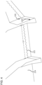
FIG. 2 is a side cross-section view of a tread element of the tire tread ofFIG. 1 ; -
FIG. 3 is a perspective view of a portion of a tire tread having a variable intensity three-dimensional sipe formed therein; -
FIG. 4 is a close-up perspective view of a portion of the tire tread ofFIG. 3 having a variable intensity three-dimensional sipe formed therein; -
FIG. 5 is a perspective view of a portion of a tire tread mold to form a variable intensity three-dimensional sipe; -
FIG. 6 is a close-up perspective view of a portion of the tire tread ofFIG. 1 to form a variable intensity three-dimensional sipe; -
FIG. 7 is an enlarged view of a three-dimensional sipe blade; and -
FIG. 8 is a process diagram for forming a three-dimensional sipe in a tire tread using a mold. - It will be recognized that some or all of the figures are schematic representations for purposes of illustration. The figures are provided for the purpose of illustrating one or more implementations with the explicit understanding that they will not be used to limit the scope or the meaning of the claims.
- In the description that follows, structures and features that are the same or similar as shown in the various views of the drawings are denoted by the same reference numerals throughout the several views for consistency and simplicity, but it should be appreciated that the various structures or features may differ that those shown.
- For ease of understanding this disclosure the following terms are disclosed:
- "Aspect ratio" of the tire may refer to the ratio of its section height (SH) to its section width (Sw) multiplied by 100% for expression as a percentage.
- "Asymmetric tread" may refer to a tread that has a tread pattern not symmetrical about the centerplane or an equatorial plane (EP) of the tire.
- "Axial" and "axially" may refer to lines or directions that are parallel to an axis of rotation of the tire.
- "Circumferential" may refer to lines or directions extending along the perimeter of the surface of the annular tire tread perpendicular to an axial direction.
- "Groove" may refer to an elongated void area in a tire tread that may extend circumferentially or laterally about the tire tread in a straight, curved, zigzag or any other suitable manner. Circumferentially and laterally extending grooves may sometimes have common portions. The "groove width" may be equal to a tread surface area occupied by a groove or groove portion, thus, the groove width may be its average width over its length. Grooves may be of varying depths in a tire. The depth of a groove may vary around the circumference of the tread, or the depth of one groove may be constant but vary from the depth of another groove in the tire. In some embodiments, the depth of the groove may be constant along the tire. If such narrow or wide grooves are of substantially reduced depth as compared to wide circumferential grooves which they interconnect, they may be regarded as forming "tie bars" tending to maintain a rib-like character in the tread region involved.
- "Net-to-gross ratio" may refer to the total area of ground contacting tread elements between the lateral edges around the entire circumference of the tread divided by the gross area of the entire tread between the lateral edges.
- "Non-directional tread" may refer to a tread that has no preferred direction of forward travel and is not required to be positioned on a vehicle in a specific wheel position or positions to ensure that the tread pattern is aligned with the preferred direction of travel. Conversely, a directional tread pattern may have a preferred direction of travel requiring specific wheel positioning.
- "Radial" and "radially" may refer to directions radially toward or away from the axis of rotation of the tire.
- "Rib" may refer to a circumferentially extending strip of rubber on the tread with at least one circumferential groove and either a second such groove or a lateral edge, the strip being laterally undivided by full-depth grooves.
- "Sipe" may refer to small slots molded or cut into the tread elements of the tire that subdivide the tread surface and may improve traction.
- "Tread element" or "traction element" may refer to a rib, lug or a block element.
- "Lugs" may refer to the section of the tread element that make contact with a surface.
- "Voids" may refer to spaces that are located between the lugs.
- Sipes are sometimes cut or molded into tread to improve traction and resistance to wear. When implementing a three-dimensional sipe, the sipe oscillation in a radial direction of the tire has been constant. This can result in a compromise between an aggressive radial oscillation that makes the tread rubber difficult to extract from a mold or a less aggressive oscillation that results in reduced stability between two adjacent tread blocks of rubber when loaded in the tire footprint in service. By varying the intensity of the radial oscillation of the sipe blade, an improved three-dimensional sipe can result in improved stability provided between the tread blocks with a higher frequency oscillation to the sipe at an outer radial location of the tire tread and improved flexibility to facilitate removal of the tire tread from a mold with a lower frequency oscillation to the sipe at an inner radial location of the tire tread.
- The frequency oscillation can be higher near the mold floor, which can result in a tire tread performing better when the tread is tall and near new when the tread blocks are most flexible away from the floor of the tread and need the most support. The oscillation frequency decreases from the mold floor to the top of the mold. This decreasing frequency of oscillation can reduce the amount of lock-up between adjacent tread blocks as the tread wears away. However, the tread blocks become stiffer as the tread wears away toward the tread floor by virtue of the tread blocks being shorter as the tread wears and, therefore, may be less reliant on the adjacent tread blocks for support. This variable frequency oscillation can allow manufacturing of a tread that may otherwise be unfeasible by uniform intensity siping.
-
FIG. 1 is a front view of a portion of atire tread 100 of a tire, according to some embodiments. The tire may include a pneumatic tire. Thetire tread 100 may include a rotational axis AA and atread pattern 110. Specifically, thetire tread 100 may include a plurality oftread elements 112 positioned on a surface of thetire tread 100 that provide thetread pattern 110. Thetire tread 100 may be molded with the tire, or molded separately and thereafter coupled to an outer surface of the tire (e.g., via an adhesive, curing, fusion bonding, heat bonding, etc.). - The plurality of
tread elements 112 may include a plurality ofcircumferential lugs 113 separated byvoids 114. A connectingblock 115 may be positioned in the void 114 between each of thelugs 113, and coupled to each of theadjacent lugs 113.FIG. 2 is a side cross-section view of a portion of thetire tread 100 includingsingle tread element 112. As seen inFIG. 2 , each tread element has a height "h". A height of each of the connectingblock 115 may be smaller than the height h of thetread elements 112 such that the connectingblocks 115 do not contact the surface on which thetire tread 100 is positioned. Furthermore, thetire tread 100 may have a half width "w" (FIG. 1 ) measured from a circumferential axis Ac of thetire tread 100 to an axial end thereof. - A plurality of
circumferential grooves 116 may be provided between each of the plurality oftread elements 112. Thetread elements 112 may also includeshoulder blocks 118 positioned at axial ends of thetire tread 100. A plurality ofnotches 119 or slots may be provided in the shoulder blocks 118. - It is to be appreciated that while the
tire tread 100 is shown as having aparticular tread pattern 110, thetire tread 100 may have any suitable tread pattern. For example, the plurality oftread elements 112 may be axially or circumferentially positioned on a surface of thetire tread 100, include straight, curved or zig zag grooves, a pitch pattern, a non-directional tread pattern, a symmetric tread or an asymmetric tread. Furthermore, thetire tread 100 may have any suitable aspect ratio or net-to-gross ratio. - The
tire tread 100 may include one ormore sipes 122 can be formed in one or more of thetread elements 112. For instance, the one ormore sipes 122 may be formed in thelug 113, the connectingblock 115, and/or thevoid 114. The one ormore sipes 122 may be molded into thetire tread 100, for example during a molding operation of thetire tread 100, or cut into thetread elements 112 after molding of thetire tread 100. Moreover, the one ormore sipes 122 may be inclined towards a direction of rotation of thetire tread 100, perpendicular to a direction of rotation of thetire tread 100, or at any angle from 0 degrees to 90 degrees relative to the direction of rotation of thetire tread 100. In some implementations, the one ormore sipes 122 may be set at an angle relative to the circumferential axis AC of thetire tread 100. - Each
sipe 122 included in the one ormore sipes 122 may be positioned parallel to anadjacent sipe 122 at any suitable pitch or distance therefrom. In some embodiments, the distance may be in a range of 5 mm to 40 mm inclusive of all ranges and values therebetween. Furthermore, the distance or pitch may be fixed or variable. - Furthermore, each of the one or
more sipes 122 may have a sipe depth d greater than 50% of the height h of each of the plurality oftread elements 112, measured from a top surface of thetread element 112 positioned opposite the surface of thetire tread 100 on which thetread elements 112 are positioned. For example, each of the one ormore sipes 122 may have a sipe depth d in a range of 60% to 100% of the height h of the plurality oftread elements 112 inclusive of all ranges and values therebetween. In some embodiments, each of the one ormore sipes 122 may have a sipe depth greater than 100% of the height of the plurality of tread elements (e.g., about 101% to 110% of the height h of the plurality oftread elements 112 inclusive of all ranges and values therebetween). -
FIGS. 3-4 depict an implementation of atire tread 200 with a plurality of three-dimensional sipes 222 formed in thetire tread 200. Thetire tread 200 can be formed in a similar manner to thetire tread 100 ofFIG. 1 and includes a plurality oftread elements 212 that may include a plurality ofcircumferential lugs 213 separated byvoids 214 with a connectingblock 215 positioned in the void 214 between each of thelugs 213, a plurality ofcircumferential grooves 216 provided between each of the plurality oftread elements 212, andshoulder blocks 218 positioned at axial ends of the tire tread 210 with a plurality ofnotches 219 or slots provided in the shoulder blocks 218. - In the implementation shown, the
tire tread 200 may include one or more three-dimensional sipes 222 can be formed in one or more of thetread elements 212 and/or the plurality ofgrooves 216. For instance, the one or more three-dimensional sipes 222 may be formed in thelug 213, the connectingblock 215, and/or thevoid 214. The one or more three-dimensional sipes 222 may be molded into thetire tread 200, for example during a molding operation of thetire tread 200, or cut into thetread elements 212 after molding of thetire tread 200. Moreover, the one or more three-dimensional sipes 222 may be inclined towards a direction of rotation of thetire tread 200, perpendicular to a direction of rotation of thetire tread 200, or at any angle from 0 degrees to 90 degrees relative to the direction of rotation of thetire tread 200. In some implementations, the one or more three-dimensional sipes 122 may be set at an angle relative to the circumferential axis Ac of thetire tread 200. - Each three-
dimensional sipe 222 included in the one or more three-dimensional sipes 222 may be positioned parallel to an adjacent three-dimensional sipe 222 at any suitable pitch or distance therefrom. In some embodiments, the distance may be in a range of 5 mm to 40 mm inclusive of all ranges and values therebetween. Furthermore, the distance or pitch may be fixed or variable. - Furthermore, each of the one or more three-
dimensional sipes 222 may have a three-dimensional sipe depth d greater than 50% of the height h of each of the plurality oftread elements 212, measured from a top surface of thetread element 212 positioned opposite the surface of thetire tread 200 on which thetread elements 212 are positioned. For example, each of the one or more three-dimensional sipes 222 may have a three-dimensional sipe depth d in a range of 60% to 100% of the height h of the plurality oftread elements 212 inclusive of all ranges and values therebetween. In some embodiments, each of the one or more three-dimensional sipes 222 may have a three-dimensional sipe depth greater than 100% of the height of the plurality of tread elements (e.g., about 101% to 110% of the height h of the plurality oftread elements 212 inclusive of all ranges and values therebetween). - In the implementation shown, the one or more three-
dimensional sipes 222 can extend along the rotational axis AA into anadjacent groove 216 of the plurality ofgrooves 216. In some implementations, aterminal end 224 can be provided at one or more ends of each three-dimensional sipe 222. Theterminal end 224 may include an opening to permit removal of a sipe blade of a mold, as will be described in greater detail in reference toFIGS. 5-7 . The three-dimensional sipes 222 shown include a zig-zag pattern along a length Ls of the three-dimensional sipe 222, as will be discussed in greater detail in reference toFIGS. 5-7 , thesipe 222 includes alternating saw-toothed type patterns to provide a three-dimensional shape to thesipe 222 in both the axial length Ls of thesipe 222 and perpendicular to or at any other angle relative to the axial length Ls of thesipe 222. In other implementations, a sinusoidal pattern, a square pattern, a triangular pattern, or any other pattern may be implemented for the three-dimensional sipe 222. - The pattern of the three-
dimensional sipe 222 oscillates with a decreasing frequency from atop end 226 of the three-dimensional sipe 222 to abottom end 228 of the three-dimensional sipe 222 along the height of the three-dimensional sipe 222. That is, a high frequency of oscillation of the three-dimensional pattern is present at thetop end 226 and a lower frequency of oscillation of the three-dimensional pattern is present at thebottom end 228. The high oscillation may perform better when thetire tread 200 and thetread element 212 into which the three-dimensional sipe 222 is formed into is tall and near new, while still permitting the three-dimensional sipe mold to be removed from within the molded three-dimensional sipe 222 after curing as thetread element 212 may be more flexible. The high oscillation provides additional support to thetread element 212 even though thetread element 212 is more flexible. The frequency of oscillation decreases as the height of the three-dimensional sipe 222 decreases to thebottom end 228. This decreases the amount of lock-up between adjacent tread element portions as the tread wears away. However, each tread element portion becomes stiffer by virtue of the decreasing height as thetire tread 200, and therefore is less reliant on the adjacent tread element portions for support. - An amplitude of the three-
dimensional sipe 222 varies along the height of the three-dimensional sipe 222 and may vary along the axial length Ls of the three-dimensional sipe 222. That is, the three-dimensional pattern has a first amplitude at thetop end 226 of the three-dimensional sipe 222 and a second amplitude at thebottom end 228 of the three-dimensional sipe 222, the first amplitude greater than the second amplitude. In some implementations, the amplitude of the three-dimensional sipe 222 may vary at different positions of the three-dimensional sipe 222, such as higher amplitudes of the oscillation at theterminal end 224. -
FIGS. 5-7 depict an implementation of atire tread mold 300 having one or more three-dimensional siping blades 310. Themold 300 includes a plurality of lug recesses 313 separated byvoid forming protrusions 314. A connectingblock recess 315 may be formed in thevoid forming protrusion 314 between each of the lug recesses 313 The depth of eachlug recess 313 defines the height "h" of thelugs blocks tire tread tire tread - A plurality of
groove protrusions 316 may be provided between each of the plurality oftread forming elements mold 300 can further include tread forming elements for formingshoulder blocks mold 300 and/or for forming a plurality ofnotches - It is to be appreciated that while the
mold 300 is shown as having a particular tread pattern, themold 300 may have any other suitable tread pattern. For example, the plurality oftread forming elements mold 300 may have any suitable combination oftread forming elements - The
mold 300 may include one or more three-dimensional sipe blades 310. For instance, the one or more three-dimensional sipe blades 310 may be positioned to form a corresponding sipe in a lug, connecting block, and/or void. The one or more three-dimensional sipe blades 310 may be inclined towards a direction of rotation of the resulting tire tread, perpendicular to a direction of rotation of the resulting tire tread, or at any angle from 0 degrees to 90 degrees relative to the direction of rotation of the resulting tire tread. In some implementations, the one or more three-dimensional sipe blades 310 may be set at an angle relative to the circumferential axis Ac of the resulting tire tread. - Each three-
dimensional sipe blade 310 may be positioned parallel to an adjacent three-dimensional sipe blade 310 at any suitable pitch or distance therefrom. In some embodiments, the distance may be in a range of 5 mm to 40 mm inclusive of all ranges and values therebetween. Furthermore, the distance or pitch may be fixed or variable. - Furthermore, each of the one or more three-
dimensional sipe blades 310 may have a sipe blade height corresponding to the sipe depth d, which can be greater than 50% of the height h of a resulting tread element. For example, each of the one or more three-dimensional sipe blades 310 may have a sipe height corresponding to a sipe depth d in a range of 60% to 100% of the height h of the resulting tread element inclusive of all ranges and values therebetween. In some embodiments, each of the one or more three-dimensional sipe blades 310 may have a sipe height greater than 100% of the height of the resulting tread element (e.g., about 101% to 110% of the height h of the plurality of resulting tread element inclusive of all ranges and values therebetween). - In some implementations, a
terminal end 324 can be provided at one or more ends of each three-dimensional sipe blade 310. Theterminal end 324 may include a protrusion element (e.g., a cylinder, square, or other three-dimensional geometric element) to facilitate removal of the three-dimensional sipe blade 310 when extracting a cured tire tread from themold 300. The three-dimensional sipe blades 310 shown include a zig-zag pattern along a blade length LB of the three-dimensional sipe blade 310 and include an alternating saw-toothed type pattern to provide a three-dimensional shape to the resulting sipe in both the blade length LB of the resulting sipe and perpendicular to or at any other angle relative to the blade length LB of the resulting sipe. In other implementations, a sinusoidal pattern, a square pattern, a triangular pattern, or any other pattern may be implemented for the three-dimensional sipe blade 310. - As shown best in
FIG. 7 , the three-dimensional sipe blade 310 extends upward from amold base 312 of themold 300. The three-dimensional pattern of the three-dimensional sipe blade 310 oscillates with a decreasing frequency from atop end 326 of the three-dimensional sipe blade 310 to abottom end 328 of the three-dimensional sipe blade 310 along the height of the three-dimensional sipe blade 310. That is, a high frequency of oscillation of the three-dimensional pattern is present at thetop end 326 and a lower frequency of oscillation of the three-dimensional pattern is present at thebottom end 328. The high oscillation may perform better when the resulting tire tread and the tread element into which the three-dimensional sipe is formed into is tall and near new, while still permitting the three-dimensional sipe mold 300 and three-dimensional sipe blade 310 to be removed from within the molded three-dimensional sipe after curing since the height of the molded tread element may result in more flexibility to be resiliently deformed to extract the three-dimensional sipe blade 310. The high oscillation provides additional support to the tread element from adjacent portions of the tread element even though the tread element is more flexible. The frequency of oscillation decreases as the height of the three-dimensional sipe blade 310 decreases to thebottom end 328. This decreases the amount of lock-up between adjacent tread element portions as the tread wears away. However, each tread element portion becomes stiffer by virtue of the decreasing height of the tire tread, and therefore is less reliant on the adjacent tread element portions for support. - An amplitude of the three-
dimensional sipe blade 310 varies along the height of the three-dimensional sipe blade 310 and may vary along the blade length LB of the three-dimensional sipe blade 310. That is, the three-dimensional pattern has a first amplitude at thetop end 326 of the three-dimensional sipe blade 310 and a second amplitude at thebottom end 328 of the three-dimensional sipe blade 310, the first amplitude greater than the second amplitude. In some implementations, the amplitude of the three-dimensional sipe blade 310 may vary at different positions of the three-dimensional sipe blade 310, such as higher amplitudes of the oscillation at theterminal end 324. -
FIG. 8 is a schematic flow diagram of anexample process 800 for forming a tire tread with varying oscillation three-dimensional sipes. Theprocess 800 includes providing a tire tread mold having one or more three-dimensional sipe blades (block 802) with varying oscillation of the three-dimensional pattern of for the three-dimensional sipe blade, such asmold 300 ofFIGS. 5-7 . Theprocess 800 may include forming a tire tread using the mold (block 804). In some implementations, a plurality of molds may be positioned adjacent to each other to form an elongated tire tread. In other implementations, the mold may be a single mold for a predetermined length of tire tread to be formed with the three-dimensional sipes therein. Theprocess 800 may also include extracting the tire tread from the mold (block 806). Extracting the tire tread from the mold may be done manually and/or via a tire tread extraction machine. In some implementations, the tire tread can be coupled to or otherwise attached to a tire casing to form a tire. The tire tread and tire casing may be cured together to form a new tire. - While this specification contains many specific implementation details, these should not be construed as limitations on the scope of what may be claimed, but rather as descriptions of features specific to particular implementations.
- The terms "coupled" and the like as used herein mean the joining of two components directly or indirectly to one another. Such joining may be stationary (e.g., permanent) or moveable (e.g., removable or releasable). Such joining may be achieved with the two components or the two components and any additional intermediate components being integrally formed as a single unitary body with one another or with the two components or the two components and any additional intermediate components being attached to one another.
- It is important to note that the construction and arrangement of the system shown in the various exemplary implementations is illustrative only and not restrictive in character. All changes and modifications that come within the scope of the described implementations are desired to be protected. It should be understood that some features may not be necessary and implementations lacking the various features may be contemplated as within the scope of the application, the scope being defined by the claims that follow. In reading the claims, it is intended that when words such as "a," "an," "at least one," or "at least one portion" are used there is no intention to limit the claim to only one item unless specifically stated to the contrary in the claim.
Claims (9)
- A tire tread (200) provided with a tread pattern, the tread pattern comprising:a plurality of tread elements (212) positioned on a tire tread surface providing the tread pattern, the plurality of tread elements (212) positioned at least one of axially or circumferentially on the tire tread surface, each of the plurality of tread elements (212) have a height (h) between a top contact surface of the tread element (212) and a surface of the tire tread (200) on which the plurality of tread elements (212) are positioned;a plurality of grooves (216) provided between the plurality of tread elements (212); anda sipe (222) formed in at least one of the plurality of tread elements (212), the sipe (222) comprising a three-dimensional pattern that oscillates with a decreasing frequency from a first frequency of oscillation in the depth direction of the sipe (222) at an upper end portion of the sipe (222), the upper end portion comprising a top end (226) of the sipe (222) to a second frequency of oscillation in the depth direction of the sipe (222) at a lower end portion of the sipe (222) comprising a bottom end (228) of the sipe (222), the first frequency of oscillation being greater than the second frequency of oscillation, the three-dimensional pattern comprising a zig-zag pattern extending along the top contact surface of the tread element (212),characterized in thatthe three-dimensional pattern has a first amplitude in the depth direction of the sipe (222) at an upper end portion of the sipe (222) and a second amplitude in the depth direction of the sipe (222) at a lower end portion of the sipe (222), wherein the first amplitude is greater than the second amplitude.
- The tire tread (200) of claim 1, wherein the three-dimensional pattern comprises one of a saw-tooth, sinusoidal, square, or triangular pattern.
- The tire tread (200) of claim 1, wherein the sipe (222) has a sipe depth in a range of 60% to 100% of a height (h) of the plurality of tread elements (212).
- The tire tread (200) of claim 1, wherein the sipe (222) has a sipe depth greater than 100% of a height (h) of the plurality of tread elements (212).
- A tire having a rotational axis, provided with the tire tread (200) of claim 1.
- The tire of claim 5, wherein the tire is a pneumatic tire.
- A method of forming a tire tread (200) with a varying frequency of oscillation for a three-dimensional sipe (222), the method comprising:providing a tire tread (200) mold, the tire tread (200) mold having one or more three-dimensional sipe blades (310), each of the one or more three-dimensional sipe blades (310) having:a depth direction measured from a top end of the one or more three-dimensional sipe blades (310) to a bottom end of the one or more three-dimensional sipe blades (310);a three-dimensional pattern that oscillates with a decreasing frequency from a first frequency of oscillation in the depth direction of the blade (310) at an upper end portion of the one or more three-dimensional blades (310) comprising the top end (326) to a second frequency of oscillation in the depth direction of the blade (310) at a lower end portion of the one or more three-dimensional blades (310) comprising the bottom end (328) along the height of the one or more three-dimensional sipe blades (310), the first frequency of oscillation being greater than the second frequency of oscillation, the three-dimensional pattern having a zig-zag pattern extending along the length of the one or more sipe blades (310);forming a tire tread (200) using the mold, the tire tread (200) including a sipe (222) formed in at least one tread element (212), the sipe (222) comprising the three-dimensional pattern; andextracting the tire tread (200) from the mold,characterized in thatthe three-dimensional pattern has a first amplitude in the depth direction of the blade (310) at an upper end portion of the blade (310) and a second amplitude in the depth direction of the blade (310) at a lower end portion of the blade (310), wherein the first amplitude is greater than the second amplitude.
- The method of claim 7, wherein the three-dimensional pattern comprises one of a saw-tooth, sinusoidal, square, or triangular pattern.
- The method of claim 7, wherein the sipe (222) has a sipe depth in a range of 60% to 100% of a height (h) of the at least one tread element (212).
Applications Claiming Priority (2)
| Application Number | Priority Date | Filing Date | Title |
|---|---|---|---|
| US201762477109P | 2017-03-27 | 2017-03-27 | |
| PCT/US2018/023500 WO2018183053A1 (en) | 2017-03-27 | 2018-03-21 | Variable oscillation three dimensional sipe |
Publications (3)
| Publication Number | Publication Date |
|---|---|
| EP3600919A1 EP3600919A1 (en) | 2020-02-05 |
| EP3600919A4 EP3600919A4 (en) | 2020-10-28 |
| EP3600919B1 true EP3600919B1 (en) | 2024-03-20 |
Family
ID=63676669
Family Applications (1)
| Application Number | Title | Priority Date | Filing Date |
|---|---|---|---|
| EP18776170.5A Active EP3600919B1 (en) | 2017-03-27 | 2018-03-21 | Variable oscillation three dimensional sipe |
Country Status (6)
| Country | Link |
|---|---|
| US (1) | US12168372B2 (en) |
| EP (1) | EP3600919B1 (en) |
| JP (2) | JP2020515468A (en) |
| CN (1) | CN110461625A (en) |
| BR (1) | BR112019020044A2 (en) |
| WO (1) | WO2018183053A1 (en) |
Families Citing this family (8)
| Publication number | Priority date | Publication date | Assignee | Title |
|---|---|---|---|---|
| BR112019020044A2 (en) * | 2017-03-27 | 2020-04-28 | Bridgestone Bandag Llc | tire, tread pattern for a tire tread, and method for forming a tire tread |
| JP2020093675A (en) * | 2018-12-13 | 2020-06-18 | 株式会社ブリヂストン | Automobile pneumatic radial tire |
| CN113453915B (en) * | 2019-02-22 | 2024-12-20 | 横滨橡胶株式会社 | Pneumatic tires |
| JP1663066S (en) * | 2019-11-29 | 2020-07-06 | ||
| USD935989S1 (en) * | 2020-04-01 | 2021-11-16 | Bridgestone Bandag, Llc | Tire |
| CN113147267B (en) * | 2021-03-30 | 2025-04-15 | 中策橡胶集团股份有限公司 | A tire for quickly diagnosing vehicle condition |
| USD1008159S1 (en) * | 2022-03-25 | 2023-12-19 | Bridgestone Bandag, Llc | Tire |
| DE102023208482A1 (en) | 2023-09-04 | 2025-03-06 | Continental Reifen Deutschland Gmbh | vehicle tires |
Family Cites Families (38)
| Publication number | Priority date | Publication date | Assignee | Title |
|---|---|---|---|---|
| US2983005A (en) | 1959-02-17 | 1961-05-09 | Morris Bean & Company | Sipe blades |
| DE3872001T2 (en) * | 1987-03-10 | 1992-12-03 | Sumitomo Rubber Ind | RADIAL TIRE. |
| FR2612129B1 (en) * | 1987-03-10 | 1989-09-29 | Michelin & Cie | TREAD FOR RADIAL TIRES OF WHICH THE RELATED ELEMENTS ARE INCORPORATED WITH BROKEN OR CORRUGATED LINE TRACKS IN THE SENSE OF THEIR DEPTHS |
| JPH0435005U (en) | 1990-07-17 | 1992-03-24 | ||
| JPH04197809A (en) | 1990-11-29 | 1992-07-17 | Bridgestone Corp | Block of pneumatic radial tire |
| JP3110783B2 (en) * | 1991-04-02 | 2000-11-20 | 株式会社ブリヂストン | Pneumatic radial tire |
| JPH06143941A (en) | 1992-11-05 | 1994-05-24 | Yokohama Rubber Co Ltd:The | Pneumatic tire |
| FR2722144B1 (en) | 1994-07-05 | 1996-09-27 | Michelin & Cie | TIRE TREAD |
| EP0820885A3 (en) * | 1996-07-24 | 1998-07-08 | Bridgestone Corporation | Pneumatic tire |
| IT1290210B1 (en) | 1997-01-29 | 1998-10-22 | Pirelli | METHOD FOR THE PRODUCTION OF TIRES, FOR THE REALIZATION OF VULCANIZATION MOLDS FOR SAID TIRES, TIRES AND MOLDS SO |
| JPH11208223A (en) * | 1998-01-28 | 1999-08-03 | Bridgestone Corp | Pneumatic tire |
| JP2000177329A (en) | 1998-12-14 | 2000-06-27 | Ohtsu Tire & Rubber Co Ltd :The | Tire tread |
| JP3648179B2 (en) * | 2001-07-18 | 2005-05-18 | 住友ゴム工業株式会社 | Pneumatic tire and its vulcanization mold |
| JP3682918B2 (en) * | 2001-10-17 | 2005-08-17 | 東洋ゴム工業株式会社 | Pneumatic tire |
| JP4316452B2 (en) * | 2003-09-29 | 2009-08-19 | 横浜ゴム株式会社 | Pneumatic tire |
| US7143799B2 (en) | 2003-11-20 | 2006-12-05 | The Goodyear Tire & Rubber Company | Three-dimensional sipes for treads |
| JP4330455B2 (en) * | 2004-01-09 | 2009-09-16 | 住友ゴム工業株式会社 | Pneumatic tire |
| US7467652B2 (en) * | 2004-08-06 | 2008-12-23 | The Goodyear Tire & Rubber Company | Three-dimensional tread sipes and mold blade for forming three-dimensional tread sipes |
| JP4285609B2 (en) | 2004-09-06 | 2009-06-24 | 横浜ゴム株式会社 | Pneumatic tire |
| JP4516415B2 (en) | 2004-12-08 | 2010-08-04 | 住友ゴム工業株式会社 | Pneumatic tire |
| US7360568B2 (en) | 2005-01-27 | 2008-04-22 | Bridgestone Firestone North American Tire, Llc | Tire having narrowing sipes |
| JP4715343B2 (en) * | 2005-07-06 | 2011-07-06 | 横浜ゴム株式会社 | Pneumatic tire |
| DE102005058365A1 (en) * | 2005-12-06 | 2007-06-14 | Continental Aktiengesellschaft | Tread pattern |
| SK882006A3 (en) | 2006-06-13 | 2008-01-07 | Matador Rubber, S. R. O. | Tyre protector and segment suitable for mounting into vulcanisation form for creating segment slot in block of tyre protector |
| JP4999709B2 (en) | 2007-04-16 | 2012-08-15 | 東洋ゴム工業株式会社 | Sipe blade and tire molded using the same |
| JP2010023586A (en) | 2008-07-16 | 2010-02-04 | Bridgestone Corp | Pneumatic tire |
| KR101040630B1 (en) | 2008-11-17 | 2011-06-13 | 한국타이어 주식회사 | Blade for cuff forming of automotive vulcanization mold |
| FR2939362B1 (en) * | 2008-12-05 | 2010-11-19 | Michelin Soc Tech | ROLLER BAND COMPRISING PLOTS |
| FR2961741B1 (en) | 2010-06-25 | 2012-08-03 | Michelin Soc Tech | LAMELLE FOR A TRIM OF A MOLD FOR THE VULCANIZATION OF A TIRE TREAD OF A TIRE |
| DE102012101149A1 (en) | 2011-11-02 | 2013-05-02 | Continental Reifen Deutschland Gmbh | Vehicle tires |
| JP5429267B2 (en) | 2011-11-28 | 2014-02-26 | 横浜ゴム株式会社 | Pneumatic tire |
| US9616716B2 (en) * | 2011-12-14 | 2017-04-11 | Bridgestone Americas Tire Operations, Llc | Three dimensional sipe |
| EP2913205B1 (en) * | 2012-10-24 | 2018-06-06 | Bridgestone Corporation | Pneumatic tire |
| SK500522013A3 (en) | 2013-12-10 | 2015-07-01 | Continental Matador Rubber, S.R.O. | Tire tread and plate for mounting in vulcanizing mold for forming sipe in tire tread block |
| CA2940407C (en) | 2014-03-07 | 2019-06-11 | Bridgestone Americas Tire Operations, Llc | Tire tread featuring a sipe |
| JP6699193B2 (en) * | 2016-01-21 | 2020-05-27 | 住友ゴム工業株式会社 | Pneumatic tire |
| JP6747888B2 (en) * | 2016-06-30 | 2020-08-26 | Toyo Tire株式会社 | Pneumatic tire |
| BR112019020044A2 (en) * | 2017-03-27 | 2020-04-28 | Bridgestone Bandag Llc | tire, tread pattern for a tire tread, and method for forming a tire tread |
-
2018
- 2018-03-21 BR BR112019020044A patent/BR112019020044A2/en not_active IP Right Cessation
- 2018-03-21 US US16/493,320 patent/US12168372B2/en active Active
- 2018-03-21 EP EP18776170.5A patent/EP3600919B1/en active Active
- 2018-03-21 JP JP2020501419A patent/JP2020515468A/en active Pending
- 2018-03-21 WO PCT/US2018/023500 patent/WO2018183053A1/en not_active Ceased
- 2018-03-21 CN CN201880021047.2A patent/CN110461625A/en active Pending
-
2021
- 2021-07-20 JP JP2021119213A patent/JP7327749B2/en active Active
Also Published As
| Publication number | Publication date |
|---|---|
| JP2021169309A (en) | 2021-10-28 |
| EP3600919A1 (en) | 2020-02-05 |
| BR112019020044A2 (en) | 2020-04-28 |
| JP2020515468A (en) | 2020-05-28 |
| EP3600919A4 (en) | 2020-10-28 |
| JP7327749B2 (en) | 2023-08-16 |
| US12168372B2 (en) | 2024-12-17 |
| CN110461625A (en) | 2019-11-15 |
| WO2018183053A1 (en) | 2018-10-04 |
| US20200070588A1 (en) | 2020-03-05 |
Similar Documents
| Publication | Publication Date | Title |
|---|---|---|
| EP3600919B1 (en) | Variable oscillation three dimensional sipe | |
| EP3496958B1 (en) | Apparatuses and methods for improving chunking and cracking resistance of tires | |
| US8973630B2 (en) | Tire including concave recesses in a circumferential tread | |
| EP1616719B1 (en) | Pneumatic tire | |
| CN104417276B (en) | Air tread and tooling blade with pattern sipe | |
| EP1073562B1 (en) | Tire tread with 3-dimensional sipe | |
| JP4460075B2 (en) | Tread pattern and mold for tire tread | |
| EP1859962B1 (en) | Pneumatic tire with tread siping | |
| EP2342069B1 (en) | Molded tire tread with an undulated sipe | |
| EP3444129A1 (en) | Pneumatic tire | |
| EP1676727B1 (en) | Tire tread having a tread block with an undercut design | |
| CN109562652B (en) | Heavy Truck Tire Treads and Heavy Truck Tires | |
| US20240066928A1 (en) | Systems and methods for sipe patterns | |
| US20070295435A1 (en) | Tire and tire tread with sipes of defined curvature | |
| JP2000318413A (en) | Pneumatic tire and its vulcanizing mold | |
| EP1872975A1 (en) | Tire with a tread having sipes and a sipe blade for tires | |
| EP1872976B1 (en) | Tire with sipes of defined curvature |
Legal Events
| Date | Code | Title | Description |
|---|---|---|---|
| STAA | Information on the status of an ep patent application or granted ep patent |
Free format text: STATUS: THE INTERNATIONAL PUBLICATION HAS BEEN MADE |
|
| PUAI | Public reference made under article 153(3) epc to a published international application that has entered the european phase |
Free format text: ORIGINAL CODE: 0009012 |
|
| STAA | Information on the status of an ep patent application or granted ep patent |
Free format text: STATUS: REQUEST FOR EXAMINATION WAS MADE |
|
| 17P | Request for examination filed |
Effective date: 20191024 |
|
| AK | Designated contracting states |
Kind code of ref document: A1 Designated state(s): AL AT BE BG CH CY CZ DE DK EE ES FI FR GB GR HR HU IE IS IT LI LT LU LV MC MK MT NL NO PL PT RO RS SE SI SK SM TR |
|
| AX | Request for extension of the european patent |
Extension state: BA ME |
|
| DAV | Request for validation of the european patent (deleted) | ||
| DAX | Request for extension of the european patent (deleted) | ||
| A4 | Supplementary search report drawn up and despatched |
Effective date: 20200925 |
|
| RIC1 | Information provided on ipc code assigned before grant |
Ipc: B60C 11/12 20060101AFI20200921BHEP |
|
| STAA | Information on the status of an ep patent application or granted ep patent |
Free format text: STATUS: EXAMINATION IS IN PROGRESS |
|
| 17Q | First examination report despatched |
Effective date: 20210811 |
|
| RIC1 | Information provided on ipc code assigned before grant |
Ipc: B60C 11/04 20060101ALI20230731BHEP Ipc: B60C 11/03 20060101ALI20230731BHEP Ipc: B60C 11/12 20060101AFI20230731BHEP |
|
| GRAP | Despatch of communication of intention to grant a patent |
Free format text: ORIGINAL CODE: EPIDOSNIGR1 |
|
| STAA | Information on the status of an ep patent application or granted ep patent |
Free format text: STATUS: GRANT OF PATENT IS INTENDED |
|
| INTG | Intention to grant announced |
Effective date: 20231004 |
|
| GRAS | Grant fee paid |
Free format text: ORIGINAL CODE: EPIDOSNIGR3 |
|
| GRAA | (expected) grant |
Free format text: ORIGINAL CODE: 0009210 |
|
| STAA | Information on the status of an ep patent application or granted ep patent |
Free format text: STATUS: THE PATENT HAS BEEN GRANTED |
|
| P01 | Opt-out of the competence of the unified patent court (upc) registered |
Effective date: 20240112 |
|
| AK | Designated contracting states |
Kind code of ref document: B1 Designated state(s): AL AT BE BG CH CY CZ DE DK EE ES FI FR GB GR HR HU IE IS IT LI LT LU LV MC MK MT NL NO PL PT RO RS SE SI SK SM TR |
|
| REG | Reference to a national code |
Ref country code: GB Ref legal event code: FG4D |
|
| REG | Reference to a national code |
Ref country code: CH Ref legal event code: EP |
|
| REG | Reference to a national code |
Ref country code: IE Ref legal event code: FG4D |
|
| REG | Reference to a national code |
Ref country code: DE Ref legal event code: R096 Ref document number: 602018066882 Country of ref document: DE |
|
| REG | Reference to a national code |
Ref country code: NL Ref legal event code: FP |
|
| PG25 | Lapsed in a contracting state [announced via postgrant information from national office to epo] |
Ref country code: LT Free format text: LAPSE BECAUSE OF FAILURE TO SUBMIT A TRANSLATION OF THE DESCRIPTION OR TO PAY THE FEE WITHIN THE PRESCRIBED TIME-LIMIT Effective date: 20240320 |
|
| REG | Reference to a national code |
Ref country code: LT Ref legal event code: MG9D |
|
| PG25 | Lapsed in a contracting state [announced via postgrant information from national office to epo] |
Ref country code: GR Free format text: LAPSE BECAUSE OF FAILURE TO SUBMIT A TRANSLATION OF THE DESCRIPTION OR TO PAY THE FEE WITHIN THE PRESCRIBED TIME-LIMIT Effective date: 20240621 |
|
| PG25 | Lapsed in a contracting state [announced via postgrant information from national office to epo] |
Ref country code: HR Free format text: LAPSE BECAUSE OF FAILURE TO SUBMIT A TRANSLATION OF THE DESCRIPTION OR TO PAY THE FEE WITHIN THE PRESCRIBED TIME-LIMIT Effective date: 20240320 Ref country code: RS Free format text: LAPSE BECAUSE OF FAILURE TO SUBMIT A TRANSLATION OF THE DESCRIPTION OR TO PAY THE FEE WITHIN THE PRESCRIBED TIME-LIMIT Effective date: 20240620 |
|
| PG25 | Lapsed in a contracting state [announced via postgrant information from national office to epo] |
Ref country code: RS Free format text: LAPSE BECAUSE OF FAILURE TO SUBMIT A TRANSLATION OF THE DESCRIPTION OR TO PAY THE FEE WITHIN THE PRESCRIBED TIME-LIMIT Effective date: 20240620 Ref country code: NO Free format text: LAPSE BECAUSE OF FAILURE TO SUBMIT A TRANSLATION OF THE DESCRIPTION OR TO PAY THE FEE WITHIN THE PRESCRIBED TIME-LIMIT Effective date: 20240620 Ref country code: LT Free format text: LAPSE BECAUSE OF FAILURE TO SUBMIT A TRANSLATION OF THE DESCRIPTION OR TO PAY THE FEE WITHIN THE PRESCRIBED TIME-LIMIT Effective date: 20240320 Ref country code: HR Free format text: LAPSE BECAUSE OF FAILURE TO SUBMIT A TRANSLATION OF THE DESCRIPTION OR TO PAY THE FEE WITHIN THE PRESCRIBED TIME-LIMIT Effective date: 20240320 Ref country code: GR Free format text: LAPSE BECAUSE OF FAILURE TO SUBMIT A TRANSLATION OF THE DESCRIPTION OR TO PAY THE FEE WITHIN THE PRESCRIBED TIME-LIMIT Effective date: 20240621 Ref country code: FI Free format text: LAPSE BECAUSE OF FAILURE TO SUBMIT A TRANSLATION OF THE DESCRIPTION OR TO PAY THE FEE WITHIN THE PRESCRIBED TIME-LIMIT Effective date: 20240320 Ref country code: BG Free format text: LAPSE BECAUSE OF FAILURE TO SUBMIT A TRANSLATION OF THE DESCRIPTION OR TO PAY THE FEE WITHIN THE PRESCRIBED TIME-LIMIT Effective date: 20240320 |
|
| REG | Reference to a national code |
Ref country code: AT Ref legal event code: MK05 Ref document number: 1667524 Country of ref document: AT Kind code of ref document: T Effective date: 20240320 |
|
| PG25 | Lapsed in a contracting state [announced via postgrant information from national office to epo] |
Ref country code: SE Free format text: LAPSE BECAUSE OF FAILURE TO SUBMIT A TRANSLATION OF THE DESCRIPTION OR TO PAY THE FEE WITHIN THE PRESCRIBED TIME-LIMIT Effective date: 20240320 Ref country code: LV Free format text: LAPSE BECAUSE OF FAILURE TO SUBMIT A TRANSLATION OF THE DESCRIPTION OR TO PAY THE FEE WITHIN THE PRESCRIBED TIME-LIMIT Effective date: 20240320 |
|
| PG25 | Lapsed in a contracting state [announced via postgrant information from national office to epo] |
Ref country code: IS Free format text: LAPSE BECAUSE OF FAILURE TO SUBMIT A TRANSLATION OF THE DESCRIPTION OR TO PAY THE FEE WITHIN THE PRESCRIBED TIME-LIMIT Effective date: 20240720 |
|
| PG25 | Lapsed in a contracting state [announced via postgrant information from national office to epo] |
Ref country code: PT Free format text: LAPSE BECAUSE OF FAILURE TO SUBMIT A TRANSLATION OF THE DESCRIPTION OR TO PAY THE FEE WITHIN THE PRESCRIBED TIME-LIMIT Effective date: 20240722 Ref country code: SM Free format text: LAPSE BECAUSE OF FAILURE TO SUBMIT A TRANSLATION OF THE DESCRIPTION OR TO PAY THE FEE WITHIN THE PRESCRIBED TIME-LIMIT Effective date: 20240320 |
|
| PG25 | Lapsed in a contracting state [announced via postgrant information from national office to epo] |
Ref country code: ES Free format text: LAPSE BECAUSE OF FAILURE TO SUBMIT A TRANSLATION OF THE DESCRIPTION OR TO PAY THE FEE WITHIN THE PRESCRIBED TIME-LIMIT Effective date: 20240320 |
|
| PG25 | Lapsed in a contracting state [announced via postgrant information from national office to epo] |
Ref country code: EE Free format text: LAPSE BECAUSE OF FAILURE TO SUBMIT A TRANSLATION OF THE DESCRIPTION OR TO PAY THE FEE WITHIN THE PRESCRIBED TIME-LIMIT Effective date: 20240320 Ref country code: CZ Free format text: LAPSE BECAUSE OF FAILURE TO SUBMIT A TRANSLATION OF THE DESCRIPTION OR TO PAY THE FEE WITHIN THE PRESCRIBED TIME-LIMIT Effective date: 20240320 |
|
| PG25 | Lapsed in a contracting state [announced via postgrant information from national office to epo] |
Ref country code: AT Free format text: LAPSE BECAUSE OF FAILURE TO SUBMIT A TRANSLATION OF THE DESCRIPTION OR TO PAY THE FEE WITHIN THE PRESCRIBED TIME-LIMIT Effective date: 20240320 |
|
| PG25 | Lapsed in a contracting state [announced via postgrant information from national office to epo] |
Ref country code: PL Free format text: LAPSE BECAUSE OF FAILURE TO SUBMIT A TRANSLATION OF THE DESCRIPTION OR TO PAY THE FEE WITHIN THE PRESCRIBED TIME-LIMIT Effective date: 20240320 |
|
| PG25 | Lapsed in a contracting state [announced via postgrant information from national office to epo] |
Ref country code: SK Free format text: LAPSE BECAUSE OF FAILURE TO SUBMIT A TRANSLATION OF THE DESCRIPTION OR TO PAY THE FEE WITHIN THE PRESCRIBED TIME-LIMIT Effective date: 20240320 |
|
| PG25 | Lapsed in a contracting state [announced via postgrant information from national office to epo] |
Ref country code: SM Free format text: LAPSE BECAUSE OF FAILURE TO SUBMIT A TRANSLATION OF THE DESCRIPTION OR TO PAY THE FEE WITHIN THE PRESCRIBED TIME-LIMIT Effective date: 20240320 Ref country code: SK Free format text: LAPSE BECAUSE OF FAILURE TO SUBMIT A TRANSLATION OF THE DESCRIPTION OR TO PAY THE FEE WITHIN THE PRESCRIBED TIME-LIMIT Effective date: 20240320 Ref country code: RO Free format text: LAPSE BECAUSE OF FAILURE TO SUBMIT A TRANSLATION OF THE DESCRIPTION OR TO PAY THE FEE WITHIN THE PRESCRIBED TIME-LIMIT Effective date: 20240320 Ref country code: PT Free format text: LAPSE BECAUSE OF FAILURE TO SUBMIT A TRANSLATION OF THE DESCRIPTION OR TO PAY THE FEE WITHIN THE PRESCRIBED TIME-LIMIT Effective date: 20240722 Ref country code: PL Free format text: LAPSE BECAUSE OF FAILURE TO SUBMIT A TRANSLATION OF THE DESCRIPTION OR TO PAY THE FEE WITHIN THE PRESCRIBED TIME-LIMIT Effective date: 20240320 Ref country code: IS Free format text: LAPSE BECAUSE OF FAILURE TO SUBMIT A TRANSLATION OF THE DESCRIPTION OR TO PAY THE FEE WITHIN THE PRESCRIBED TIME-LIMIT Effective date: 20240720 Ref country code: ES Free format text: LAPSE BECAUSE OF FAILURE TO SUBMIT A TRANSLATION OF THE DESCRIPTION OR TO PAY THE FEE WITHIN THE PRESCRIBED TIME-LIMIT Effective date: 20240320 Ref country code: EE Free format text: LAPSE BECAUSE OF FAILURE TO SUBMIT A TRANSLATION OF THE DESCRIPTION OR TO PAY THE FEE WITHIN THE PRESCRIBED TIME-LIMIT Effective date: 20240320 Ref country code: CZ Free format text: LAPSE BECAUSE OF FAILURE TO SUBMIT A TRANSLATION OF THE DESCRIPTION OR TO PAY THE FEE WITHIN THE PRESCRIBED TIME-LIMIT Effective date: 20240320 Ref country code: AT Free format text: LAPSE BECAUSE OF FAILURE TO SUBMIT A TRANSLATION OF THE DESCRIPTION OR TO PAY THE FEE WITHIN THE PRESCRIBED TIME-LIMIT Effective date: 20240320 |
|
| REG | Reference to a national code |
Ref country code: CH Ref legal event code: PL |
|
| PG25 | Lapsed in a contracting state [announced via postgrant information from national office to epo] |
Ref country code: LU Free format text: LAPSE BECAUSE OF NON-PAYMENT OF DUE FEES Effective date: 20240321 |
|
| PG25 | Lapsed in a contracting state [announced via postgrant information from national office to epo] |
Ref country code: LU Free format text: LAPSE BECAUSE OF NON-PAYMENT OF DUE FEES Effective date: 20240321 |
|
| PG25 | Lapsed in a contracting state [announced via postgrant information from national office to epo] |
Ref country code: IT Free format text: LAPSE BECAUSE OF FAILURE TO SUBMIT A TRANSLATION OF THE DESCRIPTION OR TO PAY THE FEE WITHIN THE PRESCRIBED TIME-LIMIT Effective date: 20240320 |
|
| REG | Reference to a national code |
Ref country code: DE Ref legal event code: R097 Ref document number: 602018066882 Country of ref document: DE |
|
| PG25 | Lapsed in a contracting state [announced via postgrant information from national office to epo] |
Ref country code: IT Free format text: LAPSE BECAUSE OF FAILURE TO SUBMIT A TRANSLATION OF THE DESCRIPTION OR TO PAY THE FEE WITHIN THE PRESCRIBED TIME-LIMIT Effective date: 20240320 |
|
| PG25 | Lapsed in a contracting state [announced via postgrant information from national office to epo] |
Ref country code: MC Free format text: LAPSE BECAUSE OF FAILURE TO SUBMIT A TRANSLATION OF THE DESCRIPTION OR TO PAY THE FEE WITHIN THE PRESCRIBED TIME-LIMIT Effective date: 20240320 |
|
| PG25 | Lapsed in a contracting state [announced via postgrant information from national office to epo] |
Ref country code: DK Free format text: LAPSE BECAUSE OF FAILURE TO SUBMIT A TRANSLATION OF THE DESCRIPTION OR TO PAY THE FEE WITHIN THE PRESCRIBED TIME-LIMIT Effective date: 20240320 |
|
| PG25 | Lapsed in a contracting state [announced via postgrant information from national office to epo] |
Ref country code: IE Free format text: LAPSE BECAUSE OF NON-PAYMENT OF DUE FEES Effective date: 20240321 |
|
| PLBE | No opposition filed within time limit |
Free format text: ORIGINAL CODE: 0009261 |
|
| STAA | Information on the status of an ep patent application or granted ep patent |
Free format text: STATUS: NO OPPOSITION FILED WITHIN TIME LIMIT |
|
| PG25 | Lapsed in a contracting state [announced via postgrant information from national office to epo] |
Ref country code: MC Free format text: LAPSE BECAUSE OF FAILURE TO SUBMIT A TRANSLATION OF THE DESCRIPTION OR TO PAY THE FEE WITHIN THE PRESCRIBED TIME-LIMIT Effective date: 20240320 Ref country code: IE Free format text: LAPSE BECAUSE OF NON-PAYMENT OF DUE FEES Effective date: 20240321 Ref country code: DK Free format text: LAPSE BECAUSE OF FAILURE TO SUBMIT A TRANSLATION OF THE DESCRIPTION OR TO PAY THE FEE WITHIN THE PRESCRIBED TIME-LIMIT Effective date: 20240320 Ref country code: CH Free format text: LAPSE BECAUSE OF NON-PAYMENT OF DUE FEES Effective date: 20240331 |
|
| 26N | No opposition filed |
Effective date: 20241223 |
|
| GBPC | Gb: european patent ceased through non-payment of renewal fee |
Effective date: 20240620 |
|
| PG25 | Lapsed in a contracting state [announced via postgrant information from national office to epo] |
Ref country code: SI Free format text: LAPSE BECAUSE OF FAILURE TO SUBMIT A TRANSLATION OF THE DESCRIPTION OR TO PAY THE FEE WITHIN THE PRESCRIBED TIME-LIMIT Effective date: 20240320 |
|
| PG25 | Lapsed in a contracting state [announced via postgrant information from national office to epo] |
Ref country code: GB Free format text: LAPSE BECAUSE OF NON-PAYMENT OF DUE FEES Effective date: 20240620 |
|
| PG25 | Lapsed in a contracting state [announced via postgrant information from national office to epo] |
Ref country code: CY Free format text: LAPSE BECAUSE OF FAILURE TO SUBMIT A TRANSLATION OF THE DESCRIPTION OR TO PAY THE FEE WITHIN THE PRESCRIBED TIME-LIMIT; INVALID AB INITIO Effective date: 20180321 |
|
| PG25 | Lapsed in a contracting state [announced via postgrant information from national office to epo] |
Ref country code: HU Free format text: LAPSE BECAUSE OF FAILURE TO SUBMIT A TRANSLATION OF THE DESCRIPTION OR TO PAY THE FEE WITHIN THE PRESCRIBED TIME-LIMIT; INVALID AB INITIO Effective date: 20180321 |
|
| PG25 | Lapsed in a contracting state [announced via postgrant information from national office to epo] |
Ref country code: TR Free format text: LAPSE BECAUSE OF FAILURE TO SUBMIT A TRANSLATION OF THE DESCRIPTION OR TO PAY THE FEE WITHIN THE PRESCRIBED TIME-LIMIT Effective date: 20240320 |
|
| PGFP | Annual fee paid to national office [announced via postgrant information from national office to epo] |
Ref country code: NL Payment date: 20260219 Year of fee payment: 9 |
|
| PGFP | Annual fee paid to national office [announced via postgrant information from national office to epo] |
Ref country code: DE Payment date: 20260219 Year of fee payment: 9 |
|
| PGFP | Annual fee paid to national office [announced via postgrant information from national office to epo] |
Ref country code: BE Payment date: 20260219 Year of fee payment: 9 |
|
| PGFP | Annual fee paid to national office [announced via postgrant information from national office to epo] |
Ref country code: FR Payment date: 20260219 Year of fee payment: 9 |