EP3600478B1 - Pressure sensing ventricular assist devices - Google Patents
Pressure sensing ventricular assist devices Download PDFInfo
- Publication number
- EP3600478B1 EP3600478B1 EP18718314.0A EP18718314A EP3600478B1 EP 3600478 B1 EP3600478 B1 EP 3600478B1 EP 18718314 A EP18718314 A EP 18718314A EP 3600478 B1 EP3600478 B1 EP 3600478B1
- Authority
- EP
- European Patent Office
- Prior art keywords
- blood pump
- pressure
- controller
- pump system
- waveform
- Prior art date
- Legal status (The legal status is an assumption and is not a legal conclusion. Google has not performed a legal analysis and makes no representation as to the accuracy of the status listed.)
- Active
Links
Images



Classifications
-
- A—HUMAN NECESSITIES
- A61—MEDICAL OR VETERINARY SCIENCE; HYGIENE
- A61B—DIAGNOSIS; SURGERY; IDENTIFICATION
- A61B5/00—Measuring for diagnostic purposes; Identification of persons
- A61B5/02—Detecting, measuring or recording for evaluating the cardiovascular system, e.g. pulse, heart rate, blood pressure or blood flow
- A61B5/026—Measuring blood flow
- A61B5/029—Measuring blood output from the heart, e.g. minute volume
-
- A—HUMAN NECESSITIES
- A61—MEDICAL OR VETERINARY SCIENCE; HYGIENE
- A61B—DIAGNOSIS; SURGERY; IDENTIFICATION
- A61B5/00—Measuring for diagnostic purposes; Identification of persons
- A61B5/0002—Remote monitoring of patients using telemetry, e.g. transmission of vital signals via a communication network
- A61B5/0031—Implanted circuitry
-
- A—HUMAN NECESSITIES
- A61—MEDICAL OR VETERINARY SCIENCE; HYGIENE
- A61M—DEVICES FOR INTRODUCING MEDIA INTO, OR ONTO, THE BODY; DEVICES FOR TRANSDUCING BODY MEDIA OR FOR TAKING MEDIA FROM THE BODY; DEVICES FOR PRODUCING OR ENDING SLEEP OR STUPOR
- A61M60/00—Blood pumps; Devices for mechanical circulatory actuation; Balloon pumps for circulatory assistance
- A61M60/10—Location thereof with respect to the patient's body
- A61M60/122—Implantable pumps or pumping devices, i.e. the blood being pumped inside the patient's body
- A61M60/126—Implantable pumps or pumping devices, i.e. the blood being pumped inside the patient's body implantable via, into, inside, in line, branching on, or around a blood vessel
- A61M60/148—Implantable pumps or pumping devices, i.e. the blood being pumped inside the patient's body implantable via, into, inside, in line, branching on, or around a blood vessel in line with a blood vessel using resection or like techniques, e.g. permanent endovascular heart assist devices
-
- A—HUMAN NECESSITIES
- A61—MEDICAL OR VETERINARY SCIENCE; HYGIENE
- A61M—DEVICES FOR INTRODUCING MEDIA INTO, OR ONTO, THE BODY; DEVICES FOR TRANSDUCING BODY MEDIA OR FOR TAKING MEDIA FROM THE BODY; DEVICES FOR PRODUCING OR ENDING SLEEP OR STUPOR
- A61M60/00—Blood pumps; Devices for mechanical circulatory actuation; Balloon pumps for circulatory assistance
- A61M60/10—Location thereof with respect to the patient's body
- A61M60/122—Implantable pumps or pumping devices, i.e. the blood being pumped inside the patient's body
- A61M60/165—Implantable pumps or pumping devices, i.e. the blood being pumped inside the patient's body implantable in, on, or around the heart
- A61M60/178—Implantable pumps or pumping devices, i.e. the blood being pumped inside the patient's body implantable in, on, or around the heart drawing blood from a ventricle and returning the blood to the arterial system via a cannula external to the ventricle, e.g. left or right ventricular assist devices
-
- A—HUMAN NECESSITIES
- A61—MEDICAL OR VETERINARY SCIENCE; HYGIENE
- A61M—DEVICES FOR INTRODUCING MEDIA INTO, OR ONTO, THE BODY; DEVICES FOR TRANSDUCING BODY MEDIA OR FOR TAKING MEDIA FROM THE BODY; DEVICES FOR PRODUCING OR ENDING SLEEP OR STUPOR
- A61M60/00—Blood pumps; Devices for mechanical circulatory actuation; Balloon pumps for circulatory assistance
- A61M60/20—Type thereof
- A61M60/205—Non-positive displacement blood pumps
- A61M60/216—Non-positive displacement blood pumps including a rotating member acting on the blood, e.g. impeller
- A61M60/221—Non-positive displacement blood pumps including a rotating member acting on the blood, e.g. impeller the blood flow through the rotating member having both radial and axial components, e.g. mixed flow pumps
-
- A—HUMAN NECESSITIES
- A61—MEDICAL OR VETERINARY SCIENCE; HYGIENE
- A61M—DEVICES FOR INTRODUCING MEDIA INTO, OR ONTO, THE BODY; DEVICES FOR TRANSDUCING BODY MEDIA OR FOR TAKING MEDIA FROM THE BODY; DEVICES FOR PRODUCING OR ENDING SLEEP OR STUPOR
- A61M60/00—Blood pumps; Devices for mechanical circulatory actuation; Balloon pumps for circulatory assistance
- A61M60/20—Type thereof
- A61M60/205—Non-positive displacement blood pumps
- A61M60/216—Non-positive displacement blood pumps including a rotating member acting on the blood, e.g. impeller
- A61M60/226—Non-positive displacement blood pumps including a rotating member acting on the blood, e.g. impeller the blood flow through the rotating member having mainly radial components
- A61M60/232—Centrifugal pumps
-
- A—HUMAN NECESSITIES
- A61—MEDICAL OR VETERINARY SCIENCE; HYGIENE
- A61M—DEVICES FOR INTRODUCING MEDIA INTO, OR ONTO, THE BODY; DEVICES FOR TRANSDUCING BODY MEDIA OR FOR TAKING MEDIA FROM THE BODY; DEVICES FOR PRODUCING OR ENDING SLEEP OR STUPOR
- A61M60/00—Blood pumps; Devices for mechanical circulatory actuation; Balloon pumps for circulatory assistance
- A61M60/20—Type thereof
- A61M60/205—Non-positive displacement blood pumps
- A61M60/216—Non-positive displacement blood pumps including a rotating member acting on the blood, e.g. impeller
- A61M60/237—Non-positive displacement blood pumps including a rotating member acting on the blood, e.g. impeller the blood flow through the rotating member having mainly axial components, e.g. axial flow pumps
-
- A—HUMAN NECESSITIES
- A61—MEDICAL OR VETERINARY SCIENCE; HYGIENE
- A61M—DEVICES FOR INTRODUCING MEDIA INTO, OR ONTO, THE BODY; DEVICES FOR TRANSDUCING BODY MEDIA OR FOR TAKING MEDIA FROM THE BODY; DEVICES FOR PRODUCING OR ENDING SLEEP OR STUPOR
- A61M60/00—Blood pumps; Devices for mechanical circulatory actuation; Balloon pumps for circulatory assistance
- A61M60/40—Details relating to driving
- A61M60/403—Details relating to driving for non-positive displacement blood pumps
- A61M60/422—Details relating to driving for non-positive displacement blood pumps the force acting on the blood contacting member being electromagnetic, e.g. using canned motor pumps
-
- A—HUMAN NECESSITIES
- A61—MEDICAL OR VETERINARY SCIENCE; HYGIENE
- A61M—DEVICES FOR INTRODUCING MEDIA INTO, OR ONTO, THE BODY; DEVICES FOR TRANSDUCING BODY MEDIA OR FOR TAKING MEDIA FROM THE BODY; DEVICES FOR PRODUCING OR ENDING SLEEP OR STUPOR
- A61M60/00—Blood pumps; Devices for mechanical circulatory actuation; Balloon pumps for circulatory assistance
- A61M60/50—Details relating to control
- A61M60/508—Electronic control means, e.g. for feedback regulation
- A61M60/515—Regulation using real-time patient data
- A61M60/531—Regulation using real-time patient data using blood pressure data, e.g. from blood pressure sensors
-
- A—HUMAN NECESSITIES
- A61—MEDICAL OR VETERINARY SCIENCE; HYGIENE
- A61M—DEVICES FOR INTRODUCING MEDIA INTO, OR ONTO, THE BODY; DEVICES FOR TRANSDUCING BODY MEDIA OR FOR TAKING MEDIA FROM THE BODY; DEVICES FOR PRODUCING OR ENDING SLEEP OR STUPOR
- A61M60/00—Blood pumps; Devices for mechanical circulatory actuation; Balloon pumps for circulatory assistance
- A61M60/50—Details relating to control
- A61M60/508—Electronic control means, e.g. for feedback regulation
- A61M60/538—Regulation using real-time blood pump operational parameter data, e.g. motor current
- A61M60/546—Regulation using real-time blood pump operational parameter data, e.g. motor current of blood flow, e.g. by adapting rotor speed
-
- A—HUMAN NECESSITIES
- A61—MEDICAL OR VETERINARY SCIENCE; HYGIENE
- A61M—DEVICES FOR INTRODUCING MEDIA INTO, OR ONTO, THE BODY; DEVICES FOR TRANSDUCING BODY MEDIA OR FOR TAKING MEDIA FROM THE BODY; DEVICES FOR PRODUCING OR ENDING SLEEP OR STUPOR
- A61M60/00—Blood pumps; Devices for mechanical circulatory actuation; Balloon pumps for circulatory assistance
- A61M60/80—Constructional details other than related to driving
- A61M60/855—Constructional details other than related to driving of implantable pumps or pumping devices
- A61M60/871—Energy supply devices; Converters therefor
- A61M60/88—Percutaneous cables
-
- A—HUMAN NECESSITIES
- A61—MEDICAL OR VETERINARY SCIENCE; HYGIENE
- A61B—DIAGNOSIS; SURGERY; IDENTIFICATION
- A61B5/00—Measuring for diagnostic purposes; Identification of persons
- A61B5/02—Detecting, measuring or recording for evaluating the cardiovascular system, e.g. pulse, heart rate, blood pressure or blood flow
- A61B5/024—Measuring pulse rate or heart rate
- A61B5/02405—Determining heart rate variability
-
- A—HUMAN NECESSITIES
- A61—MEDICAL OR VETERINARY SCIENCE; HYGIENE
- A61M—DEVICES FOR INTRODUCING MEDIA INTO, OR ONTO, THE BODY; DEVICES FOR TRANSDUCING BODY MEDIA OR FOR TAKING MEDIA FROM THE BODY; DEVICES FOR PRODUCING OR ENDING SLEEP OR STUPOR
- A61M2205/00—General characteristics of the apparatus
- A61M2205/33—Controlling, regulating or measuring
- A61M2205/3331—Pressure; Flow
- A61M2205/3334—Measuring or controlling the flow rate
-
- A—HUMAN NECESSITIES
- A61—MEDICAL OR VETERINARY SCIENCE; HYGIENE
- A61M—DEVICES FOR INTRODUCING MEDIA INTO, OR ONTO, THE BODY; DEVICES FOR TRANSDUCING BODY MEDIA OR FOR TAKING MEDIA FROM THE BODY; DEVICES FOR PRODUCING OR ENDING SLEEP OR STUPOR
- A61M2205/00—General characteristics of the apparatus
- A61M2205/35—Communication
- A61M2205/3507—Communication with implanted devices, e.g. external control
-
- A—HUMAN NECESSITIES
- A61—MEDICAL OR VETERINARY SCIENCE; HYGIENE
- A61M—DEVICES FOR INTRODUCING MEDIA INTO, OR ONTO, THE BODY; DEVICES FOR TRANSDUCING BODY MEDIA OR FOR TAKING MEDIA FROM THE BODY; DEVICES FOR PRODUCING OR ENDING SLEEP OR STUPOR
- A61M2210/00—Anatomical parts of the body
- A61M2210/12—Blood circulatory system
- A61M2210/125—Heart
-
- A—HUMAN NECESSITIES
- A61—MEDICAL OR VETERINARY SCIENCE; HYGIENE
- A61M—DEVICES FOR INTRODUCING MEDIA INTO, OR ONTO, THE BODY; DEVICES FOR TRANSDUCING BODY MEDIA OR FOR TAKING MEDIA FROM THE BODY; DEVICES FOR PRODUCING OR ENDING SLEEP OR STUPOR
- A61M60/00—Blood pumps; Devices for mechanical circulatory actuation; Balloon pumps for circulatory assistance
- A61M60/40—Details relating to driving
- A61M60/403—Details relating to driving for non-positive displacement blood pumps
- A61M60/419—Details relating to driving for non-positive displacement blood pumps the force acting on the blood contacting member being permanent magnetic, e.g. from a rotating magnetic coupling between driving and driven magnets
Definitions
- Heart disease is a growing epidemic in the United States that can lead to heart failure.
- Heart failure is characterized as a progressive, downward spiral in heart function.
- cardiac injury can cause cardiac dysfunction, which results in reduced cardiac output.
- Some results of reduced cardiac output are endothelial dysfunction, neurohormonal activation, renal impairment, and vasoconstriction. These results can lead to fluid retention and increased systemic vascular resistance.
- An increase in systemic vascular resistance can create increased cardiac load which can cause further cardiac dysfunction. Thus a cycle of further cardiac dysfunction can be established.
- WO 2016/001284 A2 relates to a method for determining an outlet pressure on an outlet of a heart support system. Said method consists of the following steps: An inlet pressure adjacent to an inlet of the heart support system is determined; a pressure difference between the inlet and the outlet of the heart support system is estimated; the outlet pressure is determined from the inlet pressure and the pressure difference.
- the document also relates to a heart support system for carrying out a method of said type.
- WO 2016/001284 further discloses a blood pump system comprising: a blood pump comprising an inlet and an outlet, a pressure sensor coupled with the outlet or the inlet of the blood pump; a controller operably coupled with the blood pump and the pressure sensor, the controller configured to: calculate, with the differential pressure: a pressure at the inlet of the blood pump when a pressure sensor is at the outlet, or a pressure at the outlet of the blood pump when a pressure sensor is at the inlet, and generate a desired data waveform from the calculated differential pressure.
- VAD ventricular assist devices
- blood pump devices, systems, and methods may be advantageous to further improve blood pump devices, systems, and methods to coordinate pumping functions and to monitor patient physiological parameters during the long term implantation (e.g., destination therapy or bridge to transplantation) of the implantable blood pump so there is continuing need to improve pumps and LVAD therapy.
- pressure reading to better provide therapy and/or actively adjust pump parameters based on the patient.
- a patient may recover over time and the pump can be adjusted accordingly.
- the pump may be adjusted for patient exercise or activity.
- the present invention relates to a blood pump system as defined in claim 1.
- the dependent claims define preferred embodiments of the blood pump system.
- a method of hemodynamic monitoring is provided for a patient having an implanted heart pump.
- a heart pump is provided that may monitor physiological parameters of the patient and may adjust pumping (e.g., speed, mode, flow rate, or the like) in response to the monitored parameters and/or may report the monitored parameters to a physician.
- Many rotary blood pumps may estimate flow through the heart pump, for example, by sensing the electrical current required to drive the rotor at a particular speed. This information may be beneficial for clinicians for determining changes in pump performance associated with a physiological state (e.g., suction detection, patient hypertension, etc.). However, the pump flow rate information alone may be of limited value in diagnosing the patient's hemodynamic state and/or determining if the heart pump is providing adequate flow support (or too much or too little). Patients may have dramatically different cardiac output needs and these needs may change depending on a number of factors (e.g., rest, exercise, stress, left ventricular recovery, time of day, etc.).
- Cardiovascular pressure measurements can provide a host of valuable data that is directly applicable for determining a patient's hemodynamic state and optimizing blood pump settings. For example, a physician may want to specifically tailor a pump flow rate or pump speed depending on patient characteristics. To determine the appropriate flow rate or speed, the physician may benefit from additional information, such as the left ventricular pressure, pulmonary arterial pressure, etc.
- additional information such as the left ventricular pressure, pulmonary arterial pressure, etc.
- sensor devices and locations applicable to the present invention.
- real time high speed (e.g., ⁇ 50 Hz) pressure measurements of the left ventricle and the aorta may be particularly valuable for left ventricular assist device (LVAD) applications.
- LVAD left ventricular assist device
- systolic arterial pressure diastolic arterial pressure
- mean arterial pressure systemic resistance estimation
- aortic compliance estimation end diastolic pressure (LV filling pressure)
- end systolic pressure LV contractility estimation
- degree of aortic valve opening stroke volume and/or cardiac output estimation.
- pressure measurements may be used to increase the accuracy of flow rate estimations based on drive current, similar to the concepts described in US Patent Application No. 15/212,721 .
- a method for hemodynamic monitoring of a patient may be provided.
- the method may include receiving a differential pressure across the heart pump having an inflow and an outflow.
- a pressure measurement may be received from a pressure sensor positioned in the inflow or the outflow of the heart pump.
- a data waveform of interest may be calculated from the differential pressure across the heart pump and the pressure measurement from the pressure sensor positioned in the inflow or the outflow of the heart pump.
- the calculated data waveform of interest may be outputted (e.g., to a patient or a clinician).
- a pumping of the heart pump may be adjusted in response to the calculated data waveform.
- the pressure sensor is positioned in the outflow of the heart pump. The differential pressure across the heart pump may be calculated based on a rotor drive current associated with the heart pump.
- the data waveform of interest comprises a left ventricular pressure waveform and the left ventricular pressure waveform may be calculated by subtracting the differential pressure from the pressure measurement.
- a blood pump system may be provided.
- the system may include a blood pump comprising an inlet and an outlet.
- a pressure sensor may be provided that is coupled with the inlet or the outlet of the blood pump.
- a controller operably coupled with the blood pump and the pressure sensor may be configured to receive a differential pressure across the blood pump and a pressure measurement from the pressure sensor.
- the controller may be configured to calculate a data waveform of interest from the differential pressure across the blood pump and the pressure measurement from the pressure sensor.
- the controller is configured to output the calculated data waveform.
- the controller is configured to adjust a pumping of the heart pump in response to the calculated data waveform.
- the sensor is positioned on the outflow of the blood pump.
- the controller calculates the differential pressure across the blood pump based on a rotor driver current associated with the blood pump.
- the data waveform of interest comprises a left ventricular pressure waveform and the left ventricular pressure waveform may be calculated by subtracting the differential pressure from the pressure measurement.
- Figure 1 illustrates an exemplary method 100 for estimating physiological waveforms of interest of a patient with a blood pump according to some embodiments.
- the method 100 may include receiving a rotor drive current signal of the blood pump 102.
- a pressure sensor signal that is associated with an input or an output of the blood pump may also be received 104.
- a differential pressure across the blood pump may be calculated based on the received rotor drive current signal 106.
- a physiological waveform of the patient may be calculated based on the received pressure sensor signal and the differential pressure across the blood pump 108. Thereafter, the calculated physiological waveform may be outputted 110. Additionally, a pumping operation of the blood pump may be adjusted in response to the calculated physiological waveform 112.
- Method 100 may be used to estimate the left ventricular pressure waveform. Additionally, the aortic pressure waveform may be calculated separate from or in addition to the left ventricular pressure waveform. With such measurements, other clinical parameters may be derived, such as: systolic arterial pressure, diastolic arterial pressure, mean arterial pressure, systemic resistance estimation, aortic compliance estimation, end diastolic pressure (LV filling pressure), end systolic pressure, LV contractility estimation, degree of aortic valve opening, stroke volume and cardiac output estimation.
- the method 100 is applicable to measuring parameters associated with other chambers of the heart (e.g., right ventricle, left atrium, etc.), depending on where the heart pump is implanted.
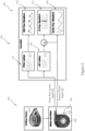
- FIG. 2 illustrates an exemplary heart pump system 200 according to some embodiments that may be configured to carry out method 100 of Figure 1 to estimate left ventricular pressure waveform, VAD flow waveform, and aortic pressure waveform.
- Heart pump system 200 comprises a left ventricular heart pump 202 and a controller 203.
- the pump 202 can be configured similar to an LVAD described in U.S. Patent Publication 2015/0290374 ; U.S. Patent Publication 2014/0188148 ; U.S. Patent No.: 9,091,271 ; U.S. Patent No. 8,794,989 , U.S. Patent No. 8,682,431 ; and/or U.S. Patent No. 8,894,561 .
- the heart pump 202 includes a housing 204.
- Housing 204 encloses a motor 206 and rotor 208.
- Housing 204 may also house a pressure sensor 210.
- pressure sensor 210 may be wired directly to the motor 206. While pressure sensor 210 is illustrated as positioned in the outflow of heart pump 202, in other embodiments, pressure sensor 210 may be positioned in the inflow of heart pump 202.
- Controller 203 may be an on-board controller of heart pump 202 or may be an external controller (e.g., coupled to the heart pump 202 through a percutaneous cable, wirelessly, or the like). Controller 203 may be operably coupled with the motor 206 and the pressure sensor 210 and may receive a rotor drive current signal 212 and a pressure sensor signal 214 from the heart pump 202. With the received rotor drive current signal 212, the controller 203 may estimate a pump flow by accessing a lookup table 216 associating the received current signal (I) to pump flow rate (Q).
- Figure 3 illustrates an exemplary I-Q curve lookup table 300.
- rotor rpm and/or hematocrit may be used, in addition with or alternatively to, current signal to provide an accurate flow rate calculation.
- the controller 203 may estimate a VAD flow waveform 218. Additionally, with the received rotor drive current signal 212, the controller 203 may also estimate a differential pressure across the pump by accessing a lookup table 220 associating the received current signal (I) to differential pressure across the pump (dP).
- the rotor rpm and/or hematocrit may be used, in addition with or alternatively to, rotor current signal to provide an accurate differential pressure measurement.
- hall effect sensor signals may be used to provide rotor positional information which may also be a pressure dependent phenomenon. Accordingly, rotor positional information and/or hall effect sensor signals may be used in addition, or alternatively, to rotor current, rotor rpm, and/or hematocrit to provide accurate differential pressure measurements.
- US Patent Application No. 15/214,099 describes systems and methods that use hall effect sensors to provide rotor positional information, which may be used with embodiments of the present disclosure to provide differential pressure measurements, ventricular pressure measurements, and proxies thereto. In some embodiments, both rotor current signal and positional information may be used to provide accurate differential pressure measurements.
- rotor current signal may be more accurate for a first range, and positional information may be more accurate for a second range.
- Figure 4 illustrates an exemplary I-H curve lookup table 400.
- heart rate, start of systole, and/or start of diastole may be identified using the methods and systems described in US Patent Application No. 15/041,716 , and the pump speed may be modulated accordingly based on one or more of those identified parameters.
- the controller 203 may calculate the left ventricular pressure waveform 222 by subtracting the estimated differential pressures from the received pressure sensor signal 214.
- the controller 203 may associate the pressure sensor signal 214 with an aortic pressure waveform 224 when the outflow of the heart pump 202 is coupled with the aorta of the patient.
- the controller 203 may output the VAD flow waveform 218, the left ventricular pressure waveform 222, and/or the aortic pressure waveform 224 to a user or clinician.
- other clinical parameters may be derived, such as: systolic arterial pressure, diastolic arterial pressure, mean arterial pressure, systemic resistance estimation, aortic compliance estimation, end diastolic pressure (LV filling pressure), end systolic pressure, LV contractility estimation, degree of aortic valve opening, stroke volume and cardiac output estimation. Accordingly, these waveforms could be run through subsequent algorithms to calculate added clinical parameters of interest (e.g., cardiac output, heart rate, etc.).
- the controller 203 may also be configured to adjust the pumping operation of the pump in response to the estimated VAD flow waveform 218, the left ventricular pressure waveform 222, and/or the aortic pressure waveform 224.
- the left ventricular pressure waveform 222 may be associated with a heart rate of a patient, thereby providing patient activity information.
- the heart rate may be automatically calculated by analyzing the rate of left ventricular pressure change in the estimated left ventricular pressure waveform 222 which can also indicates the start of systole.
- a threshold rate of left ventricular pressure change may be used to identify individual heart beats in the calculated left ventricular pressure waveform.
- a pumping operation of a heart pump 202 may be increased (during increased heart rate/activity) or decreased (during decreased heart rate/activity) in response. This may be particularly advantageous as separate patient heart rate sensor or activity monitor may not be needed, thereby possibly reducing complexity and power consumption of a system 200.
- a left ventricular contractility estimate may be estimated based on the left ventricular pressure waveform.
- the contractility estimate may be associated with a gradient of a train of the left ventricular pressure waveform.
- the measured pressure may act as a proxy for one or more other clinical parameters, including but not limited to filling pressure, systolic arterial pressure, diastolic arterial pressure, mean arterial pressure, systemic resistance estimation, aortic compliance estimation, end diastolic pressure, end systolic pressure, LV contractility estimation, degree of aortic valve opening, and/or stroke volume and cardiac output estimation.
- a left ventricular pressure waveform and an aortic pressure waveform may be used to calculate one or more of the above parameters.
- heart pump 202 is generally illustrated as a centrifugal flow heart pump, it should be understood that heart pump 202 may have other configurations.
- heart pump 202 may be an axial flow blood pump or a mixed flow blood pump.
- Pressure sensor may be interrogated at a fast rate ( ⁇ 50 Hz) in combination with rotor torque measurements to provide real-time waveforms for LV pressure, VAD flow, and aortic pressure.
- pressure sensor 210 may be integrated in the inflow of heart pump 202.
- Figure 5 illustrates an exemplary heart pump system 500 that includes a pump 502 and an external controller 504.
- the pump 502 and the external controller 504 may be operably connected to one another (e.g., by a percutaneous cable 506 or the like).
- the pump 502 may include an inflow 508 coupled to a chamber of the heart and an outflow 510 coupled with an aorta of the patient.
- the heart pump system 500 may further include a pressure sensor 512 along a portion of the inflow 508 of the heart pump 502. While inflow 508 is illustrated as coupled to the left ventricle, it should be understood that inflow 508 may be coupled to other chambers of the heart, such as the right ventricle or the left atrium. Depending on the implantation location, a pump 502 may be switched to alternative pre-programmed configurations for measuring particular heart parameters (e.g., right ventricular pressure waveforms, left atrium pressure waveforms, associated filling pressures/contractility, etc.).
- heart parameters e.g., right ventricular pressure waveforms, left atrium pressure waveforms, associated filling pressures/contractility, etc.
- the pressure sensor 210 may be connected via flying lead (wired).
- the sensor 210 could be directly wired to the motor electronics and the sensor 210 itself may be well protected from damage during use.
- the volute/outflow is typically less prone to tissue buildup/fouling than the LV or pump inflow.
- the sensor 210 may be located anywhere from the volute to the aorta.
- heart pump 202 is generally described for implantation in the left ventricle and for estimation of left ventricular parameters, but heart pump 202 may also be configured to couple with other portions of the heart.
- heart pump 202 may couple with the right ventricle, as illustrated in Figure 10 , or the left atrium, as illustrated in Figure 11 .
- the controller 203 may be switched to different pre-programmed configurations depending on the implantation location, so that the signal processing output is associated with the correct physiological parameters. For example, if the heart pump 202 is directly cannulated to the right ventricle, it may be programmed to output the right ventricular pressure waveform and/or the pulmonary arterial pressure waveform using similar signal processing described above. Similarly, if the heart pump 202 is directly cannulated to the left atrium, it may be programmed to output the left atrial pressure waveform using similar signal processing described above.
- a pressure differential across the pump may be received from a plurality of pressure sensors of the heart pump in the alternative to (or in addition to) computing the pressure differential based on a rotor drive current signal.
- Figure 6 illustrates an exemplary heart pump system 600.
- System 600 includes a pump 602 and an external controller 604.
- the pump 602 and the external controller 604 may be operably connected to one another (e.g., by a percutaneous cable 606 or the like).
- the pump 602 may include an inflow 608 coupled to a chamber of the heart (illustrated as the left ventricle, but other chambers may be cannulated by inflow 608) and an outflow 610.
- the inflow 608 may include an upstream pressure sensor 612 and a downstream pressure 614.
- the upstream and downstream pressure sensors 612, 614 may provide differential pressure information between the upstream and downstream pressure sensors 612, 614 and may also provide flow information. Further, the two sensors 612, 614 may provide more accurate pressure measurements and may help calibrate measurements to account for sensor drift. In some embodiments, where the inflow has sufficient hydraulic resistance therethrough, the pressure sensors 612, 614 may provide flow information.
- FIG. 7 illustrates another exemplary heart pump system 600a.
- Heart pump system 600a is similar to system 600 of Figure 6 , except upstream pressure sensor 612a is positioned along the inflow 608 and the downstream pressure sensor 614a is positioned along the outflow 610.
- the upstream and downstream pressure sensors 612a, 614a may provide differential pressure information between the upstream and downstream pressure sensors 612a, 614a and may also provide flow information. Further, the two sensors 612a, 614a may provide more accurate pressure measurements and may help calibrate measurements to account for sensor drift.
- the pressure sensors 612a, 614a may provide flow information.
- FIG 8 illustrates another exemplary heart pump system 600b.
- Heart pump system 600b is similar to system 600 of Figure 6 , except upstream pressure sensor 612b is positioned along the outflow 610 and the downstream pressure sensor 614b is positioned along the outflow 610 downstream from upstream pressure sensor 612b.
- the upstream and downstream pressure sensors 612b, 614b may provide differential pressure information between the upstream and downstream pressure sensors 612b, 614b and may also provide flow information. Further, the two sensors 612b, 614b may provide more accurate pressure measurements and may help calibrate measurements to account for sensor drift. In some embodiments, where the outflow has sufficient hydraulic resistance therethrough, the pressure sensors 612b, 614b may provide flow information.
- FIG 9 illustrates another exemplary heart pump system 600c.
- Heart pump system 600c is similar to the system 600 of Figure 6 but may further include a pressure sensor 800 that is configured to be implanted within the pulmonary artery of the patient.
- the heart pump system 600c does not include pressure sensors integrated with the heart pump 602.
- the pressure sensor 800 may be operably coupled (wired or wirelessly) with pump 602 to transmit pressure measurements from the pulmonary artery.
- the pump 602 or external controller 604 may analyze the pulmonary arterial pressure waveform and may estimate a left atrial pressure waveform or left ventricular pressure waveform based on the pulmonary arterial pressure waveform.
- the ventricular pressure may serve as a proxy for pulmonary arterial pressure.
- One or more computing devices may be adapted to provide desired functionality by accessing software instructions rendered in a computer-readable form.
- any suitable programming, scripting, or other type of language or combinations of languages may be used to implement the teachings contained herein.
- software need not be used exclusively, or at all.
- some embodiments of the methods and systems set forth herein may also be implemented by hard-wired logic or other circuitry, including but not limited to application-specific circuits. Combinations of computer-executed software and hard-wired logic or other circuitry may be suitable as well.
- Embodiments of the methods disclosed herein may be executed by one or more suitable computing devices.
- Such system(s) may comprise one or more computing devices adapted to perform one or more embodiments of the methods disclosed herein.
- such devices may access one or more computer -readable media that embody computer-readable instructions which, when executed by at least one computer, cause the at least one computer to implement one or more embodiments of the methods of the present subject matter.
- the computing device(s) may comprise circuitry that renders the device(s) operative to implement one or more of the methods of the present subject matter.
- Any suitable computer-readable medium or media may be used to implement or practice the presently-disclosed subject matter, including but not limited to, diskettes, drives, and other magnetic-based storage media, optical storage media, including disks (e.g., CD-ROMS, DVD-ROMS, variants thereof, etc.), flash, RAM, ROM, and other memory devices, and the like.
Landscapes
- Health & Medical Sciences (AREA)
- Heart & Thoracic Surgery (AREA)
- Engineering & Computer Science (AREA)
- Life Sciences & Earth Sciences (AREA)
- Cardiology (AREA)
- Public Health (AREA)
- General Health & Medical Sciences (AREA)
- Veterinary Medicine (AREA)
- Hematology (AREA)
- Biomedical Technology (AREA)
- Animal Behavior & Ethology (AREA)
- Mechanical Engineering (AREA)
- Anesthesiology (AREA)
- Medical Informatics (AREA)
- Molecular Biology (AREA)
- Biophysics (AREA)
- Physics & Mathematics (AREA)
- Pathology (AREA)
- Surgery (AREA)
- Vascular Medicine (AREA)
- Physiology (AREA)
- Computer Networks & Wireless Communication (AREA)
- Measuring Pulse, Heart Rate, Blood Pressure Or Blood Flow (AREA)
Description
- Heart disease is a growing epidemic in the United States that can lead to heart failure. Heart failure is characterized as a progressive, downward spiral in heart function. In particular, cardiac injury can cause cardiac dysfunction, which results in reduced cardiac output. Some results of reduced cardiac output are endothelial dysfunction, neurohormonal activation, renal impairment, and vasoconstriction. These results can lead to fluid retention and increased systemic vascular resistance. An increase in systemic vascular resistance can create increased cardiac load which can cause further cardiac dysfunction. Thus a cycle of further cardiac dysfunction can be established.
-
WO 2016/001284 A2 relates to a method for determining an outlet pressure on an outlet of a heart support system. Said method consists of the following steps: An inlet pressure adjacent to an inlet of the heart support system is determined; a pressure difference between the inlet and the outlet of the heart support system is estimated; the outlet pressure is determined from the inlet pressure and the pressure difference. The document also relates to a heart support system for carrying out a method of said type.WO 2016/001284 further discloses a blood pump system comprising: a blood pump comprising an inlet and an outlet, a pressure sensor coupled with the outlet or the inlet of the blood pump; a controller operably coupled with the blood pump and the pressure sensor, the controller configured to: calculate, with the differential pressure: a pressure at the inlet of the blood pump when a pressure sensor is at the outlet, or a pressure at the outlet of the blood pump when a pressure sensor is at the inlet, and generate a desired data waveform from the calculated differential pressure. - Although there are various treatments proposed and being developed for treating heart failure, such systems are generally limited to the hospital setting or at least require the patient to be very limited in mobility if not completely confined to a bed. Some patients have turned to implantable blood pumps, such as ventricular assist devices (VAD), for assisting in heart pumping or effectively replacing the natural heart's function. Most patients recover in a way where they improve in functional class, however, only a small percentage of patients exhibit restoration to the point of explant and the number of hearts available for heart transplant is insufficient to meet demand. As such, the blood pumps are typically required for life. Accordingly, it may be advantageous to further improve blood pump devices, systems, and methods to coordinate pumping functions and to monitor patient physiological parameters during the long term implantation (e.g., destination therapy or bridge to transplantation) of the implantable blood pump so there is continuing need to improve pumps and LVAD therapy. Here, there is need for pressure reading to better provide therapy and/or actively adjust pump parameters based on the patient. For example, a patient may recover over time and the pump can be adjusted accordingly. Optionally, the pump may be adjusted for patient exercise or activity.
- The present invention relates to a blood pump system as defined in claim 1. The dependent claims define preferred embodiments of the blood pump system. In some not claimed embodiments, a method of hemodynamic monitoring is provided for a patient having an implanted heart pump. In further embodiments, a heart pump is provided that may monitor physiological parameters of the patient and may adjust pumping (e.g., speed, mode, flow rate, or the like) in response to the monitored parameters and/or may report the monitored parameters to a physician.
- Many rotary blood pumps may estimate flow through the heart pump, for example, by sensing the electrical current required to drive the rotor at a particular speed. This information may be beneficial for clinicians for determining changes in pump performance associated with a physiological state (e.g., suction detection, patient hypertension, etc.). However, the pump flow rate information alone may be of limited value in diagnosing the patient's hemodynamic state and/or determining if the heart pump is providing adequate flow support (or too much or too little). Patients may have dramatically different cardiac output needs and these needs may change depending on a number of factors (e.g., rest, exercise, stress, left ventricular recovery, time of day, etc.).
- Cardiovascular pressure measurements can provide a host of valuable data that is directly applicable for determining a patient's hemodynamic state and optimizing blood pump settings. For example, a physician may want to specifically tailor a pump flow rate or pump speed depending on patient characteristics. To determine the appropriate flow rate or speed, the physician may benefit from additional information, such as the left ventricular pressure, pulmonary arterial pressure, etc. There are a number of potential sensor devices and locations applicable to the present invention. In particular, real time high speed (e.g., ~50 Hz) pressure measurements of the left ventricle and the aorta may be particularly valuable for left ventricular assist device (LVAD) applications. With such measurements, other clinical parameters may be derived, such as systolic arterial pressure, diastolic arterial pressure, mean arterial pressure, systemic resistance estimation, aortic compliance estimation, end diastolic pressure (LV filling pressure), end systolic pressure, LV contractility estimation, degree of aortic valve opening, stroke volume and/or cardiac output estimation. Additionally, pressure measurements may be used to increase the accuracy of flow rate estimations based on drive current, similar to the concepts described in
US Patent Application No. 15/212,721 . - In some not claimed embodiments of the present invention, a method for hemodynamic monitoring of a patient may be provided. The method may include receiving a differential pressure across the heart pump having an inflow and an outflow. A pressure measurement may be received from a pressure sensor positioned in the inflow or the outflow of the heart pump. A data waveform of interest may be calculated from the differential pressure across the heart pump and the pressure measurement from the pressure sensor positioned in the inflow or the outflow of the heart pump.
- In some embodiments, the calculated data waveform of interest may be outputted (e.g., to a patient or a clinician). In some embodiments, a pumping of the heart pump may be adjusted in response to the calculated data waveform. In some embodiments, the pressure sensor is positioned in the outflow of the heart pump. The differential pressure across the heart pump may be calculated based on a rotor drive current associated with the heart pump. In some embodiments, the data waveform of interest comprises a left ventricular pressure waveform and the left ventricular pressure waveform may be calculated by subtracting the differential pressure from the pressure measurement.
- In further aspects of the present invention, a blood pump system may be provided. The system may include a blood pump comprising an inlet and an outlet. A pressure sensor may be provided that is coupled with the inlet or the outlet of the blood pump. A controller operably coupled with the blood pump and the pressure sensor may be configured to receive a differential pressure across the blood pump and a pressure measurement from the pressure sensor. The controller may be configured to calculate a data waveform of interest from the differential pressure across the blood pump and the pressure measurement from the pressure sensor.
- In some embodiments, the controller is configured to output the calculated data waveform. Optionally, the controller is configured to adjust a pumping of the heart pump in response to the calculated data waveform. In some embodiments, the sensor is positioned on the outflow of the blood pump. In some embodiments, the controller calculates the differential pressure across the blood pump based on a rotor driver current associated with the blood pump. In certain embodiments, the data waveform of interest comprises a left ventricular pressure waveform and the left ventricular pressure waveform may be calculated by subtracting the differential pressure from the pressure measurement.
- Embodiments of the disclosure covered by this patent are defined by the claims below, not this summary. This summary is a high-level overview of various aspects of the invention and introduces some of the concepts that are further described in the Detailed Description section below. This summary is not intended to identify key or essential features of the claimed subject matter, nor is it intended to be used in isolation to determine the scope of the claimed subject matter. The subject matter should be understood by reference to appropriate portions of the entire specification of this patent, any or all drawings, and each claim.
- The disclosure will be better understood upon reading the following description and examining the figures which accompany it. These figures are provided by way of illustration only and are in no way limiting on the invention.
- Further details, aspects, and embodiments of the invention will be described by way of example only and with reference to the drawings. In the drawings, like reference numbers are used to identify like or functionally similar elements. Elements in the figures are illustrated for simplicity and clarity and have not necessarily been drawn to scale.
-
Figure 1 illustrates an exemplary method according to some embodiments. -
Figure 2 illustrates an exemplary system according to some embodiments. -
Figure 3 illustrates an exemplary I-Q curve lookup table. -
Figure 4 illustrates an exemplary I-H curve lookup table. -
Figure 5 illustrates an exemplary heart pump system according to some embodiments. -
Figure 6 illustrates another exemplary heart pump system according to some embodiments. -
Figure 7 illustrates another exemplary heart pump system according to some embodiments. -
Figure 8 illustrates another exemplary heart pump system according to some embodiments. -
Figure 9 illustrates another exemplary heart pump system according to some embodiments. -
Figure 10 illustrates an exemplary implantation location of a heart pump according to some embodiments. -
Figure 11 illustrates another exemplary implantation location of a heart pump according to some embodiments. -
Figure 1 illustrates anexemplary method 100 for estimating physiological waveforms of interest of a patient with a blood pump according to some embodiments. Themethod 100 may include receiving a rotor drive current signal of theblood pump 102. A pressure sensor signal that is associated with an input or an output of the blood pump may also be received 104. A differential pressure across the blood pump may be calculated based on the received rotor drivecurrent signal 106. A physiological waveform of the patient may be calculated based on the received pressure sensor signal and the differential pressure across theblood pump 108. Thereafter, the calculated physiological waveform may be outputted 110. Additionally, a pumping operation of the blood pump may be adjusted in response to the calculated physiological waveform 112. -
Method 100 may be used to estimate the left ventricular pressure waveform. Additionally, the aortic pressure waveform may be calculated separate from or in addition to the left ventricular pressure waveform. With such measurements, other clinical parameters may be derived, such as: systolic arterial pressure, diastolic arterial pressure, mean arterial pressure, systemic resistance estimation, aortic compliance estimation, end diastolic pressure (LV filling pressure), end systolic pressure, LV contractility estimation, degree of aortic valve opening, stroke volume and cardiac output estimation. While generally discussed as estimating parameters associated with the left ventricle, it should be understood that themethod 100 is applicable to measuring parameters associated with other chambers of the heart (e.g., right ventricle, left atrium, etc.), depending on where the heart pump is implanted. -
Figure 2 illustrates an exemplaryheart pump system 200 according to some embodiments that may be configured to carry outmethod 100 ofFigure 1 to estimate left ventricular pressure waveform, VAD flow waveform, and aortic pressure waveform.Heart pump system 200 comprises a leftventricular heart pump 202 and acontroller 203. In some embodiments, thepump 202 can be configured similar to an LVAD described inU.S. Patent Publication 2015/0290374 ;U.S. Patent Publication 2014/0188148 ;U.S. Patent No.: 9,091,271 U.S. Patent No. 8,794,989 ,U.S. Patent No. 8,682,431 ; and/orU.S. Patent No. 8,894,561 . Theheart pump 202 includes ahousing 204.Housing 204 encloses amotor 206 androtor 208.Housing 204 may also house apressure sensor 210. Optionally,pressure sensor 210 may be wired directly to themotor 206. Whilepressure sensor 210 is illustrated as positioned in the outflow ofheart pump 202, in other embodiments,pressure sensor 210 may be positioned in the inflow ofheart pump 202. -
Controller 203 may be an on-board controller ofheart pump 202 or may be an external controller (e.g., coupled to theheart pump 202 through a percutaneous cable, wirelessly, or the like).Controller 203 may be operably coupled with themotor 206 and thepressure sensor 210 and may receive a rotor drivecurrent signal 212 and apressure sensor signal 214 from theheart pump 202. With the received rotor drivecurrent signal 212, thecontroller 203 may estimate a pump flow by accessing a lookup table 216 associating the received current signal (I) to pump flow rate (Q).Figure 3 illustrates an exemplary I-Q curve lookup table 300. In some embodiments, rotor rpm and/or hematocrit may be used, in addition with or alternatively to, current signal to provide an accurate flow rate calculation. By continuously estimating pump flow, thecontroller 203 may estimate aVAD flow waveform 218. Additionally, with the received rotor drivecurrent signal 212, thecontroller 203 may also estimate a differential pressure across the pump by accessing a lookup table 220 associating the received current signal (I) to differential pressure across the pump (dP). In some embodiments, the rotor rpm and/or hematocrit may be used, in addition with or alternatively to, rotor current signal to provide an accurate differential pressure measurement. In some embodiments which use magnetic levitation rotors, hall effect sensor signals may be used to provide rotor positional information which may also be a pressure dependent phenomenon. Accordingly, rotor positional information and/or hall effect sensor signals may be used in addition, or alternatively, to rotor current, rotor rpm, and/or hematocrit to provide accurate differential pressure measurements.US Patent Application No. 15/214,099 describes systems and methods that use hall effect sensors to provide rotor positional information, which may be used with embodiments of the present disclosure to provide differential pressure measurements, ventricular pressure measurements, and proxies thereto. In some embodiments, both rotor current signal and positional information may be used to provide accurate differential pressure measurements. For example, rotor current signal may be more accurate for a first range, and positional information may be more accurate for a second range.Figure 4 illustrates an exemplary I-H curve lookup table 400. In some embodiments, heart rate, start of systole, and/or start of diastole may be identified using the methods and systems described inUS Patent Application No. 15/041,716 , and the pump speed may be modulated accordingly based on one or more of those identified parameters. Thecontroller 203 may calculate the leftventricular pressure waveform 222 by subtracting the estimated differential pressures from the receivedpressure sensor signal 214. Additionally, thecontroller 203 may associate thepressure sensor signal 214 with anaortic pressure waveform 224 when the outflow of theheart pump 202 is coupled with the aorta of the patient. Thecontroller 203 may output theVAD flow waveform 218, the leftventricular pressure waveform 222, and/or theaortic pressure waveform 224 to a user or clinician. As mentioned above, with such measurements, other clinical parameters may be derived, such as: systolic arterial pressure, diastolic arterial pressure, mean arterial pressure, systemic resistance estimation, aortic compliance estimation, end diastolic pressure (LV filling pressure), end systolic pressure, LV contractility estimation, degree of aortic valve opening, stroke volume and cardiac output estimation. Accordingly, these waveforms could be run through subsequent algorithms to calculate added clinical parameters of interest (e.g., cardiac output, heart rate, etc.). - The
controller 203 may also be configured to adjust the pumping operation of the pump in response to the estimatedVAD flow waveform 218, the leftventricular pressure waveform 222, and/or theaortic pressure waveform 224. For example, in some embodiments, the leftventricular pressure waveform 222 may be associated with a heart rate of a patient, thereby providing patient activity information. The heart rate may be automatically calculated by analyzing the rate of left ventricular pressure change in the estimated leftventricular pressure waveform 222 which can also indicates the start of systole. In some embodiments, a threshold rate of left ventricular pressure change may be used to identify individual heart beats in the calculated left ventricular pressure waveform. With changes in heart rate or activity of a patient, a pumping operation of aheart pump 202 may be increased (during increased heart rate/activity) or decreased (during decreased heart rate/activity) in response. This may be particularly advantageous as separate patient heart rate sensor or activity monitor may not be needed, thereby possibly reducing complexity and power consumption of asystem 200. - In addition, a left ventricular contractility estimate may be estimated based on the left ventricular pressure waveform. For example, the contractility estimate may be associated with a gradient of a train of the left ventricular pressure waveform.
- The measured pressure may act as a proxy for one or more other clinical parameters, including but not limited to filling pressure, systolic arterial pressure, diastolic arterial pressure, mean arterial pressure, systemic resistance estimation, aortic compliance estimation, end diastolic pressure, end systolic pressure, LV contractility estimation, degree of aortic valve opening, and/or stroke volume and cardiac output estimation. For example, a left ventricular pressure waveform and an aortic pressure waveform may be used to calculate one or more of the above parameters.
- While
heart pump 202 is generally illustrated as a centrifugal flow heart pump, it should be understood thatheart pump 202 may have other configurations. For example, in some embodiments,heart pump 202 may be an axial flow blood pump or a mixed flow blood pump. - Pressure sensor may be interrogated at a fast rate (~50 Hz) in combination with rotor torque measurements to provide real-time waveforms for LV pressure, VAD flow, and aortic pressure. Further, as mentioned above
pressure sensor 210 may be integrated in the inflow ofheart pump 202. For example,Figure 5 illustrates an exemplaryheart pump system 500 that includes apump 502 and anexternal controller 504. Thepump 502 and theexternal controller 504 may be operably connected to one another (e.g., by apercutaneous cable 506 or the like). Thepump 502 may include aninflow 508 coupled to a chamber of the heart and anoutflow 510 coupled with an aorta of the patient. Theheart pump system 500 may further include apressure sensor 512 along a portion of theinflow 508 of theheart pump 502. Whileinflow 508 is illustrated as coupled to the left ventricle, it should be understood thatinflow 508 may be coupled to other chambers of the heart, such as the right ventricle or the left atrium. Depending on the implantation location, apump 502 may be switched to alternative pre-programmed configurations for measuring particular heart parameters (e.g., right ventricular pressure waveforms, left atrium pressure waveforms, associated filling pressures/contractility, etc.). - Alternatively, the
pressure sensor 210 may be connected via flying lead (wired). In some embodiments, it may be advantageous to integrate thesensor 210 directly into the pump housing. For example, thesensor 210 could be directly wired to the motor electronics and thesensor 210 itself may be well protected from damage during use. In addition, the volute/outflow is typically less prone to tissue buildup/fouling than the LV or pump inflow. In such embodiments, thesensor 210 may be located anywhere from the volute to the aorta. - Many traditional sensors could be used, including MEMS, strain gauges, piezo-based sensors, capacitive sensors, transonic, ultrasound Doppler, or the like.
U.S. Provisional Patent Application No. 62/194,700 U.S. Provisional Patent Application No. 62/194,608 - Additionally,
heart pump 202 is generally described for implantation in the left ventricle and for estimation of left ventricular parameters, butheart pump 202 may also be configured to couple with other portions of the heart. For example, in some embodiments,heart pump 202 may couple with the right ventricle, as illustrated inFigure 10 , or the left atrium, as illustrated inFigure 11 . Thecontroller 203 may be switched to different pre-programmed configurations depending on the implantation location, so that the signal processing output is associated with the correct physiological parameters. For example, if theheart pump 202 is directly cannulated to the right ventricle, it may be programmed to output the right ventricular pressure waveform and/or the pulmonary arterial pressure waveform using similar signal processing described above. Similarly, if theheart pump 202 is directly cannulated to the left atrium, it may be programmed to output the left atrial pressure waveform using similar signal processing described above. - In still further embodiments of the present disclosure, a pressure differential across the pump may be received from a plurality of pressure sensors of the heart pump in the alternative to (or in addition to) computing the pressure differential based on a rotor drive current signal. For example,
Figure 6 illustrates an exemplaryheart pump system 600.System 600 includes apump 602 and anexternal controller 604. Thepump 602 and theexternal controller 604 may be operably connected to one another (e.g., by apercutaneous cable 606 or the like). Thepump 602 may include aninflow 608 coupled to a chamber of the heart (illustrated as the left ventricle, but other chambers may be cannulated by inflow 608) and anoutflow 610. Theinflow 608 may include anupstream pressure sensor 612 and adownstream pressure 614. The upstream anddownstream pressure sensors downstream pressure sensors sensors pressure sensors -
Figure 7 illustrates another exemplaryheart pump system 600a.Heart pump system 600a is similar tosystem 600 ofFigure 6 , exceptupstream pressure sensor 612a is positioned along theinflow 608 and thedownstream pressure sensor 614a is positioned along theoutflow 610. The upstream anddownstream pressure sensors downstream pressure sensors sensors pressure sensors -
Figure 8 illustrates another exemplaryheart pump system 600b.Heart pump system 600b is similar tosystem 600 ofFigure 6 , except upstream pressure sensor 612b is positioned along theoutflow 610 and thedownstream pressure sensor 614b is positioned along theoutflow 610 downstream from upstream pressure sensor 612b. The upstream anddownstream pressure sensors 612b, 614b may provide differential pressure information between the upstream anddownstream pressure sensors 612b, 614b and may also provide flow information. Further, the twosensors 612b, 614b may provide more accurate pressure measurements and may help calibrate measurements to account for sensor drift. In some embodiments, where the outflow has sufficient hydraulic resistance therethrough, thepressure sensors 612b, 614b may provide flow information. -
Figure 9 illustrates another exemplaryheart pump system 600c.Heart pump system 600c is similar to thesystem 600 ofFigure 6 but may further include apressure sensor 800 that is configured to be implanted within the pulmonary artery of the patient. In some embodiments, theheart pump system 600c does not include pressure sensors integrated with theheart pump 602. Thepressure sensor 800, however, may be operably coupled (wired or wirelessly) withpump 602 to transmit pressure measurements from the pulmonary artery. Thepump 602 orexternal controller 604 may analyze the pulmonary arterial pressure waveform and may estimate a left atrial pressure waveform or left ventricular pressure waveform based on the pulmonary arterial pressure waveform. In some embodiments, the ventricular pressure may serve as a proxy for pulmonary arterial pressure. - One or more computing devices may be adapted to provide desired functionality by accessing software instructions rendered in a computer-readable form. When software is used, any suitable programming, scripting, or other type of language or combinations of languages may be used to implement the teachings contained herein. However, software need not be used exclusively, or at all. For example, some embodiments of the methods and systems set forth herein may also be implemented by hard-wired logic or other circuitry, including but not limited to application-specific circuits. Combinations of computer-executed software and hard-wired logic or other circuitry may be suitable as well.
- Embodiments of the methods disclosed herein may be executed by one or more suitable computing devices. Such system(s) may comprise one or more computing devices adapted to perform one or more embodiments of the methods disclosed herein. As noted above, such devices may access one or more computer -readable media that embody computer-readable instructions which, when executed by at least one computer, cause the at least one computer to implement one or more embodiments of the methods of the present subject matter. Additionally or alternatively, the computing device(s) may comprise circuitry that renders the device(s) operative to implement one or more of the methods of the present subject matter.
- Any suitable computer-readable medium or media may be used to implement or practice the presently-disclosed subject matter, including but not limited to, diskettes, drives, and other magnetic-based storage media, optical storage media, including disks (e.g., CD-ROMS, DVD-ROMS, variants thereof, etc.), flash, RAM, ROM, and other memory devices, and the like.
- In the description above, various embodiments of the present invention are described. For purposes of explanation, specific configurations and details are set forth in order to provide a thorough understanding of the embodiments.
- The use of the terms "a" and "an" and "the" and similar referents in the context of describing the invention (especially in the context of the following claims) are to be construed to cover both the singular and the plural, unless otherwise indicated herein or clearly contradicted by context. The terms "comprising," "having," "including," and "containing" are to be construed as open-ended terms (i.e., meaning "including, but not limited to,") unless otherwise noted. The term "connected" is to be construed as partly or wholly contained within, attached to, or joined together, even if there is something intervening. Recitation of ranges of values herein are merely intended to serve as a shorthand method of referring individually to each separate value falling within the range, unless otherwise indicated herein, and each separate value is incorporated into the specification as if it were individually recited herein. All methods described herein can be performed in any suitable order unless otherwise indicated herein or otherwise clearly contradicted by context. The use of any and all examples, or exemplary language (e.g., "such as") provided herein, is intended merely to better illuminate embodiments of the invention and does not pose a limitation on the scope of the invention unless otherwise claimed. No language in the specification should be construed as indicating any non-claimed element as essential to the practice of the invention.
- Preferred embodiments of this invention are described herein, including the best mode known to the inventors for carrying out the invention. Variations of those preferred embodiments may become apparent to those of ordinary skill in the art upon reading the foregoing description. The inventors expect skilled artisans to employ such variations as appropriate, and the inventors intend for the invention to be practiced otherwise than as specifically described herein but as defined by the appended claims.
Claims (15)
- A blood pump system (200) comprising:a blood pump (202) comprising an inlet and an outlet,a pressure sensor (210) coupled with the outlet or the inlet of the blood pump (202);a controller (203) operably coupled with the blood pump (202) and the pressure sensor (210), the controller (203) configured to:determine a differential pressure across the blood pump (202) based on a rotation rate of a rotor of the blood pump and a magnitude of an electrical current used to rotate the rotor at the rotation rate;calculate, with the differential pressure:1) a pressure at the inlet of the blood pump (202) when a pressure sensor (210) is at the outlet, or2) a pressure at the outlet of the blood pump (202) when a pressure sensor (210) is at the inlet, andgenerate a desired data waveform from the calculated differential pressure.
- The blood pump system of claim 1, wherein the controller (203) is configured to output the desired data waveform.
- The blood pump system of any of claims 1 or 2, wherein the controller (203) is configured to adjust a pumping of the blood pump (202) in response to the desired data waveform.
- The blood pump system of any of claims 1-3, wherein the controller (203) is configured to adjust a pumping mode of the blood pump (202) in response to the desired data waveform.
- The blood pump system of any of claims 1-4, wherein the controller (203) adjusts a pump rotor speed in response to the desired data waveform.
- The blood pump system of any of claims 1-5, wherein the pressure sensor (210) is integrated into a housing (204) of the blood pump (202) at the outlet of the blood pump (202).
- The blood pump system of any of claims 1-5, wherein the pressure sensor (210) is positioned within an outflow graft coupled to the blood pump (202).
- The blood pump system of any of claims 1-5, wherein the pressure sensor (210) is positioned within an inlet cannula of the blood pump (202).
- The blood pump system of any of claims 1-8, wherein the controller (203) is configured to calculate the differential pressure by accessing a lookup table (220) associating a rotor drive current with differential pressure.
- The blood pump system of any of claims 1-9, wherein the desired data waveform comprises a left ventricular pressure waveform (222), and wherein the left ventricular pressure waveform (222) is calculated by subtracting the differential pressure from the calculated differential pressure.
- The blood pump system of claim 10, wherein the controller (203) is configured to calculate a heart rate associated with a patient by analyzing a rate of left ventricular pressure change in the left ventricular pressure waveform (222).
- The blood pump system of claim 10, wherein the controller (203) is configured to identify individual heart beats in the left ventricular pressure waveform (222) using a threshold rate of left ventricular pressure change.
- The blood pump system of claim 11, wherein the controller (203) is configured to adjust a pumping of the blood pump (202) in response to changes in the heart rate, the pumping being increased during a determined increased heart rate and the pumping being decreased during a determined decreased heart rate.
- The blood pump system of any of claims 1-12, wherein the outflow of the blood pump (202) is configured to be coupled with an aorta, and wherein the desired data waveform comprises an aortic pressure waveform (224).
- The blood pump system of any of claims 1-14, further comprising a pressure sensor (800) configured to be implanted within a pulmonary artery.
Priority Applications (1)
| Application Number | Priority Date | Filing Date | Title |
|---|---|---|---|
| EP24177400.9A EP4424357A1 (en) | 2017-03-29 | 2018-03-28 | Pressure sensing ventricular assist devices |
Applications Claiming Priority (2)
| Application Number | Priority Date | Filing Date | Title |
|---|---|---|---|
| US201762478492P | 2017-03-29 | 2017-03-29 | |
| PCT/US2018/024947 WO2018183568A1 (en) | 2017-03-29 | 2018-03-28 | Pressure sensing ventricular assist devices and methods of use |
Related Child Applications (1)
| Application Number | Title | Priority Date | Filing Date |
|---|---|---|---|
| EP24177400.9A Division EP4424357A1 (en) | 2017-03-29 | 2018-03-28 | Pressure sensing ventricular assist devices |
Publications (2)
| Publication Number | Publication Date |
|---|---|
| EP3600478A1 EP3600478A1 (en) | 2020-02-05 |
| EP3600478B1 true EP3600478B1 (en) | 2024-06-26 |
Family
ID=62002444
Family Applications (2)
| Application Number | Title | Priority Date | Filing Date |
|---|---|---|---|
| EP18718314.0A Active EP3600478B1 (en) | 2017-03-29 | 2018-03-28 | Pressure sensing ventricular assist devices |
| EP24177400.9A Pending EP4424357A1 (en) | 2017-03-29 | 2018-03-28 | Pressure sensing ventricular assist devices |
Family Applications After (1)
| Application Number | Title | Priority Date | Filing Date |
|---|---|---|---|
| EP24177400.9A Pending EP4424357A1 (en) | 2017-03-29 | 2018-03-28 | Pressure sensing ventricular assist devices |
Country Status (3)
| Country | Link |
|---|---|
| US (4) | US10835654B2 (en) |
| EP (2) | EP3600478B1 (en) |
| WO (1) | WO2018183568A1 (en) |
Families Citing this family (66)
| Publication number | Priority date | Publication date | Assignee | Title |
|---|---|---|---|---|
| US11065436B2 (en) | 2017-03-29 | 2021-07-20 | Tc1 Llc | Communication methods and architecture for heart treatment systems |
| WO2018183568A1 (en) * | 2017-03-29 | 2018-10-04 | Tc1 Llc | Pressure sensing ventricular assist devices and methods of use |
| WO2018183565A1 (en) | 2017-03-29 | 2018-10-04 | Harjes Daniel I | Adjusting protocol based on irregular heart rhythm |
| EP3634528B1 (en) | 2017-06-07 | 2023-06-07 | Shifamed Holdings, LLC | Intravascular fluid movement devices, systems, and methods of use |
| US11511103B2 (en) | 2017-11-13 | 2022-11-29 | Shifamed Holdings, Llc | Intravascular fluid movement devices, systems, and methods of use |
| EP3746149B1 (en) | 2018-02-01 | 2025-08-06 | Shifamed Holdings, LLC | Intravascular blood pumps |
| US11517740B2 (en) | 2018-03-15 | 2022-12-06 | Tc1 Llc | Methods for controlling a left ventricular assist device |
| EP3768341A1 (en) | 2018-03-19 | 2021-01-27 | Tc1 Llc | Coordinated ventricular assist and cardiac rhythm management devices and methods |
| DE102018207594A1 (en) | 2018-05-16 | 2019-11-21 | Kardion Gmbh | Rotor, magnetic coupling device, electric motor for a cardiac assist system, pump unit for a cardiac assist system and method for manufacturing a rotor |
| DE102018207575A1 (en) | 2018-05-16 | 2019-11-21 | Kardion Gmbh | Magnetic face turning coupling for the transmission of torques |
| DE102018208539A1 (en) | 2018-05-30 | 2019-12-05 | Kardion Gmbh | A motor housing module for sealing an engine compartment of a motor of a cardiac assist system and cardiac assistance system and method for mounting a cardiac assist system |
| DE102018208538A1 (en) | 2018-05-30 | 2019-12-05 | Kardion Gmbh | Intravascular blood pump and process for the production of electrical conductors |
| DE102018208541A1 (en) | 2018-05-30 | 2019-12-05 | Kardion Gmbh | Axial pump for a cardiac assist system and method of making an axial pump for a cardiac assist system |
| DE102018208549A1 (en) | 2018-05-30 | 2019-12-05 | Kardion Gmbh | Electronic module for a cardiac assist system and method for manufacturing an electronic module for a cardiac assist system |
| DE102018208550A1 (en) | 2018-05-30 | 2019-12-05 | Kardion Gmbh | A lead device for directing blood flow to a cardiac assist system, cardiac assist system, and method of making a lead device |
| DE102018208931A1 (en) | 2018-06-06 | 2019-12-12 | Kardion Gmbh | Apparatus for determining cardiac output for a cardiac assist system, cardiac assistive system and method for determining cardiac output |
| DE102018208936A1 (en) | 2018-06-06 | 2019-12-12 | Kardion Gmbh | Determining device and method for determining a viscosity of a fluid |
| DE102018208870A1 (en) | 2018-06-06 | 2019-12-12 | Kardion Gmbh | A method of determining a fluid volume flow through an implanted vascular support system |
| DE102018208879A1 (en) | 2018-06-06 | 2020-01-30 | Kardion Gmbh | Method for determining a total fluid volume flow in the area of an implanted, vascular support system |
| DE102018208862A1 (en) | 2018-06-06 | 2019-12-12 | Kardion Gmbh | Implantable vascular support system |
| DE102018208892A1 (en) | 2018-06-06 | 2019-12-12 | Kardion Gmbh | A sensor head device for a minimally invasive cardiac assist system and method of manufacturing a sensor head device for a cardiac assist system |
| DE102018208945A1 (en) | 2018-06-06 | 2019-12-12 | Kardion Gmbh | An analysis device and method for analyzing a viscosity of a fluid |
| DE102018208913A1 (en) | 2018-06-06 | 2019-12-12 | Kardion Gmbh | A method of operating an implanted ventricular assist device |
| DE102018208899A1 (en) | 2018-06-06 | 2019-12-12 | Kardion Gmbh | A method for determining the speed of sound in a fluid in the region of an implanted vascular support system |
| DE102018208929A1 (en) | 2018-06-06 | 2019-12-12 | Kardion Gmbh | A method of determining a flow rate of fluid flowing through an implanted vascular support system |
| DE102018208933A1 (en) | 2018-06-06 | 2019-12-12 | Kardion Gmbh | A method of determining a flow rate of fluid flowing through an implanted vascular support system |
| DE102018210076A1 (en) | 2018-06-21 | 2019-12-24 | Kardion Gmbh | Method and device for detecting a state of wear of a cardiac support system, method and device for operating a cardiac support system and cardiac support system |
| DE102018210058A1 (en) | 2018-06-21 | 2019-12-24 | Kardion Gmbh | Stator blade device for guiding the flow of a fluid flowing out of an outlet opening of a heart support system, heart support system with stator blade device, method for operating a stator blade device and manufacturing method |
| DE102018211297A1 (en) | 2018-07-09 | 2020-01-09 | Kardion Gmbh | Cardiac support system and method for monitoring the integrity of a support structure of a cardiac support system |
| DE102018211328A1 (en) | 2018-07-10 | 2020-01-16 | Kardion Gmbh | Impeller housing for an implantable vascular support system |
| DE102018211327A1 (en) | 2018-07-10 | 2020-01-16 | Kardion Gmbh | Impeller for an implantable vascular support system |
| US11241570B2 (en) | 2018-07-17 | 2022-02-08 | Tc1 Llc | Systems and methods for inertial sensing for VAD diagnostics and closed loop control |
| WO2020028537A1 (en) | 2018-07-31 | 2020-02-06 | Shifamed Holdings, Llc | Intravascaular blood pumps and methods of use |
| ES3055124T3 (en) | 2018-08-07 | 2026-02-10 | Kardion Gmbh | Bearing device for a heart support system, and method for rinsing a space in a bearing device for a heart support system |
| DE102018213350A1 (en) | 2018-08-08 | 2020-02-13 | Kardion Gmbh | Device and method for monitoring a patient's health |
| EP3856275B1 (en) * | 2018-09-27 | 2023-01-18 | Heartware, Inc. | Map estimation on vad patients |
| WO2020073047A1 (en) | 2018-10-05 | 2020-04-09 | Shifamed Holdings, Llc | Intravascular blood pumps and methods of use |
| WO2020093084A1 (en) * | 2018-11-09 | 2020-05-14 | St Vincent's Hospital Sydney Limited | Ventricular function determination |
| US11666281B2 (en) * | 2019-02-28 | 2023-06-06 | Medtronic, Inc. | Detection of hypertension in LVAD patients using speed change |
| WO2021011473A1 (en) | 2019-07-12 | 2021-01-21 | Shifamed Holdings, Llc | Intravascular blood pumps and methods of manufacture and use |
| US11654275B2 (en) | 2019-07-22 | 2023-05-23 | Shifamed Holdings, Llc | Intravascular blood pumps with struts and methods of use and manufacture |
| US12465748B2 (en) | 2019-08-07 | 2025-11-11 | Supira Medical, Inc. | Catheter blood pumps and collapsible pump housings |
| US11724089B2 (en) | 2019-09-25 | 2023-08-15 | Shifamed Holdings, Llc | Intravascular blood pump systems and methods of use and control thereof |
| EP4501393A3 (en) | 2019-09-25 | 2025-04-09 | Shifamed Holdings, LLC | Catheter blood pumps and collapsible pump housings |
| WO2021062260A1 (en) | 2019-09-25 | 2021-04-01 | Shifamed Holdings, Llc | Catheter blood pumps and collapsible blood conduits |
| CN114929328B (en) | 2019-10-25 | 2025-03-14 | Tc1有限责任公司 | Blood circulation support system including a controller and a plurality of sensors |
| EP4072650A4 (en) | 2019-12-11 | 2024-01-10 | Shifamed Holdings, LLC | DESCENDING AORTA AND VEINA CAVA BLOOD PUMPS |
| EP4077947A4 (en) | 2019-12-19 | 2024-01-10 | Shifamed Holdings, LLC | Intravascular blood pumps, motors, and fluid control |
| DE102020102474A1 (en) | 2020-01-31 | 2021-08-05 | Kardion Gmbh | Pump for conveying a fluid and method for manufacturing a pump |
| EP4120893B1 (en) * | 2020-03-18 | 2026-02-11 | Scandinavian Real Heart AB | Pressure sensor arrangement and method |
| JP7744043B2 (en) | 2020-09-14 | 2025-09-25 | カルディオン ゲーエムベーハー | Cardiovascular assist pump having an impeller with variable flow area |
| CN114504728A (en) * | 2020-11-17 | 2022-05-17 | 苏州恒瑞宏远医疗科技有限公司 | Sensor for heart blood pump and heart blood pump |
| US12589237B2 (en) | 2020-11-20 | 2026-03-31 | Kardion Gmbh | Mechanical circulatory support system with guidewire aid |
| WO2022197725A1 (en) * | 2021-03-17 | 2022-09-22 | 3R Life Sciences Corporation | Sutureless inflow cannula assembly for connecting ventricular assist devices to human circulation |
| US12472301B2 (en) * | 2021-08-13 | 2025-11-18 | 3Ive Labs, Llc | Negative pressure therapy system and methods |
| TW202327685A (en) * | 2021-09-10 | 2023-07-16 | 德商阿比奥梅德歐洲有限公司 | System and method for ventricular assistance support during extracorporeal membrane oxygenation |
| CN113769260B (en) * | 2021-09-16 | 2024-09-27 | 苏州心岭迈德医疗科技有限公司 | Auxiliary blood pumping system |
| US12502524B2 (en) | 2021-12-03 | 2025-12-23 | Kardion Gmbh | Cardiac pump with optical fiber for laser doppler |
| CN115779260A (en) * | 2022-11-24 | 2023-03-14 | 上海炫脉医疗科技有限公司 | System and method for estimating the position of an interventional blood pump |
| CN115957435A (en) * | 2022-12-20 | 2023-04-14 | 上海炫脉医疗科技有限公司 | Method and device for measuring blood pressure at outlet of blood pump |
| CN118662775A (en) * | 2023-03-14 | 2024-09-20 | 上海焕擎医疗科技有限公司 | Control device, method and ventricular assist system based on ventricular assist device |
| CN116650829B (en) * | 2023-05-22 | 2025-09-02 | 清华大学 | Interventional pump based on micro pressure sensor and its implantation position determination method |
| WO2025072043A1 (en) * | 2023-09-25 | 2025-04-03 | Boston Scientific Scimed, Inc. | Circulatory support devices, systems, and methods |
| CN117018434B (en) * | 2023-10-07 | 2023-12-26 | 心擎医疗(苏州)股份有限公司 | Interventional pump position determination method, device, control equipment and ventricular assist device |
| CN117899349B (en) * | 2024-03-18 | 2024-06-04 | 生命盾医疗技术(苏州)有限公司 | A ventricular assist device control method, device, electronic device and storage medium |
| SE2450759A1 (en) * | 2024-07-04 | 2026-01-05 | Scandinavian Real Heart | Integrated Differential Pressure Sensor for Artificial Heart Control |
Family Cites Families (80)
| Publication number | Priority date | Publication date | Assignee | Title |
|---|---|---|---|---|
| US3911897A (en) | 1974-04-05 | 1975-10-14 | Jr Frank A Leachman | Heart assist device |
| US5139517A (en) | 1989-11-08 | 1992-08-18 | Corral David F | Orthotopic intraventricular heart pump |
| EP0532144B1 (en) | 1991-09-12 | 1999-02-24 | BIOTRONIK Mess- und Therapiegeräte GmbH & Co Ingenieurbüro Berlin | Cardiac therapy system |
| US5503615A (en) | 1994-08-26 | 1996-04-02 | Goldstein; Bernard | Implantable cardiac ventricular assist device and controller thereof |
| US5888242A (en) | 1996-11-01 | 1999-03-30 | Nimbus, Inc. | Speed control system for implanted blood pumps |
| US6111520A (en) | 1997-04-18 | 2000-08-29 | Georgia Tech Research Corp. | System and method for the wireless sensing of physical properties |
| US6889082B2 (en) | 1997-10-09 | 2005-05-03 | Orqis Medical Corporation | Implantable heart assist system and method of applying same |
| US6176822B1 (en) * | 1998-03-31 | 2001-01-23 | Impella Cardiotechnik Gmbh | Intracardiac blood pump |
| US6278379B1 (en) | 1998-04-02 | 2001-08-21 | Georgia Tech Research Corporation | System, method, and sensors for sensing physical properties |
| DE59915262D1 (en) | 1998-07-10 | 2011-06-01 | Levitronix Llc | Method for determining the pressure loss and the flow through a pump |
| US8244370B2 (en) | 2001-04-13 | 2012-08-14 | Greatbatch Ltd. | Band stop filter employing a capacitor and an inductor tank circuit to enhance MRI compatibility of active medical devices |
| US6585635B1 (en) | 1999-09-17 | 2003-07-01 | Core Medical, Inc. | Method and system for pericardial modification |
| GB0023412D0 (en) | 2000-09-23 | 2000-11-08 | Khaghani Asghar | Aortic counterpulsator |
| SE523852C2 (en) | 2001-04-10 | 2004-05-25 | Azad Al-Najjar | Heart prosthesis |
| US8712544B2 (en) | 2001-04-13 | 2014-04-29 | Greatbatch Ltd. | Electromagnetic shield for a passive electronic component in an active medical device implantable lead |
| US7853325B2 (en) | 2001-04-13 | 2010-12-14 | Greatbatch Ltd. | Cylindrical bandstop filters for medical lead systems |
| US8145324B1 (en) | 2001-04-13 | 2012-03-27 | Greatbatch Ltd. | Implantable lead bandstop filter employing an inductive coil with parasitic capacitance to enhance MRI compatibility of active medical devices |
| US6643420B2 (en) | 2001-12-28 | 2003-11-04 | Digital Optics Corp. | Optical subassembly |
| US7396327B2 (en) | 2002-01-07 | 2008-07-08 | Micromed Technology, Inc. | Blood pump system and method of operation |
| US6855115B2 (en) | 2002-01-22 | 2005-02-15 | Cardiomems, Inc. | Implantable wireless sensor for pressure measurement within the heart |
| US7029433B2 (en) | 2002-03-16 | 2006-04-18 | Chang Sheldon S | Device for cardiac restoration |
| US6772011B2 (en) | 2002-08-20 | 2004-08-03 | Thoratec Corporation | Transmission of information from an implanted medical device |
| AU2002951685A0 (en) | 2002-09-30 | 2002-10-17 | Ventrassist Pty Ltd | Physiological demand responsive control system |
| US7245117B1 (en) | 2004-11-01 | 2007-07-17 | Cardiomems, Inc. | Communicating with implanted wireless sensor |
| US20050071001A1 (en) | 2003-09-30 | 2005-03-31 | Robert Jarvik | Artificial heart power and control system |
| WO2005042089A1 (en) | 2003-10-31 | 2005-05-12 | Sunshine Heart Company Pty Ltd | Synchronisation control system |
| WO2005051838A2 (en) | 2003-11-19 | 2005-06-09 | Transoma Medical, Inc. | Feedback control of ventricular assist devices |
| PL1715902T3 (en) | 2004-01-08 | 2017-01-31 | Sullivan, Paul Joseph | Nondestructive fluid transfer device |
| US8271093B2 (en) | 2004-09-17 | 2012-09-18 | Cardiac Pacemakers, Inc. | Systems and methods for deriving relative physiologic measurements using a backend computing system |
| EP1876945B1 (en) | 2005-03-04 | 2012-12-05 | CardioMems, Inc. | Communicating with an implanted wireless sensor |
| EP2471450A1 (en) | 2005-10-14 | 2012-07-04 | Nanostim, Inc. | Leadless cardiac pacemaker and system |
| US20070142923A1 (en) | 2005-11-04 | 2007-06-21 | Ayre Peter J | Control systems for rotary blood pumps |
| US8224462B2 (en) | 2005-11-11 | 2012-07-17 | Greatbatch Ltd. | Medical lead system utilizing electromagnetic bandstop filters |
| CN101472627B (en) | 2006-01-30 | 2013-05-08 | 国立成功大学 | Dual-pulsation bi-ventricular assist device |
| AU2007201127B2 (en) | 2006-03-23 | 2012-02-09 | Thoratec Corporation | System For Preventing Diastolic Heart Failure |
| US20100268333A1 (en) | 2009-04-16 | 2010-10-21 | Gohean Jeffrey R | System and method for controlling pump |
| DE102006035548B4 (en) | 2006-07-27 | 2009-02-12 | Deutsches Zentrum für Luft- und Raumfahrt e.V. | artificial heart |
| US7963905B2 (en) | 2006-10-11 | 2011-06-21 | Thoratec Corporation | Control system for a blood pump |
| WO2008154387A1 (en) | 2007-06-06 | 2008-12-18 | Worldheart Corporation | Wearable vad controller with reserve battery |
| US8562507B2 (en) * | 2009-02-27 | 2013-10-22 | Thoratec Corporation | Prevention of aortic valve fusion |
| EP2525870B1 (en) | 2010-01-19 | 2019-03-13 | Heartware, Inc. | Physiologically responsive vad |
| DE102010011798B4 (en) * | 2010-03-17 | 2017-07-13 | Fresenius Medical Care Deutschland Gmbh | Method and device for determining the pressure or volume flow of medical fluids |
| CN102939117B (en) | 2010-04-02 | 2015-12-02 | 阳光心脏有限公司 | Combination heart assist system, method and apparatus |
| AT14334U1 (en) | 2010-05-09 | 2015-08-15 | Labstyle Innovation Ltd | Liquid device and method of use thereof |
| US9091271B2 (en) | 2010-08-20 | 2015-07-28 | Thoratec Corporation | Implantable blood pump |
| EP3020426B1 (en) | 2010-09-24 | 2017-12-27 | Tc1 Llc | Generating artificial pulse |
| US8901775B2 (en) | 2010-12-10 | 2014-12-02 | Everheart Systems, Inc. | Implantable wireless power system |
| WO2012051237A1 (en) | 2010-10-12 | 2012-04-19 | Nanostim, Inc. | Temperature sensor for a leadless cardiac pacemaker |
| US8608636B2 (en) | 2010-11-12 | 2013-12-17 | Libraheart, Inc.V | Ventricular assist device cannula and ventricular assist device including the same |
| US8794989B2 (en) | 2010-12-08 | 2014-08-05 | Thoratec Corporation | Modular driveline |
| US8876686B2 (en) | 2011-02-18 | 2014-11-04 | Vascor, Inc | Control of blood flow assist systems |
| WO2012135775A1 (en) | 2011-04-01 | 2012-10-04 | Medtronic, Inc. | Heart failure monitoring |
| US9205274B2 (en) | 2011-04-19 | 2015-12-08 | Pacesetter, Inc. | Devices, systems, and methods for characterizing a tachycardia and/or selecting treatment for a tachycardia using results of a dominant frequency analysis |
| EP2570143B1 (en) | 2011-09-14 | 2014-01-15 | BIOTRONIK SE & Co. KG | Implantable cardiac therapy device |
| US8682431B2 (en) | 2012-01-24 | 2014-03-25 | Thoratec Corporation | Driveline cable assembly |
| EP2822614B1 (en) | 2012-03-05 | 2016-12-28 | Thoratec Corporation | Modular implantable medical pump |
| WO2013184932A1 (en) | 2012-06-06 | 2013-12-12 | Heartware, Inc. | Speed change algorithm for a continuous flow blood pump |
| US20150174307A1 (en) | 2012-07-19 | 2015-06-25 | Regents Of The University Of Minnesota | Cardiac assist device with pulse wave analysis |
| CN104768589B (en) | 2012-09-05 | 2017-04-19 | 哈特威尔公司 | VAD with integrated flow sensor |
| US9090271B2 (en) | 2012-10-24 | 2015-07-28 | Progress Rail Services Corporation | System and method for characterizing dragging equipment |
| US20140188148A1 (en) | 2012-12-27 | 2014-07-03 | Pieter W.C.J. le Blanc | Surgical tunneler |
| EP2796156A1 (en) | 2013-04-24 | 2014-10-29 | ETH Zurich | Biomedical apparatus for pumping blood of a human or an animal patient through a secondary intra- or extracorporeal blood circuit |
| US10052420B2 (en) | 2013-04-30 | 2018-08-21 | Tc1 Llc | Heart beat identification and pump speed synchronization |
| US9592327B2 (en) | 2013-09-06 | 2017-03-14 | Cardiac Pacemakers, Inc. | Systems and methods for heart failure management |
| CN104511060A (en) | 2013-10-03 | 2015-04-15 | 北京精密机电控制设备研究所 | Blood pump control system and blood pump system |
| EP3131596B1 (en) | 2014-04-15 | 2020-07-22 | Tc1 Llc | Methods and systems for controlling a blood pump |
| EP2962710A1 (en) * | 2014-07-03 | 2016-01-06 | Berlin Heart GmbH | Method and heart support system for determining an outlet pressure |
| US9623161B2 (en) | 2014-08-26 | 2017-04-18 | Tc1 Llc | Blood pump and method of suction detection |
| US20160058930A1 (en) | 2014-08-26 | 2016-03-03 | Thoratec Corporation | Blood pump and method of suction detection |
| CN107405489B (en) | 2015-02-24 | 2021-03-12 | 心脏器械股份有限公司 | Blood Pumps for Bradycardia Treatment |
| EP3324840A4 (en) | 2015-07-20 | 2019-03-20 | Tc1 Llc | TENSIOMETER FOR FLOW ESTIMATION |
| WO2017015268A1 (en) | 2015-07-20 | 2017-01-26 | Thoratec Corporation | Flow estimation using hall-effect sensors |
| WO2017117185A1 (en) | 2015-12-28 | 2017-07-06 | Heartware, Inc. | Pump motor control with adaptive startup |
| CN108430531B (en) | 2015-12-28 | 2020-09-22 | 心脏器械股份有限公司 | VAD Controller Tester |
| CN108883126B (en) | 2016-02-12 | 2024-10-01 | 马林克罗特医疗产品知识产权公司 | Use and monitoring of inhaled nitric oxide with left ventricular assist devices |
| EP3213781A1 (en) * | 2016-03-02 | 2017-09-06 | ETH Zurich | Biomedical apparatus with a pressure-regulated blood pump |
| US20180050348A1 (en) | 2016-08-19 | 2018-02-22 | Mark Whitney | Quench water hydrocyclone |
| WO2018183568A1 (en) * | 2017-03-29 | 2018-10-04 | Tc1 Llc | Pressure sensing ventricular assist devices and methods of use |
| WO2018183565A1 (en) | 2017-03-29 | 2018-10-04 | Harjes Daniel I | Adjusting protocol based on irregular heart rhythm |
| US11065436B2 (en) | 2017-03-29 | 2021-07-20 | Tc1 Llc | Communication methods and architecture for heart treatment systems |
-
2018
- 2018-03-28 WO PCT/US2018/024947 patent/WO2018183568A1/en not_active Ceased
- 2018-03-28 US US15/939,105 patent/US10835654B2/en active Active
- 2018-03-28 EP EP18718314.0A patent/EP3600478B1/en active Active
- 2018-03-28 EP EP24177400.9A patent/EP4424357A1/en active Pending
-
2020
- 2020-09-22 US US17/028,687 patent/US11779234B2/en active Active
-
2023
- 2023-09-01 US US18/460,185 patent/US12383156B2/en active Active
-
2025
- 2025-07-22 US US19/276,642 patent/US20250344962A1/en active Pending
Also Published As
| Publication number | Publication date |
|---|---|
| US20230404421A1 (en) | 2023-12-21 |
| US20180280601A1 (en) | 2018-10-04 |
| US10835654B2 (en) | 2020-11-17 |
| WO2018183568A1 (en) | 2018-10-04 |
| EP4424357A1 (en) | 2024-09-04 |
| EP3600478A1 (en) | 2020-02-05 |
| US11779234B2 (en) | 2023-10-10 |
| US20250344962A1 (en) | 2025-11-13 |
| US12383156B2 (en) | 2025-08-12 |
| US20210001025A1 (en) | 2021-01-07 |
Similar Documents
| Publication | Publication Date | Title |
|---|---|---|
| US12383156B2 (en) | Pressure sensing ventricular assist devices and methods of use | |
| US12397147B2 (en) | Method and apparatus for calibration and use in estimating blood flow in an intravascular blood pump | |
| AU2019290143B2 (en) | Systems and methods for system identification | |
| EP4201467B1 (en) | Blood pump | |
| CN104822400B (en) | Method of controlling the rate of a ventricular assist device (VAD) and ventricular assist device | |
| EP2585129B1 (en) | Fluid delivery system and method for monitoring fluid delivery system | |
| JPWO1999033502A1 (en) | Blood flow circulation assist device using continuous flow blood pump and diagnostic device for blood flow circulation status in living body | |
| JP4769937B2 (en) | Centrifugal pump flow rate and head measurement device, and circulating state evaluation device for pulsating circulation system | |
| JP2017536193A (en) | Mean arterial pressure estimation | |
| JP2012519035A (en) | Prevention of aortic valve adhesion | |
| US20100121133A1 (en) | Apparatus and methods for measuring pressure and flow in cardiac assist devices and peripheral vasculature | |
| WO2014064267A1 (en) | Control system for a cardiac assist device | |
| JP3864944B2 (en) | Blood flow circulatory assist device using continuous flow blood pump and diagnostic device for blood flow circulatory state of living body | |
| HK40080443A (en) | Method and apparatus for calibration and use in estimating blood flow in an intravascular blood pump | |
| HK40051050A (en) | Systems for system identification | |
| HK40051050B (en) | Systems for system identification | |
| HK40038497B (en) | Method and apparatus for calibration and use in estimating blood flow in an intravascular blood pump | |
| HK40038497A (en) | Method and apparatus for calibration and use in estimating blood flow in an intravascular blood pump | |
| HK40026713A (en) | Blood pump |
Legal Events
| Date | Code | Title | Description |
|---|---|---|---|
| STAA | Information on the status of an ep patent application or granted ep patent |
Free format text: STATUS: UNKNOWN |
|
| STAA | Information on the status of an ep patent application or granted ep patent |
Free format text: STATUS: THE INTERNATIONAL PUBLICATION HAS BEEN MADE |
|
| PUAI | Public reference made under article 153(3) epc to a published international application that has entered the european phase |
Free format text: ORIGINAL CODE: 0009012 |
|
| STAA | Information on the status of an ep patent application or granted ep patent |
Free format text: STATUS: REQUEST FOR EXAMINATION WAS MADE |
|
| 17P | Request for examination filed |
Effective date: 20191028 |
|
| AK | Designated contracting states |
Kind code of ref document: A1 Designated state(s): AL AT BE BG CH CY CZ DE DK EE ES FI FR GB GR HR HU IE IS IT LI LT LU LV MC MK MT NL NO PL PT RO RS SE SI SK SM TR |
|
| AX | Request for extension of the european patent |
Extension state: BA ME |
|
| DAV | Request for validation of the european patent (deleted) | ||
| DAX | Request for extension of the european patent (deleted) | ||
| STAA | Information on the status of an ep patent application or granted ep patent |
Free format text: STATUS: EXAMINATION IS IN PROGRESS |
|
| 17Q | First examination report despatched |
Effective date: 20211217 |
|
| P01 | Opt-out of the competence of the unified patent court (upc) registered |
Effective date: 20230616 |
|
| REG | Reference to a national code |
Ref country code: DE Ref legal event code: R079 Free format text: PREVIOUS MAIN CLASS: A61M0001100000 Ipc: A61M0060178000 Ref country code: DE Ref legal event code: R079 Ref document number: 602018070984 Country of ref document: DE Free format text: PREVIOUS MAIN CLASS: A61M0001100000 Ipc: A61M0060178000 |
|
| GRAP | Despatch of communication of intention to grant a patent |
Free format text: ORIGINAL CODE: EPIDOSNIGR1 |
|
| STAA | Information on the status of an ep patent application or granted ep patent |
Free format text: STATUS: GRANT OF PATENT IS INTENDED |
|
| RIC1 | Information provided on ipc code assigned before grant |
Ipc: A61M 60/88 20210101ALI20240111BHEP Ipc: A61M 60/546 20210101ALI20240111BHEP Ipc: A61M 60/531 20210101ALI20240111BHEP Ipc: A61M 60/422 20210101ALI20240111BHEP Ipc: A61M 60/237 20210101ALI20240111BHEP Ipc: A61M 60/232 20210101ALI20240111BHEP Ipc: A61M 60/221 20210101ALI20240111BHEP Ipc: A61M 60/178 20210101AFI20240111BHEP |
|
| INTG | Intention to grant announced |
Effective date: 20240129 |
|
| GRAS | Grant fee paid |
Free format text: ORIGINAL CODE: EPIDOSNIGR3 |
|
| GRAA | (expected) grant |
Free format text: ORIGINAL CODE: 0009210 |
|
| STAA | Information on the status of an ep patent application or granted ep patent |
Free format text: STATUS: THE PATENT HAS BEEN GRANTED |
|
| AK | Designated contracting states |
Kind code of ref document: B1 Designated state(s): AL AT BE BG CH CY CZ DE DK EE ES FI FR GB GR HR HU IE IS IT LI LT LU LV MC MK MT NL NO PL PT RO RS SE SI SK SM TR |
|
| REG | Reference to a national code |
Ref country code: GB Ref legal event code: FG4D |
|
| REG | Reference to a national code |
Ref country code: CH Ref legal event code: EP |
|
| REG | Reference to a national code |
Ref country code: DE Ref legal event code: R096 Ref document number: 602018070984 Country of ref document: DE |
|
| PG25 | Lapsed in a contracting state [announced via postgrant information from national office to epo] |
Ref country code: BG Free format text: LAPSE BECAUSE OF FAILURE TO SUBMIT A TRANSLATION OF THE DESCRIPTION OR TO PAY THE FEE WITHIN THE PRESCRIBED TIME-LIMIT Effective date: 20240626 |
|
| PG25 | Lapsed in a contracting state [announced via postgrant information from national office to epo] |
Ref country code: FI Free format text: LAPSE BECAUSE OF FAILURE TO SUBMIT A TRANSLATION OF THE DESCRIPTION OR TO PAY THE FEE WITHIN THE PRESCRIBED TIME-LIMIT Effective date: 20240626 Ref country code: HR Free format text: LAPSE BECAUSE OF FAILURE TO SUBMIT A TRANSLATION OF THE DESCRIPTION OR TO PAY THE FEE WITHIN THE PRESCRIBED TIME-LIMIT Effective date: 20240626 |
|
| REG | Reference to a national code |
Ref country code: LT Ref legal event code: MG9D |
|
| PG25 | Lapsed in a contracting state [announced via postgrant information from national office to epo] |
Ref country code: GR Free format text: LAPSE BECAUSE OF FAILURE TO SUBMIT A TRANSLATION OF THE DESCRIPTION OR TO PAY THE FEE WITHIN THE PRESCRIBED TIME-LIMIT Effective date: 20240927 |
|
| PG25 | Lapsed in a contracting state [announced via postgrant information from national office to epo] |
Ref country code: LV Free format text: LAPSE BECAUSE OF FAILURE TO SUBMIT A TRANSLATION OF THE DESCRIPTION OR TO PAY THE FEE WITHIN THE PRESCRIBED TIME-LIMIT Effective date: 20240626 |
|
| REG | Reference to a national code |
Ref country code: NL Ref legal event code: MP Effective date: 20240626 |
|
| PG25 | Lapsed in a contracting state [announced via postgrant information from national office to epo] |
Ref country code: NO Free format text: LAPSE BECAUSE OF FAILURE TO SUBMIT A TRANSLATION OF THE DESCRIPTION OR TO PAY THE FEE WITHIN THE PRESCRIBED TIME-LIMIT Effective date: 20240926 Ref country code: LV Free format text: LAPSE BECAUSE OF FAILURE TO SUBMIT A TRANSLATION OF THE DESCRIPTION OR TO PAY THE FEE WITHIN THE PRESCRIBED TIME-LIMIT Effective date: 20240626 Ref country code: HR Free format text: LAPSE BECAUSE OF FAILURE TO SUBMIT A TRANSLATION OF THE DESCRIPTION OR TO PAY THE FEE WITHIN THE PRESCRIBED TIME-LIMIT Effective date: 20240626 Ref country code: GR Free format text: LAPSE BECAUSE OF FAILURE TO SUBMIT A TRANSLATION OF THE DESCRIPTION OR TO PAY THE FEE WITHIN THE PRESCRIBED TIME-LIMIT Effective date: 20240927 Ref country code: FI Free format text: LAPSE BECAUSE OF FAILURE TO SUBMIT A TRANSLATION OF THE DESCRIPTION OR TO PAY THE FEE WITHIN THE PRESCRIBED TIME-LIMIT Effective date: 20240626 Ref country code: BG Free format text: LAPSE BECAUSE OF FAILURE TO SUBMIT A TRANSLATION OF THE DESCRIPTION OR TO PAY THE FEE WITHIN THE PRESCRIBED TIME-LIMIT Effective date: 20240626 Ref country code: RS Free format text: LAPSE BECAUSE OF FAILURE TO SUBMIT A TRANSLATION OF THE DESCRIPTION OR TO PAY THE FEE WITHIN THE PRESCRIBED TIME-LIMIT Effective date: 20240926 |
|
| PG25 | Lapsed in a contracting state [announced via postgrant information from national office to epo] |
Ref country code: NL Free format text: LAPSE BECAUSE OF FAILURE TO SUBMIT A TRANSLATION OF THE DESCRIPTION OR TO PAY THE FEE WITHIN THE PRESCRIBED TIME-LIMIT Effective date: 20240626 |
|
| REG | Reference to a national code |
Ref country code: AT Ref legal event code: MK05 Ref document number: 1697202 Country of ref document: AT Kind code of ref document: T Effective date: 20240626 |
|
| PG25 | Lapsed in a contracting state [announced via postgrant information from national office to epo] |
Ref country code: NL Free format text: LAPSE BECAUSE OF FAILURE TO SUBMIT A TRANSLATION OF THE DESCRIPTION OR TO PAY THE FEE WITHIN THE PRESCRIBED TIME-LIMIT Effective date: 20240626 |
|
| PG25 | Lapsed in a contracting state [announced via postgrant information from national office to epo] |
Ref country code: PT Free format text: LAPSE BECAUSE OF FAILURE TO SUBMIT A TRANSLATION OF THE DESCRIPTION OR TO PAY THE FEE WITHIN THE PRESCRIBED TIME-LIMIT Effective date: 20241028 |
|
| PG25 | Lapsed in a contracting state [announced via postgrant information from national office to epo] |
Ref country code: PT Free format text: LAPSE BECAUSE OF FAILURE TO SUBMIT A TRANSLATION OF THE DESCRIPTION OR TO PAY THE FEE WITHIN THE PRESCRIBED TIME-LIMIT Effective date: 20241028 |
|
| PG25 | Lapsed in a contracting state [announced via postgrant information from national office to epo] |
Ref country code: PL Free format text: LAPSE BECAUSE OF FAILURE TO SUBMIT A TRANSLATION OF THE DESCRIPTION OR TO PAY THE FEE WITHIN THE PRESCRIBED TIME-LIMIT Effective date: 20240626 |
|
| PG25 | Lapsed in a contracting state [announced via postgrant information from national office to epo] |
Ref country code: EE Free format text: LAPSE BECAUSE OF FAILURE TO SUBMIT A TRANSLATION OF THE DESCRIPTION OR TO PAY THE FEE WITHIN THE PRESCRIBED TIME-LIMIT Effective date: 20240626 |
|
| PG25 | Lapsed in a contracting state [announced via postgrant information from national office to epo] |
Ref country code: IS Free format text: LAPSE BECAUSE OF FAILURE TO SUBMIT A TRANSLATION OF THE DESCRIPTION OR TO PAY THE FEE WITHIN THE PRESCRIBED TIME-LIMIT Effective date: 20241026 Ref country code: AT Free format text: LAPSE BECAUSE OF FAILURE TO SUBMIT A TRANSLATION OF THE DESCRIPTION OR TO PAY THE FEE WITHIN THE PRESCRIBED TIME-LIMIT Effective date: 20240626 |
|
| PG25 | Lapsed in a contracting state [announced via postgrant information from national office to epo] |
Ref country code: CZ Free format text: LAPSE BECAUSE OF FAILURE TO SUBMIT A TRANSLATION OF THE DESCRIPTION OR TO PAY THE FEE WITHIN THE PRESCRIBED TIME-LIMIT Effective date: 20240626 |
|
| PG25 | Lapsed in a contracting state [announced via postgrant information from national office to epo] |
Ref country code: RO Free format text: LAPSE BECAUSE OF FAILURE TO SUBMIT A TRANSLATION OF THE DESCRIPTION OR TO PAY THE FEE WITHIN THE PRESCRIBED TIME-LIMIT Effective date: 20240626 Ref country code: SK Free format text: LAPSE BECAUSE OF FAILURE TO SUBMIT A TRANSLATION OF THE DESCRIPTION OR TO PAY THE FEE WITHIN THE PRESCRIBED TIME-LIMIT Effective date: 20240626 |
|
| PG25 | Lapsed in a contracting state [announced via postgrant information from national office to epo] |
Ref country code: ES Free format text: LAPSE BECAUSE OF FAILURE TO SUBMIT A TRANSLATION OF THE DESCRIPTION OR TO PAY THE FEE WITHIN THE PRESCRIBED TIME-LIMIT Effective date: 20240626 Ref country code: SM Free format text: LAPSE BECAUSE OF FAILURE TO SUBMIT A TRANSLATION OF THE DESCRIPTION OR TO PAY THE FEE WITHIN THE PRESCRIBED TIME-LIMIT Effective date: 20240626 |
|
| PG25 | Lapsed in a contracting state [announced via postgrant information from national office to epo] |
Ref country code: SM Free format text: LAPSE BECAUSE OF FAILURE TO SUBMIT A TRANSLATION OF THE DESCRIPTION OR TO PAY THE FEE WITHIN THE PRESCRIBED TIME-LIMIT Effective date: 20240626 Ref country code: SK Free format text: LAPSE BECAUSE OF FAILURE TO SUBMIT A TRANSLATION OF THE DESCRIPTION OR TO PAY THE FEE WITHIN THE PRESCRIBED TIME-LIMIT Effective date: 20240626 Ref country code: RO Free format text: LAPSE BECAUSE OF FAILURE TO SUBMIT A TRANSLATION OF THE DESCRIPTION OR TO PAY THE FEE WITHIN THE PRESCRIBED TIME-LIMIT Effective date: 20240626 Ref country code: PL Free format text: LAPSE BECAUSE OF FAILURE TO SUBMIT A TRANSLATION OF THE DESCRIPTION OR TO PAY THE FEE WITHIN THE PRESCRIBED TIME-LIMIT Effective date: 20240626 Ref country code: IS Free format text: LAPSE BECAUSE OF FAILURE TO SUBMIT A TRANSLATION OF THE DESCRIPTION OR TO PAY THE FEE WITHIN THE PRESCRIBED TIME-LIMIT Effective date: 20241026 Ref country code: ES Free format text: LAPSE BECAUSE OF FAILURE TO SUBMIT A TRANSLATION OF THE DESCRIPTION OR TO PAY THE FEE WITHIN THE PRESCRIBED TIME-LIMIT Effective date: 20240626 Ref country code: EE Free format text: LAPSE BECAUSE OF FAILURE TO SUBMIT A TRANSLATION OF THE DESCRIPTION OR TO PAY THE FEE WITHIN THE PRESCRIBED TIME-LIMIT Effective date: 20240626 Ref country code: CZ Free format text: LAPSE BECAUSE OF FAILURE TO SUBMIT A TRANSLATION OF THE DESCRIPTION OR TO PAY THE FEE WITHIN THE PRESCRIBED TIME-LIMIT Effective date: 20240626 Ref country code: AT Free format text: LAPSE BECAUSE OF FAILURE TO SUBMIT A TRANSLATION OF THE DESCRIPTION OR TO PAY THE FEE WITHIN THE PRESCRIBED TIME-LIMIT Effective date: 20240626 |
|
| PG25 | Lapsed in a contracting state [announced via postgrant information from national office to epo] |
Ref country code: IT Free format text: LAPSE BECAUSE OF FAILURE TO SUBMIT A TRANSLATION OF THE DESCRIPTION OR TO PAY THE FEE WITHIN THE PRESCRIBED TIME-LIMIT Effective date: 20240626 |
|
| REG | Reference to a national code |
Ref country code: DE Ref legal event code: R097 Ref document number: 602018070984 Country of ref document: DE |
|
| PG25 | Lapsed in a contracting state [announced via postgrant information from national office to epo] |
Ref country code: DK Free format text: LAPSE BECAUSE OF FAILURE TO SUBMIT A TRANSLATION OF THE DESCRIPTION OR TO PAY THE FEE WITHIN THE PRESCRIBED TIME-LIMIT Effective date: 20240626 |
|
| PLBE | No opposition filed within time limit |
Free format text: ORIGINAL CODE: 0009261 |
|
| STAA | Information on the status of an ep patent application or granted ep patent |
Free format text: STATUS: NO OPPOSITION FILED WITHIN TIME LIMIT |
|
| 26N | No opposition filed |
Effective date: 20250327 |
|
| PG25 | Lapsed in a contracting state [announced via postgrant information from national office to epo] |
Ref country code: SE Free format text: LAPSE BECAUSE OF FAILURE TO SUBMIT A TRANSLATION OF THE DESCRIPTION OR TO PAY THE FEE WITHIN THE PRESCRIBED TIME-LIMIT Effective date: 20240626 |
|
| PG25 | Lapsed in a contracting state [announced via postgrant information from national office to epo] |
Ref country code: MC Free format text: LAPSE BECAUSE OF FAILURE TO SUBMIT A TRANSLATION OF THE DESCRIPTION OR TO PAY THE FEE WITHIN THE PRESCRIBED TIME-LIMIT Effective date: 20240626 |
|
| REG | Reference to a national code |
Ref country code: CH Ref legal event code: H13 Free format text: ST27 STATUS EVENT CODE: U-0-0-H10-H13 (AS PROVIDED BY THE NATIONAL OFFICE) Effective date: 20251023 |
|
| PG25 | Lapsed in a contracting state [announced via postgrant information from national office to epo] |
Ref country code: LU Free format text: LAPSE BECAUSE OF NON-PAYMENT OF DUE FEES Effective date: 20250328 |
|
| REG | Reference to a national code |
Ref country code: BE Ref legal event code: MM Effective date: 20250331 |
|
| PG25 | Lapsed in a contracting state [announced via postgrant information from national office to epo] |
Ref country code: FR Free format text: LAPSE BECAUSE OF NON-PAYMENT OF DUE FEES Effective date: 20250331 |
|
| PG25 | Lapsed in a contracting state [announced via postgrant information from national office to epo] |
Ref country code: BE Free format text: LAPSE BECAUSE OF NON-PAYMENT OF DUE FEES Effective date: 20250331 |
|
| PG25 | Lapsed in a contracting state [announced via postgrant information from national office to epo] |
Ref country code: CH Free format text: LAPSE BECAUSE OF NON-PAYMENT OF DUE FEES Effective date: 20250331 |
|
| PG25 | Lapsed in a contracting state [announced via postgrant information from national office to epo] |
Ref country code: IE Free format text: LAPSE BECAUSE OF NON-PAYMENT OF DUE FEES Effective date: 20250328 |
|
| PGFP | Annual fee paid to national office [announced via postgrant information from national office to epo] |
Ref country code: GB Payment date: 20260211 Year of fee payment: 9 |
|
| PGFP | Annual fee paid to national office [announced via postgrant information from national office to epo] |
Ref country code: DE Payment date: 20260213 Year of fee payment: 9 |