EP3599653A1 - Li-ion battery high voltage distribution system architecture - Google Patents
Li-ion battery high voltage distribution system architecture Download PDFInfo
- Publication number
- EP3599653A1 EP3599653A1 EP19176809.2A EP19176809A EP3599653A1 EP 3599653 A1 EP3599653 A1 EP 3599653A1 EP 19176809 A EP19176809 A EP 19176809A EP 3599653 A1 EP3599653 A1 EP 3599653A1
- Authority
- EP
- European Patent Office
- Prior art keywords
- battery pack
- battery
- disconnect mechanism
- lithium
- bus
- Prior art date
- Legal status (The legal status is an assumption and is not a legal conclusion. Google has not performed a legal analysis and makes no representation as to the accuracy of the status listed.)
- Granted
Links
Images



Classifications
-
- H—ELECTRICITY
- H01—ELECTRIC ELEMENTS
- H01M—PROCESSES OR MEANS, e.g. BATTERIES, FOR THE DIRECT CONVERSION OF CHEMICAL ENERGY INTO ELECTRICAL ENERGY
- H01M10/00—Secondary cells; Manufacture thereof
- H01M10/42—Methods or arrangements for servicing or maintenance of secondary cells or secondary half-cells
- H01M10/425—Structural combination with electronic components, e.g. electronic circuits integrated to the outside of the casing
-
- H—ELECTRICITY
- H01—ELECTRIC ELEMENTS
- H01M—PROCESSES OR MEANS, e.g. BATTERIES, FOR THE DIRECT CONVERSION OF CHEMICAL ENERGY INTO ELECTRICAL ENERGY
- H01M10/00—Secondary cells; Manufacture thereof
- H01M10/05—Accumulators with non-aqueous electrolyte
- H01M10/052—Li-accumulators
- H01M10/0525—Rocking-chair batteries, i.e. batteries with lithium insertion or intercalation in both electrodes; Lithium-ion batteries
-
- H—ELECTRICITY
- H01—ELECTRIC ELEMENTS
- H01M—PROCESSES OR MEANS, e.g. BATTERIES, FOR THE DIRECT CONVERSION OF CHEMICAL ENERGY INTO ELECTRICAL ENERGY
- H01M10/00—Secondary cells; Manufacture thereof
- H01M10/42—Methods or arrangements for servicing or maintenance of secondary cells or secondary half-cells
- H01M10/4207—Methods or arrangements for servicing or maintenance of secondary cells or secondary half-cells for several batteries or cells simultaneously or sequentially
-
- H—ELECTRICITY
- H01—ELECTRIC ELEMENTS
- H01M—PROCESSES OR MEANS, e.g. BATTERIES, FOR THE DIRECT CONVERSION OF CHEMICAL ENERGY INTO ELECTRICAL ENERGY
- H01M10/00—Secondary cells; Manufacture thereof
- H01M10/42—Methods or arrangements for servicing or maintenance of secondary cells or secondary half-cells
- H01M10/48—Accumulators combined with arrangements for measuring, testing or indicating the condition of cells, e.g. the level or density of the electrolyte
-
- H—ELECTRICITY
- H01—ELECTRIC ELEMENTS
- H01M—PROCESSES OR MEANS, e.g. BATTERIES, FOR THE DIRECT CONVERSION OF CHEMICAL ENERGY INTO ELECTRICAL ENERGY
- H01M50/00—Constructional details or processes of manufacture of the non-active parts of electrochemical cells other than fuel cells, e.g. hybrid cells
- H01M50/20—Mountings; Secondary casings or frames; Racks, modules or packs; Suspension devices; Shock absorbers; Transport or carrying devices; Holders
- H01M50/204—Racks, modules or packs for multiple batteries or multiple cells
-
- H—ELECTRICITY
- H01—ELECTRIC ELEMENTS
- H01M—PROCESSES OR MEANS, e.g. BATTERIES, FOR THE DIRECT CONVERSION OF CHEMICAL ENERGY INTO ELECTRICAL ENERGY
- H01M50/00—Constructional details or processes of manufacture of the non-active parts of electrochemical cells other than fuel cells, e.g. hybrid cells
- H01M50/20—Mountings; Secondary casings or frames; Racks, modules or packs; Suspension devices; Shock absorbers; Transport or carrying devices; Holders
- H01M50/249—Mountings; Secondary casings or frames; Racks, modules or packs; Suspension devices; Shock absorbers; Transport or carrying devices; Holders specially adapted for aircraft or vehicles, e.g. cars or trains
-
- H—ELECTRICITY
- H01—ELECTRIC ELEMENTS
- H01M—PROCESSES OR MEANS, e.g. BATTERIES, FOR THE DIRECT CONVERSION OF CHEMICAL ENERGY INTO ELECTRICAL ENERGY
- H01M50/00—Constructional details or processes of manufacture of the non-active parts of electrochemical cells other than fuel cells, e.g. hybrid cells
- H01M50/50—Current conducting connections for cells or batteries
- H01M50/572—Means for preventing undesired use or discharge
- H01M50/574—Devices or arrangements for the interruption of current
- H01M50/581—Devices or arrangements for the interruption of current in response to temperature
-
- H—ELECTRICITY
- H01—ELECTRIC ELEMENTS
- H01M—PROCESSES OR MEANS, e.g. BATTERIES, FOR THE DIRECT CONVERSION OF CHEMICAL ENERGY INTO ELECTRICAL ENERGY
- H01M50/00—Constructional details or processes of manufacture of the non-active parts of electrochemical cells other than fuel cells, e.g. hybrid cells
- H01M50/50—Current conducting connections for cells or batteries
- H01M50/572—Means for preventing undesired use or discharge
- H01M50/574—Devices or arrangements for the interruption of current
- H01M50/583—Devices or arrangements for the interruption of current in response to current, e.g. fuses
-
- H—ELECTRICITY
- H01—ELECTRIC ELEMENTS
- H01M—PROCESSES OR MEANS, e.g. BATTERIES, FOR THE DIRECT CONVERSION OF CHEMICAL ENERGY INTO ELECTRICAL ENERGY
- H01M10/00—Secondary cells; Manufacture thereof
- H01M10/42—Methods or arrangements for servicing or maintenance of secondary cells or secondary half-cells
- H01M10/48—Accumulators combined with arrangements for measuring, testing or indicating the condition of cells, e.g. the level or density of the electrolyte
- H01M10/486—Accumulators combined with arrangements for measuring, testing or indicating the condition of cells, e.g. the level or density of the electrolyte for measuring temperature
-
- H—ELECTRICITY
- H01—ELECTRIC ELEMENTS
- H01M—PROCESSES OR MEANS, e.g. BATTERIES, FOR THE DIRECT CONVERSION OF CHEMICAL ENERGY INTO ELECTRICAL ENERGY
- H01M10/00—Secondary cells; Manufacture thereof
- H01M10/42—Methods or arrangements for servicing or maintenance of secondary cells or secondary half-cells
- H01M10/425—Structural combination with electronic components, e.g. electronic circuits integrated to the outside of the casing
- H01M2010/4271—Battery management systems including electronic circuits, e.g. control of current or voltage to keep battery in healthy state, cell balancing
-
- H—ELECTRICITY
- H01—ELECTRIC ELEMENTS
- H01M—PROCESSES OR MEANS, e.g. BATTERIES, FOR THE DIRECT CONVERSION OF CHEMICAL ENERGY INTO ELECTRICAL ENERGY
- H01M2200/00—Safety devices for primary or secondary batteries
-
- H—ELECTRICITY
- H01—ELECTRIC ELEMENTS
- H01M—PROCESSES OR MEANS, e.g. BATTERIES, FOR THE DIRECT CONVERSION OF CHEMICAL ENERGY INTO ELECTRICAL ENERGY
- H01M2200/00—Safety devices for primary or secondary batteries
- H01M2200/10—Temperature sensitive devices
-
- Y—GENERAL TAGGING OF NEW TECHNOLOGICAL DEVELOPMENTS; GENERAL TAGGING OF CROSS-SECTIONAL TECHNOLOGIES SPANNING OVER SEVERAL SECTIONS OF THE IPC; TECHNICAL SUBJECTS COVERED BY FORMER USPC CROSS-REFERENCE ART COLLECTIONS [XRACs] AND DIGESTS
- Y02—TECHNOLOGIES OR APPLICATIONS FOR MITIGATION OR ADAPTATION AGAINST CLIMATE CHANGE
- Y02E—REDUCTION OF GREENHOUSE GAS [GHG] EMISSIONS, RELATED TO ENERGY GENERATION, TRANSMISSION OR DISTRIBUTION
- Y02E60/00—Enabling technologies; Technologies with a potential or indirect contribution to GHG emissions mitigation
- Y02E60/10—Energy storage using batteries
Definitions
- the present disclosure generally relates to operation of lithium-ion (Li-Ion) battery high voltage distribution system architectures. More particularly, the present disclosure relates to systems and methods for implementing management and operational technologies for high-voltage Li-Ion battery systems.
- Li-Ion batteries are increasingly being utilized as power sources for many types of vehicles, like hybrid or fully-electric automobiles. Different thermal conditions during the charging and discharging of the battery affect the types of chemical reactions inside the Li-Ion battery. With the accumulation of heat, the battery performance may be affected.
- a battery pack in one aspect of the present disclosure, includes a plurality of lithium-ion battery cells, a disconnect mechanism operable in an operational position between a battery bus and the plurality of lithium-ion battery cells and a bypass position between the battery bus and a bus-power pass through.
- the battery pack further includes a battery management system (BMS) configured to monitor the battery pack performance. Responsive to detecting a triggering event in the battery pack performance, the BMS causes the disconnect mechanism to be in the bypass position.
- BMS battery management system
- a battery system in another aspect of the present disclosure, includes a plurality of battery packs electrically connected in series.
- a respective battery pack in the plurality of battery packs includes a plurality of lithium ion cells.
- a battery bus is configured to connect at least two of the battery packs in the plurality of battery packs in series and at least one disconnect mechanism associated with the respective battery pack in the plurality of battery packs.
- the at least one disconnect is operable in an operational position between a battery bus and the plurality of lithium-ion battery cells of the respective battery pack and a bypass position between the battery bus and a bus-power pass through.
- a BMS is associated with the respective battery pack in the plurality of battery packs and monitors the respective battery pack performance. Responsive to detecting a triggering event in the respective battery pack performance, the BMS causes the at least one disconnect mechanism to be in the bypass position.
- the disconnect mechanism and the bus-power pass through are integral to the battery bus. In another such embodiment, the disconnect mechanism and the bus-power pass through are integral to the battery bus.
- Yet another embodiment takes the form of a method of operating a lithium-ion battery pack.
- the method includes operating a disconnect mechanism in an operational position, the operational position electrically connecting a battery bus to a plurality of battery cells within the lithium-ion battery pack.
- a current of the lithium-ion battery pack is monitored via a current sensor, and responsive to detecting a short circuit within the lithium-ion battery pack via the current sensor, the disconnect mechanism is caused to be, or operate in, a bypass position.
- the bypass position electrically connects the battery bus with a bus-power pass-through of the lithium-ion battery pack.
- FIG. 1 is a schematic overview of a battery pack, in accordance with an embodiment of the present disclosure.
- FIG. 1 depicts the battery pack 100.
- the battery pack 100 includes a plurality of lithium-ion battery cells 102 in order to obtain a total voltage of the battery pack 100.
- the plurality of lithium-ion battery cells 102 include anode and cathode materials separated by a separator.
- the plurality of lithium-ion battery cells 102 may be configured to interact with a battery management system (BMS) 114 for cell balancing and other similar purposes.
- BMS battery management system
- a current sensor 116 detects a current from the plurality of lithium-ion battery cells 102 and provides the detected current to the BMS 114.
- the current sensor 116 may detect a current at the positive side (e.g., the top as depicted in FIG. 1 ) of the battery pack 100, the negative side (e.g., the bottom as depicted in FIG. 1 ) of the battery pack 100, or both the positive and the negative sides of the battery pack 100.
- One exemplary current sensor is the L37S current sensor manufactured by Tamura Corporation of Tokyo, Japan. However, any appropriately rated current sensor may be uses.
- a Hall effect current sensor is utilized to detect the battery cell current.
- a disconnect mechanism 104 is operable in an operational position 106 that connects a battery bus 110 to the plurality of lithium-ion battery cells 102. In the operational position 106, the plurality of lithium-ion battery cells 102 is electrically connected to the battery bus 110.
- the disconnect mechanism 104 is also operable in a bypass position 108 that connects the battery bus 110 to a bus-power pass through 112. Throughout the figures disclosed herein, the disconnect mechanisms are depicted in the bypass position 108. According to convention, a disconnect mechanism 104 in the operational position 106 would be depicted with its white triangle contact biased to the left, adjacent to the black triangle associated with the operational position 106. Thus, when in its operational position 106, the disconnect mechanism 104 provides an electrical flow path from a positive end of a battery bus 110, through plurality of lithium-ion battery cells 102, and to the negative end of the battery bus 110.
- the disconnect mechanism 104 When in the bypass position 108, the plurality of lithium-ion battery cells 102 is electrically disconnected from the battery bus 110. Thus, when in its bypass position 108, the disconnect mechanism 104 does not provide an electrical flow path through the plurality of lithium-ion battery cells 102. As such, no potential voltage is applied to the battery bus 110 from the plurality of lithium-ion battery cells 102. This permits handling and movement of the battery pack 100 without a potential voltage applied by the plurality of lithium-ion battery cells 102.
- the battery bus 110 may either be connected to a load via a battery bus directly or be connected to a battery pack connection in order to electrically connect numerous other battery packs in series to form a battery system having multiple battery packs.
- the disconnect mechanism 104 is a single-pole double-throw switch or relay.
- the disconnect mechanism 104 may also be realized by a solid state switch.
- Example disconnect mechanisms 104 include solid state power controllers capable of operating at 270 VDC, or with any other suitable ratings.
- the transition of the disconnect mechanism 104 from the operational position 106 to the bypass position 108 is an instantaneous, or near-instantaneous, transition.
- the instantaneous, or near-instantaneous, transition may be realized by a fast acting disconnect mechanism capable of transitioning between an operational position 106 and a bypass position 108 between 5 and 60 milliseconds, although certainly other disconnect mechanisms with faster switching speeds may be used.
- the BMS 114 is configured to monitor performance of the battery pack 100 at least in part by monitoring various battery parameters (e.g., current, voltage, temperature, pressure). Responsive to detecting a triggering event in the battery pack 100 performance, the BMS 114 causes the disconnect mechanism 104 to be in the bypass position 108.
- One example triggering event is the current sensor 116 detecting a short circuit. For example, a rapid spike in the current into or out of the battery pack 100 may indicate a short circuit. Additionally, a voltage measured across the plurality of lithium-ion battery cells 102 may drop to zero, or near zero, as another indication of a short circuit of a battery pack 100.
- the triggering event can also be any number of conditions indicative of a pending thermal increase within the battery pack 100.
- the thermal increase may be detected at least in part by detecting an overvoltage condition, an undervoltage condition, a temperature measured by a temperature probe exceeding a temperature threshold value, a pressure measured by a pressure probe exceeding a pressure threshold value, or the like.
- the detection of the thermal increase condition may be accomplished via the BMS 114 monitoring a single cell within the plurality of lithium-ion battery cells 102.
- the voltage of each of the cells within the plurality of lithium-ion battery cells 102 is monitored by the BMS 114.
- the BMS 114 may determine that a thermal increase condition exists if the voltage of one cell within the plurality of lithium-ion battery cells 102 drops below a threshold voltage value.
- the BMS 114 Responsive to detecting the triggering event, the BMS 114 is configured to cause the disconnect mechanism 104 to be in the bypass position 108. After detecting a triggering event, the BMS 114 sends a signal, via the disconnect mechanism control 118 to the disconnect mechanism 104 in order to cause the BMS to cause the disconnect mechanism 104 to be in the bypass position 108.
- the disconnect control 118 may be a relay configured to operate a mechanical switch-type disconnect mechanism, a control voltage to operate a solid state-type disconnect mechanism, or the like.
- the disconnect mechanism 104 may be is operably connected to and operated by the disconnect mechanism control 118.
- the disconnect mechanism control 118 may be realized by a relay, that when deenergized, causes the disconnect mechanism 104 to be in the bypass position 108.
- the disconnect mechanism control 118 is energized, the disconnect mechanism 104 is responsively in the operational position 106.
- the battery pack 100 is not initially installed into a battery system or connected to a load.
- the disconnect mechanism control 118 is deenergized, which results in the disconnect mechanism 104 being in the bypass position 108.
- the battery pack 100 is then installed into a battery system in order to apply electrical power to a load.
- the BMS 114 energizes the disconnect mechanism control 118 which causes the disconnect mechanism 104 to transition from the bypass position 108 to the operational position 106.
- the battery pack 100 along with any of the other battery packs that are electrically connected to the battery bus 110, are configured to supply electrical power to various electrical loads.
- the BMS 114 then continues to monitor the battery parameters. Responsive to detecting a triggering event (e.g., short circuit, thermal increase conditions), the BMS 114 deenergizes the disconnect mechanism control 118 to cause the disconnect mechanism 104 to transition from the operational position 106 to the bypass position 108.
- a triggering event e.g., short circuit, thermal increase conditions
- the BMS 114 provides additional services as well.
- the BMS 114 is also configured to receive external power via 120, communicate analog and digital signals via 122, and provide communications with other services via 124.
- the BMS 114 may also configured to monitor battery parameters, detect thermal increase conditions (e.g., by monitoring temperature or current measurements), monitor temperature and pressure readings within the battery pack 100, perform battery charging functions, monitor the state of charge and state of health parameters, provide battery-bus power control, and the like.
- FIG. 2 is a schematic overview of a first battery system, in accordance with an embodiment of the present disclosure.
- FIG. 2 depicts the first battery system 200 that includes a plurality of battery packs 202 connected in series.
- the battery packs 202 are similar to the battery packs 100 discussed in FIG. 1 . Not all of the details of the battery packs 202 are depicted in the battery system 200 for clarity purposes.
- at least four battery packs 202 are depicted in the battery system 200, it should be realized that the various embodiments may be practiced with any number of battery packs 202.
- a negative end of the battery pack 202-1 is connected, via a battery pack connection 210, to the positive end of the battery pack 202-2.
- the battery pack connection 210 may be realized by an electrical cable, a busbar, or the like. This connection may be repeated for any number of battery packs 202. It is also contemplated that each of the battery packs 202 may have a different voltage across the plurality of lithium-ion battery cells 102 within the respective battery pack 202.
- the voltage potential across the lithium-ion battery cells 102 of the battery pack 202-1 is 50 VDC, 25 VDC across both of the battery packs 202-2 and 202-3, and 15 VDC across the battery pack 202-N.
- a voltage measured across the battery system 200 across all of the battery packs 202-1, 202-2, 202-3, and 202-N, with each having their respective disconnect mechanism 204 in its operational position 106 would be a total of 115 VDC.
- the disconnect mechanism 104 associated with the battery pack 202-2 were to be in the bypass position 108, the total voltage across the battery system 200 would drop by 25 VDC to 90 VDC in part because the voltage potential provided by the plurality of lithium-ion battery cells 102 associated with the battery pack 202-2 would not be realized as it is removed from the battery system 200 in place of the bus-power pass through 112.
- the voltage of the battery system 200 may be increased by the addition of more battery packs 202, an increased voltage of each battery pack 202, or a combination of both.
- the battery system 200 is configured to operate above 400 VDC.
- the disconnect mechanism 104, the bus power pass through 112, and the current sensors 116 are integral to the battery packs 202.
- the battery pack 202 acts as a stand-alone unit, with these sub-components being internal and integral to the battery pack 202.
- troubleshooting and repair of the disconnect mechanism 104, the current sensor 116, or the current sensors 116 may be realized by removing the respective battery pack 202 from the battery system 200, replacing the out-of-specification (e.g. failed or non-functioning) battery pack 202 with a functioning battery pack 202, and troubleshooting and/or repairing the out-of-specification components at a later time and location.
- Such a battery system would prevent the vehicle the battery system 200 is installed in from being delayed during the troubleshooting and repairs of these out-of-specification components.
- FIG. 3 is a schematic overview of a second battery system, in accordance with an embodiment of the present disclosure.
- FIG. 3 depicts the battery system 300 that is similar to the battery system 200 of FIG. 2 .
- the battery pack connection 310 includes the disconnect mechanism 304, the bus-power pass through 312, and the current sensors 316 as integral components of the battery pack connection 310 rather than the battery pack 302.
- the battery system 300 may operate the same as the battery system 200, with the battery packs 302-1, 302-2, 302-3 to 302-N being wired in series via the battery pack connection 310.
- the battery system 300 includes battery packs 302 that interact with the disconnect mechanism 304, the current sensors 316, and the bus-power pass through 312 outside of the battery pack 302.
- the BMS 114 in response to the BMS 114 detecting a triggering event in the respective battery pack performance, the BMS 114 causes the disconnect mechanism 304 to be in the bypass position 108 between the battery pack connection 310 and the bus-power pass through 312.
- the battery system 300 allows for a simpler design of the battery packs 302 by allocating some of the components to the battery pack connection 310.
- FIGs. 2 and 3 depict all three of the disconnect mechanism, the current sensor, and the bus-power pass through either being integral to the battery pack or the battery pack connection, it is contemplated that the battery system may include some of these components within the battery pack and the others within the battery pack connection.
- a battery system may include both a disconnect mechanism 104 integral to the battery pack 202 and a disconnect mechanism 304 integral to the battery pack connection 310.
- the battery system 200 is utilized to operate, or power, an aircraft's propulsion system, which is discussed in more detail below in conjunction with FIG. 4 .
- FIG. 4 depicts a method, in accordance with an embodiment of the present disclosure.
- FIG. 4 depicts the method 400 that includes operating a disconnect in an operational position at block 402, monitoring battery cell current at block 404, detecting a short circuit at block 406, and causing the disconnect to operate in the bypass position at block 408.
- the method 400 may be carried out by the battery pack 100, the battery system 200, the battery system 300, or any similar system.
- the battery system 200 will be used to more fully explain the method 400.
- the battery system 200 includes twelve battery packs 202 wired in series via the battery pack connection 210, with each battery pack 202 having a voltage of 50 VDC across the respective plurality of lithium-ion battery cells 102.
- each of the twelve battery packs 202 are operating with the disconnect mechanism 104 in the operational position 106. This electrically connects the battery pack connection 210 with the voltage from the respective plurality of lithium-ion battery cells 102 to form the battery bus voltage across the whole battery system 200. Because each battery pack 202 is operating with its disconnect mechanism 104 in the operational position 106, the total voltage across the battery bus is 600 VDC. This total voltage may be applied to an airplane's propulsion system, to other airplane services, or the like, via an electrical distribution system configured to provide the electrical power from the battery system to different electrical loads.
- the battery current (e.g., the battery cell current) of the lithium-ion battery pack 202 is monitored via the current sensor 116.
- the BMS 114 receives current information and is configured to detect a short circuit condition. Additionally, or alternatively to monitoring battery cell current as depicted in FIG. 4 , the BMS 114 may monitor the battery pack 202 for other indications of a thermal increase condition which may serve as a triggering event. Such indications may include detecting an overvoltage condition, an undervoltage condition, a temperature exceeding a threshold temperature value, a pressure exceeding a threshold pressure value, and the like. Thus, either the detection of a short circuit via the current sensor 116 or the detection of a thermal increase condition may be a triggering event that causes the BMS 114 to cause the disconnect mechanism 104 to operate in the bypass position 108.
- the BMS 114 determines if a short circuit, or in some embodiments any other triggering event, has occurred. If a short circuit or triggering event has not been detected, the battery system 200 continues to operate per block 402, with the respective disconnect mechanisms 104 being in the operational position 106. At block 408, if a short circuit or triggering event has been detected in a respective battery pack 202, the respective disconnect mechanism 104 is caused to operate in the bypass position 108. This connects the battery pack connection 210 with the respective bus-power pass through 112 for the respective battery pack 202 in which the short circuit or triggering event was detected, effectively bypassing the respective battery pack 202.
- the BMS 114 in battery pack 202-2 causes, via the disconnect mechanism control 118, the disconnect mechanism 104 in battery pack 202-2 to operate in the bypass position 108 (block 408).
- the remainder of the battery packs 202 in the battery system 200 continue to operate with their respective disconnect mechanisms 104 in the operational position 106 as a result of the battery pack 202-2 detecting the short circuit or triggering event.
- the total voltage across the battery system 200 drops by 50 VDC to a total of 550 VDC because one of the 50 VDC battery packs (i.e.; battery pack 202-2) has its plurality of lithium-ion battery cells 102 removed from providing power to the battery bus 210 because its disconnect mechanism 104 is electrically connected to the bus-power pass through 112.
- the power output (and thus its current) provided by each of the other battery packs 202 is expected to increase in order to maintain a constant power output.
- the BMS 114 of battery pack 202-2 may be configured to provide communication signals to a central processing unit and/or the other battery packs 202 within the battery system 200 indicating that the battery pack 202-2 is operating with its disconnect mechanism 104 in the bypass position 108, and is thus not providing power to the battery bus.
- the central processing unit may be configured to provide an indication to operators of the vehicle (e.g., the pilots of the airplane), transmit a message to a third party separate from the vehicle, or the like, indicating that the battery system 200 has detected a triggering event and at least one of the battery packs 202 is operating with its disconnect mechanism 104 in the bypass position 108.
- the central processing system may further be configured to automatically reduce power consumption (e.g., by reducing propulsion power by a set fraction) to compensate for the reduction of available power from the battery system 200.
- the threshold values for detecting a short circuit or thermal increase condition may be altered by the remaining battery packs 202 in the battery system 200. For example, as an immediate response to one battery pack 202 having its disconnect mechanism 104 being transitioned to the bypass position 108, it is expected that the current from the remaining battery packs 202 will increase.
- the threshold limit for detecting a short circuit or a thermal increase condition within the second battery pack 202 may be increased to prevent an inadvertent detection of a triggering event or a short circuit as the current increases to meet the demand from the first battery pack 202 being removed from providing power to the battery system 200.
- the transition of the disconnect mechanism 104 from the operational position 106 to the bypass position 108 is an instantaneous, or a near-instantaneous, transition.
- the battery system 200 may be used in another embodiment of the present disclosure.
- the battery system 200 includes thirteen battery packs 202, each having a potential voltage of 50 VDC across the respective plurality of lithium-ion battery cells 102. At least one of the thirteen battery packs 202 is identified as a reserve battery pack. The reserve battery pack initially operates with its battery disconnect mechanism 104 in the bypass position 108. The remainder of the thirteen battery packs are identified as operating battery packs and have their respective battery disconnect mechanisms 104 in the operational position 106. Thus, in an embodiment with one reserve battery pack and twelve operating battery packs, the total voltage across the battery bus 210 is 600 VDC which is generated by the twelve 50 VDC operating battery packs.
- each of the operational battery packs may perform the method 400. Responsive to detecting a short circuit (block 406), a respective battery pack may cause its disconnect mechanism to operate in its bypass position (block 408). Additionally, the respective battery pack that detected the short circuit (or other triggering event) provides, or transmits, a communication signal to the remaining battery packs that it has detected a short circuit (e.g., via 120-124). Responsive to receiving the communication that one of the battery packs identified as an operational battery pack is now operating with its disconnect mechanism in the bypass position, the reserve battery pack transitions its disconnect mechanism from the bypass position to the operational position. As a result, when one of the operational battery packs is removed from applying a voltage to the battery bus (e.g., per the method 400), the reserve battery pack becomes an operational battery pack to make up for the energy no longer being supplied to the battery bus.
- the reserve battery pack may initially operate with its battery disconnect mechanism in the bypass position. However, under peak-load conditions of the vehicle the battery system is installed, the reserve battery pack may become an operational battery pack with its disconnect mechanism transitioned to the operational position for the duration of the peak load conditions. For example, during take-off of an airplane, the battery system may operate with all battery packs, including any reserve battery packs, having their disconnect mechanism in the operational positions. After the peak load condition has subsided (e.g., the airplane at cruising altitude), the battery system may return to having at least one battery pack operating as a reserve battery pack with its disconnect mechanism in the bypass position.
Landscapes
- Chemical & Material Sciences (AREA)
- Chemical Kinetics & Catalysis (AREA)
- Electrochemistry (AREA)
- General Chemical & Material Sciences (AREA)
- Engineering & Computer Science (AREA)
- Manufacturing & Machinery (AREA)
- Microelectronics & Electronic Packaging (AREA)
- Materials Engineering (AREA)
- Aviation & Aerospace Engineering (AREA)
- Charge And Discharge Circuits For Batteries Or The Like (AREA)
- Secondary Cells (AREA)
Abstract
Description
- The present disclosure generally relates to operation of lithium-ion (Li-Ion) battery high voltage distribution system architectures. More particularly, the present disclosure relates to systems and methods for implementing management and operational technologies for high-voltage Li-Ion battery systems. Li-Ion batteries are increasingly being utilized as power sources for many types of vehicles, like hybrid or fully-electric automobiles. Different thermal conditions during the charging and discharging of the battery affect the types of chemical reactions inside the Li-Ion battery. With the accumulation of heat, the battery performance may be affected.
- In one aspect of the present disclosure, a battery pack includes a plurality of lithium-ion battery cells, a disconnect mechanism operable in an operational position between a battery bus and the plurality of lithium-ion battery cells and a bypass position between the battery bus and a bus-power pass through. The battery pack further includes a battery management system (BMS) configured to monitor the battery pack performance. Responsive to detecting a triggering event in the battery pack performance, the BMS causes the disconnect mechanism to be in the bypass position.
- In another aspect of the present disclosure, a battery system includes a plurality of battery packs electrically connected in series. A respective battery pack in the plurality of battery packs includes a plurality of lithium ion cells. A battery bus is configured to connect at least two of the battery packs in the plurality of battery packs in series and at least one disconnect mechanism associated with the respective battery pack in the plurality of battery packs. The at least one disconnect is operable in an operational position between a battery bus and the plurality of lithium-ion battery cells of the respective battery pack and a bypass position between the battery bus and a bus-power pass through. A BMS is associated with the respective battery pack in the plurality of battery packs and monitors the respective battery pack performance. Responsive to detecting a triggering event in the respective battery pack performance, the BMS causes the at least one disconnect mechanism to be in the bypass position.
- In one such embodiment, the disconnect mechanism and the bus-power pass through are integral to the battery bus. In another such embodiment, the disconnect mechanism and the bus-power pass through are integral to the battery bus.
- Yet another embodiment takes the form of a method of operating a lithium-ion battery pack. The method includes operating a disconnect mechanism in an operational position, the operational position electrically connecting a battery bus to a plurality of battery cells within the lithium-ion battery pack. A current of the lithium-ion battery pack is monitored via a current sensor, and responsive to detecting a short circuit within the lithium-ion battery pack via the current sensor, the disconnect mechanism is caused to be, or operate in, a bypass position. The bypass position electrically connects the battery bus with a bus-power pass-through of the lithium-ion battery pack.
- Additional aspects are defined by the claims of this patent.
-
-
FIG. 1 is a schematic overview of a battery pack, in accordance with an embodiment of the present disclosure; -
FIG. 2 is a schematic overview of a first battery system, in accordance with an embodiment of the present disclosure; -
FIG. 3 is a schematic overview of a second battery system, in accordance with an embodiment of the present disclosure; and -
FIG. 4 depicts a method, in accordance with an embodiment of the present disclosure. -
FIG. 1 is a schematic overview of a battery pack, in accordance with an embodiment of the present disclosure. In particular,FIG. 1 depicts thebattery pack 100. Thebattery pack 100 includes a plurality of lithium-ion battery cells 102 in order to obtain a total voltage of thebattery pack 100. The plurality of lithium-ion battery cells 102 include anode and cathode materials separated by a separator. The plurality of lithium-ion battery cells 102 may be configured to interact with a battery management system (BMS) 114 for cell balancing and other similar purposes. - A
current sensor 116 detects a current from the plurality of lithium-ion battery cells 102 and provides the detected current to theBMS 114. Thecurrent sensor 116 may detect a current at the positive side (e.g., the top as depicted inFIG. 1 ) of thebattery pack 100, the negative side (e.g., the bottom as depicted inFIG. 1 ) of thebattery pack 100, or both the positive and the negative sides of thebattery pack 100. One exemplary current sensor is the L37S current sensor manufactured by Tamura Corporation of Tokyo, Japan. However, any appropriately rated current sensor may be uses. In some embodiments, a Hall effect current sensor is utilized to detect the battery cell current. - A
disconnect mechanism 104 is operable in anoperational position 106 that connects abattery bus 110 to the plurality of lithium-ion battery cells 102. In theoperational position 106, the plurality of lithium-ion battery cells 102 is electrically connected to thebattery bus 110. Thedisconnect mechanism 104 is also operable in abypass position 108 that connects thebattery bus 110 to a bus-power pass through 112. Throughout the figures disclosed herein, the disconnect mechanisms are depicted in thebypass position 108. According to convention, adisconnect mechanism 104 in theoperational position 106 would be depicted with its white triangle contact biased to the left, adjacent to the black triangle associated with theoperational position 106. Thus, when in itsoperational position 106, thedisconnect mechanism 104 provides an electrical flow path from a positive end of abattery bus 110, through plurality of lithium-ion battery cells 102, and to the negative end of thebattery bus 110. - When in the
bypass position 108, the plurality of lithium-ion battery cells 102 is electrically disconnected from thebattery bus 110. Thus, when in itsbypass position 108, thedisconnect mechanism 104 does not provide an electrical flow path through the plurality of lithium-ion battery cells 102. As such, no potential voltage is applied to thebattery bus 110 from the plurality of lithium-ion battery cells 102. This permits handling and movement of thebattery pack 100 without a potential voltage applied by the plurality of lithium-ion battery cells 102. - In conjunction with
FIG. 1 and thebattery pack 100, thebattery bus 110 may either be connected to a load via a battery bus directly or be connected to a battery pack connection in order to electrically connect numerous other battery packs in series to form a battery system having multiple battery packs. - In some embodiments, the
disconnect mechanism 104 is a single-pole double-throw switch or relay. Thedisconnect mechanism 104 may also be realized by a solid state switch.Example disconnect mechanisms 104 include solid state power controllers capable of operating at 270 VDC, or with any other suitable ratings. - In some embodiments, the transition of the
disconnect mechanism 104 from theoperational position 106 to thebypass position 108 is an instantaneous, or near-instantaneous, transition. The instantaneous, or near-instantaneous, transition may be realized by a fast acting disconnect mechanism capable of transitioning between anoperational position 106 and abypass position 108 between 5 and 60 milliseconds, although certainly other disconnect mechanisms with faster switching speeds may be used. - The
BMS 114 is configured to monitor performance of thebattery pack 100 at least in part by monitoring various battery parameters (e.g., current, voltage, temperature, pressure). Responsive to detecting a triggering event in thebattery pack 100 performance, theBMS 114 causes thedisconnect mechanism 104 to be in thebypass position 108. One example triggering event is thecurrent sensor 116 detecting a short circuit. For example, a rapid spike in the current into or out of thebattery pack 100 may indicate a short circuit. Additionally, a voltage measured across the plurality of lithium-ion battery cells 102 may drop to zero, or near zero, as another indication of a short circuit of abattery pack 100. - The triggering event can also be any number of conditions indicative of a pending thermal increase within the
battery pack 100. The thermal increase may be detected at least in part by detecting an overvoltage condition, an undervoltage condition, a temperature measured by a temperature probe exceeding a temperature threshold value, a pressure measured by a pressure probe exceeding a pressure threshold value, or the like. - In various embodiments, the detection of the thermal increase condition may be accomplished via the
BMS 114 monitoring a single cell within the plurality of lithium-ion battery cells 102. In one example, the voltage of each of the cells within the plurality of lithium-ion battery cells 102 is monitored by theBMS 114. TheBMS 114 may determine that a thermal increase condition exists if the voltage of one cell within the plurality of lithium-ion battery cells 102 drops below a threshold voltage value. - Responsive to detecting the triggering event, the
BMS 114 is configured to cause thedisconnect mechanism 104 to be in thebypass position 108. After detecting a triggering event, theBMS 114 sends a signal, via thedisconnect mechanism control 118 to thedisconnect mechanism 104 in order to cause the BMS to cause thedisconnect mechanism 104 to be in thebypass position 108. Thedisconnect control 118 may be a relay configured to operate a mechanical switch-type disconnect mechanism, a control voltage to operate a solid state-type disconnect mechanism, or the like. - The
disconnect mechanism 104 may be is operably connected to and operated by thedisconnect mechanism control 118. Thedisconnect mechanism control 118 may be realized by a relay, that when deenergized, causes thedisconnect mechanism 104 to be in thebypass position 108. When thedisconnect mechanism control 118 is energized, thedisconnect mechanism 104 is responsively in theoperational position 106. - In one embodiment, the
battery pack 100 is not initially installed into a battery system or connected to a load. As such, thedisconnect mechanism control 118 is deenergized, which results in thedisconnect mechanism 104 being in thebypass position 108. Thebattery pack 100 is then installed into a battery system in order to apply electrical power to a load. Responsive to receiving an activation signal (e.g., by receiving activation signals via 120-124), theBMS 114 energizes thedisconnect mechanism control 118 which causes thedisconnect mechanism 104 to transition from thebypass position 108 to theoperational position 106. This places the plurality of lithium-ion battery cells 102 in electrical connection with the positive and negative electrodes of the battery pack that interact with thebattery bus 110. Then, thebattery pack 100, along with any of the other battery packs that are electrically connected to thebattery bus 110, are configured to supply electrical power to various electrical loads. - The
BMS 114 then continues to monitor the battery parameters. Responsive to detecting a triggering event (e.g., short circuit, thermal increase conditions), theBMS 114 deenergizes thedisconnect mechanism control 118 to cause thedisconnect mechanism 104 to transition from theoperational position 106 to thebypass position 108. - In addition to monitoring the battery pack performance and causing the
disconnect mechanism 104 to be in thebypass position 108 responsive to detecting a triggering event, theBMS 114 provides additional services as well. TheBMS 114 is also configured to receive external power via 120, communicate analog and digital signals via 122, and provide communications with other services via 124. TheBMS 114 may also configured to monitor battery parameters, detect thermal increase conditions (e.g., by monitoring temperature or current measurements), monitor temperature and pressure readings within thebattery pack 100, perform battery charging functions, monitor the state of charge and state of health parameters, provide battery-bus power control, and the like. -
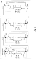
FIG. 2 is a schematic overview of a first battery system, in accordance with an embodiment of the present disclosure. In particular,FIG. 2 depicts thefirst battery system 200 that includes a plurality of battery packs 202 connected in series. Here, the battery packs 202 are similar to the battery packs 100 discussed inFIG. 1 . Not all of the details of the battery packs 202 are depicted in thebattery system 200 for clarity purposes. The battery packs depicted, here the battery packs 202-1, 202-2, 202-3, and 202-N, indicate any number of battery packs may be wired in series. Although at least fourbattery packs 202 are depicted in thebattery system 200, it should be realized that the various embodiments may be practiced with any number of battery packs 202. - In the
battery system 200, a negative end of the battery pack 202-1 is connected, via abattery pack connection 210, to the positive end of the battery pack 202-2. Thebattery pack connection 210 may be realized by an electrical cable, a busbar, or the like. This connection may be repeated for any number of battery packs 202. It is also contemplated that each of the battery packs 202 may have a different voltage across the plurality of lithium-ion battery cells 102 within therespective battery pack 202. - In one embodiment, the voltage potential across the lithium-
ion battery cells 102 of the battery pack 202-1 is 50 VDC, 25 VDC across both of the battery packs 202-2 and 202-3, and 15 VDC across the battery pack 202-N. In such an embodiment, a voltage measured across thebattery system 200 across all of the battery packs 202-1, 202-2, 202-3, and 202-N, with each having their respective disconnect mechanism 204 in itsoperational position 106 would be a total of 115 VDC. If in such an embodiment, thedisconnect mechanism 104 associated with the battery pack 202-2 were to be in thebypass position 108, the total voltage across thebattery system 200 would drop by 25 VDC to 90 VDC in part because the voltage potential provided by the plurality of lithium-ion battery cells 102 associated with the battery pack 202-2 would not be realized as it is removed from thebattery system 200 in place of the bus-power pass through 112. - The voltage of the
battery system 200 may be increased by the addition of more battery packs 202, an increased voltage of eachbattery pack 202, or a combination of both. In some embodiments, thebattery system 200 is configured to operate above 400 VDC. - As depicted in the
battery system 200, thedisconnect mechanism 104, the bus power pass through 112, and thecurrent sensors 116 are integral to the battery packs 202. In such a system, thebattery pack 202 acts as a stand-alone unit, with these sub-components being internal and integral to thebattery pack 202. Thus, troubleshooting and repair of thedisconnect mechanism 104, thecurrent sensor 116, or thecurrent sensors 116 may be realized by removing therespective battery pack 202 from thebattery system 200, replacing the out-of-specification (e.g. failed or non-functioning)battery pack 202 with a functioningbattery pack 202, and troubleshooting and/or repairing the out-of-specification components at a later time and location. Such a battery system would prevent the vehicle thebattery system 200 is installed in from being delayed during the troubleshooting and repairs of these out-of-specification components. -
FIG. 3 is a schematic overview of a second battery system, in accordance with an embodiment of the present disclosure. In particular,FIG. 3 depicts thebattery system 300 that is similar to thebattery system 200 ofFIG. 2 . However, as compared to thebattery system 200, thebattery pack connection 310 includes thedisconnect mechanism 304, the bus-power pass through 312, and thecurrent sensors 316 as integral components of thebattery pack connection 310 rather than thebattery pack 302. - Otherwise, the
battery system 300 may operate the same as thebattery system 200, with the battery packs 302-1, 302-2, 302-3 to 302-N being wired in series via thebattery pack connection 310. As compared to thebattery system 200, thebattery system 300 includes battery packs 302 that interact with thedisconnect mechanism 304, thecurrent sensors 316, and the bus-power pass through 312 outside of thebattery pack 302. - In such a system, in response to the
BMS 114 detecting a triggering event in the respective battery pack performance, theBMS 114 causes thedisconnect mechanism 304 to be in thebypass position 108 between thebattery pack connection 310 and the bus-power pass through 312. - As compared to the
battery system 200, thebattery system 300 allows for a simpler design of the battery packs 302 by allocating some of the components to thebattery pack connection 310. - While
FIGs. 2 and3 depict all three of the disconnect mechanism, the current sensor, and the bus-power pass through either being integral to the battery pack or the battery pack connection, it is contemplated that the battery system may include some of these components within the battery pack and the others within the battery pack connection. - Further, to increase redundancy, components may be duplicated. For example, a battery system may include both a
disconnect mechanism 104 integral to thebattery pack 202 and adisconnect mechanism 304 integral to thebattery pack connection 310. - The teachings of the present disclosure have wide uses throughout industry. In one non-limiting example, the
battery system 200 is utilized to operate, or power, an aircraft's propulsion system, which is discussed in more detail below in conjunction withFIG. 4 . -
FIG. 4 depicts a method, in accordance with an embodiment of the present disclosure. In particular,FIG. 4 depicts themethod 400 that includes operating a disconnect in an operational position atblock 402, monitoring battery cell current atblock 404, detecting a short circuit atblock 406, and causing the disconnect to operate in the bypass position atblock 408. - The
method 400 may be carried out by thebattery pack 100, thebattery system 200, thebattery system 300, or any similar system. - By way of example, the
battery system 200 will be used to more fully explain themethod 400. In such an example, thebattery system 200 includes twelvebattery packs 202 wired in series via thebattery pack connection 210, with eachbattery pack 202 having a voltage of 50 VDC across the respective plurality of lithium-ion battery cells 102. - At
block 402, each of the twelvebattery packs 202 are operating with thedisconnect mechanism 104 in theoperational position 106. This electrically connects thebattery pack connection 210 with the voltage from the respective plurality of lithium-ion battery cells 102 to form the battery bus voltage across thewhole battery system 200. Because eachbattery pack 202 is operating with itsdisconnect mechanism 104 in theoperational position 106, the total voltage across the battery bus is 600 VDC. This total voltage may be applied to an airplane's propulsion system, to other airplane services, or the like, via an electrical distribution system configured to provide the electrical power from the battery system to different electrical loads. - At
block 404, the battery current (e.g., the battery cell current) of the lithium-ion battery pack 202 is monitored via thecurrent sensor 116. TheBMS 114 receives current information and is configured to detect a short circuit condition. Additionally, or alternatively to monitoring battery cell current as depicted inFIG. 4 , theBMS 114 may monitor thebattery pack 202 for other indications of a thermal increase condition which may serve as a triggering event. Such indications may include detecting an overvoltage condition, an undervoltage condition, a temperature exceeding a threshold temperature value, a pressure exceeding a threshold pressure value, and the like. Thus, either the detection of a short circuit via thecurrent sensor 116 or the detection of a thermal increase condition may be a triggering event that causes theBMS 114 to cause thedisconnect mechanism 104 to operate in thebypass position 108. - At
block 406, theBMS 114 determines if a short circuit, or in some embodiments any other triggering event, has occurred. If a short circuit or triggering event has not been detected, thebattery system 200 continues to operate perblock 402, with therespective disconnect mechanisms 104 being in theoperational position 106. Atblock 408, if a short circuit or triggering event has been detected in arespective battery pack 202, therespective disconnect mechanism 104 is caused to operate in thebypass position 108. This connects thebattery pack connection 210 with the respective bus-power pass through 112 for therespective battery pack 202 in which the short circuit or triggering event was detected, effectively bypassing therespective battery pack 202. - In the example utilizing the
battery system 200, if a short circuit or triggering event is detected (block 406) in the battery pack 202-2, theBMS 114 in battery pack 202-2 causes, via thedisconnect mechanism control 118, thedisconnect mechanism 104 in battery pack 202-2 to operate in the bypass position 108 (block 408). The remainder of the battery packs 202 in thebattery system 200 continue to operate with theirrespective disconnect mechanisms 104 in theoperational position 106 as a result of the battery pack 202-2 detecting the short circuit or triggering event. Thus, the total voltage across thebattery system 200 drops by 50 VDC to a total of 550 VDC because one of the 50 VDC battery packs (i.e.; battery pack 202-2) has its plurality of lithium-ion battery cells 102 removed from providing power to thebattery bus 210 because itsdisconnect mechanism 104 is electrically connected to the bus-power pass through 112. - Because the
battery system 200 is now operating with one less battery pack, the power output (and thus its current) provided by each of the other battery packs 202 is expected to increase in order to maintain a constant power output. - The
BMS 114 of battery pack 202-2 may be configured to provide communication signals to a central processing unit and/or the other battery packs 202 within thebattery system 200 indicating that the battery pack 202-2 is operating with itsdisconnect mechanism 104 in thebypass position 108, and is thus not providing power to the battery bus. - The central processing unit may be configured to provide an indication to operators of the vehicle (e.g., the pilots of the airplane), transmit a message to a third party separate from the vehicle, or the like, indicating that the
battery system 200 has detected a triggering event and at least one of the battery packs 202 is operating with itsdisconnect mechanism 104 in thebypass position 108. The central processing system may further be configured to automatically reduce power consumption (e.g., by reducing propulsion power by a set fraction) to compensate for the reduction of available power from thebattery system 200. - Further, in response to receiving an indication that another
battery pack 202 is operating with itsdisconnect mechanism 104 in thebypass position 108, the threshold values for detecting a short circuit or thermal increase condition may be altered by the remaining battery packs 202 in thebattery system 200. For example, as an immediate response to onebattery pack 202 having itsdisconnect mechanism 104 being transitioned to thebypass position 108, it is expected that the current from the remaining battery packs 202 will increase. During the time period of this transient, as determined by asecond battery pack 202 receiving a notification that thefirst battery pack 202 has detected a triggering event in thefirst battery pack 202, the threshold limit for detecting a short circuit or a thermal increase condition within thesecond battery pack 202 may be increased to prevent an inadvertent detection of a triggering event or a short circuit as the current increases to meet the demand from thefirst battery pack 202 being removed from providing power to thebattery system 200. - In various embodiments, the transition of the
disconnect mechanism 104 from theoperational position 106 to thebypass position 108 is an instantaneous, or a near-instantaneous, transition. - The
battery system 200 may be used in another embodiment of the present disclosure. In such an embodiment, thebattery system 200 includes thirteen battery packs 202, each having a potential voltage of 50 VDC across the respective plurality of lithium-ion battery cells 102. At least one of the thirteen battery packs 202 is identified as a reserve battery pack. The reserve battery pack initially operates with itsbattery disconnect mechanism 104 in thebypass position 108. The remainder of the thirteen battery packs are identified as operating battery packs and have their respectivebattery disconnect mechanisms 104 in theoperational position 106. Thus, in an embodiment with one reserve battery pack and twelve operating battery packs, the total voltage across thebattery bus 210 is 600 VDC which is generated by the twelve 50 VDC operating battery packs. - During normal operations, each of the operational battery packs may perform the
method 400. Responsive to detecting a short circuit (block 406), a respective battery pack may cause its disconnect mechanism to operate in its bypass position (block 408). Additionally, the respective battery pack that detected the short circuit (or other triggering event) provides, or transmits, a communication signal to the remaining battery packs that it has detected a short circuit (e.g., via 120-124). Responsive to receiving the communication that one of the battery packs identified as an operational battery pack is now operating with its disconnect mechanism in the bypass position, the reserve battery pack transitions its disconnect mechanism from the bypass position to the operational position. As a result, when one of the operational battery packs is removed from applying a voltage to the battery bus (e.g., per the method 400), the reserve battery pack becomes an operational battery pack to make up for the energy no longer being supplied to the battery bus. - In another embodiment of a battery system having a reserve battery pack, the reserve battery pack may initially operate with its battery disconnect mechanism in the bypass position. However, under peak-load conditions of the vehicle the battery system is installed, the reserve battery pack may become an operational battery pack with its disconnect mechanism transitioned to the operational position for the duration of the peak load conditions. For example, during take-off of an airplane, the battery system may operate with all battery packs, including any reserve battery packs, having their disconnect mechanism in the operational positions. After the peak load condition has subsided (e.g., the airplane at cruising altitude), the battery system may return to having at least one battery pack operating as a reserve battery pack with its disconnect mechanism in the bypass position.
- Further, the disclosure comprises embodiments according to the following clauses:
-
Clause 1. A battery pack comprising: a plurality of lithium-ion battery cells; a disconnect mechanism operable in an operational position between a battery bus and the plurality of lithium-ion battery cells and a bypass position between the battery bus and a bus-power pass through; and a battery management system (BMS) configured to: monitor battery pack performance; and responsive to detecting a triggering event in the battery pack performance, cause the disconnect mechanism to be in the bypass position. - Clause 2. The battery pack of
clause 1, further comprising a current sensor configured to monitor the battery pack performance by monitoring a battery current from the plurality of lithium-ion battery cells. - Clause 3. The battery pack of
clause 1 or 2, wherein the triggering event comprises detecting a short circuit via the current sensor. - Clause 4. The battery pack of any of the preceding clauses, wherein the triggering event comprises detecting a thermal increase condition of the lithium-ion battery cells.
- Clause 5. The battery pack of any of the preceding clauses, wherein the thermal increase condition is detected by detecting at least one of an overvoltage condition, an undervoltage condition, and a temperature exceeding a temperature threshold value.
- Clause 6. The battery pack of any of the preceding clauses, wherein the disconnect mechanism is one of a single-pole double-throw switch and a solid state switch.
- Clause 7. The battery pack of any of the preceding clauses, further comprising a disconnect mechanism control operably connected to the disconnect mechanism, the disconnect mechanism control configured to: cause the disconnect mechanism to be in the operational position when energized; and cause the disconnect mechanism to be in the bypass position when deenergized.
- Clause 8. A battery system comprising: a plurality of battery packs electrically connected in series, a respective battery pack in the plurality of battery packs comprising a plurality of lithium-
ion battery cells 102; a battery pack connection configured to connect at least two of the battery packs in the plurality of battery packs in series; and at least one disconnect mechanism associated with the respective battery pack in the plurality of battery packs operable in an operational position between the battery pack connection and the plurality of lithium-ion battery cells of the respective battery pack and a bypass position between the battery bus and a bus-power pass through; and a battery management system (BMS) associated with the respective battery pack in the plurality of battery packs, the BMS configured to: monitor the respective battery pack performance; and responsive to detecting a triggering event in the respective battery pack performance, cause the at least one disconnect mechanism to be in the bypass position. - Clause 9. The battery system of clause 8, wherein the at least one disconnect mechanism and the bus-power pass through are integral to at least one of the respective battery pack and the battery pack connection.
- Clause 10. The battery system of clause 8 or 9, further comprising at least one disconnect mechanism control operably coupled to an associated one of the at least one disconnect mechanisms and responsive to the triggering event, the at least one disconnect mechanism control is configured to: cause the associated disconnect mechanism to be in the operational position when energized; and cause the associated disconnect mechanism to be in the bypass position when deenergized.
- Clause 11. The battery system of clause 8, 9 or 10, further comprising a current sensor configured to monitor performance of the respective battery pack in the plurality of battery packs at least in part by monitoring a battery current from the plurality of lithium-ion battery cells in the respective battery pack.
- Clause 12. The battery system of any of the clauses 8 to 11, wherein the triggering event comprises detecting a short circuit in the respective battery pack via the current sensor.
- Clause 13. The battery system of any of the clauses 8 to 12, wherein one of the at least one disconnect mechanisms is one of a single-pole double-throw switch and a solid state switch.
- Clause 14. The battery system of any of the clauses 8 to 13, wherein: at least one of the battery packs in the plurality of battery packs is identified as an operational battery pack initially having its associated disconnect mechanism in the operational position; at least one of the battery packs in the plurality of battery packs is identified as a reserve battery pack initially having its associated disconnect mechanism the bypass position; further in response to one of the operational battery packs detecting the triggering event, the operational battery pack transmits a communication signal to one of the reserve battery packs; and responsive to receiving the communication signal, the reserve battery pack causes its associated disconnect mechanism to transition from the bypass position to the operational position.
- Clause 15. The battery system of any of the clauses 8 to 14 configured to operate above 400 VDC.
- Clause 16. The battery system of any of the clauses 8 to 15 configured to operate a propulsion system on an airplane.
- Clause 17. A method of operating a lithium-ion battery pack wired in series with a plurality of other battery packs, the method comprising: operating a disconnect mechanism in an operational position, the operational position electrically connecting a battery pack connection with a plurality of battery cells within the lithium-ion battery pack; monitoring a battery current of the lithium-ion battery pack via a current sensor; and responsive to detecting a short circuit within the lithium-ion battery pack via the current sensor, causing the disconnect mechanism to operate in a bypass position, the bypass position electrically connecting the battery pack connection with a bus-power pass-through of the lithium-ion battery pack.
- Clause 18. The method of clause 17, wherein a transition between the operational position and the bypass position is an instantaneous transition.
- Clause 19. The method of clause 17 or 18, wherein the disconnect mechanism is one of a single-pole double-throw switch and a solid state switch.
- Clause 20. The method of clause 17, 18 or 19, further comprising transmitting, to a reserve battery pack having an associated disconnect mechanism in a bypass position, a communication signal indicating that the disconnect mechanism of the lithium-ion battery pack is in the bypass position, wherein the reserve battery pack is configured to transition the associated disconnect mechanism from the bypass position to the operational position responsive to receiving the communication signal.
- While the preceding text sets forth a detailed description of numerous different embodiments, it should be understood that the legal scope of protection is defined by the words of the claims set forth at the end of this patent. The detailed description is to be construed as exemplary only and does not describe every possible embodiment since describing every possible embodiment would be impractical, if not impossible. Numerous alternative embodiments could be implemented, using either current technology or technology developed after the filing date of this patent, which would still fall within the scope of the claims defining the scope of protection.
- It should also be understood that, unless a term was expressly defined herein, there is no intent to limit the meaning of that term, either expressly or by implication, beyond its plain or ordinary meaning, and such term should not be interpreted to be limited in scope based on any statement made in any section of this patent (other than the language of the claims). To the extent that any term recited in the claims at the end of this patent is referred to herein in a manner consistent with a single meaning, that is done for sake of clarity only so as to not confuse the reader, and it is not intended that such claim term be limited, by implication or otherwise, to that single meaning.
Claims (11)
- A battery pack (100) comprising:a plurality of lithium-ion battery cells (102);a disconnect mechanism (104) operable in an operational position (106) between a battery bus (110) and the plurality of lithium-ion battery cells and a bypass position (108) between the battery bus and a bus-power pass through (112); anda battery management system (BMS) (114) configured to:monitor battery pack performance; andresponsive to detecting a triggering event in the battery pack performance, cause the disconnect mechanism to be in the bypass position.
- The battery pack of claim 1, further comprising a current sensor (116) configured to monitor the battery pack performance by monitoring a battery current from the plurality of lithium-ion battery cells.
- The battery pack of claim 1 or 2, wherein the triggering event comprises detecting a short circuit via the current sensor.
- The battery pack of claim 1, 2 or 3, wherein the triggering event comprises detecting a thermal increase condition of the lithium-ion battery cells.
- The battery pack of claim 4, wherein the thermal increase condition is detected by detecting at least one of an overvoltage condition, an undervoltage condition, and a temperature exceeding a temperature threshold value.
- The battery pack of any of claims 1-5 wherein the disconnect mechanism is one of a single-pole double-throw switch and a solid state switch.
- The battery pack of any of claims 1 to 6, further comprising a disconnect mechanism control (118) operably connected to the disconnect mechanism, the disconnect mechanism control configured to:cause the disconnect mechanism to be in the operational position when energized; andcause the disconnect mechanism to be in the bypass position when deenergized.
- A method (400) of operating a lithium-ion battery pack wired in series with a plurality of other battery packs, the method comprising:operating a disconnect mechanism in an operational position (402), the operational position electrically connecting a battery pack connection with a plurality of battery cells within the lithium-ion battery pack;monitoring a battery current of the lithium-ion battery pack via a current sensor (404); andresponsive to detecting a short circuit within the lithium-ion battery pack via the current sensor (406), causing the disconnect mechanism to operate in a bypass position (408), the bypass position electrically connecting the battery pack connection with a bus-power pass-through of the lithium-ion battery pack.
- The method of claim 8, wherein a transition between the operational position and the bypass position is an instantaneous transition.
- The method of claim 8 or 9, wherein the disconnect mechanism is one of a single-pole double-throw switch and a solid state switch.
- The method of claim 8, 9 or 10, further comprising transmitting, to a reserve battery pack having an associated disconnect mechanism in a bypass position, a communication signal indicating that the disconnect mechanism of the lithium-ion battery pack is in the bypass position, wherein the reserve battery pack is configured to transition the associated disconnect mechanism from the bypass position to the operational position responsive to receiving the communication signal.
Applications Claiming Priority (1)
| Application Number | Priority Date | Filing Date | Title |
|---|---|---|---|
| US16/047,931 US11621441B2 (en) | 2018-07-27 | 2018-07-27 | Li-Ion battery high voltage distribution system architecture |
Publications (2)
| Publication Number | Publication Date |
|---|---|
| EP3599653A1 true EP3599653A1 (en) | 2020-01-29 |
| EP3599653B1 EP3599653B1 (en) | 2022-01-05 |
Family
ID=66655271
Family Applications (1)
| Application Number | Title | Priority Date | Filing Date |
|---|---|---|---|
| EP19176809.2A Active EP3599653B1 (en) | 2018-07-27 | 2019-05-27 | Li-ion battery high voltage distribution system architecture |
Country Status (5)
| Country | Link |
|---|---|
| US (2) | US11621441B2 (en) |
| EP (1) | EP3599653B1 (en) |
| JP (1) | JP7432995B2 (en) |
| CN (1) | CN110783973B (en) |
| CA (1) | CA3044454C (en) |
Cited By (3)
| Publication number | Priority date | Publication date | Assignee | Title |
|---|---|---|---|---|
| EP3944456A1 (en) * | 2020-07-23 | 2022-01-26 | Aurora Flight Sciences Corporation, a subsidiary of The Boeing Company | Switchable battery management system |
| US11258279B1 (en) * | 2020-10-08 | 2022-02-22 | Element Energy, Inc. | Safe battery energy management systems, battery management system nodes, and methods |
| AT526056B1 (en) * | 2022-09-30 | 2023-11-15 | Avl List Gmbh | Modular storage device and method for equipping the same |
Families Citing this family (24)
| Publication number | Priority date | Publication date | Assignee | Title |
|---|---|---|---|---|
| US20210249981A1 (en) | 2018-09-05 | 2021-08-12 | Dpm Technologies Inc. | Systems and methods for intelligent control of rotating electric machines |
| JP7096193B2 (en) * | 2019-04-04 | 2022-07-05 | 矢崎総業株式会社 | Battery control unit and battery system |
| US11722026B2 (en) | 2019-04-23 | 2023-08-08 | Dpm Technologies Inc. | Fault tolerant rotating electric machine |
| JP7208177B2 (en) * | 2020-01-24 | 2023-01-18 | 株式会社藤商事 | game machine |
| JP7208178B2 (en) * | 2020-01-24 | 2023-01-18 | 株式会社藤商事 | game machine |
| KR102901907B1 (en) * | 2020-05-13 | 2025-12-19 | 주식회사 엘지에너지솔루션 | Battery pack containing fire suppression means |
| KR102798716B1 (en) * | 2020-05-22 | 2025-04-18 | 주식회사 엘지에너지솔루션 | Battery Pack, and Battery Rack Comprising the Same, and Energy Storage System |
| FR3112900B1 (en) | 2020-07-27 | 2022-07-29 | Limatech | Serial modular block (B l M o S e ) |
| US11916211B2 (en) | 2020-09-28 | 2024-02-27 | Hamilton Sundstrand Corporation | Extinguishing battery thermal runaway |
| US11936014B2 (en) | 2020-09-28 | 2024-03-19 | Hamilton Sundstrand Corporation | Battery cell with sensors |
| US11936007B2 (en) | 2020-09-28 | 2024-03-19 | Hamilton Sundstrand Corporation | Battery system with optical connections |
| US11804630B2 (en) | 2020-09-28 | 2023-10-31 | Hamilton Sundstrand Corporation (HSC) | Battery system with thermal control loop |
| US12556009B2 (en) * | 2021-01-19 | 2026-02-17 | The Boeing Company | Reconfigurable battery system for efficient charging and discharging |
| US20220309210A1 (en) * | 2021-03-24 | 2022-09-29 | The Boeing Company | Systems and methods for multi-conditional battery configuration |
| US11897362B2 (en) * | 2021-05-04 | 2024-02-13 | Exro Technologies Inc. | Systems and methods for individual control of a plurality of controllable units of battery cells |
| CN117337545A (en) | 2021-05-13 | 2024-01-02 | Exro技术公司 | Method and device for driving coils of polyphase motors |
| US11942658B2 (en) | 2021-06-28 | 2024-03-26 | Rivian Ip Holdings, Llc | Systems and methods for servicing high voltage components of a battery system |
| US12119509B2 (en) | 2021-06-28 | 2024-10-15 | Rivian Ip Holdings, Llc | Fasteners and assemblies for servicing high voltage components of a battery system |
| KR20240046176A (en) | 2021-07-08 | 2024-04-08 | 엑스로 테크놀로지스 아이엔씨. | Dynamically reconfigurable power converter using windings of an electric machine |
| US11685266B2 (en) * | 2021-09-01 | 2023-06-27 | GM Global Technology Operations LLC | Battery electric system having switchable architecture with thermal runaway protection |
| KR20230050562A (en) * | 2021-10-08 | 2023-04-17 | 현대자동차주식회사 | Apparatus for protecting of battery pack |
| CN114784435B (en) * | 2022-04-22 | 2024-02-13 | 湖南欧赛派克储能科技有限公司 | Energy storage battery system architecture |
| US11664670B1 (en) | 2022-08-21 | 2023-05-30 | Element Energy, Inc. | Methods and systems for updating state of charge estimates of individual cells in battery packs |
| US12119700B2 (en) * | 2023-01-20 | 2024-10-15 | Element Energy, Inc. | Systems and methods for adaptive electrochemical cell management |
Citations (2)
| Publication number | Priority date | Publication date | Assignee | Title |
|---|---|---|---|---|
| US20120319658A1 (en) * | 2011-06-17 | 2012-12-20 | Southwest Electronic Energy Group | Module bypass switch with bypass current monitoring |
| CN104362688A (en) * | 2014-10-27 | 2015-02-18 | 合肥创源车辆控制技术有限公司 | Battery pack redundancy connection method |
Family Cites Families (9)
| Publication number | Priority date | Publication date | Assignee | Title |
|---|---|---|---|---|
| US5710504A (en) * | 1996-05-20 | 1998-01-20 | The Board Of Trustees Of The University Of Illinois | Switched capacitor system for automatic battery equalization |
| JP5230789B2 (en) * | 2011-11-25 | 2013-07-10 | 三菱重工業株式会社 | Battery system |
| US9991723B2 (en) | 2012-09-17 | 2018-06-05 | The Boeing Company | Virtual cell method for battery management |
| US9484604B2 (en) * | 2013-02-25 | 2016-11-01 | The Boeing Company | Battery module system |
| US9287726B2 (en) | 2013-11-06 | 2016-03-15 | The Boeing Company | Virtual cell for battery thermal management |
| JP6277057B2 (en) * | 2014-05-13 | 2018-02-07 | デクセリアルズ株式会社 | Battery pack, battery system, and discharging method |
| US10629963B2 (en) * | 2015-12-24 | 2020-04-21 | Intel Corporation | Battery cell having a detection interface |
| GB2559793B (en) * | 2017-02-20 | 2020-07-08 | Ge Aviat Systems Ltd | Battery pack with reduced voltage variance |
| EP3401150B1 (en) * | 2017-05-04 | 2022-04-06 | Volvo Car Corporation | Dual voltage unit for a vehicle |
-
2018
- 2018-07-27 US US16/047,931 patent/US11621441B2/en active Active
-
2019
- 2019-05-15 JP JP2019092127A patent/JP7432995B2/en active Active
- 2019-05-27 EP EP19176809.2A patent/EP3599653B1/en active Active
- 2019-05-28 CA CA3044454A patent/CA3044454C/en active Active
- 2019-06-10 CN CN201910496077.5A patent/CN110783973B/en active Active
-
2023
- 2023-03-10 US US18/182,214 patent/US20230223606A1/en active Pending
Patent Citations (2)
| Publication number | Priority date | Publication date | Assignee | Title |
|---|---|---|---|---|
| US20120319658A1 (en) * | 2011-06-17 | 2012-12-20 | Southwest Electronic Energy Group | Module bypass switch with bypass current monitoring |
| CN104362688A (en) * | 2014-10-27 | 2015-02-18 | 合肥创源车辆控制技术有限公司 | Battery pack redundancy connection method |
Non-Patent Citations (1)
| Title |
|---|
| FEDERICO BARONTI ET AL: "Design of a module switch for battery pack reconfiguration in high-power applications", 28 May 2012 (2012-05-28), pages 1330 - 1335, XP032199905, ISBN: 978-1-4673-0159-6, Retrieved from the Internet <URL:https://ieeexplore.ieee.org/document/6237283> [retrieved on 20120712], DOI: 10.1109/ISIE.2012.6237283 * |
Cited By (4)
| Publication number | Priority date | Publication date | Assignee | Title |
|---|---|---|---|---|
| EP3944456A1 (en) * | 2020-07-23 | 2022-01-26 | Aurora Flight Sciences Corporation, a subsidiary of The Boeing Company | Switchable battery management system |
| US11258279B1 (en) * | 2020-10-08 | 2022-02-22 | Element Energy, Inc. | Safe battery energy management systems, battery management system nodes, and methods |
| AT526056B1 (en) * | 2022-09-30 | 2023-11-15 | Avl List Gmbh | Modular storage device and method for equipping the same |
| AT526056A4 (en) * | 2022-09-30 | 2023-11-15 | Avl List Gmbh | Modular storage device and method for equipping the same |
Also Published As
| Publication number | Publication date |
|---|---|
| CN110783973A (en) | 2020-02-11 |
| JP7432995B2 (en) | 2024-02-19 |
| JP2020017517A (en) | 2020-01-30 |
| US11621441B2 (en) | 2023-04-04 |
| CN110783973B (en) | 2025-05-09 |
| CA3044454A1 (en) | 2020-01-27 |
| CA3044454C (en) | 2024-04-23 |
| US20200036047A1 (en) | 2020-01-30 |
| EP3599653B1 (en) | 2022-01-05 |
| US20230223606A1 (en) | 2023-07-13 |
Similar Documents
| Publication | Publication Date | Title |
|---|---|---|
| US20230223606A1 (en) | Li-Ion Battery High Voltage Distribution System Architecture | |
| EP4044394B1 (en) | Systems and methods for fail-safe battery protection independent from battery management system | |
| US10464507B2 (en) | Battery management system and switching method thereof | |
| US8471529B2 (en) | Battery fault tolerant architecture for cell failure modes parallel bypass circuit | |
| EP2171824B1 (en) | Method of deactivating faulty battery cells | |
| US9478996B2 (en) | Battery cell unit comprising a battery cell and a monitoring and actuation unit for monitoring the battery cell and method for monitoring a battery cell | |
| US20220355679A1 (en) | High voltage electrical system for battery electric vehicle | |
| US9529053B2 (en) | Battery management system and method for determining the charge state battery cells, battery and motor vehicle comprising a battery management system | |
| US10490865B2 (en) | Abnormality determination apparatus | |
| CN104838536B (en) | battery management system and battery system | |
| US20200212507A1 (en) | Electricity storage system and management device | |
| US20140339892A1 (en) | Disconnection unit for disconnecting a battery from a power system and a motor vehicle having a lithium-ion battery | |
| EP4393777A1 (en) | Power supply system for vehicle | |
| CN114726083B (en) | Autonomous driving power distribution and power management system | |
| US20220250478A1 (en) | Method for operating an electric energy store, electric energy store, and device | |
| CN111585337A (en) | Power supply system and work vehicle | |
| CN104025369A (en) | Battery system and motor vehicle | |
| US9941714B2 (en) | Battery system and motor vehicle with battery system | |
| CN104052097B (en) | Battery module and the method being used for monitoring battery module | |
| CN106688156B (en) | Vehicle battery system | |
| CN111095719A (en) | battery device | |
| CN120150286A (en) | An electric aircraft power battery management system with fault isolation function | |
| US9985321B2 (en) | Battery system | |
| CN119133659A (en) | Marine energy storage system and discharge method thereof | |
| CN217882945U (en) | Distributed power supply device and vehicle |
Legal Events
| Date | Code | Title | Description |
|---|---|---|---|
| PUAI | Public reference made under article 153(3) epc to a published international application that has entered the european phase |
Free format text: ORIGINAL CODE: 0009012 |
|
| STAA | Information on the status of an ep patent application or granted ep patent |
Free format text: STATUS: REQUEST FOR EXAMINATION WAS MADE |
|
| 17P | Request for examination filed |
Effective date: 20190527 |
|
| AK | Designated contracting states |
Kind code of ref document: A1 Designated state(s): AL AT BE BG CH CY CZ DE DK EE ES FI FR GB GR HR HU IE IS IT LI LT LU LV MC MK MT NL NO PL PT RO RS SE SI SK SM TR |
|
| AX | Request for extension of the european patent |
Extension state: BA ME |
|
| REG | Reference to a national code |
Ref country code: DE Ref legal event code: R079 Ref document number: 602019010577 Country of ref document: DE Free format text: PREVIOUS MAIN CLASS: H01M0002340000 Ipc: H01M0010052500 |
|
| GRAP | Despatch of communication of intention to grant a patent |
Free format text: ORIGINAL CODE: EPIDOSNIGR1 |
|
| STAA | Information on the status of an ep patent application or granted ep patent |
Free format text: STATUS: GRANT OF PATENT IS INTENDED |
|
| RIC1 | Information provided on ipc code assigned before grant |
Ipc: H01M 50/572 20210101ALI20210802BHEP Ipc: H01M 50/20 20210101ALI20210802BHEP Ipc: H01M 10/48 20060101ALI20210802BHEP Ipc: H01M 10/42 20060101ALI20210802BHEP Ipc: H01M 10/0525 20100101AFI20210802BHEP |
|
| INTG | Intention to grant announced |
Effective date: 20210818 |
|
| GRAS | Grant fee paid |
Free format text: ORIGINAL CODE: EPIDOSNIGR3 |
|
| GRAA | (expected) grant |
Free format text: ORIGINAL CODE: 0009210 |
|
| STAA | Information on the status of an ep patent application or granted ep patent |
Free format text: STATUS: THE PATENT HAS BEEN GRANTED |
|
| AK | Designated contracting states |
Kind code of ref document: B1 Designated state(s): AL AT BE BG CH CY CZ DE DK EE ES FI FR GB GR HR HU IE IS IT LI LT LU LV MC MK MT NL NO PL PT RO RS SE SI SK SM TR |
|
| REG | Reference to a national code |
Ref country code: GB Ref legal event code: FG4D |
|
| REG | Reference to a national code |
Ref country code: CH Ref legal event code: EP |
|
| REG | Reference to a national code |
Ref country code: AT Ref legal event code: REF Ref document number: 1461381 Country of ref document: AT Kind code of ref document: T Effective date: 20220115 |
|
| REG | Reference to a national code |
Ref country code: DE Ref legal event code: R096 Ref document number: 602019010577 Country of ref document: DE |
|
| REG | Reference to a national code |
Ref country code: IE Ref legal event code: FG4D |
|
| REG | Reference to a national code |
Ref country code: LT Ref legal event code: MG9D |
|
| REG | Reference to a national code |
Ref country code: NL Ref legal event code: MP Effective date: 20220105 |
|
| REG | Reference to a national code |
Ref country code: AT Ref legal event code: MK05 Ref document number: 1461381 Country of ref document: AT Kind code of ref document: T Effective date: 20220105 |
|
| PG25 | Lapsed in a contracting state [announced via postgrant information from national office to epo] |
Ref country code: NL Free format text: LAPSE BECAUSE OF FAILURE TO SUBMIT A TRANSLATION OF THE DESCRIPTION OR TO PAY THE FEE WITHIN THE PRESCRIBED TIME-LIMIT Effective date: 20220105 |
|
| PG25 | Lapsed in a contracting state [announced via postgrant information from national office to epo] |
Ref country code: SE Free format text: LAPSE BECAUSE OF FAILURE TO SUBMIT A TRANSLATION OF THE DESCRIPTION OR TO PAY THE FEE WITHIN THE PRESCRIBED TIME-LIMIT Effective date: 20220105 Ref country code: RS Free format text: LAPSE BECAUSE OF FAILURE TO SUBMIT A TRANSLATION OF THE DESCRIPTION OR TO PAY THE FEE WITHIN THE PRESCRIBED TIME-LIMIT Effective date: 20220105 Ref country code: PT Free format text: LAPSE BECAUSE OF FAILURE TO SUBMIT A TRANSLATION OF THE DESCRIPTION OR TO PAY THE FEE WITHIN THE PRESCRIBED TIME-LIMIT Effective date: 20220505 Ref country code: NO Free format text: LAPSE BECAUSE OF FAILURE TO SUBMIT A TRANSLATION OF THE DESCRIPTION OR TO PAY THE FEE WITHIN THE PRESCRIBED TIME-LIMIT Effective date: 20220405 Ref country code: LT Free format text: LAPSE BECAUSE OF FAILURE TO SUBMIT A TRANSLATION OF THE DESCRIPTION OR TO PAY THE FEE WITHIN THE PRESCRIBED TIME-LIMIT Effective date: 20220105 Ref country code: HR Free format text: LAPSE BECAUSE OF FAILURE TO SUBMIT A TRANSLATION OF THE DESCRIPTION OR TO PAY THE FEE WITHIN THE PRESCRIBED TIME-LIMIT Effective date: 20220105 Ref country code: ES Free format text: LAPSE BECAUSE OF FAILURE TO SUBMIT A TRANSLATION OF THE DESCRIPTION OR TO PAY THE FEE WITHIN THE PRESCRIBED TIME-LIMIT Effective date: 20220105 Ref country code: BG Free format text: LAPSE BECAUSE OF FAILURE TO SUBMIT A TRANSLATION OF THE DESCRIPTION OR TO PAY THE FEE WITHIN THE PRESCRIBED TIME-LIMIT Effective date: 20220405 |
|
| PG25 | Lapsed in a contracting state [announced via postgrant information from national office to epo] |
Ref country code: PL Free format text: LAPSE BECAUSE OF FAILURE TO SUBMIT A TRANSLATION OF THE DESCRIPTION OR TO PAY THE FEE WITHIN THE PRESCRIBED TIME-LIMIT Effective date: 20220105 Ref country code: LV Free format text: LAPSE BECAUSE OF FAILURE TO SUBMIT A TRANSLATION OF THE DESCRIPTION OR TO PAY THE FEE WITHIN THE PRESCRIBED TIME-LIMIT Effective date: 20220105 Ref country code: GR Free format text: LAPSE BECAUSE OF FAILURE TO SUBMIT A TRANSLATION OF THE DESCRIPTION OR TO PAY THE FEE WITHIN THE PRESCRIBED TIME-LIMIT Effective date: 20220406 Ref country code: FI Free format text: LAPSE BECAUSE OF FAILURE TO SUBMIT A TRANSLATION OF THE DESCRIPTION OR TO PAY THE FEE WITHIN THE PRESCRIBED TIME-LIMIT Effective date: 20220105 Ref country code: AT Free format text: LAPSE BECAUSE OF FAILURE TO SUBMIT A TRANSLATION OF THE DESCRIPTION OR TO PAY THE FEE WITHIN THE PRESCRIBED TIME-LIMIT Effective date: 20220105 |
|
| PG25 | Lapsed in a contracting state [announced via postgrant information from national office to epo] |
Ref country code: IS Free format text: LAPSE BECAUSE OF FAILURE TO SUBMIT A TRANSLATION OF THE DESCRIPTION OR TO PAY THE FEE WITHIN THE PRESCRIBED TIME-LIMIT Effective date: 20220505 |
|
| REG | Reference to a national code |
Ref country code: DE Ref legal event code: R097 Ref document number: 602019010577 Country of ref document: DE |
|
| PG25 | Lapsed in a contracting state [announced via postgrant information from national office to epo] |
Ref country code: SM Free format text: LAPSE BECAUSE OF FAILURE TO SUBMIT A TRANSLATION OF THE DESCRIPTION OR TO PAY THE FEE WITHIN THE PRESCRIBED TIME-LIMIT Effective date: 20220105 Ref country code: SK Free format text: LAPSE BECAUSE OF FAILURE TO SUBMIT A TRANSLATION OF THE DESCRIPTION OR TO PAY THE FEE WITHIN THE PRESCRIBED TIME-LIMIT Effective date: 20220105 Ref country code: RO Free format text: LAPSE BECAUSE OF FAILURE TO SUBMIT A TRANSLATION OF THE DESCRIPTION OR TO PAY THE FEE WITHIN THE PRESCRIBED TIME-LIMIT Effective date: 20220105 Ref country code: EE Free format text: LAPSE BECAUSE OF FAILURE TO SUBMIT A TRANSLATION OF THE DESCRIPTION OR TO PAY THE FEE WITHIN THE PRESCRIBED TIME-LIMIT Effective date: 20220105 Ref country code: DK Free format text: LAPSE BECAUSE OF FAILURE TO SUBMIT A TRANSLATION OF THE DESCRIPTION OR TO PAY THE FEE WITHIN THE PRESCRIBED TIME-LIMIT Effective date: 20220105 Ref country code: CZ Free format text: LAPSE BECAUSE OF FAILURE TO SUBMIT A TRANSLATION OF THE DESCRIPTION OR TO PAY THE FEE WITHIN THE PRESCRIBED TIME-LIMIT Effective date: 20220105 |
|
| PLBE | No opposition filed within time limit |
Free format text: ORIGINAL CODE: 0009261 |
|
| STAA | Information on the status of an ep patent application or granted ep patent |
Free format text: STATUS: NO OPPOSITION FILED WITHIN TIME LIMIT |
|
| PG25 | Lapsed in a contracting state [announced via postgrant information from national office to epo] |
Ref country code: AL Free format text: LAPSE BECAUSE OF FAILURE TO SUBMIT A TRANSLATION OF THE DESCRIPTION OR TO PAY THE FEE WITHIN THE PRESCRIBED TIME-LIMIT Effective date: 20220105 |
|
| 26N | No opposition filed |
Effective date: 20221006 |
|
| REG | Reference to a national code |
Ref country code: CH Ref legal event code: PL |
|
| REG | Reference to a national code |
Ref country code: BE Ref legal event code: MM Effective date: 20220531 |
|
| PG25 | Lapsed in a contracting state [announced via postgrant information from national office to epo] |
Ref country code: MC Free format text: LAPSE BECAUSE OF FAILURE TO SUBMIT A TRANSLATION OF THE DESCRIPTION OR TO PAY THE FEE WITHIN THE PRESCRIBED TIME-LIMIT Effective date: 20220105 Ref country code: LU Free format text: LAPSE BECAUSE OF NON-PAYMENT OF DUE FEES Effective date: 20220527 Ref country code: LI Free format text: LAPSE BECAUSE OF NON-PAYMENT OF DUE FEES Effective date: 20220531 Ref country code: CH Free format text: LAPSE BECAUSE OF NON-PAYMENT OF DUE FEES Effective date: 20220531 |
|
| PG25 | Lapsed in a contracting state [announced via postgrant information from national office to epo] |
Ref country code: SI Free format text: LAPSE BECAUSE OF FAILURE TO SUBMIT A TRANSLATION OF THE DESCRIPTION OR TO PAY THE FEE WITHIN THE PRESCRIBED TIME-LIMIT Effective date: 20220105 |
|
| PG25 | Lapsed in a contracting state [announced via postgrant information from national office to epo] |
Ref country code: IE Free format text: LAPSE BECAUSE OF NON-PAYMENT OF DUE FEES Effective date: 20220527 |
|
| PG25 | Lapsed in a contracting state [announced via postgrant information from national office to epo] |
Ref country code: BE Free format text: LAPSE BECAUSE OF NON-PAYMENT OF DUE FEES Effective date: 20220531 |
|
| P01 | Opt-out of the competence of the unified patent court (upc) registered |
Effective date: 20230516 |
|
| PG25 | Lapsed in a contracting state [announced via postgrant information from national office to epo] |
Ref country code: IT Free format text: LAPSE BECAUSE OF FAILURE TO SUBMIT A TRANSLATION OF THE DESCRIPTION OR TO PAY THE FEE WITHIN THE PRESCRIBED TIME-LIMIT Effective date: 20220105 |
|
| PG25 | Lapsed in a contracting state [announced via postgrant information from national office to epo] |
Ref country code: MK Free format text: LAPSE BECAUSE OF FAILURE TO SUBMIT A TRANSLATION OF THE DESCRIPTION OR TO PAY THE FEE WITHIN THE PRESCRIBED TIME-LIMIT Effective date: 20220105 Ref country code: CY Free format text: LAPSE BECAUSE OF FAILURE TO SUBMIT A TRANSLATION OF THE DESCRIPTION OR TO PAY THE FEE WITHIN THE PRESCRIBED TIME-LIMIT Effective date: 20220105 |
|
| PG25 | Lapsed in a contracting state [announced via postgrant information from national office to epo] |
Ref country code: HU Free format text: LAPSE BECAUSE OF FAILURE TO SUBMIT A TRANSLATION OF THE DESCRIPTION OR TO PAY THE FEE WITHIN THE PRESCRIBED TIME-LIMIT; INVALID AB INITIO Effective date: 20190527 |
|
| PG25 | Lapsed in a contracting state [announced via postgrant information from national office to epo] |
Ref country code: TR Free format text: LAPSE BECAUSE OF FAILURE TO SUBMIT A TRANSLATION OF THE DESCRIPTION OR TO PAY THE FEE WITHIN THE PRESCRIBED TIME-LIMIT Effective date: 20220105 |
|
| PG25 | Lapsed in a contracting state [announced via postgrant information from national office to epo] |
Ref country code: MT Free format text: LAPSE BECAUSE OF FAILURE TO SUBMIT A TRANSLATION OF THE DESCRIPTION OR TO PAY THE FEE WITHIN THE PRESCRIBED TIME-LIMIT Effective date: 20220105 |
|
| PGFP | Annual fee paid to national office [announced via postgrant information from national office to epo] |
Ref country code: DE Payment date: 20250529 Year of fee payment: 7 |
|
| PGFP | Annual fee paid to national office [announced via postgrant information from national office to epo] |
Ref country code: GB Payment date: 20250527 Year of fee payment: 7 |
|
| PGFP | Annual fee paid to national office [announced via postgrant information from national office to epo] |
Ref country code: FR Payment date: 20250526 Year of fee payment: 7 |