EP3599463A1 - Method for adapting the concentration of sample gas in a gas mixture to be analysed by a gas chromatograph assembly, and chromatograph assembly therefore - Google Patents
Method for adapting the concentration of sample gas in a gas mixture to be analysed by a gas chromatograph assembly, and chromatograph assembly therefore Download PDFInfo
- Publication number
- EP3599463A1 EP3599463A1 EP18185795.4A EP18185795A EP3599463A1 EP 3599463 A1 EP3599463 A1 EP 3599463A1 EP 18185795 A EP18185795 A EP 18185795A EP 3599463 A1 EP3599463 A1 EP 3599463A1
- Authority
- EP
- European Patent Office
- Prior art keywords
- gas
- chromatograph
- sample
- inlet
- gas chromatograph
- Prior art date
- Legal status (The legal status is an assumption and is not a legal conclusion. Google has not performed a legal analysis and makes no representation as to the accuracy of the status listed.)
- Granted
Links
Images

Classifications
-
- G—PHYSICS
- G01—MEASURING; TESTING
- G01N—INVESTIGATING OR ANALYSING MATERIALS BY DETERMINING THEIR CHEMICAL OR PHYSICAL PROPERTIES
- G01N30/00—Investigating or analysing materials by separation into components using adsorption, absorption or similar phenomena or using ion-exchange, e.g. chromatography or field flow fractionation
- G01N30/02—Column chromatography
- G01N30/04—Preparation or injection of sample to be analysed
- G01N30/06—Preparation
-
- G—PHYSICS
- G01—MEASURING; TESTING
- G01N—INVESTIGATING OR ANALYSING MATERIALS BY DETERMINING THEIR CHEMICAL OR PHYSICAL PROPERTIES
- G01N30/00—Investigating or analysing materials by separation into components using adsorption, absorption or similar phenomena or using ion-exchange, e.g. chromatography or field flow fractionation
- G01N30/02—Column chromatography
- G01N30/88—Integrated analysis systems specially adapted therefor, not covered by a single one of the groups G01N30/04 - G01N30/86
-
- G—PHYSICS
- G01—MEASURING; TESTING
- G01N—INVESTIGATING OR ANALYSING MATERIALS BY DETERMINING THEIR CHEMICAL OR PHYSICAL PROPERTIES
- G01N30/00—Investigating or analysing materials by separation into components using adsorption, absorption or similar phenomena or using ion-exchange, e.g. chromatography or field flow fractionation
- G01N30/02—Column chromatography
- G01N30/88—Integrated analysis systems specially adapted therefor, not covered by a single one of the groups G01N30/04 - G01N30/86
- G01N2030/8809—Integrated analysis systems specially adapted therefor, not covered by a single one of the groups G01N30/04 - G01N30/86 analysis specially adapted for the sample
- G01N2030/884—Integrated analysis systems specially adapted therefor, not covered by a single one of the groups G01N30/04 - G01N30/86 analysis specially adapted for the sample organic compounds
- G01N2030/8854—Integrated analysis systems specially adapted therefor, not covered by a single one of the groups G01N30/04 - G01N30/86 analysis specially adapted for the sample organic compounds involving hydrocarbons
Definitions
- the invention concerns a method for adapting the concentration of a sample gas in a gas mixture to be analysed by a gas chromatograph assembly, as well as a gas chromatograph assembly for adapting the concentration of a sample gas to be analysed.
- Gas chromatography is employed to separate gas components from a gas mixture and to detect these separated gas components. This is achieved by injecting small amounts of the gas mixture into a tube shaped column.
- the column is typically either a narrow capillary tube, the inner surface of which is provided with a surface active coating or a slightly larger tube filled with a surface active powder, which in both cases is called the "stationary phase".
- a carrier gas such as hydrogen, helium or air is employed to carry the amount of the gas mixture to be analysed through the column.
- the carrier gas is usually referred to as the "mobile phase.”
- the gas mixture to be analysed follows the mobile phase through the stationary phase, thereby pushing the gas mixture slowly through the stationary phase.
- Gas chromatography is used in the forensic science, medicine and environmental protection fields.
- Gas chromatography is also used in the field of gas leak detection, particularly for assessing whether a certain gas component measured on the ground surface originates from a leak in an underground pipeline carrying a natural gas.
- the main component of the natural gas and of gas from biological decay processes (“swamp gas”) is methane. Swamp gas is produced when microorganisms digest biological waste. Before repair work for repairing a leak in a buried underground pipeline is initiated, it needs to be ensured that the gas detected at the ground surface does not originate from a swamp gas emission.
- the concentration of sample gas in the gas sample analysed by the gas chromatograph is critical. On the one hand, the concentration needs to be high enough in order to achieve a sufficient measurement signal. On the other hand, the concentration must not exceed a certain value, in order to avoid overloading of the stationary phase within the gas chromatograph column. Overloading creates distorted peaks in the measurement signal and can lead to misinterpretation of the gas type, or can even result in covering or hiding peaks of several gas components. This is particularly critical for a simple column without any temperature control.
- the object of the invention is to provide a method for adapting the concentration of a sample gas in a gas mixture to be analysed by a gas chromatograph assembly.
- a gas chromatograph assembly for adapting the concentration of a sample gas in a gas mixture to be analysed shall also be provided.
- the gas chromatograph assembly of the invention comprises a sample gas inlet for introducing a sample gas to be analysed, a secondary gas inlet, as well as a gas chromatograph sensor, a gas chromatograph column, and a gas chromatograph bypass parallel to the column.
- a gas mixture is created from the sample gas which enters through the sample gas inlet, and from the secondary gas which enters through the secondary gas inlet.
- the gas mixture is conducted via the gas chromatograph bypass, such that the gas mixture can actually flow within the gas chromatograph assembly without being blocked by the column.
- the gas chromatograph bypass facilitates the mixing of the two gas components.
- the invention achieves a gradual reduction of the concentration of sample gas within the gas mixture by repeating the introduction of the secondary gas and the mixing of the newly introduced secondary gas with the gas mixture already present within the gas chromatograph assembly without further introducing sample gas.
- the reduction of the sample gas concentration is performed until the concentration of sample gas within the gas mixture reaches a desired predetermined level, at which a sufficient measurement signal from the gas chromatograph sensor is generated without overloading of the stationary phase in the column.
- the sample gas concentration is preferably measured during or before step d), i.e. before the introduction of sample gas or secondary gas is repeated, in order to determine whether the sample gas concentration has already reached the predetermined level.
- This measurement can be made with a secondary sensor assembly, such as an infrared sensor assembly.
- the sample gas introduced during step a) can be conducted through the secondary sensor assembly to the gas chromatograph sensor.
- step d) the repeating according to step d) is performed a predetermined number of times without measuring the sample gas concentration.
- the gas chromatograph assembly comprises a gas conducting loop comprising the gas chromatograph bypass and the gas chromatograph sensor, in order to achieve mixing of the sample gas and the secondary gas during circulation through the loop.
- the loop also comprises the secondary sensor assembly, the sample gas concentration can be measured at every cycle, or even continuously, in order to be able to measure and control the gradual increase or decrease of the sample gas concentration.
- the loop may comprise a gas modulation valve being adapted to alternatingly connect either of the sample gas inlet and the secondary gas inlet with the loop.
- the secondary gas inlet can be a reference gas inlet which is usually employed to compare the gas sample with a reference gas.
- the gas modulation valve may connect the sample gas inlet with the loop during step a) while separating the secondary/reference gas inlet from the loop.
- the gas modulation valve connects the secondary gas inlet with the loop while separating the sample gas inlet from the loop.
- the gas modulation valve connects the sample gas inlet and the secondary/reference gas inlet with the secondary sensor assembly, typically an infrared sensor assembly.
- the secondary sensor assembly comprises a secondary sensor assembly inlet at a first end of the secondary sensor assembly, and a secondary sensor assembly outlet at a second end of the secondary sensor assembly.
- the secondary sensor assembly inlet may be connected to the sample gas inlet, while the reference gas inlet is separated from the secondary sensor assembly inlet. Gas is then drawn from the sample gas inlet through the secondary sensor assembly, and conducted to the gas chromatograph sensor via the gas chromatograph bypass.
- the secondary sensor assembly inlet may be connected to the reference gas inlet, while separating the sample gas inlet from the secondary sensor assembly inlet. Gas is then drawn from the reference gas inlet through the secondary sensor assembly.
- the gas mixture of the sample gas and the secondary gas may be circulated through a gas conducting loop comprising the secondary sensor assembly, the gas chromatograph sensor bypass, the gas chromatograph sensor, the gas modulation valve and a gas chromatograph valve.
- the gas chromatograph valve can be a switching valve adapted to switch between the gas chromatograph column and the gas chromatograph bypass to conduct gas either through the gas chromatograph column or through the gas chromatograph bypass into the gas chromatograph sensor.
- both the sample gas inlet and the secondary inlet are separated from the loop.
- the secondary sensor assembly inlet may be separated from the reference gas inlet while still separating the sample gas inlet from the secondary sensor assembly inlet.
- the gas mixture is allowed to circulate in the loop for some time to mix the secondary gas and the sample gas.
- the secondary gas may be air.
- the secondary inlet may be an inlet from open atmosphere, i.e. an inlet being open to atmosphere.
- a predetermined amount of the gas mixture may be injected into the gas chromatograph column by opening the gas chromatograph valve for a predetermined amount of time.
- the gas chromatograph sensor/sensors may be purged by drawing air from either the sample gas inlet or the secondary/reference gas inlet, and conducting said air to the secondary sensor assembly and to the gas chromatograph sensor via the gas chromatograph bypass.
- the gas chromatograph valve may be opened and air can be drawn or pushed through the gas chromatograph column into the gas chromatograph sensor for analysing the gas mixture by means of gas chromatography.
- the invention allows to dilute the sample gas in repeated cycles, i.e. gradually, in a controlled manner.
- the entire system may first be purged, and then the gas modulation valve may be used to draw a number of short pulses from the sample gas inlet and thereby inject sample gas in the stream of gas mixture, or air stream drawn from the secondary inlet.
- the stream of sample gas and secondary gas is then allowed to circulate in the loop for mixing before injecting a small amount of the obtained gas mixture into the gas chromatograph column.
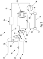
- Both figures show a gas chromatograph assembly 10 comprising a sample gas inlet 20 for introducing a sample gas to be analysed, a secondary gas inlet 40, being a reference gas inlet which is open to atmosphere.
- the gas chromatograph assembly 10 further comprises a gas chromatograph sensor 24, a gas chromatograph column 26, and a gas chromatograph bypass 28 parallel to the column 26.
- a gas chromatograph valve 30 is provided, being adapted to switch between the gas chromatograph column 26 and the gas chromatograph bypass 28 to conduct gas either through the gas chromatograph column 26 or the gas chromatograph bypass 28 into the gas chromatograph sensor 24.
- a secondary sensor assembly 12 in the form of an infrared sensor assembly is provided for measurement of the sample gas concentration.
- the secondary sensor assembly 12 comprises a secondary sensor assembly inlet 16 at a first end, and a secondary sensor assembly outlet 18 at a second end of the secondary sensor assembly 12.
- the sample gas inlet 20 and the secondary gas inlet 40 are connected in parallel to a gas modulation valve 42, which is adapted to alternatingly connect either of the sample gas inlet 20 and the secondary gas inlet 40 to the secondary sensor assembly 12.
- the sample gas inlet 20 is connected to the gas modulation valve 42 via a check valve 50.
- the gas chromatograph sensor 24 is connected to an exhaust outlet 22 via an exhaust line 32.
- the exhaust line 32 is connected to the gas flow path connecting the sample gas inlet 20 and the gas modulation valve 42, thereby forming a loop 52.
- the loop 52 comprises the gas modulation valve 42, the secondary gas sensor assembly 12, the gas chromatograph valve 30, an additional gas pump 54 in the gas flow path connecting the secondary sensor assembly 12 and the gas chromatograph sensor 24, the bypass 28, the gas chromatograph sensor 24 and the exhaust line 32.
- the exhaust line 32 and the loop 52 may be connected to respective separate outlets of the sensor 24.
- the loop 52 is adapted to circulate the gas mixture of the sample gas and of the secondary gas a number of times before measuring the sample gas concentration with the secondary gas sensor assembly 12. Once the sample gas concentration is sufficiently reduced, the gas chromatograph valve 30 switches from the gas chromatograph bypass to the gas chromatograph column 26 for a predetermined amount of time in order to inject a short gas pulse of the gas mixture into the column 26.
- the gas chromatograph valve 30 switches between the column 26 and the bypass 28.
- the gas chromatograph valve 30, the column 26 and the bypass 28 are comprised in the gas flow path connecting the secondary sensor outlet 18 with the gas chromatograph sensor 24. This gas flow path also comprises the additional gas pump 54.
- the gas chromatograph valve 30, the column 26 and the bypass 28 are comprised in the gas flow path connecting the gas modulation valve 42 and the secondary sensor assembly inlet 16.
Landscapes
- Physics & Mathematics (AREA)
- Health & Medical Sciences (AREA)
- Life Sciences & Earth Sciences (AREA)
- Chemical & Material Sciences (AREA)
- Analytical Chemistry (AREA)
- Biochemistry (AREA)
- General Health & Medical Sciences (AREA)
- General Physics & Mathematics (AREA)
- Immunology (AREA)
- Pathology (AREA)
- Sampling And Sample Adjustment (AREA)
- Investigating Or Analysing Materials By Optical Means (AREA)
Abstract
Description
- The invention concerns a method for adapting the concentration of a sample gas in a gas mixture to be analysed by a gas chromatograph assembly, as well as a gas chromatograph assembly for adapting the concentration of a sample gas to be analysed.
- Gas chromatography is employed to separate gas components from a gas mixture and to detect these separated gas components. This is achieved by injecting small amounts of the gas mixture into a tube shaped column. The column is typically either a narrow capillary tube, the inner surface of which is provided with a surface active coating or a slightly larger tube filled with a surface active powder, which in both cases is called the "stationary phase". A carrier gas, such as hydrogen, helium or air is employed to carry the amount of the gas mixture to be analysed through the column. The carrier gas is usually referred to as the "mobile phase." Thus, the gas mixture to be analysed follows the mobile phase through the stationary phase, thereby pushing the gas mixture slowly through the stationary phase. Lighter components of the gas mixture travel faster, so that different gas components of the injected gas pulse leave the column at different times and can thus be detected one by one. The arrival time or travel time of the gas components is used to identify these. A gas chromatograph sensor is used in order to measure the time of arrival or travel time of each gas component. Gas chromatography is used in the forensic science, medicine and environmental protection fields.
- Gas chromatography is also used in the field of gas leak detection, particularly for assessing whether a certain gas component measured on the ground surface originates from a leak in an underground pipeline carrying a natural gas. The main component of the natural gas and of gas from biological decay processes ("swamp gas") is methane. Swamp gas is produced when microorganisms digest biological waste. Before repair work for repairing a leak in a buried underground pipeline is initiated, it needs to be ensured that the gas detected at the ground surface does not originate from a swamp gas emission.
- This can be achieved by means of gas chromatography. In this regard, it needs to be considered that natural gas always contains a certain amount of ethane, while swamp gas never contains any amount of ethane. Thus, if ethane is detected via gas chromatography, this is an indication that the gas detected on a ground surface does not originate from swamp gas but rather from a gas leak in an underground pipeline carrying natural gas, such as methane.
- The concentration of sample gas in the gas sample analysed by the gas chromatograph is critical. On the one hand, the concentration needs to be high enough in order to achieve a sufficient measurement signal. On the other hand, the concentration must not exceed a certain value, in order to avoid overloading of the stationary phase within the gas chromatograph column. Overloading creates distorted peaks in the measurement signal and can lead to misinterpretation of the gas type, or can even result in covering or hiding peaks of several gas components. This is particularly critical for a simple column without any temperature control.
- The object of the invention is to provide a method for adapting the concentration of a sample gas in a gas mixture to be analysed by a gas chromatograph assembly. A gas chromatograph assembly for adapting the concentration of a sample gas in a gas mixture to be analysed shall also be provided.
- The subject matter of the invention is defined by each of
independent claims 1 and 12. - The gas chromatograph assembly of the invention comprises a sample gas inlet for introducing a sample gas to be analysed, a secondary gas inlet, as well as a gas chromatograph sensor, a gas chromatograph column, and a gas chromatograph bypass parallel to the column.
- According to the invention,
- a) an amount of sample gas is introduced into the gas chromatograph assembly through the sample gas inlet,
- b) an amount of secondary gas is introduced through the secondary gas inlet,
- c) the sample gas and the secondary gas are mixed to a gas mixture which is conducted via the gas chromatograph bypass,
- d) circulating the gas mixture in a gas conducting loop comprising the gas chromatograph bypass and the gas chromatograph sensor.
- e) steps b), c) and d) are repeated without step a) to gradually reduce the concentration of sample gas within the gas mixture until the concentration of sample gas within the gas mixture reaches a desired predetermined level, and
- f) the gas mixture thus obtained is analysed by means of gas chromatography employing the gas chromatograph column and the gas chromatograph sensor.
- In other words, a gas mixture is created from the sample gas which enters through the sample gas inlet, and from the secondary gas which enters through the secondary gas inlet. The gas mixture is conducted via the gas chromatograph bypass, such that the gas mixture can actually flow within the gas chromatograph assembly without being blocked by the column. The gas chromatograph bypass facilitates the mixing of the two gas components.
- The invention achieves a gradual reduction of the concentration of sample gas within the gas mixture by repeating the introduction of the secondary gas and the mixing of the newly introduced secondary gas with the gas mixture already present within the gas chromatograph assembly without further introducing sample gas. The reduction of the sample gas concentration is performed until the concentration of sample gas within the gas mixture reaches a desired predetermined level, at which a sufficient measurement signal from the gas chromatograph sensor is generated without overloading of the stationary phase in the column.
- The sample gas concentration is preferably measured during or before step d), i.e. before the introduction of sample gas or secondary gas is repeated, in order to determine whether the sample gas concentration has already reached the predetermined level. This measurement can be made with a secondary sensor assembly, such as an infrared sensor assembly. The sample gas introduced during step a) can be conducted through the secondary sensor assembly to the gas chromatograph sensor.
- As an alternative to the sample gas concentration measurement during or before step d), the repeating according to step d) is performed a predetermined number of times without measuring the sample gas concentration.
- The gas chromatograph assembly comprises a gas conducting loop comprising the gas chromatograph bypass and the gas chromatograph sensor, in order to achieve mixing of the sample gas and the secondary gas during circulation through the loop. In the case that the loop also comprises the secondary sensor assembly, the sample gas concentration can be measured at every cycle, or even continuously, in order to be able to measure and control the gradual increase or decrease of the sample gas concentration.
- The loop may comprise a gas modulation valve being adapted to alternatingly connect either of the sample gas inlet and the secondary gas inlet with the loop. In this example, the secondary gas inlet can be a reference gas inlet which is usually employed to compare the gas sample with a reference gas. In particular, the gas modulation valve may connect the sample gas inlet with the loop during step a) while separating the secondary/reference gas inlet from the loop. Likewise, during step b) the gas modulation valve connects the secondary gas inlet with the loop while separating the sample gas inlet from the loop.
- In a typical embodiment, the gas modulation valve connects the sample gas inlet and the secondary/reference gas inlet with the secondary sensor assembly, typically an infrared sensor assembly.
- The secondary sensor assembly comprises a secondary sensor assembly inlet at a first end of the secondary sensor assembly, and a secondary sensor assembly outlet at a second end of the secondary sensor assembly. During step a), the secondary sensor assembly inlet may be connected to the sample gas inlet, while the reference gas inlet is separated from the secondary sensor assembly inlet. Gas is then drawn from the sample gas inlet through the secondary sensor assembly, and conducted to the gas chromatograph sensor via the gas chromatograph bypass. Likewise, in step b), the secondary sensor assembly inlet may be connected to the reference gas inlet, while separating the sample gas inlet from the secondary sensor assembly inlet. Gas is then drawn from the reference gas inlet through the secondary sensor assembly.
- The gas mixture of the sample gas and the secondary gas (reference gas) may be circulated through a gas conducting loop comprising the secondary sensor assembly, the gas chromatograph sensor bypass, the gas chromatograph sensor, the gas modulation valve and a gas chromatograph valve.
- The gas chromatograph valve can be a switching valve adapted to switch between the gas chromatograph column and the gas chromatograph bypass to conduct gas either through the gas chromatograph column or through the gas chromatograph bypass into the gas chromatograph sensor.
- Preferably, during step c), both the sample gas inlet and the secondary inlet are separated from the loop. In particular, the secondary sensor assembly inlet may be separated from the reference gas inlet while still separating the sample gas inlet from the secondary sensor assembly inlet.
- In general, it is preferred that the gas mixture is allowed to circulate in the loop for some time to mix the secondary gas and the sample gas. In particular, the secondary gas may be air. In order to achieve this, the secondary inlet may be an inlet from open atmosphere, i.e. an inlet being open to atmosphere.
- A predetermined amount of the gas mixture may be injected into the gas chromatograph column by opening the gas chromatograph valve for a predetermined amount of time. After the gas chromatograph valve is closed, the gas chromatograph sensor/sensors may be purged by drawing air from either the sample gas inlet or the secondary/reference gas inlet, and conducting said air to the secondary sensor assembly and to the gas chromatograph sensor via the gas chromatograph bypass. Thereafter, the gas chromatograph valve may be opened and air can be drawn or pushed through the gas chromatograph column into the gas chromatograph sensor for analysing the gas mixture by means of gas chromatography.
- In general, the invention allows to dilute the sample gas in repeated cycles, i.e. gradually, in a controlled manner. After measuring the sample gas concentration, the entire system may first be purged, and then the gas modulation valve may be used to draw a number of short pulses from the sample gas inlet and thereby inject sample gas in the stream of gas mixture, or air stream drawn from the secondary inlet. The stream of sample gas and secondary gas is then allowed to circulate in the loop for mixing before injecting a small amount of the obtained gas mixture into the gas chromatograph column.
- In the following, exemplary embodiments of the invention will be explained with reference to the figures. In particular,
-
Fig. 1 shows the general layout of a first embodiment and -
Fig. 2 shows a general layout of a second embodiment. - Both figures show a
gas chromatograph assembly 10 comprising asample gas inlet 20 for introducing a sample gas to be analysed, asecondary gas inlet 40, being a reference gas inlet which is open to atmosphere. Thegas chromatograph assembly 10 further comprises agas chromatograph sensor 24, agas chromatograph column 26, and agas chromatograph bypass 28 parallel to thecolumn 26. - A
gas chromatograph valve 30 is provided, being adapted to switch between thegas chromatograph column 26 and thegas chromatograph bypass 28 to conduct gas either through thegas chromatograph column 26 or thegas chromatograph bypass 28 into thegas chromatograph sensor 24. - A
secondary sensor assembly 12 in the form of an infrared sensor assembly is provided for measurement of the sample gas concentration. Thesecondary sensor assembly 12 comprises a secondarysensor assembly inlet 16 at a first end, and a secondarysensor assembly outlet 18 at a second end of thesecondary sensor assembly 12. - The
sample gas inlet 20 and thesecondary gas inlet 40 are connected in parallel to agas modulation valve 42, which is adapted to alternatingly connect either of thesample gas inlet 20 and thesecondary gas inlet 40 to thesecondary sensor assembly 12. Thesample gas inlet 20 is connected to thegas modulation valve 42 via acheck valve 50. - The
gas chromatograph sensor 24 is connected to anexhaust outlet 22 via anexhaust line 32. Theexhaust line 32 is connected to the gas flow path connecting thesample gas inlet 20 and thegas modulation valve 42, thereby forming aloop 52. In particular, theloop 52 comprises thegas modulation valve 42, the secondarygas sensor assembly 12, thegas chromatograph valve 30, anadditional gas pump 54 in the gas flow path connecting thesecondary sensor assembly 12 and thegas chromatograph sensor 24, thebypass 28, thegas chromatograph sensor 24 and theexhaust line 32. Alternatively, theexhaust line 32 and theloop 52 may be connected to respective separate outlets of thesensor 24. - The
loop 52 is adapted to circulate the gas mixture of the sample gas and of the secondary gas a number of times before measuring the sample gas concentration with the secondarygas sensor assembly 12. Once the sample gas concentration is sufficiently reduced, thegas chromatograph valve 30 switches from the gas chromatograph bypass to thegas chromatograph column 26 for a predetermined amount of time in order to inject a short gas pulse of the gas mixture into thecolumn 26. - In both embodiments, the
gas chromatograph valve 30 switches between thecolumn 26 and thebypass 28. In the embodiment ofFig. 1 , thegas chromatograph valve 30, thecolumn 26 and thebypass 28 are comprised in the gas flow path connecting thesecondary sensor outlet 18 with thegas chromatograph sensor 24. This gas flow path also comprises theadditional gas pump 54. In the embodiment according toFig. 2 , thegas chromatograph valve 30, thecolumn 26 and thebypass 28 are comprised in the gas flow path connecting thegas modulation valve 42 and the secondarysensor assembly inlet 16.
Claims (14)
- Method for adapting the concentration of a sample gas in a gas mixture to be analysed by a gas chromatograph assembly (10), the gas chromatograph assembly (10) comprisinga sample gas inlet (20) for introducing a sample gas to be analysed,a secondary gas inlet (40),a gas chromatograph sensor (24), a gas chromatograph column (26), and a gas chromatograph bypass (28) parallel to the column (26),characterized bya) introducing an amount of sample gas through the sample gas inlet (20),b) introducing an amount of secondary gas through the secondary gas inlet (40),c) mixing the sample gas and the secondary gas to a gas mixture and conducting the gas mixture via the gas chromatograph bypass (28),d) circulating the gas mixture in a gas conducting loop (52) comprising the gas chromatograph bypass (28) and the gas chromatograph sensor (24),e) repeating steps b), c) and d) without step a) to gradually reduce the concentration of sample gas within the gas mixture until the concentration of sample gas within the gas mixture reaches a desired predetermined level,f) analysing the gas mixture thus obtained by means of gas chromatography employing the gas chromatograph column (26) and the gas chromatograph sensor (24).
- The method according to claim 1, wherein the sample gas concentration is measured during or before step d) to determine whether the sample gas concentration has reached the predetermined level.
- The method according to claim 2, wherein the measuring of the sample gas concentration during or before step d) is performed with a secondary sensor assembly (12), such as an infrared sensor assembly.
- The method according to claim 3, wherein during step a) the sample gas from the sample gas inlet (20) is conducted through the secondary sensor assembly (12) and to the gas chromatograph sensor (24).
- The method according to claim 3 or 4, wherein the loop (52) further comprises the secondary sensor assembly (12).
- The method according to claim 1, wherein the repeating according to step d) is performed a predetermined number of times without measuring the sample gas concentration.
- The method according to one of claims 1 - 6, wherein the loop (52) comprises a gas modulation valve (42) adapted to alternatingly connect either of the sample gas inlet (20) and the secondary gas inlet (40) with the loop (52).
- The method according to claim 7, wherein during step a) the gas modulation valve (42) connects the sample gas inlet (20) with the loop (52) while separating the secondary inlet (40) from the loop (52).
- The method according to claim 7 or 8, wherein during step b) the gas modulation valve (42) connects the secondary gas inlet (40) with the loop (52) while separating the sample gas inlet (20) from the loop (52).
- The method according to one of claims 1 - 9, wherein during step c) both the sample gas inlet (20) and the secondary inlet (40) are separated from the loop (52).
- Gas chromatograph assembly (10) for adapting the concentration of a sample gas in a gas mixture to be analysed according to the method of one of claims 1-11, comprising
a sample gas inlet (20) for introducing a sample gas to be analysed,
a secondary gas inlet (40),
a gas chromatograph sensor (24), a gas chromatograph column (26), and a gas chromatograph bypass (28) arranged parallel to the column (26) for bypassing the same, and
a gas conducting loop (52) comprising the gas chromatograph bypass (28) and the gas chromatograph sensor (24). - The gas chromatograph assembly (10) of claim 11, further comprising a secondary sensor assembly (12), such as an infrared sensor assembly, for measuring the sample gas concentration during or before step d).
- The gas chromatograph assembly (10) of claim 11 or 12, wherein the loop (52) comprises a gas modulation valve (42) adapted to alternatingly connect either of the sample gas inlet (20) and the secondary gas inlet (40) with the loop (52).
- The method according to one of claims 1-10 or the gas chromatograph assembly (10) according to one of claims 11 - 13, wherein the loop (52) comprises a gas chromatograph valve (30) adapted to switch between the gas chromatograph column (26) and the gas chromatograph bypass (28) to conduct gas either through the gas chromatograph column (26) or the gas chromatograph bypass (28) into the gas chromatograph sensor (24).
Priority Applications (5)
| Application Number | Priority Date | Filing Date | Title |
|---|---|---|---|
| EP18185795.4A EP3599463B1 (en) | 2018-07-26 | 2018-07-26 | Method for adapting the concentration of sample gas in a gas mixture to be analysed by a gas chromatograph assembly, and chromatograph assembly therefore |
| JP2021504195A JP7359838B2 (en) | 2018-07-26 | 2019-07-26 | Method for adjusting the concentration of a sample gas in a gas mixture analyzed by a gas chromatograph assembly and the chromatograph assembly used therefor |
| PCT/EP2019/070160 WO2020021057A1 (en) | 2018-07-26 | 2019-07-26 | Method for adapting the concentration of a sample gas in a gas mixture to be analysed by a gas chromatograph assembly, and chromatograph assembly therefore |
| US17/262,854 US11982651B2 (en) | 2018-07-26 | 2019-07-26 | Method for adapting the concentration of a sample gas in a gas mixture to be analysed by a gas chromatograph assembly, and chromatograph assembly therefore |
| CN201980046076.9A CN112384798B (en) | 2018-07-26 | 2019-07-26 | Method for adjusting concentration of sample gas and gas chromatograph assembly |
Applications Claiming Priority (1)
| Application Number | Priority Date | Filing Date | Title |
|---|---|---|---|
| EP18185795.4A EP3599463B1 (en) | 2018-07-26 | 2018-07-26 | Method for adapting the concentration of sample gas in a gas mixture to be analysed by a gas chromatograph assembly, and chromatograph assembly therefore |
Publications (2)
| Publication Number | Publication Date |
|---|---|
| EP3599463A1 true EP3599463A1 (en) | 2020-01-29 |
| EP3599463B1 EP3599463B1 (en) | 2023-05-10 |
Family
ID=63108419
Family Applications (1)
| Application Number | Title | Priority Date | Filing Date |
|---|---|---|---|
| EP18185795.4A Active EP3599463B1 (en) | 2018-07-26 | 2018-07-26 | Method for adapting the concentration of sample gas in a gas mixture to be analysed by a gas chromatograph assembly, and chromatograph assembly therefore |
Country Status (5)
| Country | Link |
|---|---|
| US (1) | US11982651B2 (en) |
| EP (1) | EP3599463B1 (en) |
| JP (1) | JP7359838B2 (en) |
| CN (1) | CN112384798B (en) |
| WO (1) | WO2020021057A1 (en) |
Cited By (1)
| Publication number | Priority date | Publication date | Assignee | Title |
|---|---|---|---|---|
| EP3848703A1 (en) * | 2020-01-10 | 2021-07-14 | Inficon GmbH | Method for adapting the concentration of a sample gas in a gas mixture to be analysed by a gas chromatograph assembly, and chromatograph assembly therefor |
Families Citing this family (1)
| Publication number | Priority date | Publication date | Assignee | Title |
|---|---|---|---|---|
| CN115561339A (en) * | 2022-06-15 | 2023-01-03 | 苏州海思利福生物医疗科技有限公司 | Expiration combined detection device and method and detection medicine |
Citations (5)
| Publication number | Priority date | Publication date | Assignee | Title |
|---|---|---|---|---|
| WO2013039487A1 (en) * | 2011-09-13 | 2013-03-21 | Empire Technology Development Llc | Miniaturized gas chromatograph |
| US20160061798A1 (en) * | 2013-04-15 | 2016-03-03 | Thermo Fisher Scientific (Bremen) Gmbh | Gas Inlet System for Isotope Ratio Analyzer and Method of Determining an Isotope Ratio |
| US20160320362A1 (en) * | 2015-04-30 | 2016-11-03 | Thermo Fisher Scientific (Bremen) Gmbh | Method and Apparatus for Reducing Gas Consumption |
| US20170122920A1 (en) * | 2015-10-31 | 2017-05-04 | Prism Analytical Technologies, Inc. | Coupled Analytical Instruments for Dual Mode FTIR/GC-FTIR |
| US20170241961A1 (en) * | 2016-02-22 | 2017-08-24 | University Of Utah Research Foundation | Micro Circulatory Gas Chromatography System and Method |
Family Cites Families (23)
| Publication number | Priority date | Publication date | Assignee | Title |
|---|---|---|---|---|
| JPS554528A (en) * | 1978-06-27 | 1980-01-14 | Sumitomo Bakelite Co Ltd | Method and apparatus for measuring gas concentration |
| US4629705A (en) * | 1984-05-31 | 1986-12-16 | The Dow Chemical Company | Indirect-photometric chromatography done in and with a variable capacity weakly basic or acidic ion exchange column |
| JPH06130045A (en) | 1992-10-21 | 1994-05-13 | Tokyo Gas Chem Kk | Diluter |
| JPH08160025A (en) * | 1994-12-05 | 1996-06-21 | Yamatake Honeywell Co Ltd | Gas chromatograph adjustment method |
| US5826632A (en) * | 1997-05-30 | 1998-10-27 | The Boc Group, Inc. | Dynamic gas cylinder filling process |
| JP2002243599A (en) | 2001-02-09 | 2002-08-28 | Horiba Ltd | Gas dilution device |
| US7063097B2 (en) * | 2003-03-28 | 2006-06-20 | Advanced Technology Materials, Inc. | In-situ gas blending and dilution system for delivery of dilute gas at a predetermined concentration |
| CN100458267C (en) | 2007-01-15 | 2009-02-04 | 同济大学 | Air distributing device |
| JP5521372B2 (en) | 2009-04-03 | 2014-06-11 | セントラル硝子株式会社 | In-situ gas mixing and dilution system for fluorine gas |
| JP2011038994A (en) | 2009-08-18 | 2011-02-24 | Honda Motor Co Ltd | Gas analyzer |
| CN201886003U (en) | 2010-12-24 | 2011-06-29 | 杭州申昊信息科技有限公司 | Gas concentration calibration device used for transformer oil detection |
| DE102011006452A1 (en) * | 2011-03-30 | 2012-10-04 | Siemens Aktiengesellschaft | Method for the chromatographic analysis of a gas mixture containing hydrogen |
| DE102011078156A1 (en) * | 2011-06-28 | 2013-01-03 | Siemens Aktiengesellschaft | Gas chromatograph and method for gas chromatographic analysis of a gas mixture |
| CN203519401U (en) | 2013-06-05 | 2014-04-02 | 中国石油化工股份有限公司 | Gas concentration diluting device for well logging |
| CN103331125B (en) | 2013-07-23 | 2015-07-15 | 重庆大学 | High-precision gas distribution instrument |
| GB2520067B (en) * | 2013-11-08 | 2016-07-27 | Thermo Fisher Scient (Bremen) Gmbh | Gas inlet system for isotope ratio spectrometer |
| CN205263040U (en) | 2015-12-03 | 2016-05-25 | 青海黄河上游水电开发有限责任公司新能源分公司 | Gas chromatograph appearance and gaseous sampling device thereof |
| CN107525708B (en) | 2016-06-21 | 2019-12-24 | 上海炫一电气有限公司 | Sample gas dilution system capable of working in negative pressure environment |
| CN106645522A (en) * | 2016-08-31 | 2017-05-10 | 武汉市天虹仪表有限责任公司 | On-line volatile organic compound monitoring system with automatic calibration function |
| CN206020354U (en) | 2016-09-21 | 2017-03-15 | 贵州省环境科学研究设计院 | A kind of gas chromatogram dilutes air intake installation |
| CN206450640U (en) | 2016-12-28 | 2017-08-29 | 浙江富春江环保科技研究有限公司 | Gas sample introduction regulating system for dioxin on-line checking |
| CN107192791A (en) | 2017-05-16 | 2017-09-22 | 湖北锐意自控系统有限公司 | A kind of gas analyzing apparatus and method |
| CN207366326U (en) | 2017-11-13 | 2018-05-15 | 广州顺斡仪表科技有限公司 | Gas sampling dynamic dilution system |
-
2018
- 2018-07-26 EP EP18185795.4A patent/EP3599463B1/en active Active
-
2019
- 2019-07-26 WO PCT/EP2019/070160 patent/WO2020021057A1/en not_active Ceased
- 2019-07-26 US US17/262,854 patent/US11982651B2/en active Active
- 2019-07-26 JP JP2021504195A patent/JP7359838B2/en active Active
- 2019-07-26 CN CN201980046076.9A patent/CN112384798B/en active Active
Patent Citations (5)
| Publication number | Priority date | Publication date | Assignee | Title |
|---|---|---|---|---|
| WO2013039487A1 (en) * | 2011-09-13 | 2013-03-21 | Empire Technology Development Llc | Miniaturized gas chromatograph |
| US20160061798A1 (en) * | 2013-04-15 | 2016-03-03 | Thermo Fisher Scientific (Bremen) Gmbh | Gas Inlet System for Isotope Ratio Analyzer and Method of Determining an Isotope Ratio |
| US20160320362A1 (en) * | 2015-04-30 | 2016-11-03 | Thermo Fisher Scientific (Bremen) Gmbh | Method and Apparatus for Reducing Gas Consumption |
| US20170122920A1 (en) * | 2015-10-31 | 2017-05-04 | Prism Analytical Technologies, Inc. | Coupled Analytical Instruments for Dual Mode FTIR/GC-FTIR |
| US20170241961A1 (en) * | 2016-02-22 | 2017-08-24 | University Of Utah Research Foundation | Micro Circulatory Gas Chromatography System and Method |
Cited By (3)
| Publication number | Priority date | Publication date | Assignee | Title |
|---|---|---|---|---|
| EP3848703A1 (en) * | 2020-01-10 | 2021-07-14 | Inficon GmbH | Method for adapting the concentration of a sample gas in a gas mixture to be analysed by a gas chromatograph assembly, and chromatograph assembly therefor |
| WO2021139953A1 (en) * | 2020-01-10 | 2021-07-15 | Inficon Gmbh | Method for adapting the concentration of a sample gas in a gas mixture to be analysed by a gas chromatograph assembly, and chromatograph assembly therefor |
| US12044664B2 (en) | 2020-01-10 | 2024-07-23 | Inficon Gmbh | Method for adapting the concentration of a sample gas in a gas mixture to be analysed by a gas chromatograph assembly, and chromatograph assembly therefore |
Also Published As
| Publication number | Publication date |
|---|---|
| WO2020021057A1 (en) | 2020-01-30 |
| JP7359838B2 (en) | 2023-10-11 |
| JP2021531471A (en) | 2021-11-18 |
| US20210318271A1 (en) | 2021-10-14 |
| CN112384798A (en) | 2021-02-19 |
| CN112384798B (en) | 2024-02-09 |
| US11982651B2 (en) | 2024-05-14 |
| EP3599463B1 (en) | 2023-05-10 |
Similar Documents
| Publication | Publication Date | Title |
|---|---|---|
| CN104569233B (en) | ion mobility spectrometer system | |
| US11982651B2 (en) | Method for adapting the concentration of a sample gas in a gas mixture to be analysed by a gas chromatograph assembly, and chromatograph assembly therefore | |
| US11067182B1 (en) | Valve for controlled shuttle of liquid into microtiter plates and mixing | |
| CN104634901B (en) | A kind of gas sample injection device and its application | |
| US20090159795A1 (en) | Device for the analysis of isotope ratios | |
| CN102253158B (en) | Ion chromatography circulating column switching analysis system and detection method thereof | |
| BR112012011917B1 (en) | METHOD OF DETECTION OF AN IONIC MOBILITY SPECTROMETER | |
| CN105445389B (en) | It calibrates chromatographic system and analyzes the automated method of sample | |
| CN104458986A (en) | Gas chromatography multichannel sample introduction system and realized atmosphere detection method thereof | |
| CN114609281A (en) | System and method for measuring content of impurity components in perfluoroisobutyronitrile | |
| CN202305489U (en) | Chromatographic instrument for detecting failure of SF6 electric equipment | |
| CN114609283B (en) | A system and method for measuring decomposition products in perfluoroisobutyronitrile | |
| CN113237986B (en) | Liquid Chromatograph and Method for Performing Analysis | |
| CN102246032A (en) | Method and apparatus for gas chromatographic analysis of a gas mixture | |
| CN109844519B (en) | Gas chromatograph | |
| US12044664B2 (en) | Method for adapting the concentration of a sample gas in a gas mixture to be analysed by a gas chromatograph assembly, and chromatograph assembly therefore | |
| US12130267B2 (en) | Analyzing method for azo compound | |
| WO2020202868A1 (en) | Gas analysis device and gas sampling device | |
| CN106885864A (en) | The more bundles of capillaries post and flight time mass spectrum of sampling sample introduction integration are used in conjunction device | |
| CN104267198A (en) | Automatic calibration device and method for volatile organic compound analyzer | |
| JP6117601B2 (en) | Sample gas diverter | |
| CN118130632A (en) | Gas chromatography rapid analysis system in petroleum exploration engineering | |
| JPH1096717A (en) | Method and device for determining kind of gas | |
| JPS62190464A (en) | Gas chromatograph | |
| CN204925057U (en) | Survey device of post switching time parameter based on switching column technique |
Legal Events
| Date | Code | Title | Description |
|---|---|---|---|
| PUAI | Public reference made under article 153(3) epc to a published international application that has entered the european phase |
Free format text: ORIGINAL CODE: 0009012 |
|
| STAA | Information on the status of an ep patent application or granted ep patent |
Free format text: STATUS: THE APPLICATION HAS BEEN PUBLISHED |
|
| AK | Designated contracting states |
Kind code of ref document: A1 Designated state(s): AL AT BE BG CH CY CZ DE DK EE ES FI FR GB GR HR HU IE IS IT LI LT LU LV MC MK MT NL NO PL PT RO RS SE SI SK SM TR |
|
| AX | Request for extension of the european patent |
Extension state: BA ME |
|
| STAA | Information on the status of an ep patent application or granted ep patent |
Free format text: STATUS: REQUEST FOR EXAMINATION WAS MADE |
|
| 17P | Request for examination filed |
Effective date: 20200715 |
|
| RBV | Designated contracting states (corrected) |
Designated state(s): AL AT BE BG CH CY CZ DE DK EE ES FI FR GB GR HR HU IE IS IT LI LT LU LV MC MK MT NL NO PL PT RO RS SE SI SK SM TR |
|
| GRAP | Despatch of communication of intention to grant a patent |
Free format text: ORIGINAL CODE: EPIDOSNIGR1 |
|
| STAA | Information on the status of an ep patent application or granted ep patent |
Free format text: STATUS: GRANT OF PATENT IS INTENDED |
|
| INTG | Intention to grant announced |
Effective date: 20221130 |
|
| GRAS | Grant fee paid |
Free format text: ORIGINAL CODE: EPIDOSNIGR3 |
|
| GRAA | (expected) grant |
Free format text: ORIGINAL CODE: 0009210 |
|
| STAA | Information on the status of an ep patent application or granted ep patent |
Free format text: STATUS: THE PATENT HAS BEEN GRANTED |
|
| AK | Designated contracting states |
Kind code of ref document: B1 Designated state(s): AL AT BE BG CH CY CZ DE DK EE ES FI FR GB GR HR HU IE IS IT LI LT LU LV MC MK MT NL NO PL PT RO RS SE SI SK SM TR |
|
| REG | Reference to a national code |
Ref country code: GB Ref legal event code: FG4D |
|
| REG | Reference to a national code |
Ref country code: AT Ref legal event code: REF Ref document number: 1567161 Country of ref document: AT Kind code of ref document: T Effective date: 20230515 Ref country code: CH Ref legal event code: EP |
|
| REG | Reference to a national code |
Ref country code: DE Ref legal event code: R096 Ref document number: 602018049484 Country of ref document: DE |
|
| REG | Reference to a national code |
Ref country code: IE Ref legal event code: FG4D |
|
| P01 | Opt-out of the competence of the unified patent court (upc) registered |
Effective date: 20230524 |
|
| REG | Reference to a national code |
Ref country code: NL Ref legal event code: FP |
|
| REG | Reference to a national code |
Ref country code: LT Ref legal event code: MG9D |
|
| REG | Reference to a national code |
Ref country code: AT Ref legal event code: MK05 Ref document number: 1567161 Country of ref document: AT Kind code of ref document: T Effective date: 20230510 |
|
| PG25 | Lapsed in a contracting state [announced via postgrant information from national office to epo] |
Ref country code: SE Free format text: LAPSE BECAUSE OF FAILURE TO SUBMIT A TRANSLATION OF THE DESCRIPTION OR TO PAY THE FEE WITHIN THE PRESCRIBED TIME-LIMIT Effective date: 20230510 Ref country code: PT Free format text: LAPSE BECAUSE OF FAILURE TO SUBMIT A TRANSLATION OF THE DESCRIPTION OR TO PAY THE FEE WITHIN THE PRESCRIBED TIME-LIMIT Effective date: 20230911 Ref country code: NO Free format text: LAPSE BECAUSE OF FAILURE TO SUBMIT A TRANSLATION OF THE DESCRIPTION OR TO PAY THE FEE WITHIN THE PRESCRIBED TIME-LIMIT Effective date: 20230810 Ref country code: ES Free format text: LAPSE BECAUSE OF FAILURE TO SUBMIT A TRANSLATION OF THE DESCRIPTION OR TO PAY THE FEE WITHIN THE PRESCRIBED TIME-LIMIT Effective date: 20230510 Ref country code: AT Free format text: LAPSE BECAUSE OF FAILURE TO SUBMIT A TRANSLATION OF THE DESCRIPTION OR TO PAY THE FEE WITHIN THE PRESCRIBED TIME-LIMIT Effective date: 20230510 |
|
| PG25 | Lapsed in a contracting state [announced via postgrant information from national office to epo] |
Ref country code: RS Free format text: LAPSE BECAUSE OF FAILURE TO SUBMIT A TRANSLATION OF THE DESCRIPTION OR TO PAY THE FEE WITHIN THE PRESCRIBED TIME-LIMIT Effective date: 20230510 Ref country code: PL Free format text: LAPSE BECAUSE OF FAILURE TO SUBMIT A TRANSLATION OF THE DESCRIPTION OR TO PAY THE FEE WITHIN THE PRESCRIBED TIME-LIMIT Effective date: 20230510 Ref country code: LV Free format text: LAPSE BECAUSE OF FAILURE TO SUBMIT A TRANSLATION OF THE DESCRIPTION OR TO PAY THE FEE WITHIN THE PRESCRIBED TIME-LIMIT Effective date: 20230510 Ref country code: LT Free format text: LAPSE BECAUSE OF FAILURE TO SUBMIT A TRANSLATION OF THE DESCRIPTION OR TO PAY THE FEE WITHIN THE PRESCRIBED TIME-LIMIT Effective date: 20230510 Ref country code: IS Free format text: LAPSE BECAUSE OF FAILURE TO SUBMIT A TRANSLATION OF THE DESCRIPTION OR TO PAY THE FEE WITHIN THE PRESCRIBED TIME-LIMIT Effective date: 20230910 Ref country code: HR Free format text: LAPSE BECAUSE OF FAILURE TO SUBMIT A TRANSLATION OF THE DESCRIPTION OR TO PAY THE FEE WITHIN THE PRESCRIBED TIME-LIMIT Effective date: 20230510 Ref country code: GR Free format text: LAPSE BECAUSE OF FAILURE TO SUBMIT A TRANSLATION OF THE DESCRIPTION OR TO PAY THE FEE WITHIN THE PRESCRIBED TIME-LIMIT Effective date: 20230811 |
|
| PG25 | Lapsed in a contracting state [announced via postgrant information from national office to epo] |
Ref country code: FI Free format text: LAPSE BECAUSE OF FAILURE TO SUBMIT A TRANSLATION OF THE DESCRIPTION OR TO PAY THE FEE WITHIN THE PRESCRIBED TIME-LIMIT Effective date: 20230510 |
|
| PG25 | Lapsed in a contracting state [announced via postgrant information from national office to epo] |
Ref country code: SK Free format text: LAPSE BECAUSE OF FAILURE TO SUBMIT A TRANSLATION OF THE DESCRIPTION OR TO PAY THE FEE WITHIN THE PRESCRIBED TIME-LIMIT Effective date: 20230510 |
|
| PG25 | Lapsed in a contracting state [announced via postgrant information from national office to epo] |
Ref country code: SM Free format text: LAPSE BECAUSE OF FAILURE TO SUBMIT A TRANSLATION OF THE DESCRIPTION OR TO PAY THE FEE WITHIN THE PRESCRIBED TIME-LIMIT Effective date: 20230510 Ref country code: SK Free format text: LAPSE BECAUSE OF FAILURE TO SUBMIT A TRANSLATION OF THE DESCRIPTION OR TO PAY THE FEE WITHIN THE PRESCRIBED TIME-LIMIT Effective date: 20230510 Ref country code: RO Free format text: LAPSE BECAUSE OF FAILURE TO SUBMIT A TRANSLATION OF THE DESCRIPTION OR TO PAY THE FEE WITHIN THE PRESCRIBED TIME-LIMIT Effective date: 20230510 Ref country code: EE Free format text: LAPSE BECAUSE OF FAILURE TO SUBMIT A TRANSLATION OF THE DESCRIPTION OR TO PAY THE FEE WITHIN THE PRESCRIBED TIME-LIMIT Effective date: 20230510 Ref country code: DK Free format text: LAPSE BECAUSE OF FAILURE TO SUBMIT A TRANSLATION OF THE DESCRIPTION OR TO PAY THE FEE WITHIN THE PRESCRIBED TIME-LIMIT Effective date: 20230510 Ref country code: CZ Free format text: LAPSE BECAUSE OF FAILURE TO SUBMIT A TRANSLATION OF THE DESCRIPTION OR TO PAY THE FEE WITHIN THE PRESCRIBED TIME-LIMIT Effective date: 20230510 |
|
| REG | Reference to a national code |
Ref country code: DE Ref legal event code: R097 Ref document number: 602018049484 Country of ref document: DE |
|
| PG25 | Lapsed in a contracting state [announced via postgrant information from national office to epo] |
Ref country code: MC Free format text: LAPSE BECAUSE OF FAILURE TO SUBMIT A TRANSLATION OF THE DESCRIPTION OR TO PAY THE FEE WITHIN THE PRESCRIBED TIME-LIMIT Effective date: 20230510 |
|
| PG25 | Lapsed in a contracting state [announced via postgrant information from national office to epo] |
Ref country code: MC Free format text: LAPSE BECAUSE OF FAILURE TO SUBMIT A TRANSLATION OF THE DESCRIPTION OR TO PAY THE FEE WITHIN THE PRESCRIBED TIME-LIMIT Effective date: 20230510 |
|
| REG | Reference to a national code |
Ref country code: CH Ref legal event code: PL |
|
| PLBE | No opposition filed within time limit |
Free format text: ORIGINAL CODE: 0009261 |
|
| STAA | Information on the status of an ep patent application or granted ep patent |
Free format text: STATUS: NO OPPOSITION FILED WITHIN TIME LIMIT |
|
| REG | Reference to a national code |
Ref country code: BE Ref legal event code: MM Effective date: 20230731 |
|
| PG25 | Lapsed in a contracting state [announced via postgrant information from national office to epo] |
Ref country code: LU Free format text: LAPSE BECAUSE OF NON-PAYMENT OF DUE FEES Effective date: 20230726 |
|
| PG25 | Lapsed in a contracting state [announced via postgrant information from national office to epo] |
Ref country code: LU Free format text: LAPSE BECAUSE OF NON-PAYMENT OF DUE FEES Effective date: 20230726 |
|
| 26N | No opposition filed |
Effective date: 20240213 |
|
| REG | Reference to a national code |
Ref country code: IE Ref legal event code: MM4A |
|
| PG25 | Lapsed in a contracting state [announced via postgrant information from national office to epo] |
Ref country code: CH Free format text: LAPSE BECAUSE OF NON-PAYMENT OF DUE FEES Effective date: 20230731 |
|
| PG25 | Lapsed in a contracting state [announced via postgrant information from national office to epo] |
Ref country code: SI Free format text: LAPSE BECAUSE OF FAILURE TO SUBMIT A TRANSLATION OF THE DESCRIPTION OR TO PAY THE FEE WITHIN THE PRESCRIBED TIME-LIMIT Effective date: 20230510 |
|
| PG25 | Lapsed in a contracting state [announced via postgrant information from national office to epo] |
Ref country code: SI Free format text: LAPSE BECAUSE OF FAILURE TO SUBMIT A TRANSLATION OF THE DESCRIPTION OR TO PAY THE FEE WITHIN THE PRESCRIBED TIME-LIMIT Effective date: 20230510 Ref country code: BE Free format text: LAPSE BECAUSE OF NON-PAYMENT OF DUE FEES Effective date: 20230731 |
|
| PG25 | Lapsed in a contracting state [announced via postgrant information from national office to epo] |
Ref country code: IE Free format text: LAPSE BECAUSE OF NON-PAYMENT OF DUE FEES Effective date: 20230726 |
|
| PG25 | Lapsed in a contracting state [announced via postgrant information from national office to epo] |
Ref country code: IE Free format text: LAPSE BECAUSE OF NON-PAYMENT OF DUE FEES Effective date: 20230726 |
|
| PG25 | Lapsed in a contracting state [announced via postgrant information from national office to epo] |
Ref country code: BG Free format text: LAPSE BECAUSE OF FAILURE TO SUBMIT A TRANSLATION OF THE DESCRIPTION OR TO PAY THE FEE WITHIN THE PRESCRIBED TIME-LIMIT Effective date: 20230510 |
|
| PG25 | Lapsed in a contracting state [announced via postgrant information from national office to epo] |
Ref country code: BG Free format text: LAPSE BECAUSE OF FAILURE TO SUBMIT A TRANSLATION OF THE DESCRIPTION OR TO PAY THE FEE WITHIN THE PRESCRIBED TIME-LIMIT Effective date: 20230510 |
|
| PG25 | Lapsed in a contracting state [announced via postgrant information from national office to epo] |
Ref country code: CY Free format text: LAPSE BECAUSE OF FAILURE TO SUBMIT A TRANSLATION OF THE DESCRIPTION OR TO PAY THE FEE WITHIN THE PRESCRIBED TIME-LIMIT; INVALID AB INITIO Effective date: 20180726 |
|
| PG25 | Lapsed in a contracting state [announced via postgrant information from national office to epo] |
Ref country code: HU Free format text: LAPSE BECAUSE OF FAILURE TO SUBMIT A TRANSLATION OF THE DESCRIPTION OR TO PAY THE FEE WITHIN THE PRESCRIBED TIME-LIMIT; INVALID AB INITIO Effective date: 20180726 |
|
| PGFP | Annual fee paid to national office [announced via postgrant information from national office to epo] |
Ref country code: NL Payment date: 20250723 Year of fee payment: 8 |
|
| PGFP | Annual fee paid to national office [announced via postgrant information from national office to epo] |
Ref country code: DE Payment date: 20250717 Year of fee payment: 8 |
|
| PGFP | Annual fee paid to national office [announced via postgrant information from national office to epo] |
Ref country code: IT Payment date: 20250731 Year of fee payment: 8 |
|
| PGFP | Annual fee paid to national office [announced via postgrant information from national office to epo] |
Ref country code: GB Payment date: 20250724 Year of fee payment: 8 |
|
| PGFP | Annual fee paid to national office [announced via postgrant information from national office to epo] |
Ref country code: FR Payment date: 20250723 Year of fee payment: 8 |
|
| PG25 | Lapsed in a contracting state [announced via postgrant information from national office to epo] |
Ref country code: TR Free format text: LAPSE BECAUSE OF FAILURE TO SUBMIT A TRANSLATION OF THE DESCRIPTION OR TO PAY THE FEE WITHIN THE PRESCRIBED TIME-LIMIT Effective date: 20230510 |