EP3599159A1 - Lift fan with diffuser duct - Google Patents
Lift fan with diffuser duct Download PDFInfo
- Publication number
- EP3599159A1 EP3599159A1 EP19187775.2A EP19187775A EP3599159A1 EP 3599159 A1 EP3599159 A1 EP 3599159A1 EP 19187775 A EP19187775 A EP 19187775A EP 3599159 A1 EP3599159 A1 EP 3599159A1
- Authority
- EP
- European Patent Office
- Prior art keywords
- flow area
- duct
- flow
- splitters
- rotor
- Prior art date
- Legal status (The legal status is an assumption and is not a legal conclusion. Google has not performed a legal analysis and makes no representation as to the accuracy of the status listed.)
- Granted
Links
Images


Classifications
-
- B—PERFORMING OPERATIONS; TRANSPORTING
- B64—AIRCRAFT; AVIATION; COSMONAUTICS
- B64C—AEROPLANES; HELICOPTERS
- B64C29/00—Aircraft capable of landing or taking-off vertically, e.g. vertical take-off and landing [VTOL] aircraft
- B64C29/0008—Aircraft capable of landing or taking-off vertically, e.g. vertical take-off and landing [VTOL] aircraft having its flight directional axis horizontal when grounded
- B64C29/0016—Aircraft capable of landing or taking-off vertically, e.g. vertical take-off and landing [VTOL] aircraft having its flight directional axis horizontal when grounded the lift during taking-off being created by free or ducted propellers or by blowers
- B64C29/0025—Aircraft capable of landing or taking-off vertically, e.g. vertical take-off and landing [VTOL] aircraft having its flight directional axis horizontal when grounded the lift during taking-off being created by free or ducted propellers or by blowers the propellers being fixed relative to the fuselage
-
- B—PERFORMING OPERATIONS; TRANSPORTING
- B64—AIRCRAFT; AVIATION; COSMONAUTICS
- B64C—AEROPLANES; HELICOPTERS
- B64C11/00—Propellers, e.g. of ducted type; Features common to propellers and rotors for rotorcraft
- B64C11/001—Shrouded propellers
-
- B—PERFORMING OPERATIONS; TRANSPORTING
- B64—AIRCRAFT; AVIATION; COSMONAUTICS
- B64C—AEROPLANES; HELICOPTERS
- B64C27/00—Rotorcraft; Rotors peculiar thereto
- B64C27/20—Rotorcraft characterised by having shrouded rotors, e.g. flying platforms
-
- B—PERFORMING OPERATIONS; TRANSPORTING
- B64—AIRCRAFT; AVIATION; COSMONAUTICS
- B64C—AEROPLANES; HELICOPTERS
- B64C23/00—Influencing air flow over aircraft surfaces, not otherwise provided for
-
- B—PERFORMING OPERATIONS; TRANSPORTING
- B64—AIRCRAFT; AVIATION; COSMONAUTICS
- B64U—UNMANNED AERIAL VEHICLES [UAV]; EQUIPMENT THEREFOR
- B64U50/00—Propulsion; Power supply
- B64U50/10—Propulsion
- B64U50/13—Propulsion using external fans or propellers
- B64U50/14—Propulsion using external fans or propellers ducted or shrouded
Definitions
- This invention relates generally to vehicle propulsion, and more specifically to lift fans.
- a fan includes a number of airfoil-shaped blades attached to a hub which is rotated by a prime mover in order to generate thrust.
- Such aircraft typically include fixed wings in addition to or more direct lift or powered lift devices which produce thrust directed in a downward direction, generating a lift force at low or zero forward horizontal velocity.
- Various direct lift or powered lift means are known, e.g. lift fans or hover fans.
- Good efficiency in hover is achieved by generating thrust with a large volume of airflow accelerated by a small velocity delta, as in a helicopter.
- One problem with existing lift fans is that it is difficult to provide a lift fan with adequate performance and efficiency in a compact package.
- a lift fan apparatus includes: a rotor having at least one rotatable hub carrying at least one row of blades; a duct surrounding the rotor, the duct including spaced-apart peripheral walls extending between an inlet and an exit, the peripheral walls collectively defining a flow channel which includes a diffuser disposed downstream of the rotor, in which a flow area at the exit is greater than a flow area at the rotor; and a plurality of spaced-apart splitters disposed in the diffuser, each of the splitters having opposed side walls extending between an upstream leading edge and a downstream trailing edge, wherein the splitters divide the diffuser into a plurality of side-by-side flow passages.
- a lift fan apparatus includes: a vehicle structure; a duct disposed in the vehicle structure, the duct including spaced-apart peripheral walls extending between an inlet and an exit, the peripheral walls collectively defining a flow channel which includes a diffuser communicating with the exit; a rotor mounted in the duct upstream of the diffuser, the rotor having at least one rotatable hub carrying at least one row of blades; a prime mover coupled in driving relationship with the hub;; and a plurality of spaced-apart splitters disposed in the diffuser, each of the splitters having opposed side walls extending between an upstream leading edge and a downstream trailing edge, wherein the splitters divide the diffuser into a plurality of side-by-side flow passages.
- FIG. 1 depicts an exemplary lift fan 10.
- lift fan refers to a thrust-producing structure which is suitable for providing direct lift of the vehicle or similar purposes. This may alternatively be referred to herein as a “hover fan”. It will be understood that the principles described herein are equally applicable to fans which merely provide supplemental lift or maneuvering control, as well as fans capable of providing sufficient thrust to allow a vehicle to hover and/or climb.
- the lift fan 10 includes a single rotor 12.
- the rotor 12 is drivingly coupled to a prime mover 14 which may be any device operable to rotate the rotor 12 at the required speed under expected mechanical and aerodynamic loads.
- prime movers include heat engines, motors (e.g. electric, hydraulic, or pneumatic), or combinations thereof (for example electric hybrid drivetrains).
- the prime mover 14 may comprise a gas turbine engine including, in axial flow sequence, a compressor, a combustor, and one or more turbines.
- the rotor 12 may be driven directly by the prime mover 14, or through an intermediate means such as a geartrain, or by bleed air from a prime mover (e.g. using a tip turbine).
- the rotor 12 comprises a hub or disk 16 having a plurality of blades 18 extending therefrom.
- Each blade 18 extends from a root 20 at the hub 16 to a tip 22 and includes a generally concave pressure side joined to a generally convex suction side at a leading edge 28 and a trailing edge 30.
- Each blade 18 has a span (or span dimension) defined as the radial distance from the root 20 to the tip 22, and every airfoil section thereof has a chord (or chord dimension) defined as the length of an imaginary straight line, referred to as a "chord line", connecting the leading edge 28 and the trailing edge 30.
- the blades 18 can be uniformly or non-uniformly spaced apart around the periphery of the hub 16.
- the lift fan 10 could include features such as multiple rotor stages (either co-rotating or counter-rotating) and/or stationary stator airfoils, positioned upstream and/or downstream of the rotating blades 18.
- the hub 16 rotates about a central axis 32, and the blades 18 sweep through a rotor plane 34 which is perpendicular to the central axis 32.
- Airfoil sections of the blades 18 are each disposed at some pitch angle, dependent on radius (the blades 18 may incorporate twist) and measured between the blade's chord line and the rotor plane 34.
- the blades 18 may have a "fixed pitch” configuration in which the airfoil section pitch angles of the blades 18 cannot be changed.
- the blades 18 may have a "variable pitch” configuration in which the airfoil section pitch angles of the blades 18 may be uniformly varied (i.e. same pitch angle change for all airfoil sections) in flight.
- a variable-pitch rotor may be used to provide thrust efficiently in varying flight conditions.
- One or more conventional pitch change actuators (not shown) may be used to effect pitch changes.
- the rotor is disposed in a duct 36, bounded by peripheral wall surfaces 38.
- the peripheral wall surfaces 38 are part of a vehicle structure 40 which is shown in fragmentary view in FIG. 2 .
- the peripheral wall surfaces 38 are a body of revolution and may alternately be described as a single annular peripheral wall.
- the duct 36 includes, in downstream flow sequence, an inlet 42, a mid-section 44, and an exit 46.
- the inlet 42 is configured (i.e. shaped and sized) to introduce airflow into the duct 36 with minimal pressure loss and flow disturbance.
- the inlet includes a convex-radiused lip 48 for the purpose of enhancing flow turning into the duct 36.
- the rotor 12 is positioned within the mid-section 44.
- the mid-section 44 has a shape which closely surrounds the tips 22 of the blades 18 to minimize flow leakage.
- the mid-section 44 may be of constant area or may have an area which increases or decreases from its upstream end to its downstream end.
- the mid-section 44 may have a shape which is curved or otherwise contoured to closely conform to the blade tips 22.
- the mid-section 44 may include a sacrificial or abradable element (not shown) to accommodate "rubs" or other minor contact of the blade tips 22.
- the duct 36 incorporates a diffuser 50 positioned downstream of the rotor 12.
- the duct 36 has a flow area "A1" measured within the mid-section 44 immediately downstream of the rotor 12, and a flow area "A2" measured at the exit 46.
- the flow area A1 may be described as the flow area "at the rotor”.
- the flow area A2 is greater than the flow area A1, thus defining the diffuser 50.
- the ratio of the flow areas A2/A1 (“diffusion ratio") and the axial or streamwise rate of change between the two, that is, the profile shape of the peripheral wall surfaces (“diffusion rate”) may be selected to suit a specific application. In one example, the flow area A2 could be at least 50% greater than the flow area A1.
- the flow area A2 could be at least 100% greater than the flow area A1.
- the duct 36 is axisymmetrical about the central axis 32. However, it will be understood that the duct 36 could be asymmetrical, or it could be symmetrical about an arbitrary plane, or an axis other than the central axis 32.
- a plurality of spaced-apart splitters 52 are disposed in the duct 36.
- Each of the splitters 52 has opposed side walls extending between a leading edge 56 and a trailing edge 58.
- the splitters 52 subdivide the duct 36 into a plurality of generally parallel flow passages 60.
- the splitters 52 may be annular structures configured as concentric rings as shown, or could extend along a straight line, or follow some curvilinear shape.
- the splitters 52 would be provided with some exterior support (not shown) such as struts or brackets connecting them to the peripheral wall 38.
- the splitters 52 could derive structural support by extending all the way to the peripheral wall 38.
- Each of the flow passages 60 has a flow area at its upstream end, designated “A3", and a flow area at the exit 46, designated “A4".
- the splitters 52 are configured such that each flow passage 60 acts as a diffuser, or stated another way, the flow area A4 is greater than the flow area A3.
- the flow passages 60 may be configured so as to have similar or equal diffusion ratios, or stated another way, for the ratio A4/A3 to be approximately equal for each flow passage 60. It is also beneficial for reducing flow losses if the flow passages 60 are configured so as to have similar or equal diffusion rates as defined above.
- the splitters 52 are shaped and sized so as to act as turning vanes, that is to turn the flow of the first fluid in an axial-radial plane in a manner so as to prevent flow separation from the peripheral wall surfaces 38.
- the specific degree of flow turning will depend upon the shape of the mean line of the splitters and their angle of attack relative to the fluid flow.
- FIGS. 3 and 4 illustrate an alternative lift fan 110 which is similar in general construction to the lift fan 10 described above. Elements of the lift fan 110 not specifically described may be considered to be identical to corresponding elements of the lift fan 10.
- the lift fan 110 includes a rotor 112 connected to a prime mover 114.
- the rotor 112 includes a hub or disk 116 having a plurality of blades 118 extending therefrom. Each blade 118 extends from a root 120 at the hub 116 to a tip 122 and includes opposed pressure and suction sides extending between a leading edge 128 and a trailing edge 130.
- the blades 118 may be fixed pitch or variable pitch.
- the rotor 112 is disposed in a duct 136, bounded by peripheral wall surfaces 138.
- the peripheral wall surfaces 138 are part of a vehicle structure 140 which is shown in fragmentary view in FIG. 4 .
- the duct 136 includes, in downstream flow sequence, an inlet 142, a mid-section 144, and an exit 146.
- the inlet 142 is configured (i.e. shaped and sized) to introduce airflow into the duct 136 with minimal pressure loss in flow disturbance.
- the inlet includes a convex-radiused lip 148 for the purpose of enhancing flow turning into the duct 136.
- the rotor 112 is positioned within the mid-section 144.
- the mid-section 144 has a shape which closely surrounds the tips 122 of the blades 118 to minimize flow leakage.
- the mid-section 144 is a body of revolution.
- the mid-section 144 may be of constant flow area or may have a flow area which increases or decreases from its upstream end to its downstream end.
- the mid-section 144 may have a shape which is curved or otherwise contoured to closely conform to the blade tips 122
- the mid-section 144 may include a sacrificial or abradable element (not shown) to accommodate "rubs" or other minor contact of the blade tips 122.
- the duct 136 incorporates a diffuser 150 positioned downstream of the rotor 112.
- the diffuser 150 has a flow area "A5" measured within the mid-section 144 immediately downstream of the rotor 112, and a flow area "A6" measured at the exit 146.
- the flow area A5 may be described as the flow area "at the rotor”.
- the diffuser ratio A6/A5 and the diffusion rate may be selected to suit a specific application. In one example, the flow area A6 could be at least 50% greater than the flow area A5. In another example, the flow area A6 could be at least 100% greater than the flow area A5.
- the diffuser 150 has a circular plan view (i.e., flow area) shape at an upstream end where it adjoins the mid-section 144, and transitions to a generally rectangular plan view (i.e., flow area) shape with radiused corners at the exit 146.
- the generally rectangular shape is an example of an elongated, non-axisymmetric shape.
- the generally rectangular shape at the exit 146 has a characteristic overall width dimension "X" and a characteristic overall length dimension "Y" measured perpendicular to the width dimension X.
- the width dimension X is approximately equal to a radius "R1" of the mid-section 144 (see FIG. 3 ).
- the dimension X would be less than a radius "R2" of the exit 46 of the embodiment shown in FIG. 2 .
- the length dimension Y is greater than the width dimension X.
- This rectangular configuration provides at least one dimension which is more compact than that of the lift fan 10 shown in FIGS. 1 and 2 . This may be useful for the purpose of placing two or more lift fans 110 next to each other in close proximity while minimizing the space used within a vehicle structure.
- the duct 136 may incorporate splitters.
- a plurality of spaced-apart splitters 152 are disposed in the duct 136.
- Each of the splitters 152 has opposed side walls extending between a leading edge 162 and a trailing edge 164.
- the splitters 152 subdivide the duct 36 into a plurality of generally parallel flow passages 166.
- the splitters 152 extend between opposed peripheral wall surfaces 138 parallel to the dimension Y described above; however, other shapes could be used.
- the splitters 152 are configured such that each flow passage 166 acts as a diffuser.
- the flow passages 166 may be configured so as to have similar or equal diffusion ratios.
- the flow passages 166 may be configured so as to have similar or equal diffusion rates as defined above.
- all or a portion of the splitters 152 may be moveable.
- the moveable splitters or portions may be used for functions such as flow throttling or thrust vectoring.
- one of the splitters 152 is shown with a pivotable flap 153 disposed adjacent the trailing edge 164.
- the flap 153 or other moveable component may be operated by conventional actuators (not shown).
- FIGS. 5-8 illustrate embodiments in which the duct has a circular inlet and an elliptical exit, with different configurations of splitters.
- FIGS. 5 and 6 illustrate an alternative lift fan 210 which is similar in general construction to the lift fan 10 described above. Elements of the lift fan 210 not specifically described may be considered to be identical to corresponding elements of the lift fan 10.
- the lift fan 210 includes a rotor 212 connected to a prime mover 214.
- the rotor 212 includes a hub or disk 216 having a plurality of blades 218 extending therefrom. Each blade 218 extends from a root 220 at the hub 216 to a tip 222 and includes opposed pressure and suction sides extending between a leading edge 228 and a trailing edge 230.
- the blades 218 may be fixed pitch or variable pitch.
- the rotor 212 is disposed in a duct 236, bounded by peripheral wall surfaces 238.
- the peripheral wall surfaces 238 are part of a vehicle structure 240 which is shown in fragmentary view in FIG. 6 .
- the duct 236 includes, in downstream flow sequence, an inlet 242, a mid-section 244, and an exit 246.
- the inlet 242 is configured to introduce airflow into the duct 236 with minimal pressure loss in flow disturbance.
- the inlet includes a convex-radiused lip 248 for the purpose of enhancing flow turning into the duct 236.
- the rotor 212 is positioned within the mid-section 244.
- the mid-section 244 has a shape which closely surrounds the tips 222 of the blades 218 to minimize flow leakage.
- the mid-section 244 is a body of revolution.
- the mid-section 144 may be of constant flow area or may have a flow area which increases or decreases from its upstream end to its downstream end.
- the mid-section 244 may have a shape which is curved or otherwise contoured to closely conform to the blade tips 222.
- the mid-section 244 may include a sacrificial or abradable element (not shown) to accommodate "rubs" or other minor contact of the blade tips 222.
- the duct 236 incorporates a diffuser 250 positioned downstream of the rotor 212.
- the diffuser 250 has a flow area "A7" measured within the mid-section 244 immediately downstream of the rotor 212, and a flow area "A8" measured at the exit 246.
- the flow area A7 may be described as the flow area "at the rotor”.
- the diffusion ratio of the flow areas A8/A7 and the diffusion rate may be selected to suit a specific application. In one example, the flow area A8 could be at least 50% greater than the flow area A7. In another example, the flow area A8 could be at least 100% greater than the flow area A7.
- the diffuser 250 has a circular plan view (i.e., flow area) shape at an upstream end where it adjoins the mid-section 244, and transitions at the exit 246 to a plan view (i.e., flow area) shape which is an elongated, non-axisymmetric shape.
- a plan view i.e., flow area
- the shape is an ellipse.
- the duct 236 may incorporate splitters.
- a plurality of spaced-apart splitters 252 are disposed in the duct 236.
- Each of the splitters 252 has opposed side walls extending between a leading edge 262 and a trailing edge 264.
- the splitters 252 are generally annular and subdivide the duct 236 into a plurality of generally parallel, generally annular flow passages 266.
- the splitters 252 may smoothly transition or "morph" from one shape to another.
- one or more of the individual splitters 252 has a shape which transitions or morphs from an ellipse with a first orientation having a longer dimension (i.e.
- the splitters 252 are configured such that each flow passage 266 acts as a diffuser.
- the flow passages 266 may be configured so as to have similar or equal diffusion ratios.
- the flow passages 266 may be configured so as to have similar or equal diffusion rates as defined above.
- FIGS. 7 and 8 depict an alternative lift fan 310 which is a variation of the lift fan 210 shown in FIGS. 5 and 6 and has an identical rotor 212 and duct 236, with peripheral wall surfaces 238 defining an inlet 242, a mid-section 244, and an exit 246, and a diffuser 250.
- the duct 236 incorporates splitters 352 in the diffuser 250.
- Each of the splitters 352 has opposed side walls extending between a leading edge 362 and a trailing edge 364.
- the splitters 352 are generally annular and subdivide the duct 236 into a plurality of generally parallel, generally annular flow passages 366.
- one or more of the individual splitters 352 has an elliptical shape which transitions or "morphs" from a circular shape at the leading edge 362, to an elliptical or otherwise elongated shape having a longer dimension (i.e. major axis) parallel to a direction "Y" at the trailing edge 364.
- FIG. 7 only the leading and trailing edges of the splitters 352 are depicted in FIG. 7 .
- the splitters 362 are configured such that each flow passage 366 acts as a diffuser.
- the flow passages 366 may be configured so as to have similar or equal diffusion ratios.
- the flo w passages 366 may be configured so as to have similar or equal diffusion rates as defined above.
- the apparatus described herein has several advantages over the prior art.
- the presence of the diffuser downstream of a lift fan rotor allows for more air (i.e. mass/volume flow) to be drawn through a given fan diameter and hence the hover efficiency increased.
- the flow length of the diffuser can be significantly shortened by adding splitters and this can also reduce surface friction losses.
- the splitters can help unload the outer duct wall and move the aerodynamic loading to the vanes that can operate in cleaner air.
Landscapes
- Engineering & Computer Science (AREA)
- Aviation & Aerospace Engineering (AREA)
- Mechanical Engineering (AREA)
- Chemical & Material Sciences (AREA)
- Combustion & Propulsion (AREA)
- Structures Of Non-Positive Displacement Pumps (AREA)
Abstract
Description
- This invention relates generally to vehicle propulsion, and more specifically to lift fans.
- Propellers and fans are commonly used to provide propulsion for aircraft. A fan includes a number of airfoil-shaped blades attached to a hub which is rotated by a prime mover in order to generate thrust.
- There is a desire to produce aircraft capable of multiple modes of flight including vertical takeoff, hovering, and conventional flight at high subsonic speeds. Such aircraft typically include fixed wings in addition to or more direct lift or powered lift devices which produce thrust directed in a downward direction, generating a lift force at low or zero forward horizontal velocity.
- Various direct lift or powered lift means are known, e.g. lift fans or hover fans. Good efficiency in hover is achieved by generating thrust with a large volume of airflow accelerated by a small velocity delta, as in a helicopter. One problem with existing lift fans is that it is difficult to provide a lift fan with adequate performance and efficiency in a compact package.
- This problem is addressed by the technology described herein, which provides a lift fan for a vehicle including a duct incorporating a diffuser.
- According to one aspect of the technology described herein, a lift fan apparatus includes: a rotor having at least one rotatable hub carrying at least one row of blades; a duct surrounding the rotor, the duct including spaced-apart peripheral walls extending between an inlet and an exit, the peripheral walls collectively defining a flow channel which includes a diffuser disposed downstream of the rotor, in which a flow area at the exit is greater than a flow area at the rotor; and a plurality of spaced-apart splitters disposed in the diffuser, each of the splitters having opposed side walls extending between an upstream leading edge and a downstream trailing edge, wherein the splitters divide the diffuser into a plurality of side-by-side flow passages.
- According to another aspect of the technology described herein, a lift fan apparatus includes: a vehicle structure; a duct disposed in the vehicle structure, the duct including spaced-apart peripheral walls extending between an inlet and an exit, the peripheral walls collectively defining a flow channel which includes a diffuser communicating with the exit; a rotor mounted in the duct upstream of the diffuser, the rotor having at least one rotatable hub carrying at least one row of blades; a prime mover coupled in driving relationship with the hub;; and a plurality of spaced-apart splitters disposed in the diffuser, each of the splitters having opposed side walls extending between an upstream leading edge and a downstream trailing edge, wherein the splitters divide the diffuser into a plurality of side-by-side flow passages.
- The invention may be best understood by reference to the following description taken in conjunction with the accompanying drawing figures in which:
-
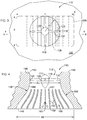
FIG. 1 is a schematic top plan view of an exemplary lift fan; -
FIG. 2 is a cross-sectional view taken along lines 2-2 ofFIG. 1 ; -
FIG. 3 is a schematic top plan view of an alternative lift fan; -
FIG. 4 is a cross-sectional view taken along lines 4-4 ofFIG. 3 ; -
FIG. 5 is a schematic top plan view of an alternative lift fan; -
FIG. 6 is a cross-sectional view taken along lines 6-6 ofFIG. 5 ; -
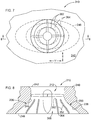
FIG. 7 is a schematic top land view of an alternative lift fan; and -
FIG. 8 is a cross-sectional view taken along lines 8-8 ofFIG. 7 . - Referring to the drawings wherein identical reference numerals denote the same elements throughout the various views,
FIG. 1 depicts anexemplary lift fan 10. As used herein, the term "lift fan" refers to a thrust-producing structure which is suitable for providing direct lift of the vehicle or similar purposes. This may alternatively be referred to herein as a "hover fan". It will be understood that the principles described herein are equally applicable to fans which merely provide supplemental lift or maneuvering control, as well as fans capable of providing sufficient thrust to allow a vehicle to hover and/or climb. In the illustrated example, thelift fan 10 includes asingle rotor 12. - The
rotor 12 is drivingly coupled to aprime mover 14 which may be any device operable to rotate therotor 12 at the required speed under expected mechanical and aerodynamic loads. Nonlimiting examples of prime movers include heat engines, motors (e.g. electric, hydraulic, or pneumatic), or combinations thereof (for example electric hybrid drivetrains). In one example, theprime mover 14 may comprise a gas turbine engine including, in axial flow sequence, a compressor, a combustor, and one or more turbines. Therotor 12 may be driven directly by theprime mover 14, or through an intermediate means such as a geartrain, or by bleed air from a prime mover (e.g. using a tip turbine). - The
rotor 12 comprises a hub ordisk 16 having a plurality ofblades 18 extending therefrom. Eachblade 18 extends from aroot 20 at thehub 16 to atip 22 and includes a generally concave pressure side joined to a generally convex suction side at a leadingedge 28 and atrailing edge 30. Eachblade 18 has a span (or span dimension) defined as the radial distance from theroot 20 to thetip 22, and every airfoil section thereof has a chord (or chord dimension) defined as the length of an imaginary straight line, referred to as a "chord line", connecting theleading edge 28 and thetrailing edge 30. Theblades 18 can be uniformly or non-uniformly spaced apart around the periphery of thehub 16. The illustrated example shows asingle rotor 12. Optionally, thelift fan 10 could include features such as multiple rotor stages (either co-rotating or counter-rotating) and/or stationary stator airfoils, positioned upstream and/or downstream of the rotatingblades 18. - In operation, the
hub 16 rotates about acentral axis 32, and theblades 18 sweep through arotor plane 34 which is perpendicular to thecentral axis 32. Airfoil sections of theblades 18 are each disposed at some pitch angle, dependent on radius (theblades 18 may incorporate twist) and measured between the blade's chord line and therotor plane 34. Theblades 18 may have a "fixed pitch" configuration in which the airfoil section pitch angles of theblades 18 cannot be changed. Alternatively, theblades 18 may have a "variable pitch" configuration in which the airfoil section pitch angles of theblades 18 may be uniformly varied (i.e. same pitch angle change for all airfoil sections) in flight. A variable-pitch rotor may be used to provide thrust efficiently in varying flight conditions. One or more conventional pitch change actuators (not shown) may be used to effect pitch changes. - The rotor is disposed in a
duct 36, bounded by peripheral wall surfaces 38. The peripheral wall surfaces 38 are part of avehicle structure 40 which is shown in fragmentary view inFIG. 2 . In the illustrated example, the peripheral wall surfaces 38 are a body of revolution and may alternately be described as a single annular peripheral wall. - The
duct 36 includes, in downstream flow sequence, aninlet 42, a mid-section 44, and anexit 46. - The
inlet 42 is configured (i.e. shaped and sized) to introduce airflow into theduct 36 with minimal pressure loss and flow disturbance. In the illustrated example, the inlet includes a convex-radiused lip 48 for the purpose of enhancing flow turning into theduct 36. - The
rotor 12 is positioned within the mid-section 44. The mid-section 44 has a shape which closely surrounds thetips 22 of theblades 18 to minimize flow leakage. The mid-section 44 may be of constant area or may have an area which increases or decreases from its upstream end to its downstream end. The mid-section 44 may have a shape which is curved or otherwise contoured to closely conform to theblade tips 22. Optionally, the mid-section 44 may include a sacrificial or abradable element (not shown) to accommodate "rubs" or other minor contact of theblade tips 22. - The
duct 36 incorporates adiffuser 50 positioned downstream of therotor 12. In the illustrated example, theduct 36 has a flow area "A1" measured within the mid-section 44 immediately downstream of therotor 12, and a flow area "A2" measured at theexit 46. For reference purposes, the flow area A1 may be described as the flow area "at the rotor". The flow area A2 is greater than the flow area A1, thus defining thediffuser 50. The ratio of the flow areas A2/A1 ("diffusion ratio") and the axial or streamwise rate of change between the two, that is, the profile shape of the peripheral wall surfaces ("diffusion rate"), may be selected to suit a specific application. In one example, the flow area A2 could be at least 50% greater than the flow area A1. In another example, the flow area A2 could be at least 100% greater than the flow area A1. In the illustrated example, theduct 36 is axisymmetrical about thecentral axis 32. However, it will be understood that theduct 36 could be asymmetrical, or it could be symmetrical about an arbitrary plane, or an axis other than thecentral axis 32. - Is generally desirable to make an overall flow length "L" of the
duct 36 measured from theinlet 42 to theexit 46 as short as possible, for the purpose of overall compactness and ease of incorporation into thevehicle structure 40. However, a large rate of change in the area over a short length of a duct can cause problems such as flow separation. It has been discovered that the overall length L can be made shorter than would otherwise be required, while avoiding flow separation, by the incorporation of splitters into thediffuser 50. - In the illustrated example, a plurality of spaced-
apart splitters 52 are disposed in theduct 36. Each of thesplitters 52 has opposed side walls extending between aleading edge 56 and a trailingedge 58. Thesplitters 52 subdivide theduct 36 into a plurality of generallyparallel flow passages 60. Thesplitters 52 may be annular structures configured as concentric rings as shown, or could extend along a straight line, or follow some curvilinear shape. In the illustrated example, thesplitters 52 would be provided with some exterior support (not shown) such as struts or brackets connecting them to the peripheral wall 38. Alternatively, thesplitters 52 could derive structural support by extending all the way to the peripheral wall 38. - Each of the
flow passages 60 has a flow area at its upstream end, designated "A3", and a flow area at theexit 46, designated "A4". Thesplitters 52 are configured such that eachflow passage 60 acts as a diffuser, or stated another way, the flow area A4 is greater than the flow area A3. - The
flow passages 60 may be configured so as to have similar or equal diffusion ratios, or stated another way, for the ratio A4/A3 to be approximately equal for eachflow passage 60. It is also beneficial for reducing flow losses if theflow passages 60 are configured so as to have similar or equal diffusion rates as defined above. - The
splitters 52 are shaped and sized so as to act as turning vanes, that is to turn the flow of the first fluid in an axial-radial plane in a manner so as to prevent flow separation from the peripheral wall surfaces 38. The specific degree of flow turning will depend upon the shape of the mean line of the splitters and their angle of attack relative to the fluid flow. -
FIGS. 3 and 4 illustrate analternative lift fan 110 which is similar in general construction to thelift fan 10 described above. Elements of thelift fan 110 not specifically described may be considered to be identical to corresponding elements of thelift fan 10. Thelift fan 110 includes arotor 112 connected to aprime mover 114. Therotor 112 includes a hub ordisk 116 having a plurality ofblades 118 extending therefrom. Eachblade 118 extends from aroot 120 at thehub 116 to atip 122 and includes opposed pressure and suction sides extending between aleading edge 128 and a trailingedge 130. Theblades 118 may be fixed pitch or variable pitch. - The
rotor 112 is disposed in aduct 136, bounded by peripheral wall surfaces 138. The peripheral wall surfaces 138 are part of avehicle structure 140 which is shown in fragmentary view inFIG. 4 . Theduct 136 includes, in downstream flow sequence, aninlet 142, a mid-section 144, and anexit 146. - The
inlet 142 is configured (i.e. shaped and sized) to introduce airflow into theduct 136 with minimal pressure loss in flow disturbance. In the illustrated example, the inlet includes a convex-radiusedlip 148 for the purpose of enhancing flow turning into theduct 136. - The
rotor 112 is positioned within themid-section 144. The mid-section 144 has a shape which closely surrounds thetips 122 of theblades 118 to minimize flow leakage. In this example the mid-section 144 is a body of revolution. The mid-section 144 may be of constant flow area or may have a flow area which increases or decreases from its upstream end to its downstream end. The mid-section 144 may have a shape which is curved or otherwise contoured to closely conform to theblade tips 122 Optionally, the mid-section 144 may include a sacrificial or abradable element (not shown) to accommodate "rubs" or other minor contact of theblade tips 122. - The
duct 136 incorporates adiffuser 150 positioned downstream of therotor 112. Thediffuser 150 has a flow area "A5" measured within the mid-section 144 immediately downstream of therotor 112, and a flow area "A6" measured at theexit 146. For reference purposes, the flow area A5 may be described as the flow area "at the rotor". The diffuser ratio A6/A5 and the diffusion rate may be selected to suit a specific application. In one example, the flow area A6 could be at least 50% greater than the flow area A5. In another example, the flow area A6 could be at least 100% greater than the flow area A5. - In this embodiment, the
diffuser 150 has a circular plan view (i.e., flow area) shape at an upstream end where it adjoins the mid-section 144, and transitions to a generally rectangular plan view (i.e., flow area) shape with radiused corners at theexit 146. The generally rectangular shape is an example of an elongated, non-axisymmetric shape. The generally rectangular shape at theexit 146 has a characteristic overall width dimension "X" and a characteristic overall length dimension "Y" measured perpendicular to the width dimension X. The width dimension X is approximately equal to a radius "R1" of the mid-section 144 (seeFIG. 3 ). Given equal exit flow areas betweenducts exit 46 of the embodiment shown inFIG. 2 . The length dimension Y is greater than the width dimension X. This rectangular configuration provides at least one dimension which is more compact than that of thelift fan 10 shown inFIGS. 1 and 2 . This may be useful for the purpose of placing two ormore lift fans 110 next to each other in close proximity while minimizing the space used within a vehicle structure. - Optionally, the
duct 136 may incorporate splitters. In the example shown inFIG. 4 , a plurality of spaced-apart splitters 152 are disposed in theduct 136. Each of thesplitters 152 has opposed side walls extending between aleading edge 162 and a trailingedge 164. Thesplitters 152 subdivide theduct 36 into a plurality of generallyparallel flow passages 166. In the illustrated example, thesplitters 152 extend between opposed peripheral wall surfaces 138 parallel to the dimension Y described above; however, other shapes could be used. - The
splitters 152 are configured such that eachflow passage 166 acts as a diffuser. Theflow passages 166 may be configured so as to have similar or equal diffusion ratios. Theflow passages 166 may be configured so as to have similar or equal diffusion rates as defined above. - Optionally, all or a portion of the
splitters 152 may be moveable. The moveable splitters or portions may be used for functions such as flow throttling or thrust vectoring. In the example shown inFIG. 4 , one of thesplitters 152 is shown with apivotable flap 153 disposed adjacent the trailingedge 164. Theflap 153 or other moveable component may be operated by conventional actuators (not shown). - Many shape variations are possible for the lift fan ducts.
FIGS. 5-8 illustrate embodiments in which the duct has a circular inlet and an elliptical exit, with different configurations of splitters.FIGS. 5 and 6 illustrate analternative lift fan 210 which is similar in general construction to thelift fan 10 described above. Elements of thelift fan 210 not specifically described may be considered to be identical to corresponding elements of thelift fan 10. Thelift fan 210 includes arotor 212 connected to aprime mover 214. Therotor 212 includes a hub ordisk 216 having a plurality ofblades 218 extending therefrom. Eachblade 218 extends from aroot 220 at thehub 216 to a tip 222 and includes opposed pressure and suction sides extending between aleading edge 228 and a trailingedge 230. Theblades 218 may be fixed pitch or variable pitch. - The
rotor 212 is disposed in aduct 236, bounded by peripheral wall surfaces 238. The peripheral wall surfaces 238 are part of avehicle structure 240 which is shown in fragmentary view inFIG. 6 . Theduct 236 includes, in downstream flow sequence, aninlet 242, a mid-section 244, and anexit 246. - The
inlet 242 is configured to introduce airflow into theduct 236 with minimal pressure loss in flow disturbance. In the illustrated example, the inlet includes a convex-radiusedlip 248 for the purpose of enhancing flow turning into theduct 236. - The
rotor 212 is positioned within themid-section 244. The mid-section 244 has a shape which closely surrounds the tips 222 of theblades 218 to minimize flow leakage. In this example the mid-section 244 is a body of revolution. The mid-section 144 may be of constant flow area or may have a flow area which increases or decreases from its upstream end to its downstream end. The mid-section 244 may have a shape which is curved or otherwise contoured to closely conform to the blade tips 222. Optionally, the mid-section 244 may include a sacrificial or abradable element (not shown) to accommodate "rubs" or other minor contact of the blade tips 222. - The
duct 236 incorporates adiffuser 250 positioned downstream of therotor 212. Thediffuser 250 has a flow area "A7" measured within the mid-section 244 immediately downstream of therotor 212, and a flow area "A8" measured at theexit 246. For reference purposes, the flow area A7 may be described as the flow area "at the rotor". The diffusion ratio of the flow areas A8/A7 and the diffusion rate may be selected to suit a specific application. In one example, the flow area A8 could be at least 50% greater than the flow area A7. In another example, the flow area A8 could be at least 100% greater than the flow area A7. - In this embodiment, the
diffuser 250 has a circular plan view (i.e., flow area) shape at an upstream end where it adjoins the mid-section 244, and transitions at theexit 246 to a plan view (i.e., flow area) shape which is an elongated, non-axisymmetric shape. In this example the shape is an ellipse. - Optionally, the
duct 236 may incorporate splitters. In the example shown inFIG. 6 , a plurality of spaced-apart splitters 252 are disposed in theduct 236. Each of thesplitters 252 has opposed side walls extending between aleading edge 262 and a trailingedge 264. Thesplitters 252 are generally annular and subdivide theduct 236 into a plurality of generally parallel, generallyannular flow passages 266. Thesplitters 252 may smoothly transition or "morph" from one shape to another. In the illustrated example, one or more of theindividual splitters 252 has a shape which transitions or morphs from an ellipse with a first orientation having a longer dimension (i.e. major axis) parallel to a first direction "X" at theleading edge 262, to an ellipse with a second orientation having a longer dimension (i.e. major axis) parallel to a second direction "Y" at the trailingedge 264. For simplicity of illustration, only the leading and trailingedges splitters 252 are depicted inFIG. 5 . - The
splitters 252 are configured such that eachflow passage 266 acts as a diffuser. Theflow passages 266 may be configured so as to have similar or equal diffusion ratios. Theflow passages 266 may be configured so as to have similar or equal diffusion rates as defined above. -
FIGS. 7 and 8 depict analternative lift fan 310 which is a variation of thelift fan 210 shown inFIGS. 5 and 6 and has anidentical rotor 212 andduct 236, with peripheral wall surfaces 238 defining aninlet 242, a mid-section 244, and anexit 246, and adiffuser 250. - The
duct 236 incorporatessplitters 352 in thediffuser 250. Each of thesplitters 352 has opposed side walls extending between aleading edge 362 and a trailingedge 364. Thesplitters 352 are generally annular and subdivide theduct 236 into a plurality of generally parallel, generallyannular flow passages 366. In the illustrated example, one or more of theindividual splitters 352 has an elliptical shape which transitions or "morphs" from a circular shape at theleading edge 362, to an elliptical or otherwise elongated shape having a longer dimension (i.e. major axis) parallel to a direction "Y" at the trailingedge 364. For simplicity of illustration, only the leading and trailing edges of thesplitters 352 are depicted inFIG. 7 . - The
splitters 362 are configured such that eachflow passage 366 acts as a diffuser. Theflow passages 366 may be configured so as to have similar or equal diffusion ratios. Theflo w passages 366 may be configured so as to have similar or equal diffusion rates as defined above. - The apparatus described herein has several advantages over the prior art. The presence of the diffuser downstream of a lift fan rotor allows for more air (i.e. mass/volume flow) to be drawn through a given fan diameter and hence the hover efficiency increased.
- The flow length of the diffuser can be significantly shortened by adding splitters and this can also reduce surface friction losses. The splitters can help unload the outer duct wall and move the aerodynamic loading to the vanes that can operate in cleaner air.
- The foregoing has described a lift fan. All of the features disclosed in this specification (including any accompanying claims, abstract and drawings), and/or all of the steps of any method or process so disclosed, may be combined in any combination, except combinations where at least some of such features and/or steps are mutually exclusive.
- Each feature disclosed in this specification (including any accompanying claims, abstract and drawings) may be replaced by alternative features serving the same, equivalent or similar purpose, unless expressly stated otherwise. Thus, unless expressly stated otherwise, each feature disclosed is one example only of a generic series of equivalent or similar features.
- The invention is not restricted to the details of the foregoing embodiment(s). The invention extends to any novel one, or any novel combination, of the features disclosed in this specification (including any accompanying claims, abstract and drawings), or to any novel one, or any novel combination, of the steps of any method or process so disclosed.
- Further aspects of the invention are provided by the subject-matter of the following numbered clauses:
- 1. A lift fan apparatus, comprising:
- a rotor having at least one rotatable hub carrying at least one row of blades;
- a duct surrounding the rotor, the duct including spaced-apart peripheral walls extending between an inlet and an exit, the peripheral walls collectively defining a flow channel which includes a diffuser disposed downstream of the rotor, in which a flow area at the exit is greater than a flow area at the rotor; and
- a plurality of spaced-apart splitters disposed in the diffuser, each of the splitters having opposed side walls extending between an upstream leading edge and a downstream trailing edge, wherein the splitters divide the diffuser into a plurality of side-by-side flow passages.
- 2. The apparatus of clause 1 wherein a flow area of each of the flow passages increases in a downstream direction.
- 3. The apparatus of any preceding clause wherein the flow passages have equal diffusion ratios.
- 4. The apparatus of any preceding clause wherein the splitters are configured to turn a flow passing through the duct in at least one plane.
- 5. The apparatus of any preceding clause wherein a flow area of the duct at the exit is at least 50% greater than a flow area of the duct at the rotor.
- 6. The apparatus of any preceding clause wherein a flow area of the duct at the exit is at least 100% greater than a flow area of the duct at the rotor.
- 7. The apparatus of any preceding clause further comprising a prime mover coupled in driving relationship with the hub.
- 8. The apparatus of any preceding clause wherein the duct includes a mid-section disposed between the inlet and the diffuser, the mid-section being a body of revolution.
- 9. The apparatus of any preceding clause wherein the diffuser includes an upstream portion with a first flow area shape and a downstream portion which has a second flow area shape different from the first flow area shape.
- 10. The apparatus of any preceding clause wherein the first flow area shape which is a body of revolution and a downstream portion which has an elongated non-axisymmetric flow area shape.
- 11. The apparatus of any preceding clause wherein the downstream portion has a width dimension which is equal to a radius of the upstream portion, and a length dimension measured perpendicular to the width dimension, wherein the length dimension which is greater than the width dimension.
- 12. The apparatus of any preceding clause wherein at least one of the splitters has a first flow area shape at its leading edge and transitions to a second flow area shape at its trailing edge, wherein the second flow area shape is different from the first flow area shape.
- 13. The apparatus of any preceding clause wherein at least a portion of at least one of the splitters is moveable.
- 14. A lift fan apparatus, comprising:
- a vehicle structure;
- a duct disposed in the vehicle structure, the duct including spaced-apart peripheral walls extending between an inlet and an exit, the peripheral walls collectively defining a flow channel which includes a diffuser communicating with the exit;
- a rotor mounted in the duct upstream of the diffuser, the rotor having at least one rotatable hub carrying at least one row of blades;
- a prime mover coupled in driving relationship with the hub; and
- a plurality of spaced-apart splitters disposed in the diffuser, each of the splitters having opposed side walls extending between an upstream leading edge and a downstream trailing edge, wherein the splitters divide the diffuser into a plurality of side-by-side flow passages.
- 15. The apparatus of
clause 14 wherein a flow area of each of the flow passages increases in a downstream direction. - 16. The apparatus of
clause 14 or 15 wherein the flow passages have equal diffusion ratios. - 17. The apparatus of any of
clauses 14 to 16 wherein a flow area of the duct at the exit is at least 50% greater than a flow area of the duct at the rotor. - 18. The apparatus of any of
clauses 14 to 17 wherein the duct includes a mid-section disposed between the inlet and the diffuser, the mid-section being a body of revolution. - 19. The apparatus of any preceding clause wherein the diffuser includes an upstream portion with a first flow area shape and a downstream portion which has a second flow area shape different from the first flow area shape.
- 20. The apparatus of any preceding clause wherein at least one of the splitters has a first flow area shape at its leading edge and transitions to a second flow area shape at its trailing edge, wherein the second flow area shape is different from the first flow area shape.
Claims (15)
- A lift fan apparatus (10, 110, 210, 310), comprising:a rotor (12, 112, 212) having at least one rotatable hub carrying at least one row of blades;a duct (36, 136, 236) surrounding the rotor (12, 112, 212), the duct (36, 136, 236) including spaced-apart peripheral walls extending between an inlet and an exit, the peripheral walls collectively defining a flow channel which includes a diffuser (50, 150, 250) disposed downstream of the rotor (12, 112, 212), in which a flow area at the exit is greater than a flow area at the rotor (12, 112, 212); anda plurality of spaced-apart splitters disposed in the diffuser (50, 150, 250), each of the splitters having opposed side walls extending between an upstream leading edge and a downstream trailing edge, wherein the splitters divide the diffuser (50, 150, 250) into a plurality of side-by-side flow passages (66, 166, 266, 366).
- The apparatus (10, 110, 210, 310) of claim 1 wherein a flow area of each of the flow passages (66, 166, 266, 366) increases in a downstream direction.
- The apparatus (10, 110, 210, 310) of claim 1 or 2 wherein the flow passages (66, 166, 266, 366) have equal diffusion ratios.
- The apparatus (10, 110, 210, 310) of any of claims 1 to 3 wherein the splitters are configured to turn a flow passing through the duct (36, 136, 236) in at least one plane.
- The apparatus (10, 110, 210, 310) of any of claims 1 to 4 wherein a flow area of the duct (36, 136, 236) at the exit is at least 50% greater than a flow area of the duct (36, 136, 236) at the rotor (12, 112, 212).
- The apparatus (10, 110, 210, 310) of any of claims 1 to 5 wherein a flow area of the duct (36, 136, 236) at the exit is at least 100% greater than a flow area of the duct (36, 136, 236) at the rotor (12, 112, 212).
- The apparatus (10, 110, 210, 310) of any of claims 1 to 6 further comprising a prime mover coupled in driving relationship with the hub.
- The apparatus (10, 110, 210, 310) of any of claims 1 to 7 wherein the duct (36, 136, 236) includes a mid-section disposed between the inlet and the diffuser (50, 150, 250), the mid-section being a body of revolution.
- The apparatus (10, 110, 210, 310) of any of claims 1 to 8 wherein the diffuser (50, 150, 250) includes an upstream portion with a first flow area shape and a downstream portion which has a second flow area shape different from the first flow area shape.
- The apparatus (10, 110, 210, 310) of claim 9 wherein the first flow area shape which is a body of revolution and a downstream portion which has an elongated non-axisymmetric flow area shape.
- The apparatus (10, 110, 210, 310) of claim 9 or 10 wherein the downstream portion has a width dimension which is equal to a radius of the upstream portion, and a length dimension measured perpendicular to the width dimension, wherein the length dimension which is greater than the width dimension.
- The apparatus (10, 110, 210, 310) of any of claims 1 to 11 wherein at least one of the splitters has a first flow area shape at its leading edge and transitions to a second flow area shape at its trailing edge, wherein the second flow area shape is different from the first flow area shape.
- The apparatus (10, 110, 210, 310) of any of claims 1 to 12 wherein at least a portion of at least one of the splitters is moveable.
- A lift fan apparatus (10, 110, 210, 310), comprising:a vehicle structure including the lift fan apparatus (10, 110, 210, 310) of claim 1; anda prime mover coupled in driving relationship with the hub of the lift fan apparatus (10, 110, 210, 310).
- The apparatus (10, 110, 210, 310) of claim 14 wherein the diffuser (50, 150, 250) includes an upstream portion with a first flow area shape and a downstream portion which has a second flow area shape different from the first flow area shape.
Applications Claiming Priority (1)
| Application Number | Priority Date | Filing Date | Title |
|---|---|---|---|
| US16/042,141 US11352132B2 (en) | 2018-07-23 | 2018-07-23 | Lift fan with diffuser duct |
Publications (2)
| Publication Number | Publication Date |
|---|---|
| EP3599159A1 true EP3599159A1 (en) | 2020-01-29 |
| EP3599159B1 EP3599159B1 (en) | 2024-07-10 |
Family
ID=67438519
Family Applications (1)
| Application Number | Title | Priority Date | Filing Date |
|---|---|---|---|
| EP19187775.2A Active EP3599159B1 (en) | 2018-07-23 | 2019-07-23 | Lift fan with diffuser duct |
Country Status (3)
| Country | Link |
|---|---|
| US (1) | US11352132B2 (en) |
| EP (1) | EP3599159B1 (en) |
| CN (1) | CN110745237B (en) |
Cited By (1)
| Publication number | Priority date | Publication date | Assignee | Title |
|---|---|---|---|---|
| EP3875369A4 (en) * | 2018-12-13 | 2021-12-29 | Mitsubishi Heavy Industries, Ltd. | Motor-integrated fluid machine and vertical take-off and landing aircraft |
Families Citing this family (7)
| Publication number | Priority date | Publication date | Assignee | Title |
|---|---|---|---|---|
| US10822101B2 (en) * | 2017-07-21 | 2020-11-03 | General Electric Company | Vertical takeoff and landing aircraft having a forward thrust propulsor |
| US12071228B1 (en) * | 2019-03-28 | 2024-08-27 | Snap Inc. | Drone with propeller guard configured as an airfoil |
| WO2021076250A2 (en) * | 2019-09-11 | 2021-04-22 | Alexandru Balan | 360° advanced rotation system |
| US11899470B2 (en) * | 2020-01-30 | 2024-02-13 | Disney Enterprises, Inc. | Airframe of a volitant body |
| EP4015362B1 (en) * | 2020-12-18 | 2024-10-09 | Aurora Flight Sciences Corporation, a subsidiary of The Boeing Company | Fan apparatus with lift fan and louvered cover |
| DE102021201115A1 (en) * | 2021-02-05 | 2022-08-11 | Rolls-Royce Solutions GmbH | Manifold, turbomachine with such a manifold, exhaust gas turbocharger with such a turbomachine, and internal combustion engine with such a manifold |
| GB202308303D0 (en) * | 2023-06-02 | 2023-07-19 | Cambridge Entpr Ltd | Fan and fan assembly |
Citations (3)
| Publication number | Priority date | Publication date | Assignee | Title |
|---|---|---|---|---|
| US2929580A (en) * | 1956-06-18 | 1960-03-22 | Piasecki Aircraft Corp | Aircraft for vertical or short takeoff, and integrated propulsion lifting and propeller slip stream deflecting unit therefor |
| FR73117E (en) * | 1958-01-02 | 1960-09-23 | R L Cie De Rech S Et D Etudes | Improvements to air navigation devices |
| US5035377A (en) * | 1985-02-28 | 1991-07-30 | Technolizenz Establishment | Free standing or aircraft lift generator |
Family Cites Families (34)
| Publication number | Priority date | Publication date | Assignee | Title |
|---|---|---|---|---|
| US2330907A (en) * | 1938-09-10 | 1943-10-05 | J H Everest | Aerodynamic device |
| US2953320A (en) * | 1955-07-18 | 1960-09-20 | Charles B Bolton | Aircraft with ducted lifting fan |
| NL110393C (en) * | 1955-11-29 | 1965-01-15 | Bertin & Cie | |
| US3054578A (en) * | 1957-10-08 | 1962-09-18 | Cie De Rech S Et D Etudes Aero | Annular aircraft with elastic collector ring rim |
| GB851273A (en) * | 1958-04-23 | 1960-10-12 | Power Jets Res & Dev Ltd | Aircraft air intakes |
| US3045947A (en) * | 1959-04-24 | 1962-07-24 | Bertin & Cie | Ejectors, particularly for producing lift in aircraft |
| FR1254416A (en) * | 1959-10-16 | 1961-02-24 | Bertin & Cie | Diffuser for fluid and devices including application |
| US3013744A (en) | 1960-03-11 | 1961-12-19 | Gen Electric | Vtol boundary layer control system |
| US3170530A (en) | 1961-03-23 | 1965-02-23 | Richard W Black | Mobile air supported vehicle |
| CA981918A (en) * | 1972-11-30 | 1976-01-20 | Lester W. Throndson | Compound ejector for high energy flow fluid |
| US3819134A (en) | 1972-11-30 | 1974-06-25 | Rockwell International Corp | Aircraft system lift ejector |
| US3846039A (en) * | 1973-10-23 | 1974-11-05 | Stalker Corp | Axial flow compressor |
| US4075500A (en) * | 1975-08-13 | 1978-02-21 | Grumman Aerospace Corporation | Variable stator, diffuser augmented wind turbine electrical generation system |
| US4815942A (en) | 1982-10-25 | 1989-03-28 | Elayne P. Alperin | Axially-symmetric, jet-diffuser ejector |
| ZA839309B (en) * | 1983-06-06 | 1985-09-14 | ||
| US4796836A (en) | 1985-02-28 | 1989-01-10 | Dieter Schatzmayr | Lifting engine for VTOL aircrafts |
| BR9106696A (en) | 1990-07-25 | 1993-06-08 | Sadleir Vtol Aircraft Co Pty L | FLUSHING UNIT FOR VTOL AIRCRAFT |
| US5077967A (en) * | 1990-11-09 | 1992-01-07 | General Electric Company | Profile matched diffuser |
| FR2711771B1 (en) * | 1993-10-27 | 1995-12-01 | Snecma | Variable circumferential feed chamber diffuser. |
| WO2002103209A1 (en) * | 2001-06-15 | 2002-12-27 | Concepts Eti, Inc. | Flow stabilizing device |
| US7032861B2 (en) | 2002-01-07 | 2006-04-25 | Sanders Jr John K | Quiet vertical takeoff and landing aircraft using ducted, magnetic induction air-impeller rotors |
| DE102004036331A1 (en) * | 2004-07-27 | 2006-02-16 | Man Turbo Ag | Inflow housing for axial flow machines |
| US8336806B2 (en) * | 2008-12-30 | 2012-12-25 | Rolls-Royce North American Technologies, Inc. | Lift fan flow path device |
| US20110274533A1 (en) * | 2010-05-07 | 2011-11-10 | Flodesign Wind Turbine Corp. | Fluid turbine with moveable fluid control member |
| WO2011151323A2 (en) * | 2010-06-01 | 2011-12-08 | Esg Mbh | Duct having a flow-guiding surface |
| DE202010016820U1 (en) * | 2010-12-21 | 2012-03-26 | Ebm-Papst Mulfingen Gmbh & Co. Kg | Diffuser for a fan and fan assembly with such a diffuser |
| DE102012003336A1 (en) * | 2012-02-17 | 2013-08-22 | Ziehl-Abegg Ag | Diffuser, fan with such a diffuser and device with such fans |
| EP2712805B1 (en) | 2012-09-28 | 2016-03-02 | AGUSTAWESTLAND S.p.A. | System and method for cooling a hover-capable aircraft transmission |
| EP2738091B1 (en) | 2012-11-30 | 2015-07-22 | AIRBUS HELICOPTERS DEUTSCHLAND GmbH | Vertical take-off and landing (VTOL) aerial vehicle and method of operating such a VTOL aerial vehicle |
| FR3008383B1 (en) | 2013-07-12 | 2017-11-24 | Hutchinson | AXIS (S) BLOWING SUSPENDING DEVICE, AND AERODYNE EQUIPPED WITH SUCH A DEVICE |
| US9945391B2 (en) * | 2014-03-27 | 2018-04-17 | Trane International Inc. | Diffuser collar |
| US10221861B2 (en) * | 2014-06-06 | 2019-03-05 | Airius Ip Holdings Llc | Columnar air moving devices, systems and methods |
| US10570925B2 (en) * | 2015-10-27 | 2020-02-25 | Pratt & Whitney Canada Corp. | Diffuser pipe with splitter vane |
| US10822101B2 (en) * | 2017-07-21 | 2020-11-03 | General Electric Company | Vertical takeoff and landing aircraft having a forward thrust propulsor |
-
2018
- 2018-07-23 US US16/042,141 patent/US11352132B2/en active Active
-
2019
- 2019-07-23 CN CN201910666697.9A patent/CN110745237B/en active Active
- 2019-07-23 EP EP19187775.2A patent/EP3599159B1/en active Active
Patent Citations (3)
| Publication number | Priority date | Publication date | Assignee | Title |
|---|---|---|---|---|
| US2929580A (en) * | 1956-06-18 | 1960-03-22 | Piasecki Aircraft Corp | Aircraft for vertical or short takeoff, and integrated propulsion lifting and propeller slip stream deflecting unit therefor |
| FR73117E (en) * | 1958-01-02 | 1960-09-23 | R L Cie De Rech S Et D Etudes | Improvements to air navigation devices |
| US5035377A (en) * | 1985-02-28 | 1991-07-30 | Technolizenz Establishment | Free standing or aircraft lift generator |
Cited By (2)
| Publication number | Priority date | Publication date | Assignee | Title |
|---|---|---|---|---|
| EP3875369A4 (en) * | 2018-12-13 | 2021-12-29 | Mitsubishi Heavy Industries, Ltd. | Motor-integrated fluid machine and vertical take-off and landing aircraft |
| US12246842B2 (en) | 2018-12-13 | 2025-03-11 | Mitsubishi Heavy Industries, Ltd. | Motor-integrated fluid machine and vertical take-off and landing aircraft |
Also Published As
| Publication number | Publication date |
|---|---|
| US20200023959A1 (en) | 2020-01-23 |
| CN110745237B (en) | 2023-04-07 |
| US11352132B2 (en) | 2022-06-07 |
| CN110745237A (en) | 2020-02-04 |
| EP3599159B1 (en) | 2024-07-10 |
Similar Documents
| Publication | Publication Date | Title |
|---|---|---|
| EP3599159B1 (en) | Lift fan with diffuser duct | |
| US20200271010A1 (en) | Unducted thrust producing system | |
| US11401824B2 (en) | Gas turbine engine outlet guide vane assembly | |
| US11300003B2 (en) | Unducted thrust producing system | |
| CA3013156C (en) | Low-noise airfoil for an open rotor | |
| US11608743B1 (en) | Low-noise blade for an open rotor | |
| US20210108523A1 (en) | Unducted single rotor engine | |
| CN109131832B (en) | Open rotor and airfoil thereof | |
| US12140040B2 (en) | Airfoil assembly with a differentially oriented stage | |
| US12492642B2 (en) | Outlet guide vane assembly for a turbofan engine | |
| US12049306B2 (en) | Low-noise blade for an open rotor | |
| CN111075760A (en) | Fluid wing | |
| US20230167783A1 (en) | Propulsion system for a gas turbine engine | |
| US12276199B2 (en) | Outlet guide vane assembly for a turbofan engine | |
| CN117769516A (en) | aviation propeller | |
| US20260084826A1 (en) | Aircraft with an unducted fan propulsor | |
| US20260103278A1 (en) | Aircraft with an unducted fan propulsor | |
| US20250223909A1 (en) | Outlet guide vane assembly for a turbofan engine | |
| US20260035081A1 (en) | Aircraft with an unducted fan propulsor | |
| US20250270937A1 (en) | Vane Assembly For Open Fan Engine | |
| CN119222002A (en) | Ductless airfoil assembly | |
| CN116557346A (en) | Airfoil assembly with different orientation stages | |
| JP3270845B2 (en) | Boundary layer control mechanism for short take-off and landing aircraft and its compressor | |
| CN118728492A (en) | Ductless airfoil assembly |
Legal Events
| Date | Code | Title | Description |
|---|---|---|---|
| PUAI | Public reference made under article 153(3) epc to a published international application that has entered the european phase |
Free format text: ORIGINAL CODE: 0009012 |
|
| STAA | Information on the status of an ep patent application or granted ep patent |
Free format text: STATUS: THE APPLICATION HAS BEEN PUBLISHED |
|
| AK | Designated contracting states |
Kind code of ref document: A1 Designated state(s): AL AT BE BG CH CY CZ DE DK EE ES FI FR GB GR HR HU IE IS IT LI LT LU LV MC MK MT NL NO PL PT RO RS SE SI SK SM TR |
|
| AX | Request for extension of the european patent |
Extension state: BA ME |
|
| STAA | Information on the status of an ep patent application or granted ep patent |
Free format text: STATUS: REQUEST FOR EXAMINATION WAS MADE |
|
| 17P | Request for examination filed |
Effective date: 20200729 |
|
| RBV | Designated contracting states (corrected) |
Designated state(s): AL AT BE BG CH CY CZ DE DK EE ES FI FR GB GR HR HU IE IS IT LI LT LU LV MC MK MT NL NO PL PT RO RS SE SI SK SM TR |
|
| STAA | Information on the status of an ep patent application or granted ep patent |
Free format text: STATUS: EXAMINATION IS IN PROGRESS |
|
| 17Q | First examination report despatched |
Effective date: 20211019 |
|
| GRAP | Despatch of communication of intention to grant a patent |
Free format text: ORIGINAL CODE: EPIDOSNIGR1 |
|
| STAA | Information on the status of an ep patent application or granted ep patent |
Free format text: STATUS: GRANT OF PATENT IS INTENDED |
|
| INTG | Intention to grant announced |
Effective date: 20240205 |
|
| GRAS | Grant fee paid |
Free format text: ORIGINAL CODE: EPIDOSNIGR3 |
|
| GRAA | (expected) grant |
Free format text: ORIGINAL CODE: 0009210 |
|
| STAA | Information on the status of an ep patent application or granted ep patent |
Free format text: STATUS: THE PATENT HAS BEEN GRANTED |
|
| AK | Designated contracting states |
Kind code of ref document: B1 Designated state(s): AL AT BE BG CH CY CZ DE DK EE ES FI FR GB GR HR HU IE IS IT LI LT LU LV MC MK MT NL NO PL PT RO RS SE SI SK SM TR |
|
| REG | Reference to a national code |
Ref country code: CH Ref legal event code: EP |
|
| REG | Reference to a national code |
Ref country code: DE Ref legal event code: R096 Ref document number: 602019054887 Country of ref document: DE |
|
| P01 | Opt-out of the competence of the unified patent court (upc) registered |
Free format text: CASE NUMBER: APP_37743/2024 Effective date: 20240625 |
|
| REG | Reference to a national code |
Ref country code: LT Ref legal event code: MG9D |
|
| REG | Reference to a national code |
Ref country code: NL Ref legal event code: MP Effective date: 20240710 |
|
| PG25 | Lapsed in a contracting state [announced via postgrant information from national office to epo] |
Ref country code: PT Free format text: LAPSE BECAUSE OF FAILURE TO SUBMIT A TRANSLATION OF THE DESCRIPTION OR TO PAY THE FEE WITHIN THE PRESCRIBED TIME-LIMIT Effective date: 20241111 |
|
| REG | Reference to a national code |
Ref country code: AT Ref legal event code: MK05 Ref document number: 1701846 Country of ref document: AT Kind code of ref document: T Effective date: 20240710 |
|
| PG25 | Lapsed in a contracting state [announced via postgrant information from national office to epo] |
Ref country code: NL Free format text: LAPSE BECAUSE OF FAILURE TO SUBMIT A TRANSLATION OF THE DESCRIPTION OR TO PAY THE FEE WITHIN THE PRESCRIBED TIME-LIMIT Effective date: 20240710 |
|
| PG25 | Lapsed in a contracting state [announced via postgrant information from national office to epo] |
Ref country code: PT Free format text: LAPSE BECAUSE OF FAILURE TO SUBMIT A TRANSLATION OF THE DESCRIPTION OR TO PAY THE FEE WITHIN THE PRESCRIBED TIME-LIMIT Effective date: 20241111 Ref country code: NL Free format text: LAPSE BECAUSE OF FAILURE TO SUBMIT A TRANSLATION OF THE DESCRIPTION OR TO PAY THE FEE WITHIN THE PRESCRIBED TIME-LIMIT Effective date: 20240710 |
|
| PG25 | Lapsed in a contracting state [announced via postgrant information from national office to epo] |
Ref country code: NO Free format text: LAPSE BECAUSE OF FAILURE TO SUBMIT A TRANSLATION OF THE DESCRIPTION OR TO PAY THE FEE WITHIN THE PRESCRIBED TIME-LIMIT Effective date: 20241010 |
|
| PG25 | Lapsed in a contracting state [announced via postgrant information from national office to epo] |
Ref country code: GR Free format text: LAPSE BECAUSE OF FAILURE TO SUBMIT A TRANSLATION OF THE DESCRIPTION OR TO PAY THE FEE WITHIN THE PRESCRIBED TIME-LIMIT Effective date: 20241011 Ref country code: FI Free format text: LAPSE BECAUSE OF FAILURE TO SUBMIT A TRANSLATION OF THE DESCRIPTION OR TO PAY THE FEE WITHIN THE PRESCRIBED TIME-LIMIT Effective date: 20240710 Ref country code: PL Free format text: LAPSE BECAUSE OF FAILURE TO SUBMIT A TRANSLATION OF THE DESCRIPTION OR TO PAY THE FEE WITHIN THE PRESCRIBED TIME-LIMIT Effective date: 20240710 |
|
| PG25 | Lapsed in a contracting state [announced via postgrant information from national office to epo] |
Ref country code: BG Free format text: LAPSE BECAUSE OF FAILURE TO SUBMIT A TRANSLATION OF THE DESCRIPTION OR TO PAY THE FEE WITHIN THE PRESCRIBED TIME-LIMIT Effective date: 20240710 |
|
| PG25 | Lapsed in a contracting state [announced via postgrant information from national office to epo] |
Ref country code: LV Free format text: LAPSE BECAUSE OF FAILURE TO SUBMIT A TRANSLATION OF THE DESCRIPTION OR TO PAY THE FEE WITHIN THE PRESCRIBED TIME-LIMIT Effective date: 20240710 |
|
| PG25 | Lapsed in a contracting state [announced via postgrant information from national office to epo] |
Ref country code: IS Free format text: LAPSE BECAUSE OF FAILURE TO SUBMIT A TRANSLATION OF THE DESCRIPTION OR TO PAY THE FEE WITHIN THE PRESCRIBED TIME-LIMIT Effective date: 20241110 Ref country code: AT Free format text: LAPSE BECAUSE OF FAILURE TO SUBMIT A TRANSLATION OF THE DESCRIPTION OR TO PAY THE FEE WITHIN THE PRESCRIBED TIME-LIMIT Effective date: 20240710 |
|
| PG25 | Lapsed in a contracting state [announced via postgrant information from national office to epo] |
Ref country code: HR Free format text: LAPSE BECAUSE OF FAILURE TO SUBMIT A TRANSLATION OF THE DESCRIPTION OR TO PAY THE FEE WITHIN THE PRESCRIBED TIME-LIMIT Effective date: 20240710 |
|
| PG25 | Lapsed in a contracting state [announced via postgrant information from national office to epo] |
Ref country code: ES Free format text: LAPSE BECAUSE OF FAILURE TO SUBMIT A TRANSLATION OF THE DESCRIPTION OR TO PAY THE FEE WITHIN THE PRESCRIBED TIME-LIMIT Effective date: 20240710 Ref country code: RS Free format text: LAPSE BECAUSE OF FAILURE TO SUBMIT A TRANSLATION OF THE DESCRIPTION OR TO PAY THE FEE WITHIN THE PRESCRIBED TIME-LIMIT Effective date: 20241010 |
|
| PG25 | Lapsed in a contracting state [announced via postgrant information from national office to epo] |
Ref country code: RS Free format text: LAPSE BECAUSE OF FAILURE TO SUBMIT A TRANSLATION OF THE DESCRIPTION OR TO PAY THE FEE WITHIN THE PRESCRIBED TIME-LIMIT Effective date: 20241010 Ref country code: PL Free format text: LAPSE BECAUSE OF FAILURE TO SUBMIT A TRANSLATION OF THE DESCRIPTION OR TO PAY THE FEE WITHIN THE PRESCRIBED TIME-LIMIT Effective date: 20240710 Ref country code: NO Free format text: LAPSE BECAUSE OF FAILURE TO SUBMIT A TRANSLATION OF THE DESCRIPTION OR TO PAY THE FEE WITHIN THE PRESCRIBED TIME-LIMIT Effective date: 20241010 Ref country code: LV Free format text: LAPSE BECAUSE OF FAILURE TO SUBMIT A TRANSLATION OF THE DESCRIPTION OR TO PAY THE FEE WITHIN THE PRESCRIBED TIME-LIMIT Effective date: 20240710 Ref country code: IS Free format text: LAPSE BECAUSE OF FAILURE TO SUBMIT A TRANSLATION OF THE DESCRIPTION OR TO PAY THE FEE WITHIN THE PRESCRIBED TIME-LIMIT Effective date: 20241110 Ref country code: HR Free format text: LAPSE BECAUSE OF FAILURE TO SUBMIT A TRANSLATION OF THE DESCRIPTION OR TO PAY THE FEE WITHIN THE PRESCRIBED TIME-LIMIT Effective date: 20240710 Ref country code: GR Free format text: LAPSE BECAUSE OF FAILURE TO SUBMIT A TRANSLATION OF THE DESCRIPTION OR TO PAY THE FEE WITHIN THE PRESCRIBED TIME-LIMIT Effective date: 20241011 Ref country code: FI Free format text: LAPSE BECAUSE OF FAILURE TO SUBMIT A TRANSLATION OF THE DESCRIPTION OR TO PAY THE FEE WITHIN THE PRESCRIBED TIME-LIMIT Effective date: 20240710 Ref country code: ES Free format text: LAPSE BECAUSE OF FAILURE TO SUBMIT A TRANSLATION OF THE DESCRIPTION OR TO PAY THE FEE WITHIN THE PRESCRIBED TIME-LIMIT Effective date: 20240710 Ref country code: BG Free format text: LAPSE BECAUSE OF FAILURE TO SUBMIT A TRANSLATION OF THE DESCRIPTION OR TO PAY THE FEE WITHIN THE PRESCRIBED TIME-LIMIT Effective date: 20240710 Ref country code: AT Free format text: LAPSE BECAUSE OF FAILURE TO SUBMIT A TRANSLATION OF THE DESCRIPTION OR TO PAY THE FEE WITHIN THE PRESCRIBED TIME-LIMIT Effective date: 20240710 |
|
| REG | Reference to a national code |
Ref country code: CH Ref legal event code: PL |
|
| PG25 | Lapsed in a contracting state [announced via postgrant information from national office to epo] |
Ref country code: LU Free format text: LAPSE BECAUSE OF NON-PAYMENT OF DUE FEES Effective date: 20240723 |
|
| PG25 | Lapsed in a contracting state [announced via postgrant information from national office to epo] |
Ref country code: LU Free format text: LAPSE BECAUSE OF NON-PAYMENT OF DUE FEES Effective date: 20240723 |
|
| REG | Reference to a national code |
Ref country code: DE Ref legal event code: R097 Ref document number: 602019054887 Country of ref document: DE |
|
| PG25 | Lapsed in a contracting state [announced via postgrant information from national office to epo] |
Ref country code: SM Free format text: LAPSE BECAUSE OF FAILURE TO SUBMIT A TRANSLATION OF THE DESCRIPTION OR TO PAY THE FEE WITHIN THE PRESCRIBED TIME-LIMIT Effective date: 20240710 Ref country code: DK Free format text: LAPSE BECAUSE OF FAILURE TO SUBMIT A TRANSLATION OF THE DESCRIPTION OR TO PAY THE FEE WITHIN THE PRESCRIBED TIME-LIMIT Effective date: 20240710 Ref country code: RO Free format text: LAPSE BECAUSE OF FAILURE TO SUBMIT A TRANSLATION OF THE DESCRIPTION OR TO PAY THE FEE WITHIN THE PRESCRIBED TIME-LIMIT Effective date: 20240710 |
|
| PG25 | Lapsed in a contracting state [announced via postgrant information from national office to epo] |
Ref country code: MC Free format text: LAPSE BECAUSE OF FAILURE TO SUBMIT A TRANSLATION OF THE DESCRIPTION OR TO PAY THE FEE WITHIN THE PRESCRIBED TIME-LIMIT Effective date: 20240710 Ref country code: BE Free format text: LAPSE BECAUSE OF NON-PAYMENT OF DUE FEES Effective date: 20240731 Ref country code: CH Free format text: LAPSE BECAUSE OF NON-PAYMENT OF DUE FEES Effective date: 20240731 Ref country code: EE Free format text: LAPSE BECAUSE OF FAILURE TO SUBMIT A TRANSLATION OF THE DESCRIPTION OR TO PAY THE FEE WITHIN THE PRESCRIBED TIME-LIMIT Effective date: 20240710 |
|
| PG25 | Lapsed in a contracting state [announced via postgrant information from national office to epo] |
Ref country code: CZ Free format text: LAPSE BECAUSE OF FAILURE TO SUBMIT A TRANSLATION OF THE DESCRIPTION OR TO PAY THE FEE WITHIN THE PRESCRIBED TIME-LIMIT Effective date: 20240710 |
|
| PG25 | Lapsed in a contracting state [announced via postgrant information from national office to epo] |
Ref country code: IT Free format text: LAPSE BECAUSE OF FAILURE TO SUBMIT A TRANSLATION OF THE DESCRIPTION OR TO PAY THE FEE WITHIN THE PRESCRIBED TIME-LIMIT Effective date: 20240710 Ref country code: SK Free format text: LAPSE BECAUSE OF FAILURE TO SUBMIT A TRANSLATION OF THE DESCRIPTION OR TO PAY THE FEE WITHIN THE PRESCRIBED TIME-LIMIT Effective date: 20240710 |
|
| PLBE | No opposition filed within time limit |
Free format text: ORIGINAL CODE: 0009261 |
|
| STAA | Information on the status of an ep patent application or granted ep patent |
Free format text: STATUS: NO OPPOSITION FILED WITHIN TIME LIMIT |
|
| REG | Reference to a national code |
Ref country code: BE Ref legal event code: MM Effective date: 20240731 |
|
| 26N | No opposition filed |
Effective date: 20250411 |
|
| PGFP | Annual fee paid to national office [announced via postgrant information from national office to epo] |
Ref country code: GB Payment date: 20250619 Year of fee payment: 7 |
|
| PGFP | Annual fee paid to national office [announced via postgrant information from national office to epo] |
Ref country code: FR Payment date: 20250620 Year of fee payment: 7 |
|
| PG25 | Lapsed in a contracting state [announced via postgrant information from national office to epo] |
Ref country code: IE Free format text: LAPSE BECAUSE OF NON-PAYMENT OF DUE FEES Effective date: 20240723 |
|
| PG25 | Lapsed in a contracting state [announced via postgrant information from national office to epo] |
Ref country code: SE Free format text: LAPSE BECAUSE OF FAILURE TO SUBMIT A TRANSLATION OF THE DESCRIPTION OR TO PAY THE FEE WITHIN THE PRESCRIBED TIME-LIMIT Effective date: 20240710 |
|
| PGFP | Annual fee paid to national office [announced via postgrant information from national office to epo] |
Ref country code: DE Payment date: 20250620 Year of fee payment: 7 |
|
| PG25 | Lapsed in a contracting state [announced via postgrant information from national office to epo] |
Ref country code: CY Free format text: LAPSE BECAUSE OF FAILURE TO SUBMIT A TRANSLATION OF THE DESCRIPTION OR TO PAY THE FEE WITHIN THE PRESCRIBED TIME-LIMIT; INVALID AB INITIO Effective date: 20190723 |
|
| PG25 | Lapsed in a contracting state [announced via postgrant information from national office to epo] |
Ref country code: HU Free format text: LAPSE BECAUSE OF FAILURE TO SUBMIT A TRANSLATION OF THE DESCRIPTION OR TO PAY THE FEE WITHIN THE PRESCRIBED TIME-LIMIT; INVALID AB INITIO Effective date: 20190723 |