EP3599096A1 - Image forming apparatus, image forming method, and image forming program - Google Patents
Image forming apparatus, image forming method, and image forming program Download PDFInfo
- Publication number
- EP3599096A1 EP3599096A1 EP19188347.9A EP19188347A EP3599096A1 EP 3599096 A1 EP3599096 A1 EP 3599096A1 EP 19188347 A EP19188347 A EP 19188347A EP 3599096 A1 EP3599096 A1 EP 3599096A1
- Authority
- EP
- European Patent Office
- Prior art keywords
- discharge period
- meniscus
- control method
- discharge
- image forming
- Prior art date
- Legal status (The legal status is an assumption and is not a legal conclusion. Google has not performed a legal analysis and makes no representation as to the accuracy of the status listed.)
- Withdrawn
Links
- 238000000034 method Methods 0.000 title claims abstract description 76
- 230000005499 meniscus Effects 0.000 claims abstract description 122
- 238000007639 printing Methods 0.000 claims abstract description 46
- 239000000976 ink Substances 0.000 description 58
- 239000007788 liquid Substances 0.000 description 44
- 238000003756 stirring Methods 0.000 description 10
- 238000010586 diagram Methods 0.000 description 8
- 238000003491 array Methods 0.000 description 6
- 238000007599 discharging Methods 0.000 description 6
- 238000011084 recovery Methods 0.000 description 6
- 230000006870 function Effects 0.000 description 5
- 230000005540 biological transmission Effects 0.000 description 4
- 239000012530 fluid Substances 0.000 description 4
- 238000003475 lamination Methods 0.000 description 4
- 230000015654 memory Effects 0.000 description 4
- 238000012545 processing Methods 0.000 description 4
- 238000004904 shortening Methods 0.000 description 4
- 230000008719 thickening Effects 0.000 description 4
- 230000000694 effects Effects 0.000 description 3
- 238000001704 evaporation Methods 0.000 description 3
- 230000008020 evaporation Effects 0.000 description 3
- 230000000977 initiatory effect Effects 0.000 description 3
- 230000007246 mechanism Effects 0.000 description 3
- 230000008569 process Effects 0.000 description 3
- 230000005856 abnormality Effects 0.000 description 2
- 230000008602 contraction Effects 0.000 description 2
- 230000007423 decrease Effects 0.000 description 2
- 230000007812 deficiency Effects 0.000 description 2
- 230000006866 deterioration Effects 0.000 description 2
- 238000005516 engineering process Methods 0.000 description 2
- 230000014759 maintenance of location Effects 0.000 description 2
- 239000002184 metal Substances 0.000 description 2
- 238000002620 method output Methods 0.000 description 2
- 238000012986 modification Methods 0.000 description 2
- 230000004048 modification Effects 0.000 description 2
- 230000000717 retained effect Effects 0.000 description 2
- 238000003860 storage Methods 0.000 description 2
- 230000001052 transient effect Effects 0.000 description 2
- XLYOFNOQVPJJNP-UHFFFAOYSA-N water Substances O XLYOFNOQVPJJNP-UHFFFAOYSA-N 0.000 description 2
- 101000648184 Homo sapiens Spermatid nuclear transition protein 1 Proteins 0.000 description 1
- XUIMIQQOPSSXEZ-UHFFFAOYSA-N Silicon Chemical compound [Si] XUIMIQQOPSSXEZ-UHFFFAOYSA-N 0.000 description 1
- 102100028899 Spermatid nuclear transition protein 1 Human genes 0.000 description 1
- 101100478711 Sus scrofa TNP3 gene Proteins 0.000 description 1
- 101100150639 Sus scrofa TNP4 gene Proteins 0.000 description 1
- 230000002411 adverse Effects 0.000 description 1
- 230000002238 attenuated effect Effects 0.000 description 1
- 238000004364 calculation method Methods 0.000 description 1
- 238000006243 chemical reaction Methods 0.000 description 1
- 239000003086 colorant Substances 0.000 description 1
- 238000004891 communication Methods 0.000 description 1
- 239000000470 constituent Substances 0.000 description 1
- 239000000356 contaminant Substances 0.000 description 1
- 239000012050 conventional carrier Substances 0.000 description 1
- 238000001514 detection method Methods 0.000 description 1
- 238000001035 drying Methods 0.000 description 1
- 239000000428 dust Substances 0.000 description 1
- 238000005530 etching Methods 0.000 description 1
- 238000002474 experimental method Methods 0.000 description 1
- 238000005304 joining Methods 0.000 description 1
- 238000010030 laminating Methods 0.000 description 1
- 239000003595 mist Substances 0.000 description 1
- 239000000203 mixture Substances 0.000 description 1
- 230000003287 optical effect Effects 0.000 description 1
- 229910052710 silicon Inorganic materials 0.000 description 1
- 239000010703 silicon Substances 0.000 description 1
- 239000007787 solid Substances 0.000 description 1
- 229910001220 stainless steel Inorganic materials 0.000 description 1
- 239000010935 stainless steel Substances 0.000 description 1
- 238000006467 substitution reaction Methods 0.000 description 1
- 239000000758 substrate Substances 0.000 description 1
- 230000007704 transition Effects 0.000 description 1
- 230000003936 working memory Effects 0.000 description 1
Images




Classifications
-
- B—PERFORMING OPERATIONS; TRANSPORTING
- B41—PRINTING; LINING MACHINES; TYPEWRITERS; STAMPS
- B41J—TYPEWRITERS; SELECTIVE PRINTING MECHANISMS, i.e. MECHANISMS PRINTING OTHERWISE THAN FROM A FORME; CORRECTION OF TYPOGRAPHICAL ERRORS
- B41J2/00—Typewriters or selective printing mechanisms characterised by the printing or marking process for which they are designed
- B41J2/005—Typewriters or selective printing mechanisms characterised by the printing or marking process for which they are designed characterised by bringing liquid or particles selectively into contact with a printing material
- B41J2/01—Ink jet
- B41J2/015—Ink jet characterised by the jet generation process
- B41J2/04—Ink jet characterised by the jet generation process generating single droplets or particles on demand
- B41J2/045—Ink jet characterised by the jet generation process generating single droplets or particles on demand by pressure, e.g. electromechanical transducers
- B41J2/04501—Control methods or devices therefor, e.g. driver circuits, control circuits
- B41J2/04581—Control methods or devices therefor, e.g. driver circuits, control circuits controlling heads based on piezoelectric elements
-
- B—PERFORMING OPERATIONS; TRANSPORTING
- B41—PRINTING; LINING MACHINES; TYPEWRITERS; STAMPS
- B41J—TYPEWRITERS; SELECTIVE PRINTING MECHANISMS, i.e. MECHANISMS PRINTING OTHERWISE THAN FROM A FORME; CORRECTION OF TYPOGRAPHICAL ERRORS
- B41J2/00—Typewriters or selective printing mechanisms characterised by the printing or marking process for which they are designed
- B41J2/005—Typewriters or selective printing mechanisms characterised by the printing or marking process for which they are designed characterised by bringing liquid or particles selectively into contact with a printing material
- B41J2/01—Ink jet
- B41J2/015—Ink jet characterised by the jet generation process
- B41J2/04—Ink jet characterised by the jet generation process generating single droplets or particles on demand
- B41J2/045—Ink jet characterised by the jet generation process generating single droplets or particles on demand by pressure, e.g. electromechanical transducers
- B41J2/04501—Control methods or devices therefor, e.g. driver circuits, control circuits
- B41J2/04588—Control methods or devices therefor, e.g. driver circuits, control circuits using a specific waveform
-
- B—PERFORMING OPERATIONS; TRANSPORTING
- B41—PRINTING; LINING MACHINES; TYPEWRITERS; STAMPS
- B41J—TYPEWRITERS; SELECTIVE PRINTING MECHANISMS, i.e. MECHANISMS PRINTING OTHERWISE THAN FROM A FORME; CORRECTION OF TYPOGRAPHICAL ERRORS
- B41J2/00—Typewriters or selective printing mechanisms characterised by the printing or marking process for which they are designed
- B41J2/005—Typewriters or selective printing mechanisms characterised by the printing or marking process for which they are designed characterised by bringing liquid or particles selectively into contact with a printing material
- B41J2/01—Ink jet
- B41J2/015—Ink jet characterised by the jet generation process
- B41J2/04—Ink jet characterised by the jet generation process generating single droplets or particles on demand
- B41J2/045—Ink jet characterised by the jet generation process generating single droplets or particles on demand by pressure, e.g. electromechanical transducers
- B41J2/04501—Control methods or devices therefor, e.g. driver circuits, control circuits
- B41J2/04596—Non-ejecting pulses
-
- B—PERFORMING OPERATIONS; TRANSPORTING
- B41—PRINTING; LINING MACHINES; TYPEWRITERS; STAMPS
- B41J—TYPEWRITERS; SELECTIVE PRINTING MECHANISMS, i.e. MECHANISMS PRINTING OTHERWISE THAN FROM A FORME; CORRECTION OF TYPOGRAPHICAL ERRORS
- B41J2/00—Typewriters or selective printing mechanisms characterised by the printing or marking process for which they are designed
- B41J2/005—Typewriters or selective printing mechanisms characterised by the printing or marking process for which they are designed characterised by bringing liquid or particles selectively into contact with a printing material
- B41J2/01—Ink jet
- B41J2/135—Nozzles
- B41J2/14—Structure thereof only for on-demand ink jet heads
- B41J2002/14403—Structure thereof only for on-demand ink jet heads including a filter
Definitions
- the present invention relates to an image forming apparatus, an image forming method, and an image forming program.
- an inkjet type image forming apparatus to suppress an ink viscosity increase in a nozzle section which occurs in a non-discharge period during printing waiting or continuous printing, typically, a meniscus of ink is vibrated to a certain extent in which the ink is not discharged from a nozzle in a non-discharge period to stir the ink in a nozzle. According to this, the ink viscosity in the nozzle is made to be uniform.
- the image forming apparatus copes with a disadvantage of image deterioration due to discharge failure such as non-discharge caused by a viscosity increase and occurrence of satellite or mist (dust), or a failure of landing to a desired position at a desired droplet amount due to a decrease of a discharge speed or a discharge droplet amount from a desired value.
- a countermeasure of discharging thickened ink before non-discharge is also considered against the disadvantage in which the time until reaching non-discharge is shortened.
- a discharge frequency is required to further increase in comparison to the case of continuously vibrating the meniscus. According to this, a disadvantage occurs that the increase leads to deterioration of productivity due to a discharge operation, or an increase in the amount of ink discharged.
- the invention has been made in consideration of such circumstances, and an object of the invention is to provide an image forming apparatus, an image forming method, and an image forming program which are capable of suppressing shortening of a time until reaching non-discharge without increasing a discharge frequency of thickened ink in a control method for vibrating a meniscus only immediately before discharge.
- an image forming apparatus includes a recording head (3), a non-discharge period detector (44), a control method determination unit (43), and a drive waveform output unit (37).
- the recording head (3) includes a plurality of nozzles (104) and a plurality of pressure generation elements (112) disposed corresponding to the plurality of nozzles (104).
- the non-discharge period detector (44) detects a non-discharge period of the plurality of nozzles (104) during a printing operation for each nozzle.
- the control method determination unit (43) determines a meniscus vibration control method executed in the non-discharge period on basis of the non-discharge period detected by the non-discharge period detector (44).
- the drive waveform output unit (37) drives a corresponding pressure generation element among the plurality of pressure generation elements (112) in accordance with the meniscus vibration control method determined by the control method determination unit (43) to vibrate meniscus of ink so that the ink is not discharged in the non-discharge period.
- meniscus vibration is not performed in a non-discharge period, and thus ink viscosity of a meniscus surface that is in contact with the atmospheric air increases, and the resultant thickened ink functions as a lid of a nozzle, and moisture evaporation from a nozzle is suppressed.
- the meniscus is vibrated only before discharge to break down the lid immediately before discharge, and discharge is performed with ink of which moisture evaporation is less (viscosity increase is small).
- the image forming apparatus is an example in which a determination is made as to whether to vibrate the meniscus only immediately before discharge or to continuously vibrate the meniscus (a distinction is made between the two cases) in accordance with a non-discharge period during a printing operation, and in the case of a non-discharge period in which non-discharge occurs only when vibrating the meniscus only immediately before discharge, the meniscus is vibrated in association.
- FIG. 1 is a view illustrating the image forming apparatus according to the embodiment from a vertical direction of a recording medium 1, and is a view illustrating a schematic configuration of the image forming apparatus.
- the image forming apparatus according to the embodiment is a line-scanning type inkjet recording apparatus.
- the recording medium 1 is paper.
- the recording medium 1 may be roll paper (continuous paper) or cut paper, and a shape is not limited.
- the recording medium 1 may be various media other than the paper.
- the recording medium 1 is conveyed in a predetermined direction (an arrow direction in FIG. 1 ).
- a recording device 2 is provided to face a recording surface of the recording medium 1 while maintaining a predetermined distance.
- the recording device 2 includes a plurality of recording devices 2K, 2C, 2M, and 2Y which is provided in correspondence with respective inks of key plate (K: may be black), cyan (C), magenta (M), and yellow (Y).
- the image forming apparatus is provided with a mechanism that controls conveyance so that the recording medium 1 passes at a predetermined speed, and at a predetermined position with respect to the recording device 2. Illustration and description of the conveyance mechanism will be omitted.
- the recording devices 2K, 2C, 2M, and 2Y have a configuration in which a plurality of recording heads 3 is arranged in a line in a direction orthogonal to the conveyance direction, or in a zigzag shape as illustrated in FIG. 1 .
- the recording heads 3 are arrayed as described above, it is possible to secure a wide printing region width.
- FIG. 2 is a schematic view of the recording head 3.
- a plurality of nozzles 104 is arranged in a predetermined pitch p in a direction (hereinafter, referred to as "nozzle array direction") orthogonal to the conveyance direction.
- nozzle array direction a direction orthogonal to the conveyance direction.
- two pieces of the nozzle arrays are separately provided.
- the nozzles are arranged to deviate from each other by approximately 1/2 ⁇ p in the nozzle array direction, and thus recording with high definition can be performed in the nozzle array direction.
- FIG. 3 and FIG. 4 are cross-sectional views illustrating a configuration of a liquid discharge head that constitutes the recording head 3. Specifically, FIG. 3 and FIG. 4 are cross-sectional views taken along a liquid chamber longitudinal direction (direction orthogonal to the nozzle array direction) of the recording head 3.
- the recording head 3 includes an individual liquid chamber 106 (referred to as a pressurizing chamber, a pressurizing liquid chamber, a pressure chamber, an individual flow passage, a pressure generation chamber, or the like.
- liquid chamber which is formed by joining a flow passage plate 101, a vibration plate member 102, and a nozzle plate 103, and with which each of the nozzles 104 discharging liquid droplets communicates through a through-hole 105.
- the recording head 3 includes a fluid resistant part 107 that supplies a liquid to the liquid chamber 106, and a liquid introduction part 108.
- liquid (ink) is introduced to the liquid introduction part 108 from a common liquid chamber 110 formed in a frame member 117 through a filter 109 formed in the vibration plate member 102, and the ink is supplied from the liquid introduction part 108 to the liquid chamber 106 through the fluid resistant part 107.
- the flow passage plate 101 forms an opening or a groove such as the through-hole 105, the liquid chamber 106, the fluid resistant part 107, and the liquid introduction part 108 by laminating a metal plate such as stainless steel (SUS).
- a metal plate such as stainless steel (SUS).
- the vibration plate member 102 is a wall surface member that forms a wall surface of the liquid chamber 106, the fluid resistant part 107, the liquid introduction part 108, and the like, and forms the filter 109.
- a member formed by anisotropically etching a silicon substrate may be used without limitation to the metal plate such as SUS.
- a piezoelectric actuator 111 is constituted by the above-described constituent elements. Note that, in this example, the piezoelectric element 112 is used in a d33 mode in which expansion/contraction occurs in a lamination direction, but a d31 mode in which expansion/contraction occurs in a direction orthogonal to the lamination direction may be used.
- the piezoelectric element 112 contracts, the vibration plate member 102 is deformed, and the volume of the liquid chamber 106 expands. According to this, ink flows into the liquid chamber 106.
- the piezoelectric element 112 expands in the lamination direction, the vibration plate member 102 is deformed in a direction of the nozzle 104, and thus the volume of the liquid chamber 106 contracts. According to this, ink in the liquid chamber 106 is pressurized, and thus a liquid droplet 301 is discharged from the nozzle 104.
- the vibration plate member 102 When the voltage applied to the piezoelectric element 112 is returned to the reference potential Ve, the vibration plate member 102 is recovered to an initial position, the liquid chamber 106 expands, and thus a negative pressure occurs. According to this, the liquid chamber 106 is filled with ink from the common liquid chamber 110. After vibration of a meniscus surface of the nozzle 104 is attenuated and stabilized, a process transitions to an operation for subsequent liquid discharge.
- the liquid droplet 301 discharged from the nozzle 104 lands on the recording medium 1 that is maintained at a constant distance L after a flying time Tj.
- a discharge speed of the liquid droplet 301 at this time is set as Vj
- the discharge speed Vj may fluctuate in accordance with thickening of ink near the nozzle 104, and thus the flying time Tj may be different.
- the recording medium 1 is conveyed at a constant speed, and thus a variation occurs in a landing position in the conveyance direction.
- a variation also occurs in a droplet amount that is discharged.
- FIG. 5 a configuration of the apparatus is illustrated in FIG. 5 . That is, in FIG. 5 , in the image forming apparatus, a carriage 13 is held by master and slave guide rods 11 and 12 which are guide members laterally suspended to right and left lateral plates of an apparatus main body to slide in a direction orthogonal to the conveyance direction (main scanning direction) of the recording medium 1. In addition, in the image forming apparatus, the carriage 13 is moved and scanned in carriage scanning directions indicated by an arrow in FIG. 5 through a timing belt by a main scanning motor.
- master and slave guide rods 11 and 12 which are guide members laterally suspended to right and left lateral plates of an apparatus main body to slide in a direction orthogonal to the conveyance direction (main scanning direction) of the recording medium 1.
- the carriage 13 is moved and scanned in carriage scanning directions indicated by an arrow in FIG. 5 through a timing belt by a main scanning motor.
- Recording heads 14 which discharge ink droplets of respective colors including yellow (Y), cyan (C), magenta (M), and key plate (K: may be black) are arranged in the carriage 13 so that nozzle arrays are orthogonal to the main scanning direction.
- the carriage 13 is mounted in a state in which an ink droplet discharge direction faces a downward direction.
- Each of the recording heads 14 includes two nozzle arrays, one nozzle array of the recording head 14a discharges liquid droplets of key plate (K: may be black), the other nozzle array of the recording head 14a discharges liquid droplets of cyan (C), one nozzle array of the recording head 14b discharges liquid droplets of magenta (M), and the other nozzle array of the recording head 14b discharges liquid droplets of yellow (Y).
- K key plate
- C liquid droplets of cyan
- M magenta
- Y yellow
- the recording heads 14 are driven in correspondence with an image signal while moving the carriage 13
- ink droplets are discharged to the recording medium 1 that is stopped to perform recording corresponding to one scanning, and after conveying the recording medium 1 by a predetermined amount, recording of a next row is performed.
- a retention recovery mechanism 15 of the recording heads 14 is provided in a region that does not overlap the recording medium 1 on a right side of the carriage 13 in the scanning direction.
- the carriage 13 moves to the position, and a retention recovery operation of removing contaminants on a nozzle surface of the recording heads 14 or in the nozzles is performed.
- the carriage 13 is moved to the position, and thickened ink is discharged. Note that, even in the case of the serial type inkjet recording apparatus, a configuration of the liquid discharge head that constitutes the recording heads 14 is similar to the configuration as illustrated in FIG. 3 and FIG. 4 .
- FIG. 6 is a block diagram of a head driver 31 that drives N pieces of piezoelectric elements 112-1 to 112-N which are driven to discharge liquid droplets from N pieces of nozzles provided in the recording heads 3 or the recording heads 14, and a signal generator relating to the head drive.
- the head driver 31 drives the piezoelectric elements corresponding to one nozzle array of the recording heads 3 or the recording heads 14.
- the head driver 31 is provided for each recording head and for each nozzle array.
- Electrodes on one side of the piezoelectric elements 112 are connected to a common potential (for example, a ground) through the FPC board 115 that delivers a drive waveform, and electrodes on the other side are connected to the head driver 31.
- a common potential for example, a ground
- the head driver 31 includes one or a plurality of integrated circuits, and at least a portion connected to the piezoelectric elements is provided in the FPC board 115.
- a print signal control unit 33 separates image data to be printed into a plurality of pieces of image data corresponding to respective recording heads and nozzle arrays, and transmits the plurality of pieces of image data to the head driver 31.
- the print signal control unit 33 generates a line synchronization signal LS that becomes a reference of printing. Discharge is performed from N pieces of nozzles driven by the one head driver 31 in synchronization with the line synchronization signal LS to form one dot array (hereinafter, appropriately referred to as "line”) on the recording medium 1.
- a cycle T of the line synchronization signal LS is determined by a relative speed of the recording medium in a direction orthogonal to a nozzle array direction (that is, a conveyance speed of the recording medium 1 in the aspect in FIG. 1 , and a scanning speed of the carriage 13 during printing in the aspect of FIG. 5 ), and printing resolution (line resolution) in the direction. That is, dots of one pixel are formed in the cycle T.
- the line synchronization signal LS is supplied to a drive waveform generator 32, and is used as an initiation reference of drive waveform generation.
- the line synchronization signal LS is also used as a line synchronization signal when transmitting image data to the head driver 31.
- the line synchronization signal LS is generated for each corresponding head driver, and a timing is adjusted so that positions of dots formed from respective nozzle arrays are aligned.
- print data of N pieces of nozzles which is printed in one line cycle, is serially transmitted in a state in which the line synchronization signal LS is set as a transmission initiation reference and a transmission clock SCK is set as a reference.
- the drive waveform generator 32 generates a drive waveform Vp for driving each of the piezoelectric elements 112.
- the drive waveform generator 32 initiates generation of the drive waveform Vp with the line synchronization signal LS set as a reference.
- a plurality of drive waveform output selectors 37 (an example of a vibration waveform output unit) provided in the head driver 31 in correspondence with the piezoelectric element 112 a part or all of time-divided drive waveforms are selected, and are applied to the piezoelectric element. Detailed example of the drive waveform will be described later.
- a controller 34 is connected to an external device (for example, a host computer), and receives a print request and a print image.
- the print image is supplied to the print signal control unit 33 on the basis of the print request.
- the controller 34 has a function of setting drive waveform information that is generated by the drive waveform generator 32, or a function of setting information for controlling the head driver 31.
- the head driver 31 can be provided integrally with the recording heads 3.
- a recording head unit of this embodiment is constituted.
- N pieces of print data corresponding to data of one line of the recording heads 3 are serially input from the print signal control unit 33 in synchronization with the transmission clock SCK.
- the N pieces of print data which are serially input are sequentially retained in a shift register 35.
- one piece of print data is two-bit data.
- the print data indicates the large droplet of "3", the intermediate droplet of "2", the small droplet of "1", and the discharge absence of "0".
- a latch 36 includes N pieces of latches which retain N pieces of print data retained by the shift register 35 at once in accordance with an input of the line synchronization signal LS.
- the latch 36 retains pieces of data (D1 to DN) of two bits per one piece of data, and supplies the pieces of data to a corresponding vibration instruction unit 38.
- N pieces of the vibration instruction units 38 is provided in correspondence with the piezoelectric elements 112 which are driven, and each of the vibration instruction units 38 includes a buffer 41, a converter 42, a meniscus vibration control method determination unit 43, and a non-discharge period detector 44.
- the buffer 41 is a first in first out (FIFO) type buffer that is constituted by a shift register of Nb stages, or the like. Print data corresponding to a plurality of lines Nb is stored in the buffer 41, and print data Dn (n represents 1 to N as a nozzle number) that is an output of the latch 36 is input to the buffer 41 whenever the line synchronization signal LS is input, and the oldest print data stored is output from the buffer 41.
- FIFO first in first out
- the non-discharge period detector 44 detects how long period (how many lines) non-discharge (discharge absence) of the print data Dn continues.
- the meniscus vibration control method determination unit 43 determines a meniscus vibration control method up to discharge that continues in the non-discharge period in correspondence with a non-discharge period that is detected by the non-discharge period detector 44, and a threshold value X that is determined in advance, and outputs the meniscus vibration control method to the converter 42.
- the converter 42 converts the signal into data indicating meniscus vibration and outputs the data.
- the converter 42 is notified of the number of meniscus vibration pulses Nshk in combination with the ShkM2, monitors an output of before Nshk+1 stage from a final stage of the buffer 41. When the output becomes print data indicating discharge, the converter 42 converts the output into data indicating meniscus vibration, and outputs the data.
- the vibration instruction unit 38 converts the print data to perform meniscus vibration in a predetermined number of times immediately before discharge in correspondence with the non-discharge period of a corresponding nozzle, and supplies the converted print data to a corresponding drive waveform output selector 37.
- a drive waveform selection signal generator 39 generates a drive waveform selection signal indicating that which portion of the drive waveform Vp is selected and is supplied to each of the piezoelectric elements 112 in synchronization with the drive waveform Vp with the line synchronization signal LS set as a generation initiation reference.
- the drive waveform selection signal generator 39 generates drive waveform selection signals for the large droplet (M3), the intermediate droplet (M2), the small droplet (M1), the discharge absence (M0), and meniscus vibration (M4).
- Each of the drive waveform output selectors 37 includes a selection part 46 that selects one of drive waveform selection signals M0 to M4 in accordance with image data supplied from the vibration instruction unit 38, and a switch 45 that performs ON/OFF switching of the drive waveform Vp in accordance with the selected drive waveform selection signal.
- a drive waveform corresponding to image data is partially selected and output to the piezoelectric element 112.
- a head control unit 40 performs control of the entirety of the head driver 31.
- the head control unit 40 has a function of performing communication with the controller 34, and performs setting of information to each block or updating of the information.
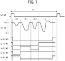
- FIG. 7 are timing charts for describing a generation operation of the drive waveform Vp and the drive waveform selection signals M0 to M4. Generation of the signals is initiated in synchronization with the line synchronization signal LS illustrated in (a) of FIG. 7 .
- the drive waveform Vp illustrated in (b) of FIG. 7 is a voltage waveform that is applied to the piezoelectric element 112, and is generated in one cycle T, for example, as a waveform illustrated in the drawing.
- "Ve" illustrated in (b) of FIG. 7 is a reference potential.
- (c-0) to (c-4) of FIG. 7 are drive waveform selection signals for ON/OFF switching the drive waveform Vp.
- the drive waveform selection signal M0 in (c-0) of FIG. 7 is a drive waveform selection signal corresponding to the case of discharge absence.
- the drive waveform selection signal M0 is held to the potential Ve.
- the drive waveform selection signal M1 in (c-1) of FIG. 7 is a signal corresponding to small droplet discharge. Application illustrated in a period of "iv” in (b) of FIG. 7 is performed.
- the drive waveform selection signal M2 in (c-2) of FIG. 7 is a signal corresponding to intermediate droplet discharge. Application is performed in periods of "ii” and “iv” in (b) of FIG. 7 .
- a drive waveform selection signal M3 in (c-3) of FIG. 7 is a signal corresponding to large droplet discharge. Application is performed in periods of "ii", “iii”, and “iv” in (b) of FIG. 7 . In this manner, ink droplets are continuously discharged while changing a droplet speed by using a drive waveform including a plurality of pulse arrays in the print cycle T, and the ink droplets are integrated into one liquid droplet in flight to form a large droplet.
- the drive waveform selection signal M4 in (c-4) of FIG. 7 is a signal corresponding to meniscus vibration. Application is performed in a period of "i" in (b) of FIG. 7 . A pulse amplitude in the period of "i” is set so that discharge from a nozzle is not performed, and a meniscus is vibrated without discharge.
- the selection part 46 selects one of the drive waveform selection signals M0 to M4 in accordance with image data indicating discharge presence/absence, or an ink droplet amount that is discharged to perform on/off control of the switch 45.
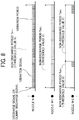
- FIG. 8 is a view for describing two meniscus vibration control methods including "a control method for vibrating the meniscus immediately before discharge during the printing operation” and "a control method for continuously vibrating the meniscus in the non-discharge period during the printing operation".
- a non-discharge period TNP1 sandwiched between a discharge signal and a dummy discharge signal of a nozzle N is greater than a threshold value X, and thus "a control method for continuously vibrating the meniscus in the non-discharge period during the printing operation" in which the meniscus is continuously vibrated in a period before subsequent discharge is applied.
- a vibration period a vibration signal is continuously input in an arbitrary drive cycle, and the meniscus vibration is continuously performed.
- the arbitrary drive cycle in which the vibration is performed may be the same as a minimum discharge cycle during printing which is determined by print mode resolution and a linear speed (a relative speed of a recording medium in a direction orthogonal to a nozzle array direction, that is, a conveyance speed of the recording medium 1 in the aspect of FIG. 1 , or a scanning speed of the carriage 13 during printing in the aspect of FIG. 5 ) which are included in print conditions.
- the arbitrary drive cycle may be set differently from the minimum discharge cycle during printing only in a vibration cycle as in a nozzle N+1.
- Non-discharge periods TNP3 and TNP4 of a nozzle N+2 is smaller than the threshold value X, and thus "a control method for vibrating the meniscus immediately before discharge during the printing operation" in which the meniscus is vibrated immediately before subsequent discharge is applied. Vibration of the meniscus is performed in a constant drive cycle immediately before subsequent discharge.
- the optimal number of times of vibration of the meniscus is different depending on the non-discharge period. According to this, it is preferable that the number of times of execution of meniscus vibration immediately before discharge is determined in correspondence with the non-discharge period.
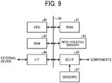
- FIG. 9 is a view illustrating a hardware configuration of the controller 34.
- the controller 34 includes a central processing unit (CPU) 80 that performs control of the entirety of the image forming apparatus according to the embodiment, and a read only memory (ROM) 81 that stores information, a control program, and the like.
- An image forming program for determining and controlling a meniscus vibration control method to be described later is illustrative only and is stored in a ROM 81.
- the controller 34 includes a random access memory (RAM) 82 (the RAM 82 may be divided into a RAM for a program and a RAM for image processing) that is used as a working memory or the like, and a non-volatile memory 83 that stores device-specific information, or information that can be updated.
- RAM random access memory
- the controller 34 includes an interface unit 84 that relays information exchange with an external device (a host computer or the like), and an input output interface (IOI/F) 85 that performs information exchange with respective components in the apparatus.
- the CPU 80 to IOI/F 85 are connected to each other through a memory bus 86.
- the memory bus may be divided into a plurality of buses.
- an input/output device such as an operation panel, sensors 87, and the like are also connected to the IO interface 85.
- the sensors 87 include a home position sensor of the carriage, a paper position detection sensor, a sensor (environment detector) that detects an interior or nearby environment (a temperature, humidity, or the like) of the apparatus, and the like.
- the threshold value X for determining the meniscus vibration control method is stored in the ROM 81, and an optimal threshold value X is read out from the ROM 81 in correspondence with sensor information obtained by detecting the interior or nearby environment (a temperature, humidity, or the like) of the apparatus when determining the meniscus vibration control method.
- the threshold value X is determined on the basis of the non-discharge period leading to non-discharge in the control method for vibrating the meniscus only immediately before discharge during the printing operation, but the non-discharge period leading to non-discharge may be different when a nearby environment varies, and thus it is preferable that the non-discharge period is obtained in advance through a discharge experiment or the like, and is updated in correspondence with the nearby environment.
- FIG. 10 is a flowchart of control of determining whether to vibrate the meniscus immediately before discharge or to continuously vibrate the meniscus in the head driver 31 and the signal generator relating to head drive in FIG. 6 .
- Each control in the flowchart is executed on the basis of an image forming program stored in a storage unit such as the ROM 81.
- the control is performed for each nozzle provided in the recording head 3.
- step S1 when image data is input (step S1), the input image data is converted into print data (a large droplet, an intermediate droplet, a small droplet, and discharge absence) (step S2).
- the non-discharge period detector 44 detects a site of the "discharge absence" in the print data, and detects the non-discharge period from the number of times of continuous data of discharge absence (step S3).
- print resolution included in print image data a linear speed (a relative speed of a recording medium in a direction orthogonal to a nozzle array direction. That is, a conveyance speed of the recording medium 1 in the aspect of FIG. 1 , or a scanning speed of the carriage 13 during printing in the aspect of FIG. 5 ), and information between sheets of paper are used.
- the meniscus vibration control method determination unit 43 it is determined whether to vibrate the meniscus immediately before discharge or to continuously vibrate the meniscus in correspondence with the non-discharge period calculated by the non-discharge period detector 44 and threshold value X (step S4). It is desirable that the threshold value X at this time include an optimal value in accordance with a use environment.
- step S5 the meniscus vibration control method is determined as “a control method for continuously vibrating the meniscus in the non-discharge period during the printing operation", and the converter 42 is notified of the signal "ShkM1".
- step S6 the meniscus vibration control method is determined as "a control method for vibrating the meniscus immediately before discharge during the printing operation", and the converter 42 is notified of the signal "ShkM2".
- the converter 42 converts print data input from the buffer 41 into print data in accordance with the signal given in the notification, and outputs the converted data to the drive waveform output selector 37. Then, a drive waveform is selected in accordance with the data input to the drive waveform output selector 37 and is output to the piezoelectric element 112 (step S7).
- the non-discharge period detector 44 confirms whether or not print data indicating "discharge absence" remains in non-detected print data (step S8). In a case where the print data indicating "discharge absence” remains, the process from step S3 is repetitively executed. In a case where the print data indicating "discharge absence" does not remain, the process in the flowchart of FIG. 10 is terminated (completed).
- FIG. 11 is a characteristic diagram illustrating that a discharge speed is recovered to a normal state when discharging how many droplets (vertical axis) with respect to the non-discharge period (horizontal axis).
- the threshold value X is a temperature of 23°C and relative humidity of 50%.
- the characteristic diagram of FIG. 11 illustrates two conditions including the case of vibrating the meniscus only immediately before a first droplet of recovery discharge (6000 times at 24 kHz) without vibrating the meniscus in the non-discharge period, and the case of continuously vibrating the meniscus (24 kHz) at all times in the non-discharge period.
- the threshold value X is set to 50 seconds in consideration of a variation.
- the image forming apparatus since setting of the threshold value X is set in advance for each use environment temperature and humidity, it is possible to determine whether to vibrate the meniscus only immediately before discharge or to continuously vibrate the meniscus in accordance with the non-discharge period during the printing operation, and it is possible to suppress "shortening of a time until reaching non-discharge" that is an adverse effect of the control of vibrating the meniscus only immediately before discharge.
- the meniscus vibration control method includes "a control method for vibrating the meniscus immediately before discharge during the printing operation” and "a control method for continuously vibrating the meniscus in the non-discharge period during the printing operation".
- a control method for vibrating the meniscus immediately before discharge during the printing operation and "a control method for continuously vibrating the meniscus in the non-discharge period during the printing operation.
- the threshold value for determining a "method for vibrating the meniscus only immediately before discharge during the printing operation” or a “method for continuously vibrating the meniscus in the non-discharge period during the printing operation” is changed in accordance with a use environment. According to this, it is possible to suppress non-discharge that occurs due to thickening of ink in the non-discharge period regardless of an environment.
- viscosity of ink varies depending on an environment inside the apparatus, or "temperature”, “relative humidity or absolute humidity”, or “atmospheric pressure” of a nearby environment, and thus the non-discharge period leading to non-discharge in the control method for vibrating the meniscus only immediately before discharge during the printing operation varies.
- the present invention can be implemented in any convenient form, for example using dedicated hardware, or a mixture of dedicated hardware and software.
- the present invention may be implemented as computer software implemented by one or more networked processing apparatuses.
- the processing apparatuses include any suitably programmed apparatuses such as a general purpose computer, personal digital assistant, mobile telephone (such as a WAP or 3G-compliant phone) and so on. Since the present invention can be implemented as software, each and every aspect of the present invention thus encompasses computer software implementable on a programmable device.
- the computer software can be provided to the programmable device using any conventional carrier medium (carrier means).
- the carrier medium includes a transient carrier medium such as an electrical, optical, microwave, acoustic or radio frequency signal carrying the computer code.
- transient medium is a TCP/IP signal carrying computer code over an IP network, such as the Internet.
- the carrier medium may also include a storage medium for storing processor readable code such as a floppy disk, hard disk, CD ROM, magnetic tape device or solid state memory device.
Landscapes
- Ink Jet (AREA)
- Particle Formation And Scattering Control In Inkjet Printers (AREA)
Abstract
An image forming apparatus includes a recording head (3), a non-discharge period detector (44), a control method determination unit (43), and a drive waveform output unit (37). The recording head (3) includes nozzles (104) and pressure generation elements (112) disposed corresponding to the nozzles (104). The non-discharge period detector (44) detects a non-discharge period of the nozzles (104) during a printing operation for each nozzle. The control method determination unit (43) determines a meniscus vibration control method executed in the non-discharge period on basis of the non-discharge period detected by the non-discharge period detector (44). The drive waveform output unit (37) drives a corresponding pressure generation element among the pressure generation elements (112) in accordance with the meniscus vibration control method determined by the control method determination unit (43) to vibrate meniscus of ink so that the ink is not discharged in the non-discharge period.
Description
- The present invention relates to an image forming apparatus, an image forming method, and an image forming program.
- In an inkjet type image forming apparatus, to suppress an ink viscosity increase in a nozzle section which occurs in a non-discharge period during printing waiting or continuous printing, typically, a meniscus of ink is vibrated to a certain extent in which the ink is not discharged from a nozzle in a non-discharge period to stir the ink in a nozzle. According to this, the ink viscosity in the nozzle is made to be uniform.
- According to this, the image forming apparatus copes with a disadvantage of image deterioration due to discharge failure such as non-discharge caused by a viscosity increase and occurrence of satellite or mist (dust), or a failure of landing to a desired position at a desired droplet amount due to a decrease of a discharge speed or a discharge droplet amount from a desired value.
- However, the higher a water concentration of ink near a meniscus is (that is, a state of not being thickened), the faster a moisture evaporation speed from a nozzle is. Therefore, the meniscus is vibrated as described above, the state in which the water concentration of ink near the meniscus is high continues, and thus drying is further promoted. That is, a total amount of moisture evaporated increases (the amount of ink thickened increases), and thus there is a disadvantage that a dummy discharge amount required for recovery and a discharge frequency increases.
- To solve the disadvantage, a technology in which the number of vibration pulses of the meniscus when discharging after the non-discharge period continues is determined in correspondence with the non-discharge period, meniscus vibration in a required amount is performed only immediately before discharge, and meniscus vibration more than required is not performed to suppress the amount of moisture evaporated from a nozzle is considered and already known.
- However, in the case of vibrating the meniscus only immediately before discharge, when the non-discharge period is long, thickening on a meniscus surface proceeds.
Therefore, there is a disadvantage that stirring efficiency of ink inside a nozzle when vibrating the meniscus deteriorates, and a time until reaching non-discharge is further shortened in comparison to the case of continuously vibrating the meniscus. - A countermeasure of discharging thickened ink before non-discharge is also considered against the disadvantage in which the time until reaching non-discharge is shortened. However, since the time until reaching non-discharge is shortened, a discharge frequency is required to further increase in comparison to the case of continuously vibrating the meniscus. According to this, a disadvantage occurs that the increase leads to deterioration of productivity due to a discharge operation, or an increase in the amount of ink discharged.
- The invention has been made in consideration of such circumstances, and an object of the invention is to provide an image forming apparatus, an image forming method, and an image forming program which are capable of suppressing shortening of a time until reaching non-discharge without increasing a discharge frequency of thickened ink in a control method for vibrating a meniscus only immediately before discharge.
- To solve the above-described problem and achieve the purpose, according to an aspect of the present invention, an image forming apparatus includes a recording head (3), a non-discharge period detector (44), a control method determination unit (43), and a drive waveform output unit (37). The recording head (3) includes a plurality of nozzles (104) and a plurality of pressure generation elements (112) disposed corresponding to the plurality of nozzles (104). The non-discharge period detector (44) detects a non-discharge period of the plurality of nozzles (104) during a printing operation for each nozzle. The control method determination unit (43) determines a meniscus vibration control method executed in the non-discharge period on basis of the non-discharge period detected by the non-discharge period detector (44). The drive waveform output unit (37) drives a corresponding pressure generation element among the plurality of pressure generation elements (112) in accordance with the meniscus vibration control method determined by the control method determination unit (43) to vibrate meniscus of ink so that the ink is not discharged in the non-discharge period.
- According to the invention, in a control method for vibrating the meniscus only immediately before discharge, it is possible to attain an effect capable of suppressing shortening of a time until reaching non-discharge without increasing a discharge frequency of thickened ink.
- A more complete appreciation of the disclosure and many of the attendant advantages and features thereof can be readily obtained and understood from the following detailed description with reference to the accompanying drawings, wherein:
-
FIG. 1 is a view illustrating an image forming apparatus according to an embodiment from a vertical direction of a recording medium, and is a view illustrating a schematic configuration of the image forming apparatus; -
FIG 2 is a schematic view of a recording head; -
FIG. 3 is a cross-sectional view illustrating a configuration of a liquid discharge head that constitutes the recording head; -
FIG. 4 is a cross-sectional view illustrating another configuration of the liquid discharge head that constitutes the recording head; -
FIG. 5 is a view illustrating a configuration of a serial type inkjet recording apparatus; -
FIG. 6 includingFIGS. 6A and6B is a block diagram of a head driver to drive a piezoelectric element to drive a nozzle of the recording head to discharge a liquid droplet, and a signal generator relating to head drive; -
FIG. 7 is a timing chart for describing a generation operation of a drive waveform of the piezoelectric element and a drive waveform selection signal; -
FIG. 8 is a diagram for describing two meniscus vibration control methods including "a control method for vibrating the meniscus immediately before discharge during the printing operation" and "a control method for continuously vibrating the meniscus in the non-discharge period during the printing operation"; -
FIG. 9 is a diagram illustrating a hardware configuration of a controller; -
FIG. 10 is a flowchart of control of determining whether to vibrate a meniscus only immediately before discharge or to continuously vibrate the meniscus in a head driver and a signal generator relating to head drive; and -
FIG. 11 is a characteristic diagram illustrating that a discharge speed is recovered to a normal state when discharging how many droplets with respect to the non-discharge period. - The accompanying drawings are intended to depict embodiments of the present invention and should not be interpreted to limit the scope thereof. The accompanying drawings are not to be considered as drawn to scale unless explicitly noted.
- The terminology used herein is for the purpose of describing particular embodiments only and is not intended to be limiting of the present invention. As used herein, the singular forms "a", "an" and "the" are intended to include the plural forms as well, unless the context clearly indicates otherwise.
- In describing embodiments illustrated in the drawings, specific terminology is employed for the sake of clarity. However, the disclosure of this specification is not intended to be limited to the specific terminology so selected and it is to be understood that each specific element includes all technical equivalents that have a similar function, operate in a similar manner, and achieve a similar result.
- Hereinafter, an image forming apparatus, an image forming method, and an image forming program according to an embodiment will be described.
- First, description will be given of the reason why a time until reaching non-discharge is further shortened in the case of vibrating a meniscus only immediately before discharge in comparison to the case of continuously vibrating the meniscus.
- In a technology of vibrating the meniscus only immediately before discharge, meniscus vibration is not performed in a non-discharge period, and thus ink viscosity of a meniscus surface that is in contact with the atmospheric air increases, and the resultant thickened ink functions as a lid of a nozzle, and moisture evaporation from a nozzle is suppressed. In addition, the meniscus is vibrated only before discharge to break down the lid immediately before discharge, and discharge is performed with ink of which moisture evaporation is less (viscosity increase is small).
- According to this, when the non-discharge period is excessively long, the ink viscosity on the meniscus surface excessively increases, and thus even though meniscus vibration is applied, the lid is less likely to be broken.
- On the other hand, when continuously vibrating the meniscus, ink inside the nozzle is stirred, and ink viscosity inside the nozzle is made to be uniform. Accordingly, it is possible to further lengthen a time until reaching ink viscosity leading to non-discharge in comparison to the case of vibrating the meniscus only immediately before discharge. However, the entirety of ink inside the nozzle is gradually thickened due to uniformity, and thus the amount of ink thickened becomes greater in comparison to vibrating the meniscus only immediately before discharge. As a result, there is a demerit that the amount of ink discharged as thickened ink increases.
- The image forming apparatus according to the embodiment is an example in which a determination is made as to whether to vibrate the meniscus only immediately before discharge or to continuously vibrate the meniscus (a distinction is made between the two cases) in accordance with a non-discharge period during a printing operation, and in the case of a non-discharge period in which non-discharge occurs only when vibrating the meniscus only immediately before discharge, the meniscus is vibrated in association.
-
FIG. 1 is a view illustrating the image forming apparatus according to the embodiment from a vertical direction of arecording medium 1, and is a view illustrating a schematic configuration of the image forming apparatus. The image forming apparatus according to the embodiment is a line-scanning type inkjet recording apparatus. For example, therecording medium 1 is paper. In addition, therecording medium 1 may be roll paper (continuous paper) or cut paper, and a shape is not limited. In addition, therecording medium 1 may be various media other than the paper. Therecording medium 1 is conveyed in a predetermined direction (an arrow direction inFIG. 1 ). - A
recording device 2 is provided to face a recording surface of therecording medium 1 while maintaining a predetermined distance. Therecording device 2 includes a plurality ofrecording devices - When the
recording device 2 discharges ink droplets in synchronization with a paper conveyance speed, a color image is formed on therecording medium 1. Note that, the image forming apparatus is provided with a mechanism that controls conveyance so that therecording medium 1 passes at a predetermined speed, and at a predetermined position with respect to therecording device 2. Illustration and description of the conveyance mechanism will be omitted. - The
recording devices FIG. 1 . When the recording heads 3 are arrayed as described above, it is possible to secure a wide printing region width. -
FIG. 2 is a schematic view of therecording head 3. As illustrated inFIG. 2 , in therecording head 3, a plurality ofnozzles 104 is arranged in a predetermined pitch p in a direction (hereinafter, referred to as "nozzle array direction") orthogonal to the conveyance direction. In the case of therecording head 3 in the example ofFIG. 2 , two pieces of the nozzle arrays are separately provided. The nozzles are arranged to deviate from each other by approximately 1/2·p in the nozzle array direction, and thus recording with high definition can be performed in the nozzle array direction. -
FIG. 3 and FIG. 4 are cross-sectional views illustrating a configuration of a liquid discharge head that constitutes therecording head 3. Specifically,FIG. 3 and FIG. 4 are cross-sectional views taken along a liquid chamber longitudinal direction (direction orthogonal to the nozzle array direction) of therecording head 3. InFIG. 3 and FIG. 4 , therecording head 3 includes an individual liquid chamber 106 (referred to as a pressurizing chamber, a pressurizing liquid chamber, a pressure chamber, an individual flow passage, a pressure generation chamber, or the like. Hereinafter, referred to simply as "liquid chamber") which is formed by joining aflow passage plate 101, avibration plate member 102, and anozzle plate 103, and with which each of thenozzles 104 discharging liquid droplets communicates through a through-hole 105. In addition, therecording head 3 includes a fluidresistant part 107 that supplies a liquid to theliquid chamber 106, and aliquid introduction part 108. In therecording head 3, liquid (ink) is introduced to theliquid introduction part 108 from acommon liquid chamber 110 formed in aframe member 117 through afilter 109 formed in thevibration plate member 102, and the ink is supplied from theliquid introduction part 108 to theliquid chamber 106 through the fluidresistant part 107. - For example, the
flow passage plate 101 forms an opening or a groove such as the through-hole 105, theliquid chamber 106, the fluidresistant part 107, and theliquid introduction part 108 by laminating a metal plate such as stainless steel (SUS). - The
vibration plate member 102 is a wall surface member that forms a wall surface of theliquid chamber 106, the fluidresistant part 107, theliquid introduction part 108, and the like, and forms thefilter 109. Note that, as theflow passage plate 101, a member formed by anisotropically etching a silicon substrate may be used without limitation to the metal plate such as SUS. A lamination typepiezoelectric element 112, which is a columnar electromechanical conversion element as a drive element (an actuator part or a pressure generation part) that generates energy for pressurizing ink in theliquid chamber 106 to discharge liquid droplets from thenozzle 104, is joined to a surface of thevibration plate member 102 which is opposite to theliquid chamber 106. - An end of the
piezoelectric element 112 is joined to abase member 113. In addition, a flexible printed circuit board (FPC board) 115 that delivers a drive waveform is connected to thepiezoelectric element 112. Apiezoelectric actuator 111 is constituted by the above-described constituent elements. Note that, in this example, thepiezoelectric element 112 is used in a d33 mode in which expansion/contraction occurs in a lamination direction, but a d31 mode in which expansion/contraction occurs in a direction orthogonal to the lamination direction may be used. - In the liquid discharge head configured as described above, when a voltage that is applied to the
piezoelectric element 112 is lowered from a reference potential Ve, for example, as illustrated inFIG. 3 , thepiezoelectric element 112 contracts, thevibration plate member 102 is deformed, and the volume of theliquid chamber 106 expands. According to this, ink flows into theliquid chamber 106. Next, when the voltage that is applied to thepiezoelectric element 112 is raised, as illustrated inFIG. 4 , thepiezoelectric element 112 expands in the lamination direction, thevibration plate member 102 is deformed in a direction of thenozzle 104, and thus the volume of theliquid chamber 106 contracts. According to this, ink in theliquid chamber 106 is pressurized, and thus aliquid droplet 301 is discharged from thenozzle 104. - When the voltage applied to the
piezoelectric element 112 is returned to the reference potential Ve, thevibration plate member 102 is recovered to an initial position, theliquid chamber 106 expands, and thus a negative pressure occurs. According to this, theliquid chamber 106 is filled with ink from thecommon liquid chamber 110. After vibration of a meniscus surface of thenozzle 104 is attenuated and stabilized, a process transitions to an operation for subsequent liquid discharge. - However, the
liquid droplet 301 discharged from thenozzle 104 lands on therecording medium 1 that is maintained at a constant distance L after a flying time Tj. When a discharge speed of theliquid droplet 301 at this time is set as Vj, a relationship of Tj = L/Vj is satisfied. The discharge speed Vj may fluctuate in accordance with thickening of ink near thenozzle 104, and thus the flying time Tj may be different. In addition, therecording medium 1 is conveyed at a constant speed, and thus a variation occurs in a landing position in the conveyance direction. In addition, a variation also occurs in a droplet amount that is discharged. - In a case where the image forming apparatus according to the embodiment is a serial type inkjet recording apparatus, a configuration of the apparatus is illustrated in
FIG. 5 . That is, inFIG. 5 , in the image forming apparatus, acarriage 13 is held by master and slave guiderods recording medium 1. In addition, in the image forming apparatus, thecarriage 13 is moved and scanned in carriage scanning directions indicated by an arrow inFIG. 5 through a timing belt by a main scanning motor. - Recording heads 14 (14a and 14b) which discharge ink droplets of respective colors including yellow (Y), cyan (C), magenta (M), and key plate (K: may be black) are arranged in the
carriage 13 so that nozzle arrays are orthogonal to the main scanning direction. Thecarriage 13 is mounted in a state in which an ink droplet discharge direction faces a downward direction. - Each of the recording heads 14 includes two nozzle arrays, one nozzle array of the
recording head 14a discharges liquid droplets of key plate (K: may be black), the other nozzle array of therecording head 14a discharges liquid droplets of cyan (C), one nozzle array of therecording head 14b discharges liquid droplets of magenta (M), and the other nozzle array of therecording head 14b discharges liquid droplets of yellow (Y). When the recording heads 14 are driven in correspondence with an image signal while moving thecarriage 13, ink droplets are discharged to therecording medium 1 that is stopped to perform recording corresponding to one scanning, and after conveying therecording medium 1 by a predetermined amount, recording of a next row is performed. - In addition, a
retention recovery mechanism 15 of the recording heads 14 is provided in a region that does not overlap therecording medium 1 on a right side of thecarriage 13 in the scanning direction. During printing waiting, and the like, thecarriage 13 moves to the position, and a retention recovery operation of removing contaminants on a nozzle surface of the recording heads 14 or in the nozzles is performed. In addition, at the time of dummy discharge during the printing operation, thecarriage 13 is moved to the position, and thickened ink is discharged. Note that, even in the case of the serial type inkjet recording apparatus, a configuration of the liquid discharge head that constitutes the recording heads 14 is similar to the configuration as illustrated inFIG. 3 and FIG. 4 . -
FIG. 6 is a block diagram of ahead driver 31 that drives N pieces of piezoelectric elements 112-1 to 112-N which are driven to discharge liquid droplets from N pieces of nozzles provided in the recording heads 3 or the recording heads 14, and a signal generator relating to the head drive. Thehead driver 31 drives the piezoelectric elements corresponding to one nozzle array of the recording heads 3 or the recording heads 14. For example, in the case of the image forming apparatus according to the embodiment illustrated inFIG. 1 , thehead driver 31 is provided for each recording head and for each nozzle array. - Electrodes on one side of the
piezoelectric elements 112 are connected to a common potential (for example, a ground) through theFPC board 115 that delivers a drive waveform, and electrodes on the other side are connected to thehead driver 31. - The
head driver 31 includes one or a plurality of integrated circuits, and at least a portion connected to the piezoelectric elements is provided in theFPC board 115. - A print
signal control unit 33 separates image data to be printed into a plurality of pieces of image data corresponding to respective recording heads and nozzle arrays, and transmits the plurality of pieces of image data to thehead driver 31. In addition, the printsignal control unit 33 generates a line synchronization signal LS that becomes a reference of printing. Discharge is performed from N pieces of nozzles driven by the onehead driver 31 in synchronization with the line synchronization signal LS to form one dot array (hereinafter, appropriately referred to as "line") on therecording medium 1. - A cycle T of the line synchronization signal LS is determined by a relative speed of the recording medium in a direction orthogonal to a nozzle array direction (that is, a conveyance speed of the
recording medium 1 in the aspect inFIG. 1 , and a scanning speed of thecarriage 13 during printing in the aspect ofFIG. 5 ), and printing resolution (line resolution) in the direction. That is, dots of one pixel are formed in the cycle T. The line synchronization signal LS is supplied to a drive waveform generator 32, and is used as an initiation reference of drive waveform generation. In addition, the line synchronization signal LS is also used as a line synchronization signal when transmitting image data to thehead driver 31. - Note that, it is more preferable that the line synchronization signal LS is generated for each corresponding head driver, and a timing is adjusted so that positions of dots formed from respective nozzle arrays are aligned.
- In addition, with regard to transmission of image data from the print
signal control unit 33 to thehead driver 31, print data of N pieces of nozzles, which is printed in one line cycle, is serially transmitted in a state in which the line synchronization signal LS is set as a transmission initiation reference and a transmission clock SCK is set as a reference. - The drive waveform generator 32 generates a drive waveform Vp for driving each of the
piezoelectric elements 112. The drive waveform generator 32 initiates generation of the drive waveform Vp with the line synchronization signal LS set as a reference. In a plurality of drive waveform output selectors 37 (an example of a vibration waveform output unit) provided in thehead driver 31 in correspondence with thepiezoelectric element 112, a part or all of time-divided drive waveforms are selected, and are applied to the piezoelectric element. Detailed example of the drive waveform will be described later. - A controller 34 is connected to an external device (for example, a host computer), and receives a print request and a print image. The print image is supplied to the print
signal control unit 33 on the basis of the print request. In addition, the controller 34 has a function of setting drive waveform information that is generated by the drive waveform generator 32, or a function of setting information for controlling thehead driver 31. - Note that, the
head driver 31 can be provided integrally with the recording heads 3. When being integrally formed, a recording head unit of this embodiment is constituted. - Hereinafter, a detailed configuration of the
head driver 31 will be described. N pieces of print data corresponding to data of one line of the recording heads 3 are serially input from the printsignal control unit 33 in synchronization with the transmission clock SCK. The N pieces of print data which are serially input are sequentially retained in ashift register 35. For example, when assuming that ink droplets corresponding to different dots with four sizes including a large droplet, an intermediate droplet, a small droplet, and discharge absence are discharged from nozzles of the recording heads 3, one piece of print data is two-bit data. In this embodiment, it is assumed that the print data indicates the large droplet of "3", the intermediate droplet of "2", the small droplet of "1", and the discharge absence of "0". - A
latch 36 includes N pieces of latches which retain N pieces of print data retained by theshift register 35 at once in accordance with an input of the line synchronization signal LS. Thelatch 36 retains pieces of data (D1 to DN) of two bits per one piece of data, and supplies the pieces of data to a correspondingvibration instruction unit 38. - N pieces of the
vibration instruction units 38 is provided in correspondence with thepiezoelectric elements 112 which are driven, and each of thevibration instruction units 38 includes abuffer 41, aconverter 42, a meniscus vibration control method determination unit 43, and a non-discharge period detector 44. For example, thebuffer 41 is a first in first out (FIFO) type buffer that is constituted by a shift register of Nb stages, or the like. Print data corresponding to a plurality of lines Nb is stored in thebuffer 41, and print data Dn (n represents 1 to N as a nozzle number) that is an output of thelatch 36 is input to thebuffer 41 whenever the line synchronization signal LS is input, and the oldest print data stored is output from thebuffer 41. - The non-discharge period detector 44 detects how long period (how many lines) non-discharge (discharge absence) of the print data Dn continues. The meniscus vibration control method determination unit 43 determines a meniscus vibration control method up to discharge that continues in the non-discharge period in correspondence with a non-discharge period that is detected by the non-discharge period detector 44, and a threshold value X that is determined in advance, and outputs the meniscus vibration control method to the
converter 42. - In a case where a signal of the meniscus vibration control method output from the meniscus vibration control method determination unit 43 is ShkM1 ("a control method for continuously vibrating the meniscus in the non-discharge period during the printing operation"), and print data input from the
buffer 41 before subsequent discharge is performed indicates discharge absence, theconverter 42 converts the signal into data indicating meniscus vibration and outputs the data. - In addition, in a case where the signal of the meniscus vibration control method output from the meniscus vibration control method determination unit 43 is ShkM2 ("a control method for vibrating the meniscus immediately before discharge during the printing operation"), the
converter 42 is notified of the number of meniscus vibration pulses Nshk in combination with the ShkM2, monitors an output of before Nshk+1 stage from a final stage of thebuffer 41. When the output becomes print data indicating discharge, theconverter 42 converts the output into data indicating meniscus vibration, and outputs the data. - In this manner, the
vibration instruction unit 38 converts the print data to perform meniscus vibration in a predetermined number of times immediately before discharge in correspondence with the non-discharge period of a corresponding nozzle, and supplies the converted print data to a corresponding drivewaveform output selector 37. - A drive waveform
selection signal generator 39 generates a drive waveform selection signal indicating that which portion of the drive waveform Vp is selected and is supplied to each of thepiezoelectric elements 112 in synchronization with the drive waveform Vp with the line synchronization signal LS set as a generation initiation reference. For example, the drive waveformselection signal generator 39 generates drive waveform selection signals for the large droplet (M3), the intermediate droplet (M2), the small droplet (M1), the discharge absence (M0), and meniscus vibration (M4). - N pieces of the drive
waveform output selectors 37 are provided in correspondence with thepiezoelectric elements 112 which are driven. Each of the drivewaveform output selectors 37 includes aselection part 46 that selects one of drive waveform selection signals M0 to M4 in accordance with image data supplied from thevibration instruction unit 38, and a switch 45 that performs ON/OFF switching of the drive waveform Vp in accordance with the selected drive waveform selection signal. A drive waveform corresponding to image data is partially selected and output to thepiezoelectric element 112. - A
head control unit 40 performs control of the entirety of thehead driver 31. In addition, thehead control unit 40 has a function of performing communication with the controller 34, and performs setting of information to each block or updating of the information. - (a), (b), and (c-0) to (c-4) of
FIG. 7 are timing charts for describing a generation operation of the drive waveform Vp and the drive waveform selection signals M0 to M4. Generation of the signals is initiated in synchronization with the line synchronization signal LS illustrated in (a) ofFIG. 7 . The drive waveform Vp illustrated in (b) ofFIG. 7 is a voltage waveform that is applied to thepiezoelectric element 112, and is generated in one cycle T, for example, as a waveform illustrated in the drawing. "Ve" illustrated in (b) ofFIG. 7 is a reference potential. (c-0) to (c-4) ofFIG. 7 are drive waveform selection signals for ON/OFF switching the drive waveform Vp. In a period in which the drive waveform selection signal is "H", a switch is turned on, and a drive waveform is applied to the piezoelectric element. In addition, in a period in which the drive waveform selection signal is "L", the switch is turned off, and a potential immediately before the period is held. An applied waveform varies depending on which portion of the drive waveform Vp is selected and output, and discharge presence/absence, and an ink droplet amount that is discharged from the nozzle vary. - The drive waveform selection signal M0 in (c-0) of
FIG. 7 is a drive waveform selection signal corresponding to the case of discharge absence. The drive waveform selection signal M0 is held to the potential Ve. When the switch 45 is turned off for a long period, and a state in which a signal is not applied to thepiezoelectric element 112 continues, a potential is lowered due to natural discharging, and thus a period of the potential Ve is set to "H" to be applied. - The drive waveform selection signal M1 in (c-1) of
FIG. 7 is a signal corresponding to small droplet discharge. Application illustrated in a period of "iv" in (b) ofFIG. 7 is performed. The drive waveform selection signal M2 in (c-2) ofFIG. 7 is a signal corresponding to intermediate droplet discharge. Application is performed in periods of "ii" and "iv" in (b) ofFIG. 7 . - A drive waveform selection signal M3 in (c-3) of
FIG. 7 is a signal corresponding to large droplet discharge. Application is performed in periods of "ii", "iii", and "iv" in (b) ofFIG. 7 . In this manner, ink droplets are continuously discharged while changing a droplet speed by using a drive waveform including a plurality of pulse arrays in the print cycle T, and the ink droplets are integrated into one liquid droplet in flight to form a large droplet. - The drive waveform selection signal M4 in (c-4) of
FIG. 7 is a signal corresponding to meniscus vibration. Application is performed in a period of "i" in (b) ofFIG. 7 . A pulse amplitude in the period of "i" is set so that discharge from a nozzle is not performed, and a meniscus is vibrated without discharge. - The
selection part 46 selects one of the drive waveform selection signals M0 to M4 in accordance with image data indicating discharge presence/absence, or an ink droplet amount that is discharged to perform on/off control of the switch 45. -
FIG. 8 is a view for describing two meniscus vibration control methods including "a control method for vibrating the meniscus immediately before discharge during the printing operation" and "a control method for continuously vibrating the meniscus in the non-discharge period during the printing operation". - In
FIG. 8 , a non-discharge period TNP1 sandwiched between a discharge signal and a dummy discharge signal of a nozzle N is greater than a threshold value X, and thus "a control method for continuously vibrating the meniscus in the non-discharge period during the printing operation" in which the meniscus is continuously vibrated in a period before subsequent discharge is applied. In a vibration period, a vibration signal is continuously input in an arbitrary drive cycle, and the meniscus vibration is continuously performed. - The arbitrary drive cycle in which the vibration is performed may be the same as a minimum discharge cycle during printing which is determined by print mode resolution and a linear speed (a relative speed of a recording medium in a direction orthogonal to a nozzle array direction, that is, a conveyance speed of the
recording medium 1 in the aspect ofFIG. 1 , or a scanning speed of thecarriage 13 during printing in the aspect ofFIG. 5 ) which are included in print conditions. Alternatively, the arbitrary drive cycle may be set differently from the minimum discharge cycle during printing only in a vibration cycle as in anozzle N+ 1. - When the vibration cycle is excessively short, stirring of ink inside a nozzle is excessive, and average ink viscosity inside the nozzle rises within a short time, and thus there is a concern that discharge abnormality may occur. In contrast, when the vibration cycle is excessively long, viscosity of ink near a meniscus excessively rises, and thus ink stirring efficiency deteriorates, or stirring may be difficult. Therefore, it is preferable to set the vibration cycle with balance.
- Non-discharge periods TNP3 and TNP4 of a nozzle N+2 is smaller than the threshold value X, and thus "a control method for vibrating the meniscus immediately before discharge during the printing operation" in which the meniscus is vibrated immediately before subsequent discharge is applied. Vibration of the meniscus is performed in a constant drive cycle immediately before subsequent discharge.
- Since ink viscosity inside a nozzle is different in correspondence with the non-discharge period, the optimal number of times of vibration of the meniscus is different depending on the non-discharge period. According to this, it is preferable that the number of times of execution of meniscus vibration immediately before discharge is determined in correspondence with the non-discharge period.
-
FIG. 9 is a view illustrating a hardware configuration of the controller 34. As illustrated inFIG. 9 , the controller 34 includes a central processing unit (CPU) 80 that performs control of the entirety of the image forming apparatus according to the embodiment, and a read only memory (ROM) 81 that stores information, a control program, and the like. An image forming program for determining and controlling a meniscus vibration control method to be described later is illustrative only and is stored in a ROM 81. In addition, the controller 34 includes a random access memory (RAM) 82 (the RAM 82 may be divided into a RAM for a program and a RAM for image processing) that is used as a working memory or the like, and anon-volatile memory 83 that stores device-specific information, or information that can be updated. - In addition, the controller 34 includes an interface unit 84 that relays information exchange with an external device (a host computer or the like), and an input output interface (IOI/F) 85 that performs information exchange with respective components in the apparatus. The
CPU 80 to IOI/F 85 are connected to each other through amemory bus 86. The memory bus may be divided into a plurality of buses. - In addition to the
head driver 31, the drive waveform generator 32, and the printsignal control unit 33 illustrated inFIG. 6 , an input/output device such as an operation panel,sensors 87, and the like are also connected to the IO interface 85. Examples of thesensors 87 include a home position sensor of the carriage, a paper position detection sensor, a sensor (environment detector) that detects an interior or nearby environment (a temperature, humidity, or the like) of the apparatus, and the like. - In addition, the threshold value X for determining the meniscus vibration control method is stored in the ROM 81, and an optimal threshold value X is read out from the ROM 81 in correspondence with sensor information obtained by detecting the interior or nearby environment (a temperature, humidity, or the like) of the apparatus when determining the meniscus vibration control method.
- As described above, the threshold value X is determined on the basis of the non-discharge period leading to non-discharge in the control method for vibrating the meniscus only immediately before discharge during the printing operation, but the non-discharge period leading to non-discharge may be different when a nearby environment varies, and thus it is preferable that the non-discharge period is obtained in advance through a discharge experiment or the like, and is updated in correspondence with the nearby environment.
-
FIG. 10 is a flowchart of control of determining whether to vibrate the meniscus immediately before discharge or to continuously vibrate the meniscus in thehead driver 31 and the signal generator relating to head drive inFIG. 6 . Each control in the flowchart is executed on the basis of an image forming program stored in a storage unit such as the ROM 81. In addition, the control is performed for each nozzle provided in therecording head 3. - In the flowchart in
FIG. 10 , when image data is input (step S1), the input image data is converted into print data (a large droplet, an intermediate droplet, a small droplet, and discharge absence) (step S2). The non-discharge period detector 44 detects a site of the "discharge absence" in the print data, and detects the non-discharge period from the number of times of continuous data of discharge absence (step S3). In calculation, print resolution included in print image data, a linear speed (a relative speed of a recording medium in a direction orthogonal to a nozzle array direction. That is, a conveyance speed of therecording medium 1 in the aspect ofFIG. 1 , or a scanning speed of thecarriage 13 during printing in the aspect ofFIG. 5 ), and information between sheets of paper are used. - In the meniscus vibration control method determination unit 43, it is determined whether to vibrate the meniscus immediately before discharge or to continuously vibrate the meniscus in correspondence with the non-discharge period calculated by the non-discharge period detector 44 and threshold value X (step S4). It is desirable that the threshold value X at this time include an optimal value in accordance with a use environment.
- In the case of "non-discharge period t ≥ threshold value X" (step S5), the meniscus vibration control method is determined as "a control method for continuously vibrating the meniscus in the non-discharge period during the printing operation", and the
converter 42 is notified of the signal "ShkM1". In the case of "non-discharge period t < threshold value X" (step S6), the meniscus vibration control method is determined as "a control method for vibrating the meniscus immediately before discharge during the printing operation", and theconverter 42 is notified of the signal "ShkM2". - The
converter 42 converts print data input from thebuffer 41 into print data in accordance with the signal given in the notification, and outputs the converted data to the drivewaveform output selector 37. Then, a drive waveform is selected in accordance with the data input to the drivewaveform output selector 37 and is output to the piezoelectric element 112 (step S7). - The non-discharge period detector 44 confirms whether or not print data indicating "discharge absence" remains in non-detected print data (step S8). In a case where the print data indicating "discharge absence" remains, the process from step S3 is repetitively executed. In a case where the print data indicating "discharge absence" does not remain, the process in the flowchart of
FIG. 10 is terminated (completed). -
FIG. 11 is a characteristic diagram illustrating that a discharge speed is recovered to a normal state when discharging how many droplets (vertical axis) with respect to the non-discharge period (horizontal axis). The threshold value X is a temperature of 23°C and relative humidity of 50%. The characteristic diagram ofFIG. 11 illustrates two conditions including the case of vibrating the meniscus only immediately before a first droplet of recovery discharge (6000 times at 24 kHz) without vibrating the meniscus in the non-discharge period, and the case of continuously vibrating the meniscus (24 kHz) at all times in the non-discharge period. - As can be understood from the characteristic diagram of
FIG. 11 , in the case of vibrating the meniscus only immediately before discharge, it can be understood that the number of droplets discharged until recovery decreases in comparison to the case of continuously vibrating the meniscus, but a time until reaching non-discharge is shortened. From this result, in the case of vibrating the meniscus only immediately before discharge, it can be understood that non-discharge occurs when the non-discharge period becomes approximately 75 seconds. Accordingly, the threshold value X is set to 50 seconds in consideration of a variation. - As it becomes clear from the description, in the image forming apparatus according to the embodiment, since setting of the threshold value X is set in advance for each use environment temperature and humidity, it is possible to determine whether to vibrate the meniscus only immediately before discharge or to continuously vibrate the meniscus in accordance with the non-discharge period during the printing operation, and it is possible to suppress "shortening of a time until reaching non-discharge" that is an adverse effect of the control of vibrating the meniscus only immediately before discharge.
- In addition, the meniscus vibration control method includes "a control method for vibrating the meniscus immediately before discharge during the printing operation" and "a control method for continuously vibrating the meniscus in the non-discharge period during the printing operation". When properly using the two meniscus vibration control methods on the basis of the non-discharge period, it is possible to suppress "increase of a discharge frequency of thickened ink" and "shortening of a time until reaching non-discharge" as a technical problem in the case of using only the control method for vibrating the meniscus immediately before discharge during the printing operation.
- In addition, since determination of the meniscus vibration control method is made in accordance with the non-discharge period during the printing operation and the threshold value that is set in advance, it is possible to switch the control method at an optimal timing at which non-discharge does not occur in "a control method for vibrating the meniscus immediately before discharge during the printing operation".
- In addition, ink viscosity varies depending on an environment inside the image forming apparatus or a nearby environment, and thus the non-discharge period leading to non-discharge in the control method for vibrating the meniscus only immediately before discharge during the printing operation varies. Therefore, the threshold value for determining a "method for vibrating the meniscus only immediately before discharge during the printing operation" or a "method for continuously vibrating the meniscus in the non-discharge period during the printing operation" is changed in accordance with a use environment. According to this, it is possible to suppress non-discharge that occurs due to thickening of ink in the non-discharge period regardless of an environment.
- In addition, viscosity of ink varies depending on an environment inside the apparatus, or "temperature", "relative humidity or absolute humidity", or "atmospheric pressure" of a nearby environment, and thus the non-discharge period leading to non-discharge in the control method for vibrating the meniscus only immediately before discharge during the printing operation varies. Therefore, when changing the threshold value for determining the "method for vibrating the meniscus only immediately before discharge during the printing operation" or the "method for continuously vibrating the meniscus in the non-discharge period during the printing operation" in accordance with the "temperature", "the relative humidity or the absolute humidity", or the "atmospheric pressure", it is possible to suppress non-discharge that occurs due to thickening of ink in the non-discharge period regardless of an environment.
- In addition, in a case where the vibration cycle is excessively short, stirring of ink inside a nozzle becomes excessive, and average ink viscosity inside the nozzle rises within a short time, and this leads to discharge abnormality. In contrast, in a case where the vibration cycle is excessively long, ink viscosity near the meniscus that is in contact with the air is excessively raised, and thus ink stirring efficiency deteriorates or stirring may be difficult. Therefore, a meniscus vibration cycle is set differently from the drive cycle during printing. According to this, it is possible to set the vibration cycle with balance so that excess and deficiency of stirring disappears, and thus it is possible to suppress occurrence of a failure due to excess and deficiency of the stirring.
- Finally, the embodiment has been presented by way of one example, and is not intended to limit the scope of the inventions. Indeed, the novel embodiment described herein can be embodied in a variety of other forms; various omissions, substitutions, and changes in the form of the embodiment described herein can be made without departing from the spirit of the inventions. Further, the accompanying claims and their equivalents are intended to cover such embodiments or modifications as would fall within the scope and spirit of the inventions.
- The above-described embodiments are illustrative and do not limit the present invention. Thus, numerous additional modifications and variations are possible in light of the above teachings. For example, elements and/or features of different illustrative embodiments may be combined with each other and/or substituted for each other within the scope of the present invention.
- Any one of the above-described operations may be performed in various other ways, for example, in an order different from the one described above.
- The present invention can be implemented in any convenient form, for example using dedicated hardware, or a mixture of dedicated hardware and software. The present invention may be implemented as computer software implemented by one or more networked processing apparatuses. The processing apparatuses include any suitably programmed apparatuses such as a general purpose computer, personal digital assistant, mobile telephone (such as a WAP or 3G-compliant phone) and so on. Since the present invention can be implemented as software, each and every aspect of the present invention thus encompasses computer software implementable on a programmable device. The computer software can be provided to the programmable device using any conventional carrier medium (carrier means). The carrier medium includes a transient carrier medium such as an electrical, optical, microwave, acoustic or radio frequency signal carrying the computer code. An example of such a transient medium is a TCP/IP signal carrying computer code over an IP network, such as the Internet. The carrier medium may also include a storage medium for storing processor readable code such as a floppy disk, hard disk, CD ROM, magnetic tape device or solid state memory device.
Claims (8)
- An image forming apparatus comprising:a recording head (3) including:a plurality of nozzles (104); anda plurality of pressure generation elements (112) disposed corresponding to the plurality of nozzles (104);a non-discharge period detector (44) to detect a non-discharge period of the plurality of nozzles (104) during a printing operation for each nozzle;a control method determination unit (43) to determine a meniscus vibration control method executed in the non-discharge period on basis of the non-discharge period detected by the non-discharge period detector (44); anda drive waveform output unit (37) to drive a corresponding pressure generation element among the plurality of pressure generation elements (112) in accordance with the meniscus vibration control method determined by the control method determination unit (43) to vibrate meniscus of ink so that the ink is not discharged in the non-discharge period.
- The image forming apparatus according to claim 1,
wherein the meniscus vibration control method includes a control method for vibrating the meniscus immediately before discharge during the printing operation and a control method for continuously vibrating the meniscus in the non-discharge period during the printing operation. - The image forming apparatus according to claim 1 or 2,
wherein the control method determination unit (43) determines the meniscus vibration control method executed in the non-discharge period on basis of the non-discharge period during the printing operation and a threshold value that is set in advance. - The image forming apparatus according to claim 3, further comprising an environment detector (87) to detect at least one of an environment inside the image forming apparatus and a nearby environment of the image forming apparatus to generate environment information,
wherein the control method determination unit (43) determines the meniscus vibration control method executed in the non-discharge period on basis of the threshold value that varies on basis of the environment information detected by the environment detector and the non-discharge period during the printing operation. - The image forming apparatus according to claim 4,
wherein the environment detector (87) detects at least one of a temperature, relative humidity, absolute humidity, and an atmospheric pressure as the environment information. - The image forming apparatus according to any one of claims 1 to 5,
wherein a meniscus vibration cycle to vibrate the meniscus is a cycle different from a drive cycle during printing. - An image forming method for an image forming apparatus that includes a recording head (3) including a plurality of nozzles (104) and a plurality of pressure generation elements (112) disposed corresponding to the plurality of nozzles (104), the image forming method comprising:detecting (S3) a non-discharge period of the plurality of nozzles (104) during a printing operation for each nozzle by a non-discharge period detector (44);determining (S4) a meniscus vibration control method executed in the non-discharge period by a control method determination unit (43) on basis of the non-discharge period detected by the non-discharge period detector (44); anddriving (S7) a corresponding pressure generation element among the plurality of pressure generation elements (112) by a drive waveform output unit (37) in accordance with the meniscus vibration control method determined by the control method determination unit (43) to vibrate meniscus of ink so that the ink is not discharged in the non-discharge period.
- A carrier medium carrying computer readable code for controlling a computer to carry out the method of claim 7.
Applications Claiming Priority (1)
| Application Number | Priority Date | Filing Date | Title |
|---|---|---|---|
| JP2018141466A JP7139755B2 (en) | 2018-07-27 | 2018-07-27 | Image forming apparatus, image forming method and image forming program |
Publications (1)
| Publication Number | Publication Date |
|---|---|
| EP3599096A1 true EP3599096A1 (en) | 2020-01-29 |
Family
ID=67438893
Family Applications (1)
| Application Number | Title | Priority Date | Filing Date |
|---|---|---|---|
| EP19188347.9A Withdrawn EP3599096A1 (en) | 2018-07-27 | 2019-07-25 | Image forming apparatus, image forming method, and image forming program |
Country Status (2)
| Country | Link |
|---|---|
| EP (1) | EP3599096A1 (en) |
| JP (1) | JP7139755B2 (en) |
Families Citing this family (1)
| Publication number | Priority date | Publication date | Assignee | Title |
|---|---|---|---|---|
| JP7494518B2 (en) * | 2020-03-26 | 2024-06-04 | 京セラドキュメントソリューションズ株式会社 | Inkjet recording device |
Citations (9)
| Publication number | Priority date | Publication date | Assignee | Title |
|---|---|---|---|---|
| JPH09201960A (en) * | 1996-01-29 | 1997-08-05 | Seiko Epson Corp | Inkjet recording device |
| US20070285448A1 (en) * | 2006-06-12 | 2007-12-13 | Fuji Xerox Co., Ltd. | Liquid drop expelling head and image forming device provided therewith |
| US20090167815A1 (en) * | 2007-12-28 | 2009-07-02 | Brother Kogyo Kabushiki Kaisha | Inkjet recording apparatus and method for controlling an inkjet recording apparatus |
| US20110242153A1 (en) * | 2010-03-31 | 2011-10-06 | Brother Kogyo Kabushiki Kaisha | Liquid ejection apparatus |
| JP2012071610A (en) * | 2011-11-08 | 2012-04-12 | Ricoh Co Ltd | Inkjet recording apparatus, ink, and recording method |
| US20120327148A1 (en) * | 2011-06-24 | 2012-12-27 | Brother Kogyo Kabushiki Kaisha | Liquid ejection apparatus |
| US20140168299A1 (en) * | 2012-12-17 | 2014-06-19 | Seiko Epson Corporation | Liquid ejecting apparatus and controlling method thereof |
| JP2017217766A (en) * | 2016-06-03 | 2017-12-14 | 株式会社リコー | Liquid ejection apparatus and control method |
| JP2018001640A (en) * | 2016-07-05 | 2018-01-11 | セイコーエプソン株式会社 | Liquid discharge device |
Family Cites Families (4)
| Publication number | Priority date | Publication date | Assignee | Title |
|---|---|---|---|---|
| JP4847298B2 (en) | 2006-11-21 | 2011-12-28 | 理想科学工業株式会社 | Inkjet head drive device |
| JP5512356B2 (en) | 2010-03-31 | 2014-06-04 | 富士フイルム株式会社 | Inkjet image forming method. |
| JP6409262B2 (en) | 2013-09-17 | 2018-10-24 | 株式会社リコー | Inkjet device and inkjet system |
| US9308720B2 (en) | 2014-05-19 | 2016-04-12 | Oce-Technologies B.V. | Ink jet printer and printing method |
-
2018
- 2018-07-27 JP JP2018141466A patent/JP7139755B2/en active Active
-
2019
- 2019-07-25 EP EP19188347.9A patent/EP3599096A1/en not_active Withdrawn
Patent Citations (9)
| Publication number | Priority date | Publication date | Assignee | Title |
|---|---|---|---|---|
| JPH09201960A (en) * | 1996-01-29 | 1997-08-05 | Seiko Epson Corp | Inkjet recording device |
| US20070285448A1 (en) * | 2006-06-12 | 2007-12-13 | Fuji Xerox Co., Ltd. | Liquid drop expelling head and image forming device provided therewith |
| US20090167815A1 (en) * | 2007-12-28 | 2009-07-02 | Brother Kogyo Kabushiki Kaisha | Inkjet recording apparatus and method for controlling an inkjet recording apparatus |
| US20110242153A1 (en) * | 2010-03-31 | 2011-10-06 | Brother Kogyo Kabushiki Kaisha | Liquid ejection apparatus |
| US20120327148A1 (en) * | 2011-06-24 | 2012-12-27 | Brother Kogyo Kabushiki Kaisha | Liquid ejection apparatus |
| JP2012071610A (en) * | 2011-11-08 | 2012-04-12 | Ricoh Co Ltd | Inkjet recording apparatus, ink, and recording method |
| US20140168299A1 (en) * | 2012-12-17 | 2014-06-19 | Seiko Epson Corporation | Liquid ejecting apparatus and controlling method thereof |
| JP2017217766A (en) * | 2016-06-03 | 2017-12-14 | 株式会社リコー | Liquid ejection apparatus and control method |
| JP2018001640A (en) * | 2016-07-05 | 2018-01-11 | セイコーエプソン株式会社 | Liquid discharge device |
Also Published As
| Publication number | Publication date |
|---|---|
| JP7139755B2 (en) | 2022-09-21 |
| JP2020015286A (en) | 2020-01-30 |
Similar Documents
| Publication | Publication Date | Title |
|---|---|---|
| US9517621B2 (en) | Image forming apparatus including recording head for ejecting liquid droplets | |
| US8096632B2 (en) | Liquid ejecting apparatus and method for controlling liquid ejecting apparatus | |
| JP5309808B2 (en) | Liquid ejecting apparatus and method for controlling liquid ejecting apparatus | |
| US10603901B2 (en) | Liquid discharging apparatus | |
| US20070273719A1 (en) | Liquid ejecting apparatus and method of ejecting liquid | |
| EP3508344B1 (en) | Ink jet recording apparatus and ink jet recording method | |
| US20150062219A1 (en) | Liquid discharging apparatus and controlling method therefor | |
| EP3702160B1 (en) | Liquid ejecting head, and liquid-ejecting recording apparatus | |
| JP2016179628A (en) | Liquid discharge device, unit, control method of liquid discharge device and control program of liquid discharge device | |
| JP2016049690A (en) | Liquid discharge device, control method of the same and control program of the same | |
| US10525706B2 (en) | Inkjet recording apparatus and inkjet recording method | |
| JP2016049691A (en) | Head unit, liquid ejection device, liquid ejection device control method, and liquid ejection device control program | |
| US20190263113A1 (en) | Liquid discharging apparatus | |
| EP3599096A1 (en) | Image forming apparatus, image forming method, and image forming program | |
| JP2017217766A (en) | Liquid ejection apparatus and control method | |
| EP3815907B1 (en) | Liquid jet head and liquid jet recording device | |
| EP4082797B1 (en) | Inkjet head driving method and inkjet recording apparatus | |
| JP5104727B2 (en) | Liquid ejector | |
| JP2014076657A (en) | Driving method for liquid discharge head and image formation device | |
| US12043030B2 (en) | Printing apparatus, control method thereof, and medium | |
| JP2006264075A (en) | Driving method for droplet ejection head, and droplet ejector | |
| EP3815904A1 (en) | Liquid jet head and liquid jet recording device | |
| JP7192547B2 (en) | Droplet ejection device and droplet ejection method | |
| JP6540302B2 (en) | Ink jet recording apparatus and ink jet recording method | |
| EP4527623A1 (en) | Liquid jet head, liquid jet recording apparatus, and method of controlling liquid jet head |
Legal Events
| Date | Code | Title | Description |
|---|---|---|---|
| PUAI | Public reference made under article 153(3) epc to a published international application that has entered the european phase |
Free format text: ORIGINAL CODE: 0009012 |
|
| STAA | Information on the status of an ep patent application or granted ep patent |
Free format text: STATUS: REQUEST FOR EXAMINATION WAS MADE |
|
| 17P | Request for examination filed |
Effective date: 20190725 |
|
| AK | Designated contracting states |
Kind code of ref document: A1 Designated state(s): AL AT BE BG CH CY CZ DE DK EE ES FI FR GB GR HR HU IE IS IT LI LT LU LV MC MK MT NL NO PL PT RO RS SE SI SK SM TR |
|
| AX | Request for extension of the european patent |
Extension state: BA ME |
|
| STAA | Information on the status of an ep patent application or granted ep patent |
Free format text: STATUS: THE APPLICATION IS DEEMED TO BE WITHDRAWN |
|
| 18D | Application deemed to be withdrawn |
Effective date: 20200730 |