EP3598994A1 - Connector blocks for a header of an implantable device - Google Patents
Connector blocks for a header of an implantable device Download PDFInfo
- Publication number
- EP3598994A1 EP3598994A1 EP19197735.4A EP19197735A EP3598994A1 EP 3598994 A1 EP3598994 A1 EP 3598994A1 EP 19197735 A EP19197735 A EP 19197735A EP 3598994 A1 EP3598994 A1 EP 3598994A1
- Authority
- EP
- European Patent Office
- Prior art keywords
- connector block
- housing portion
- header
- coil spring
- plastic housing
- Prior art date
- Legal status (The legal status is an assumption and is not a legal conclusion. Google has not performed a legal analysis and makes no representation as to the accuracy of the status listed.)
- Withdrawn
Links
- 239000004033 plastic Substances 0.000 claims abstract description 76
- 239000004593 Epoxy Substances 0.000 claims description 9
- 238000000034 method Methods 0.000 claims description 8
- 238000010292 electrical insulation Methods 0.000 claims description 2
- 239000002991 molded plastic Substances 0.000 description 5
- 239000007769 metal material Substances 0.000 description 3
- 229910001220 stainless steel Inorganic materials 0.000 description 3
- 239000010935 stainless steel Substances 0.000 description 3
- 238000013194 cardioversion Methods 0.000 description 2
- 230000035939 shock Effects 0.000 description 2
- 208000001871 Tachycardia Diseases 0.000 description 1
- 239000000853 adhesive Substances 0.000 description 1
- 230000001070 adhesive effect Effects 0.000 description 1
- 206010003119 arrhythmia Diseases 0.000 description 1
- 208000006218 bradycardia Diseases 0.000 description 1
- 230000036471 bradycardia Effects 0.000 description 1
- 239000003990 capacitor Substances 0.000 description 1
- 206010061592 cardiac fibrillation Diseases 0.000 description 1
- 238000011156 evaluation Methods 0.000 description 1
- 230000002600 fibrillogenic effect Effects 0.000 description 1
- 238000003754 machining Methods 0.000 description 1
- 238000004519 manufacturing process Methods 0.000 description 1
- 239000000463 material Substances 0.000 description 1
- 239000002184 metal Substances 0.000 description 1
- 238000000465 moulding Methods 0.000 description 1
- 239000000565 sealant Substances 0.000 description 1
- 230000006794 tachycardia Effects 0.000 description 1
- 238000002560 therapeutic procedure Methods 0.000 description 1
- 230000002861 ventricular Effects 0.000 description 1
Images



Classifications
-
- A—HUMAN NECESSITIES
- A61—MEDICAL OR VETERINARY SCIENCE; HYGIENE
- A61N—ELECTROTHERAPY; MAGNETOTHERAPY; RADIATION THERAPY; ULTRASOUND THERAPY
- A61N1/00—Electrotherapy; Circuits therefor
- A61N1/18—Applying electric currents by contact electrodes
- A61N1/32—Applying electric currents by contact electrodes alternating or intermittent currents
- A61N1/36—Applying electric currents by contact electrodes alternating or intermittent currents for stimulation
- A61N1/372—Arrangements in connection with the implantation of stimulators
- A61N1/375—Constructional arrangements, e.g. casings
- A61N1/3752—Details of casing-lead connections
-
- A—HUMAN NECESSITIES
- A61—MEDICAL OR VETERINARY SCIENCE; HYGIENE
- A61N—ELECTROTHERAPY; MAGNETOTHERAPY; RADIATION THERAPY; ULTRASOUND THERAPY
- A61N1/00—Electrotherapy; Circuits therefor
- A61N1/18—Applying electric currents by contact electrodes
- A61N1/32—Applying electric currents by contact electrodes alternating or intermittent currents
- A61N1/36—Applying electric currents by contact electrodes alternating or intermittent currents for stimulation
- A61N1/372—Arrangements in connection with the implantation of stimulators
- A61N1/375—Constructional arrangements, e.g. casings
-
- A—HUMAN NECESSITIES
- A61—MEDICAL OR VETERINARY SCIENCE; HYGIENE
- A61N—ELECTROTHERAPY; MAGNETOTHERAPY; RADIATION THERAPY; ULTRASOUND THERAPY
- A61N1/00—Electrotherapy; Circuits therefor
- A61N1/18—Applying electric currents by contact electrodes
- A61N1/32—Applying electric currents by contact electrodes alternating or intermittent currents
- A61N1/36—Applying electric currents by contact electrodes alternating or intermittent currents for stimulation
- A61N1/372—Arrangements in connection with the implantation of stimulators
- A61N1/375—Constructional arrangements, e.g. casings
- A61N1/37512—Pacemakers
-
- H—ELECTRICITY
- H01—ELECTRIC ELEMENTS
- H01R—ELECTRICALLY-CONDUCTIVE CONNECTIONS; STRUCTURAL ASSOCIATIONS OF A PLURALITY OF MUTUALLY-INSULATED ELECTRICAL CONNECTING ELEMENTS; COUPLING DEVICES; CURRENT COLLECTORS
- H01R13/00—Details of coupling devices of the kinds covered by groups H01R12/70 or H01R24/00 - H01R33/00
- H01R13/02—Contact members
- H01R13/33—Contact members made of resilient wire
-
- H—ELECTRICITY
- H01—ELECTRIC ELEMENTS
- H01R—ELECTRICALLY-CONDUCTIVE CONNECTIONS; STRUCTURAL ASSOCIATIONS OF A PLURALITY OF MUTUALLY-INSULATED ELECTRICAL CONNECTING ELEMENTS; COUPLING DEVICES; CURRENT COLLECTORS
- H01R43/00—Apparatus or processes specially adapted for manufacturing, assembling, maintaining, or repairing of line connectors or current collectors or for joining electric conductors
- H01R43/20—Apparatus or processes specially adapted for manufacturing, assembling, maintaining, or repairing of line connectors or current collectors or for joining electric conductors for assembling or disassembling contact members with insulating base, case or sleeve
-
- H—ELECTRICITY
- H01—ELECTRIC ELEMENTS
- H01R—ELECTRICALLY-CONDUCTIVE CONNECTIONS; STRUCTURAL ASSOCIATIONS OF A PLURALITY OF MUTUALLY-INSULATED ELECTRICAL CONNECTING ELEMENTS; COUPLING DEVICES; CURRENT COLLECTORS
- H01R2101/00—One pole
-
- Y—GENERAL TAGGING OF NEW TECHNOLOGICAL DEVELOPMENTS; GENERAL TAGGING OF CROSS-SECTIONAL TECHNOLOGIES SPANNING OVER SEVERAL SECTIONS OF THE IPC; TECHNICAL SUBJECTS COVERED BY FORMER USPC CROSS-REFERENCE ART COLLECTIONS [XRACs] AND DIGESTS
- Y10—TECHNICAL SUBJECTS COVERED BY FORMER USPC
- Y10T—TECHNICAL SUBJECTS COVERED BY FORMER US CLASSIFICATION
- Y10T29/00—Metal working
- Y10T29/49—Method of mechanical manufacture
- Y10T29/49826—Assembling or joining
Definitions
- Implantable devices such as pacemakers or defibrillators include a housing and an attached header.
- the header includes one or more ports to receive a terminal end of an implantable lead.
- the header includes connector blocks with contacts that electrically communicate with terminal contacts on the lead.
- the connector block contacts are electrically connected to feedthroughs which contact electronics within the housing.
- U.S. Pat. No. 5,076,270 discusses header contacts for an implantable device.
- FIG. 1 shows an implantable medical device 100 in accordance with one example.
- the implantable medical device 100 includes a metallic housing 110 and an attached header 120.
- the header 120 includes one or more ports 122 to receive a terminal pin 124 of an implantable lead 130.
- the lead 130 is configured to deliver pacing pulses, defibrillation shock energy, or cardioversion therapy to a heart, for example.
- the implantable medical device 100 can be implanted in a surgically-formed pocket in a patient's chest or other desired location.
- the implantable medical device 100 generally includes electronic components to perform signal analysis, processing, and control.
- the implantable medical device 100 can include a power supply such as a battery, a capacitor, and other components housed within housing 110.
- the implantable medical device 100 can include microprocessors to provide processing and evaluation to determine and deliver electrical shocks and pulses of different energy levels and timing for ventricular defibrillation, cardioversion, and pacing to a heart in response to cardiac arrhythmia including fibrillation, tachycardia, and bradycardia via one or more electrodes of the lead 130.
- FIG. 2 shows a perspective view of a header core 220 for a header of an implantable medical device, in accordance with one example.
- the header core 220 can include a core body 225, formed of molded plastic, for example.
- the header core 220 can include one or bores 222 formed in the header core body 225 to receive a terminal pin of a lead.
- the header core 220 can include one or more connector block cavities 230.
- the connector block cavities 230 can be open on a side surface 232 of the header core 220.
- the connector block cavities 230 can be shaped and dimensioned to each receive a connector block 290.
- the connector block 290 can be side-mounted into the side surface located connector block cavities 230 of the header core 220.
- the connector block 290 can be connected to feedthroughs that extend from the header into a housing of an implantable device.
- the connector block 290 can receive a lead terminal pin and electrically couple the lead terminal pin to electronics within the housing via the feedthrough.
- FIG. 3 shows a perspective view of a connector block plastic housing portion 260 in accordance with one example
- FIG. 4 shows a perspective view of the connector block 290 in accordance with one example.
- the plastic housing portion 260 can include a discrete molded plastic body 261 which is dimensioned to at least partially fit within the connector block cavity 230 ( FIG. 2 ).
- the plastic housing portion 260 can include a bore 262 configured to receive a spring, such as a canted coil spring 280, therein.
- the plastic housing portion 260 can include a coil spring receiving section 264, such as a race or groove 265 formed in the surface of the plastic housing portion 260 around the periphery of the bore 262. In other options, walls or other structures can be formed in the bore 262 to receive and hold the coil spring 280.
- the plastic housing portion 260 can include a slot 266 which extends from the bore 262 to an exterior of the plastic housing portion 260.
- the slot 266 can hold a metallic termination member 270 which extends from the coil spring 262 to an exterior of the plastic housing portion 260.
- the metallic termination member 270 can be formed of stainless steel, MP35N, or other suitable metallic materials.
- the metallic termination member 270 can be connected to the coil spring 280, extend through the slot 266 and be formed to lie flush on an exposed outer surface 263 of the plastic housing portion 260.
- Plastic housing portion 260 can include a flat, planar, outer surface 263. The flat, planar outer surface 263 provides for ease of further connections to the metallic termination member 270.
- FIG. 5 shows a perspective view of the metallic termination member 270, in accordance with one example.
- the metallic termination member 270 can include a flat ribbon connector 294 formed by stamping, for example.
- the metallic termination member can include an L-shape with a first end 296 to attach to the coil spring and an upper surface 298 for attachment of the connector 294 to a feedthrough.
- FIG. 6 shows a perspective view of a metallic termination member 300, in accordance with one example.
- the metallic termination member 300 can include a flat ribbon connector 302 formed by stamping, for example.
- the metallic termination member 300 can include a curled portion 304 dimensioned to partially enclose the coil spring 280.
- the metallic termination member 300 can include a straight lead-out section 305 and a flat upper connection surface 306.
- the metallic termination member 300 can be mounted within the connector block plastic housing portion 260 ( FIG. 3 ) such that the curled portion 304 is within the bore 262, the lead-out section 305 extends through the slot 266 and the upper connections surface 306 lies flush against the outer surface 263 of the plastic housing portion 260.
- the coiled spring 280 is then mounted within the curled portion 304.
- the metallic termination members 270 and 300 can be non-circumferential or hemi-circular around the coil spring 280. This allows for ease of manufacture and lower costs.
- Past block connectors included a canted coil spring mounted within a metallic housing having a race to circumferentially hold the spring. Forming such a circumferential metallic housing requires the metallic housing to be machined.
- the plastic housing portion 260 of connector block 290 can be formed of molded plastic and the metallic termination members 270, 300 can be formed by metal stamping. These are relatively cheaper processes and use lower cost materials than machining a completely circumferential metallic part.
- FIG. 7A shows a perspective view of a connector block plastic housing portion 320 in accordance with one example.
- the plastic housing portion 320 can include a molded plastic body and includes a bore 322, a coil spring receiving section 324, and a slot 326 configured to receive the coil spring 280 and the metallic termination member 270, 300.
- the plastic housing portion 320 can include a non-planar outer surface 328.
- Non-planar outer surface 328 can include a ramped portion 329 or other shape configured to provide an easier connection surface for attaching a connector to the metallic termination member depending on the electronic configuration or feedthrough position of the implantable device.
- FIG. 7B shows a perspective view of a connector block plastic housing portion 340 in accordance with one example.
- the plastic housing portion 340 can include a molded plastic body and includes a bore 342, a coil spring receiving section 344, and a slot 346 configured to receive the coil spring 280 and the metallic termination member 270, 300 ( FIG. 4 ).
- the plastic housing portion 340 can include a non-planar outer surface 347.
- the non-planar outer surface 347 can include a projection 348.
- the projection 348 can provide electrical insulation for the metallic termination member 270, 300 from wires running on the other side of the projection 348.
- FIG. 8A shows a perspective view of a connector block 349 in accordance with one example; and FIG. 8B shows a side cross-section view of the connector block 349.
- the connector block 349 includes a partially nested structure with a plastic housing portion 360 which is dimensioned to fit with a metallic termination member 350, both of which hold the coil spring 280.
- the metallic termination member 350 can be formed of stainless steel, MP35N, or other suitable metallic materials.
- the metallic termination member 350 includes an upper surface 362 for attachment of connector to a feedthrough.
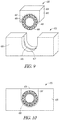
- FIG. 9 shows an exploded perspective view of a connector block 400, in accordance with one example; and FIG. 10 shows a side view of the connector block 400.
- the connector block 400 can include a metallic termination member 402, such as a metallic block 404.
- Metallic block 404 can include a partial block such that the metallic block 404 does not encircle a canted coil spring 406.
- the metallic block 404 can be a half-block, a 3/4-block, or a 1 ⁇ 4-block for example.
- the metallic block 404 can be formed by molding from stainless steel, MP35N, or other suitable metallic material. By forming the metallic block 404 as non-circumferential around coil spring 406, the metallic block 404 can be molded or sintered instead of machined, as required by circumferential connector blocks.
- the metallic block 404 can include an arched portion 407 including a coil spring receiving section 408.
- the coil spring receiving area 408 can include a groove 409.
- the connector block 400 can further include a connector block plastic housing portion 416 including a coil spring receiving section 418 formed integral with a plastic header core 420.
- the coil receiving section 418 can include a groove 419.
- the plastic housing portion 416 can be integrally formed as part of a connector block cavity of the header core 420 when the plastic header core 420 is molded.
- the plastic housing portion 416 can matingly receive the coil spring 408 and the metallic block 404.
- the coil spring receiving section 408 of the metallic block 404 and the coil spring receiving section 418 of the plastic housing portion 416 can be aligned to form a circumferential receiving section for the coil spring 406.
- the metallic block groove 409 can be aligned with the plastic housing portion grove 419 to define a circumferential groove to receive the coil spring 406.
- the metallic block 404 can be mounted within the plastic housing portion 416 and attached to the header core 420.
- a connector attachment can be made at an upper attachment surface 430 of the metallic block 404.
- FIG. 11 shows a side view of a connector block 502 connection to a feedthrough 512, in accordance with one example.
- the connector block 502 can include a connector block plastic housing 506 and a coil spring 508, such as discussed above.
- a metallic termination member 510 can include a flat ribbon connector and can be connected to the coil spring 508 and can extend to connect directly to the feedthrough 512 which communicates internally to housing 110.
- This structure eliminates having to weld a connector between the metallic termination member and the feedthrough 512. The single weld thus can reduce complexity and increase reliability compared to a two weld connection.
- An overmold 514 encapsulates the header core in this example.
- a pre-molded header can be utilized and the connector blocks can be covered by a medical adhesive sealant.
- FIG. 12 shows a perspective view of the implantable medical device 100, in accordance with one example.
- the implantable medical device 100 can include the header 120 mounted to the housing 110.
- the header 120 can include the header core 220 with the connector blocks 290 mounted into the connector block cavities of the header core 220.
- the connector blocks 290 can be formed as discussed above and side-loaded into the header core 220.
- one example can include placing a plastic connector block housing portion into a connector block cavity of a header, placing a coil spring into the connector block housing portion, and connecting a metallic termination member to the coil spring and positioning the metallic termination member to be exposed outside the plastic housing portion.
- the header core 220 can be encapsulated with an epoxy overmold 602.
Landscapes
- Health & Medical Sciences (AREA)
- Life Sciences & Earth Sciences (AREA)
- Engineering & Computer Science (AREA)
- Animal Behavior & Ethology (AREA)
- Radiology & Medical Imaging (AREA)
- Nuclear Medicine, Radiotherapy & Molecular Imaging (AREA)
- Biomedical Technology (AREA)
- General Health & Medical Sciences (AREA)
- Public Health (AREA)
- Veterinary Medicine (AREA)
- Biophysics (AREA)
- Heart & Thoracic Surgery (AREA)
- Manufacturing & Machinery (AREA)
- Electrotherapy Devices (AREA)
- Coupling Device And Connection With Printed Circuit (AREA)
Abstract
Description
- This application claims the benefit of priority under 35 U.S.C. § 119(e) of
U.S. Provisional Patent Application Serial Number 61/773,302, filed on March 6, 2013 - Implantable devices such as pacemakers or defibrillators include a housing and an attached header. The header includes one or more ports to receive a terminal end of an implantable lead. The header includes connector blocks with contacts that electrically communicate with terminal contacts on the lead. The connector block contacts are electrically connected to feedthroughs which contact electronics within the housing.
U.S. Pat. No. 5,076,270 discusses header contacts for an implantable device. -
- Example 1 can include subject matter that can include an apparatus comprising: an implantable housing; a header mounted to the implantable housing and including a connector block cavity; and a connector block located within the connector block cavity, the connector block including a plastic housing portion, a coil spring, and a metallic termination member connected to the coil spring and exposed outside the plastic housing portion.
- In Example 2, the subject matter of claim 1 can optionally include the metallic termination member being non-circumferential around the coil spring.
- In Example 3, the subject matter of any of Examples 1 or 2 can optionally include the connector block cavity being open on a side of the header such that the connector block is side-mounted into the header.
- In Example 4, the subject matter of any of Examples 1-3 can optionally include the plastic housing portion including a receiver section configured to receive at least a portion of the coil spring.
- In Example 5, the subject matter of any of Examples 1-4 can optionally include the plastic housing portion being integral to the header within the connector block cavity.
- In Example 6, the subject matter of any of Examples 1-4 can optionally include the plastic housing portion including a discrete plastic housing body mounted within the connector block cavity.
- In Example 7, the subject matter of any of Examples 1-4 or 6 can optionally include the metallic termination member including a flat ribbon connector.
- In Example 8, the subject matter of any of Examples 1-6 can optionally include the metallic termination member including a metallic block including at least a portion configured to receive the canted coil spring.
- In Example 9, the subject matter of any of Examples 1-4 or 6-8 can optionally include the plastic housing portion including a flat, planar outer surface with the flat connector ribbon lying flush against the flat, planar outer surface.
- In Example 10, the subject matter of any of Examples 1-4 or 6-8 can optionally include the plastic housing portion including a non-planar outer surface.
- In Example 11, the subject matter of any of Examples 1-4 or 6-8 can optionally include the metallic termination member including a flat ribbon connector which extends away from the connector block and connected directly to a feedthrough.
- In Example 12, the subject matter of any of Examples 1-11 can optionally include the header including a header core overmolded with an epoxy.
- Example 13 can include subject matter that can include an apparatus comprising: an implantable housing; a header mounted to the implantable housing and including a plastic header core having a connector block cavity; and a connector block located within the connector block cavity, the connector block including a plastic housing portion holding a spring and a metallic termination member connected to the spring and exposed outside the plastic housing portion; wherein the header core is overmolded with an epoxy to encapsulate the connector block and the header core.
- In Example 14, the subject matter of Example 13 can optionally include the metallic termination member being non-circumferential around the spring.
- In Example 15, the subject matter of any of Examples 13-14 can optionally include the plastic housing portion including a receiver section configured to receive at least a portion of the spring.
- In Example 16, the subject matter of any of Examples 13-15 can optionally include the plastic housing portion being integral to the header within the connector block cavity.
- In Example 17, the subject matter of any of Examples 15 can optionally include the plastic housing portion including a discrete plastic housing body mounted within the connector block cavity.
- Example 18 can include subject matter that can include a method comprising: placing a plastic connector block housing portion into a connector block cavity of a header; placing a coil spring into the connector block housing portion; and connecting a metallic termination member to the coil spring and positioning the metallic termination member to be exposed outside the plastic housing portion.
- In Example 19, the subject matter of Example 18 can optionally include the metallic termination member being non-circumferential around the coil spring.
- In Example 20, the subject matter of any of Examples 18 or 19 can optionally include overmolding the header with an epoxy.
- These examples can be combined in any permutation or combination. This overview is intended to provide an overview of subject matter of the present patent application. It is not intended to provide an exclusive or exhaustive explanation of the invention. The detailed description is included to provide further information about the present patent application.
- In the drawings, which are not necessarily drawn to scale, like numerals may describe similar components in different views. Like numerals having different letter suffixes may represent different instances of similar components. The drawings illustrate generally, by way of example, but not by way of limitation, various embodiments discussed in the present document.
-
FIG. 1 shows an implantable medical device in accordance with one example. -
FIG. 2 shows a perspective view of a header core for a header of an implantable medical device, in accordance with one example. -
FIG. 3 shows a perspective view of a connector block housing in accordance with one example. -
FIG. 4 shows a perspective view of a connector block in accordance with one example. -
FIG. 5 shows a perspective view of a termination member, in accordance with one example. -
FIG. 6 shows a perspective view of a termination member, in accordance with one example. -
FIG. 7A shows a perspective view of a connector block housing in accordance with one example. -
FIG. 7B shows a perspective view of a connector block housing in accordance with one example. -
FIG. 8A shows a perspective view of a connector block in accordance with one example. -
FIG. 8B shows a side cross-section view of the connector block ofFIG. 8A . -
FIG. 9 shows an exploded perspective view of a connector block, in accordance with one example. -
FIG. 10 shows a side view of the connector block ofFIG. 9 . -
FIG. 11 shows a side view of a connector block connection to a feedthrough, in accordance with one example. -
FIG. 12 shows a perspective view of an implantable medical device, in accordance with one example. -
FIG. 1 shows an implantablemedical device 100 in accordance with one example. The implantablemedical device 100 includes ametallic housing 110 and an attachedheader 120. Theheader 120 includes one ormore ports 122 to receive aterminal pin 124 of animplantable lead 130. Thelead 130 is configured to deliver pacing pulses, defibrillation shock energy, or cardioversion therapy to a heart, for example. The implantablemedical device 100 can be implanted in a surgically-formed pocket in a patient's chest or other desired location. The implantablemedical device 100 generally includes electronic components to perform signal analysis, processing, and control. The implantablemedical device 100 can include a power supply such as a battery, a capacitor, and other components housed withinhousing 110. The implantablemedical device 100 can include microprocessors to provide processing and evaluation to determine and deliver electrical shocks and pulses of different energy levels and timing for ventricular defibrillation, cardioversion, and pacing to a heart in response to cardiac arrhythmia including fibrillation, tachycardia, and bradycardia via one or more electrodes of thelead 130. -
FIG. 2 shows a perspective view of aheader core 220 for a header of an implantable medical device, in accordance with one example. Theheader core 220 can include acore body 225, formed of molded plastic, for example. Theheader core 220 can include one or bores 222 formed in theheader core body 225 to receive a terminal pin of a lead. Theheader core 220 can include one or moreconnector block cavities 230. Theconnector block cavities 230 can be open on aside surface 232 of theheader core 220. Theconnector block cavities 230 can be shaped and dimensioned to each receive aconnector block 290. Theconnector block 290 can be side-mounted into the side surface locatedconnector block cavities 230 of theheader core 220. Theconnector block 290 can be connected to feedthroughs that extend from the header into a housing of an implantable device. Thus, theconnector block 290 can receive a lead terminal pin and electrically couple the lead terminal pin to electronics within the housing via the feedthrough. -
FIG. 3 shows a perspective view of a connector blockplastic housing portion 260 in accordance with one example; andFIG. 4 shows a perspective view of theconnector block 290 in accordance with one example. - The
plastic housing portion 260 can include a discrete moldedplastic body 261 which is dimensioned to at least partially fit within the connector block cavity 230 (FIG. 2 ). Theplastic housing portion 260 can include abore 262 configured to receive a spring, such as acanted coil spring 280, therein. Theplastic housing portion 260 can include a coilspring receiving section 264, such as a race or groove 265 formed in the surface of theplastic housing portion 260 around the periphery of thebore 262. In other options, walls or other structures can be formed in thebore 262 to receive and hold thecoil spring 280. - The
plastic housing portion 260 can include aslot 266 which extends from thebore 262 to an exterior of theplastic housing portion 260. Theslot 266 can hold ametallic termination member 270 which extends from thecoil spring 262 to an exterior of theplastic housing portion 260. Themetallic termination member 270 can be formed of stainless steel, MP35N, or other suitable metallic materials. Themetallic termination member 270 can be connected to thecoil spring 280, extend through theslot 266 and be formed to lie flush on an exposedouter surface 263 of theplastic housing portion 260.Plastic housing portion 260 can include a flat, planar,outer surface 263. The flat, planarouter surface 263 provides for ease of further connections to themetallic termination member 270. -
FIG. 5 shows a perspective view of themetallic termination member 270, in accordance with one example. Themetallic termination member 270 can include aflat ribbon connector 294 formed by stamping, for example. The metallic termination member can include an L-shape with afirst end 296 to attach to the coil spring and anupper surface 298 for attachment of theconnector 294 to a feedthrough. -
FIG. 6 shows a perspective view of ametallic termination member 300, in accordance with one example. Themetallic termination member 300 can include aflat ribbon connector 302 formed by stamping, for example. Themetallic termination member 300 can include a curledportion 304 dimensioned to partially enclose thecoil spring 280. Themetallic termination member 300 can include a straight lead-outsection 305 and a flatupper connection surface 306. Themetallic termination member 300 can be mounted within the connector block plastic housing portion 260 (FIG. 3 ) such that the curledportion 304 is within thebore 262, the lead-outsection 305 extends through theslot 266 and the upper connections surface 306 lies flush against theouter surface 263 of theplastic housing portion 260. Thecoiled spring 280 is then mounted within the curledportion 304. - For each of the
metallic termination members metallic termination members coil spring 280. This allows for ease of manufacture and lower costs. Past block connectors included a canted coil spring mounted within a metallic housing having a race to circumferentially hold the spring. Forming such a circumferential metallic housing requires the metallic housing to be machined. In contrast, theplastic housing portion 260 ofconnector block 290 can be formed of molded plastic and themetallic termination members -
FIG. 7A shows a perspective view of a connector blockplastic housing portion 320 in accordance with one example. Theplastic housing portion 320 can include a molded plastic body and includes abore 322, a coilspring receiving section 324, and aslot 326 configured to receive thecoil spring 280 and themetallic termination member plastic housing portion 320 can include a non-planarouter surface 328. Non-planarouter surface 328 can include a rampedportion 329 or other shape configured to provide an easier connection surface for attaching a connector to the metallic termination member depending on the electronic configuration or feedthrough position of the implantable device. -
FIG. 7B shows a perspective view of a connector blockplastic housing portion 340 in accordance with one example. Theplastic housing portion 340 can include a molded plastic body and includes abore 342, a coilspring receiving section 344, and aslot 346 configured to receive thecoil spring 280 and themetallic termination member 270, 300 (FIG. 4 ). Theplastic housing portion 340 can include a non-planarouter surface 347. The non-planarouter surface 347 can include aprojection 348. Theprojection 348 can provide electrical insulation for themetallic termination member projection 348. -
FIG. 8A shows a perspective view of aconnector block 349 in accordance with one example; andFIG. 8B shows a side cross-section view of theconnector block 349. Theconnector block 349 includes a partially nested structure with aplastic housing portion 360 which is dimensioned to fit with ametallic termination member 350, both of which hold thecoil spring 280. Themetallic termination member 350 can be formed of stainless steel, MP35N, or other suitable metallic materials. Themetallic termination member 350 includes anupper surface 362 for attachment of connector to a feedthrough. -
FIG. 9 shows an exploded perspective view of aconnector block 400, in accordance with one example; andFIG. 10 shows a side view of theconnector block 400. - The
connector block 400 can include ametallic termination member 402, such as ametallic block 404.Metallic block 404 can include a partial block such that themetallic block 404 does not encircle a cantedcoil spring 406. Themetallic block 404 can be a half-block, a 3/4-block, or a ¼-block for example. Themetallic block 404 can be formed by molding from stainless steel, MP35N, or other suitable metallic material. By forming themetallic block 404 as non-circumferential aroundcoil spring 406, themetallic block 404 can be molded or sintered instead of machined, as required by circumferential connector blocks. Themetallic block 404 can include anarched portion 407 including a coilspring receiving section 408. The coilspring receiving area 408 can include agroove 409. - The
connector block 400 can further include a connector blockplastic housing portion 416 including a coilspring receiving section 418 formed integral with aplastic header core 420. Thecoil receiving section 418 can include agroove 419. Thus, theplastic housing portion 416 can be integrally formed as part of a connector block cavity of theheader core 420 when theplastic header core 420 is molded. Theplastic housing portion 416 can matingly receive thecoil spring 408 and themetallic block 404. The coilspring receiving section 408 of themetallic block 404 and the coilspring receiving section 418 of theplastic housing portion 416 can be aligned to form a circumferential receiving section for thecoil spring 406. In an example, themetallic block groove 409 can be aligned with the plastichousing portion grove 419 to define a circumferential groove to receive thecoil spring 406. Themetallic block 404 can be mounted within theplastic housing portion 416 and attached to theheader core 420. A connector attachment can be made at anupper attachment surface 430 of themetallic block 404. -
FIG. 11 shows a side view of aconnector block 502 connection to afeedthrough 512, in accordance with one example. Theconnector block 502 can include a connector blockplastic housing 506 and acoil spring 508, such as discussed above. Ametallic termination member 510 can include a flat ribbon connector and can be connected to thecoil spring 508 and can extend to connect directly to thefeedthrough 512 which communicates internally tohousing 110. This structure eliminates having to weld a connector between the metallic termination member and thefeedthrough 512. The single weld thus can reduce complexity and increase reliability compared to a two weld connection. Anovermold 514 encapsulates the header core in this example. In some embodiments, a pre-molded header can be utilized and the connector blocks can be covered by a medical adhesive sealant. -
FIG. 12 shows a perspective view of the implantablemedical device 100, in accordance with one example. The implantablemedical device 100 can include theheader 120 mounted to thehousing 110. Theheader 120 can include theheader core 220 with the connector blocks 290 mounted into the connector block cavities of theheader core 220. The connector blocks 290 can be formed as discussed above and side-loaded into theheader core 220. In forming a header with the connector block discussed herein, one example can include placing a plastic connector block housing portion into a connector block cavity of a header, placing a coil spring into the connector block housing portion, and connecting a metallic termination member to the coil spring and positioning the metallic termination member to be exposed outside the plastic housing portion. After all the connections have been made between the connector blocks 290 and the feedthroughs of thehousing 110, theheader core 220 can be encapsulated with anepoxy overmold 602. - The above detailed description includes references to the accompanying drawings, which form a part of the detailed description. The drawings show, by way of illustration, specific embodiments in which the invention can be practiced. These embodiments are also referred to herein as "examples." Such examples can include elements in addition to those shown or described. However, the present inventors also contemplate examples in which only those elements shown or described are provided. Moreover, the present inventors also contemplate examples using any combination or permutation of those elements shown or described (or one or more aspects thereof), either with respect to a particular example (or one or more aspects thereof), or with respect to other examples (or one or more aspects thereof) shown or described herein.
- All publications, patents, and patent documents referred to in this document are incorporated by reference herein in their entirety, as though individually incorporated by reference. In the event of inconsistent usages between this document and those documents so incorporated by reference, the usage in the incorporated reference(s) should be considered supplementary to that of this document; for irreconcilable inconsistencies, the usage in this document controls.
- In this document, the terms "a" or "an" are used, as is common in patent documents, to include one or more than one, independent of any other instances or usages of "at least one" or "one or more." In this document, the term "or" is used to refer to a nonexclusive or, such that "A or B" includes "A but not B," "B but not A," and "A and B," unless otherwise indicated. In the appended claims, the terms "including" and "in which" are used as the plain-English equivalents of the respective terms "comprising" and "wherein." Also, in the following claims, the terms "including" and "comprising" are open-ended, that is, a system, device, article, or process that includes elements in addition to those listed after such a term in a claim are still deemed to fall within the scope of that claim. Moreover, in the following claims, the terms "first," "second," and "third," etc. are used merely as labels, and are not intended to impose numerical requirements on their objects.
- Although the present invention is defined in the attached claims, it should be understood that the present invention can also (alternatively) be defined in accordance with the following embodiments:
- 1. An apparatus comprising:
- an implantable housing;
- a header mounted to the implantable housing and including a connector block cavity; and
- a connector block located within the connector block cavity, the connector block including a plastic housing portion, a coil spring, and a metallic termination member connected to the coil spring and exposed outside the plastic housing portion.
- 2. The apparatus of embodiment 1, wherein the metallic termination member is non-circumferential around the coil spring,
- 3. The apparatus of any of embodiments 1 -2, wherein the connector block cavity is open on a side of the header such that the connector block is side-mounted into the header.
- 4. The apparatus of any of embodiments 1-3, wherein the plastic housing portion includes a receiver section configured to receive at least a portion of the coil spring.
- 5. The apparatus of any of embodiments 1-4, wherein the plastic housing portion is integral to the header within the connector block cavity.
- 6. The apparatus of any of embodiments 1-4, wherein the plastic housing portion includes a discrete plastic housing body mounted within the connector block cavity.
- 7. The apparatus of any of embodiments 1-4 or 6, wherein the metallic termination member includes a flat ribbon connector.
- 8. The apparatus of any of embodiments 1-6, wherein the metallic termination member includes a metallic block including at least a portion configured to receive the coil spring.
- 9. The apparatus of any of embodiments 1-4 or 6-8, wherein the plastic housing portion includes a flat, planar outer surface with the fiat connector ribbon lying flush against the flat, planar outer surface.
- 10. The apparatus of any of embodiments 1-4 or 6-8, wherein the plastic housing portion includes a non-planar outer surface.
- 11. The apparatus of any of embodiments 1 -4 or 6-8, wherein the metallic termination member includes a flat ribbon connector which extends away from the connector block and connected directly to a feedthrough.
- 12. The apparatus of any of embodiments 1-11, wherein the header includes a header core overmolded with an epoxy.
- 13. An apparatus comprising:
- an implantable housing;
- a header mounted to the implantable housing and including a plastic header core having a connector block cavity; and
- a connector block located within the connector block cavity, the connector block including a plastic housing portion holding a spring and a metallic termination member connected to the spring and exposed outside the plastic housing portion;
- wherein the header core is overmolded with an epoxy to encapsulate the connector block and the header core.
- 14. The apparatus of embodiment 13, wherein the metallic termination member non-circumferential around the spring.
- 15. The apparatus of any of embodiments 13-14, wherein the plastic housing portion includes a receiver section configured to receive at least a portion of the spring.
- 16. The apparatus of any of embodiments 13-15, wherein the plastic housing portion is integral to the header within the connector block cavity.
- 17. The apparatus of any of embodiments 13-15, wherein the plastic housing portion includes a discrete plastic housing body mounted within the connector block cavity.
- 18. A method comprising:
- placing a plastic connector block housing portion into a connector block cavity of a header;
- placing a coil spring into the connector block housing portion; and connecting a metallic termination member to the coil spring and positioning the metallic termination member to be exposed outside the plastic housing portion.
- 19. The method of embodiment 18, wherein the metallic termination member is non-circumferential around the coil spring.
- 20. The method of any of embodiments 18 or 19, further including overmolding the header with an epoxy.
Claims (15)
- An apparatus comprising:an implantable housing (110);a header (120) mounted to the implantable housing and including a connector block cavity (230); anda connector block (290; 349) located within the connector block cavity, the connector block including a plastic housing portion (320; 340), a coil spring (280), and a metallic termination member (270; 300) connected to the coil spring and exposed outside the plastic housing portion,wherein the plastic housing portion includes a non-planar outer surface (328; 347)
- The apparatus of claim 1, wherein the non-planar outer surface (328) includes a ramped portion (329).
- The apparatus of claim 2, wherein the ramped portion is configured to provide an connection surface for attaching a connector to the metallic termination member.
- The apparatus of claim 1, wherein the non-planar outer surface (347) includes a projection (348).
- The apparatus of claim 4, wherein the projection 348 provides electrical insulation for the metallic termination member (270, 300) from wires running on the other side of the projection (348).
- The apparatus of claim 1, wherein the metallic termination member is non-circumferential around the coil spring.
- The apparatus of claim 1, wherein the connector block cavity is open on a side of the header such that the connector block is side-mounted into the header.
- The apparatus of claim 1, wherein the plastic housing portion includes a receiver section configured to receive at least a portion of the coil spring.
- The apparatus of claim 1, wherein the plastic housing portion includes a discrete plastic housing body mounted within the connector block cavity.
- The apparatus of claim 1, wherein the metallic termination member includes a flat ribbon connector.
- The apparatus of claim 1, wherein the metallic termination member includes a metallic block including at least a portion configured to receive the coil spring.
- The apparatus of claim 1, wherein the metallic termination member includes a flat ribbon connector which extends away from the connector block and connected directly to a feedthrough.
- The apparatus of claim 1, wherein the header includes a header core overmolded with an epoxy.
- A method comprising:placing a plastic connector block housing portion into a connector block cavity of a header;placing a coil spring into the connector block housing portion; andconnecting a metallic termination member to the coil spring and positioning the metallic termination member to be exposed outside the plastic housing portion,wherein the plastic housing portion includes a non-planar outer surface (328; 347.
- The method of claim 14, further including overmolding the header with an epoxy.
Applications Claiming Priority (3)
| Application Number | Priority Date | Filing Date | Title |
|---|---|---|---|
| US201361773302P | 2013-03-06 | 2013-03-06 | |
| PCT/US2014/018542 WO2014137684A2 (en) | 2013-03-06 | 2014-02-26 | Connector blocks for a header of an implantable device |
| EP14709153.2A EP2964320B1 (en) | 2013-03-06 | 2014-02-26 | Connector blocks for a header of an implantable device |
Related Parent Applications (1)
| Application Number | Title | Priority Date | Filing Date |
|---|---|---|---|
| EP14709153.2A Division EP2964320B1 (en) | 2013-03-06 | 2014-02-26 | Connector blocks for a header of an implantable device |
Publications (1)
| Publication Number | Publication Date |
|---|---|
| EP3598994A1 true EP3598994A1 (en) | 2020-01-29 |
Family
ID=50240098
Family Applications (2)
| Application Number | Title | Priority Date | Filing Date |
|---|---|---|---|
| EP14709153.2A Active EP2964320B1 (en) | 2013-03-06 | 2014-02-26 | Connector blocks for a header of an implantable device |
| EP19197735.4A Withdrawn EP3598994A1 (en) | 2013-03-06 | 2014-02-26 | Connector blocks for a header of an implantable device |
Family Applications Before (1)
| Application Number | Title | Priority Date | Filing Date |
|---|---|---|---|
| EP14709153.2A Active EP2964320B1 (en) | 2013-03-06 | 2014-02-26 | Connector blocks for a header of an implantable device |
Country Status (5)
| Country | Link |
|---|---|
| US (2) | US9345894B2 (en) |
| EP (2) | EP2964320B1 (en) |
| JP (1) | JP6154493B2 (en) |
| CN (1) | CN105025983B (en) |
| WO (1) | WO2014137684A2 (en) |
Families Citing this family (7)
| Publication number | Priority date | Publication date | Assignee | Title |
|---|---|---|---|---|
| EP2964320B1 (en) | 2013-03-06 | 2019-09-18 | Cardiac Pacemakers, Inc. | Connector blocks for a header of an implantable device |
| US9649500B2 (en) * | 2014-04-21 | 2017-05-16 | Medtronic, Inc. | Shield forming to facilitate tight radius at weld seam using progressive stamping |
| CN107658601A (en) * | 2017-10-26 | 2018-02-02 | 深圳市索诺瑞科技有限公司 | A kind of attachment structure of ultrasonic probe and ultrasonic image-forming system |
| US11559695B2 (en) | 2019-12-17 | 2023-01-24 | Medtronic, Inc. | Implantable medical devices having modular lead bores |
| EP3943031B1 (en) | 2020-07-24 | 2025-02-12 | Greatbatch Ltd. | Header connection system for implantable medical device |
| CN112604158B (en) * | 2020-12-11 | 2023-11-28 | 苏州景昱医疗器械有限公司 | Implantable medical devices and systems |
| CN115173108B (en) * | 2022-08-10 | 2024-12-03 | 景昱医疗科技(苏州)股份有限公司 | Connector, processing method and stimulation system |
Citations (5)
| Publication number | Priority date | Publication date | Assignee | Title |
|---|---|---|---|---|
| US5076270A (en) | 1990-05-03 | 1991-12-31 | Siemens-Pacesetter, Inc. | Apparatus and method for making electrical connections in an implantable pacemaker |
| US20040034393A1 (en) * | 2002-08-16 | 2004-02-19 | Cardiac Pacemakers, Inc. | Connector port construction technique for implantable medical device |
| WO2005081927A2 (en) * | 2004-02-23 | 2005-09-09 | Bal Seal Engineering Co., Inc. | Stackable assembly for direct connection between a pulse generator and a human body |
| WO2006026186A2 (en) * | 2004-08-26 | 2006-03-09 | Bal Seal Engineering Co., Inc. | Electrical conductive path for a medical electronics device |
| US20060224208A1 (en) * | 2005-04-05 | 2006-10-05 | Bal Seal Engineering Co., Inc. | Medical electronics electrical implantable medical devices |
Family Cites Families (31)
| Publication number | Priority date | Publication date | Assignee | Title |
|---|---|---|---|---|
| US3074046A (en) * | 1960-12-19 | 1963-01-15 | Cons Engineering Service Inc | Coiled wire nut fastener and conductor |
| US4352531A (en) * | 1980-06-02 | 1982-10-05 | Amp Incorporated | Commoning element for an electrical connector |
| US4655462A (en) | 1985-01-07 | 1987-04-07 | Peter J. Balsells | Canted coiled spring and seal |
| US4838815A (en) * | 1986-09-26 | 1989-06-13 | Hosiden Electronics Co., Ltd. | Connector assembly |
| US4848346A (en) * | 1987-12-02 | 1989-07-18 | Siemens-Pacesetter, Inc. | Pacemaker connector system |
| US5235742A (en) | 1989-11-20 | 1993-08-17 | Siemens Pacesetter, Inc. | Method of making an implantable device |
| US5067903A (en) | 1989-11-20 | 1991-11-26 | Siemens-Pacesetter, Inc. | Ribbon conductor set and method |
| US5012807A (en) | 1990-05-03 | 1991-05-07 | Siemens-Pacesetter, Inc. | Multi-part molded pacemaker connector and method of making same |
| US6205358B1 (en) | 1997-08-01 | 2001-03-20 | Medtronic, Inc. | Method of making ultrasonically welded, staked of swaged components in an implantable medical device |
| US6183305B1 (en) * | 1998-12-04 | 2001-02-06 | Pacesetter, Inc. | High strength connector design for passive fixation pacing lead |
| WO2003071635A1 (en) | 2002-02-15 | 2003-08-28 | Bal Seal Engineering Co., Inc. | Medically implantable electrical connector with constant conductivity |
| US6895276B2 (en) * | 2002-02-28 | 2005-05-17 | Medtronic, Inc. | In-line lead header for an implantable medical device |
| US6862478B1 (en) | 2002-06-14 | 2005-03-01 | Pacesetter, Inc. | Connector top for implantable medical device |
| US7274963B2 (en) | 2002-12-16 | 2007-09-25 | Cardiac Pacemakers, Inc. | Interconnect for implantable medical device header |
| US7110827B2 (en) | 2003-04-25 | 2006-09-19 | Medtronic, Inc. | Electrical connectors for medical lead having weld-less wiring connection |
| US6878013B1 (en) | 2003-12-02 | 2005-04-12 | Edgar G. Behan | Connector apparatus for a medical device |
| US7083474B1 (en) * | 2004-12-08 | 2006-08-01 | Pacesetter, Inc. | System for lead retention and sealing of an implantable medical device |
| CN101132829A (en) | 2005-01-18 | 2008-02-27 | 巴尔密封工程有限公司 | Solder plate contacts for implantable medical devices |
| CN101175528A (en) * | 2005-04-05 | 2008-05-07 | 巴尔密封工程有限公司 | Medical electronic and electrical implantable medical device |
| US7316593B2 (en) * | 2005-05-19 | 2008-01-08 | Bal Seal Engineering Co., Inc. | Electrical connector with embedded canted coil spring |
| US7654843B2 (en) | 2006-02-28 | 2010-02-02 | Medtronic, Inc. | Connector assembly with internal seals and manufacturing method |
| CN201029131Y (en) * | 2007-03-02 | 2008-02-27 | 富士康(昆山)电脑接插件有限公司 | electrical connector terminal |
| US7914351B2 (en) * | 2007-04-13 | 2011-03-29 | Bal Seal Engineering | Electrical connectors with improved electrical contact performance |
| US7690953B2 (en) | 2007-05-03 | 2010-04-06 | Deringer-Ney, Inc. | Stackable electrical connection apparatus |
| WO2011017432A1 (en) * | 2009-08-05 | 2011-02-10 | Medtronic, Inc. | Connector and contact assemblies for medical devices |
| US8731671B2 (en) | 2010-08-25 | 2014-05-20 | Cardiac Pacemakers, Inc. | Header contact for an implantable device |
| US20120089203A1 (en) * | 2010-10-12 | 2012-04-12 | Advanced Neuromodulation Systems, Inc. | Electrical connections for use in implantable medical devices |
| US8735751B2 (en) * | 2011-04-26 | 2014-05-27 | Bal Seal Engineering, Inc. | Varying diameter canted coil spring contacts and related methods of forming |
| US20130096366A1 (en) | 2011-10-12 | 2013-04-18 | Wim Bervoets | Implantable medical device |
| EP2964320B1 (en) | 2013-03-06 | 2019-09-18 | Cardiac Pacemakers, Inc. | Connector blocks for a header of an implantable device |
| WO2014186330A1 (en) | 2013-05-13 | 2014-11-20 | Cardiac Pacemakers, Inc. | Header connection with reduced complexity |
-
2014
- 2014-02-26 EP EP14709153.2A patent/EP2964320B1/en active Active
- 2014-02-26 JP JP2015561394A patent/JP6154493B2/en not_active Expired - Fee Related
- 2014-02-26 EP EP19197735.4A patent/EP3598994A1/en not_active Withdrawn
- 2014-02-26 WO PCT/US2014/018542 patent/WO2014137684A2/en not_active Ceased
- 2014-02-26 CN CN201480012223.8A patent/CN105025983B/en not_active Expired - Fee Related
- 2014-02-26 US US14/190,405 patent/US9345894B2/en active Active
-
2016
- 2016-05-12 US US15/152,774 patent/US10232186B2/en active Active
Patent Citations (5)
| Publication number | Priority date | Publication date | Assignee | Title |
|---|---|---|---|---|
| US5076270A (en) | 1990-05-03 | 1991-12-31 | Siemens-Pacesetter, Inc. | Apparatus and method for making electrical connections in an implantable pacemaker |
| US20040034393A1 (en) * | 2002-08-16 | 2004-02-19 | Cardiac Pacemakers, Inc. | Connector port construction technique for implantable medical device |
| WO2005081927A2 (en) * | 2004-02-23 | 2005-09-09 | Bal Seal Engineering Co., Inc. | Stackable assembly for direct connection between a pulse generator and a human body |
| WO2006026186A2 (en) * | 2004-08-26 | 2006-03-09 | Bal Seal Engineering Co., Inc. | Electrical conductive path for a medical electronics device |
| US20060224208A1 (en) * | 2005-04-05 | 2006-10-05 | Bal Seal Engineering Co., Inc. | Medical electronics electrical implantable medical devices |
Also Published As
| Publication number | Publication date |
|---|---|
| EP2964320B1 (en) | 2019-09-18 |
| WO2014137684A2 (en) | 2014-09-12 |
| US20140256184A1 (en) | 2014-09-11 |
| US10232186B2 (en) | 2019-03-19 |
| JP6154493B2 (en) | 2017-06-28 |
| WO2014137684A3 (en) | 2014-10-30 |
| CN105025983B (en) | 2017-04-26 |
| CN105025983A (en) | 2015-11-04 |
| US20160250482A1 (en) | 2016-09-01 |
| US9345894B2 (en) | 2016-05-24 |
| EP2964320A2 (en) | 2016-01-13 |
| JP2016508829A (en) | 2016-03-24 |
Similar Documents
| Publication | Publication Date | Title |
|---|---|---|
| US10232186B2 (en) | Method of forming connector blocks for a header of an implantable device | |
| CN105492069B (en) | With improved conductive electrical communication without lead pacemaker | |
| EP3359254B1 (en) | Connector block assembly | |
| US8604341B2 (en) | Feedthrough assembly for an implantable device | |
| EP1998851B1 (en) | Feedthrough connector for implantable device | |
| US7650191B1 (en) | Implantable medical device having a header with an integrated telemetry coil | |
| JP6640256B2 (en) | Implantable medical device | |
| US20040034393A1 (en) | Connector port construction technique for implantable medical device | |
| US20060089680A1 (en) | Welded connector attachment | |
| US20090118779A1 (en) | Modular System For A Wireless Implantable Device | |
| US20140336735A1 (en) | Header connection with reduced complexity | |
| US20240222852A1 (en) | Retention features for antenna | |
| US20240216702A1 (en) | Header interconnect wire support | |
| US20250381413A1 (en) | Feedthrough support features | |
| US20240226584A1 (en) | Header index locking bore assembly | |
| US20240216700A1 (en) | Header composit bore for reduced lead insertion force | |
| US20060241715A1 (en) | Electrode for a pulse generator and method therefor | |
| EP4259271B1 (en) | Electrical component for an implantable medical device | |
| US10828496B2 (en) | Core-clip PG-lead spring electrical contact |
Legal Events
| Date | Code | Title | Description |
|---|---|---|---|
| PUAI | Public reference made under article 153(3) epc to a published international application that has entered the european phase |
Free format text: ORIGINAL CODE: 0009012 |
|
| STAA | Information on the status of an ep patent application or granted ep patent |
Free format text: STATUS: REQUEST FOR EXAMINATION WAS MADE |
|
| 17P | Request for examination filed |
Effective date: 20190917 |
|
| AC | Divisional application: reference to earlier application |
Ref document number: 2964320 Country of ref document: EP Kind code of ref document: P |
|
| AK | Designated contracting states |
Kind code of ref document: A1 Designated state(s): AL AT BE BG CH CY CZ DE DK EE ES FI FR GB GR HR HU IE IS IT LI LT LU LV MC MK MT NL NO PL PT RO RS SE SI SK SM TR |
|
| STAA | Information on the status of an ep patent application or granted ep patent |
Free format text: STATUS: THE APPLICATION IS DEEMED TO BE WITHDRAWN |
|
| 18D | Application deemed to be withdrawn |
Effective date: 20200730 |