EP3598936A1 - Physiological information measurement device and method for outputting data for displaying physiological information - Google Patents
Physiological information measurement device and method for outputting data for displaying physiological information Download PDFInfo
- Publication number
- EP3598936A1 EP3598936A1 EP19187470.0A EP19187470A EP3598936A1 EP 3598936 A1 EP3598936 A1 EP 3598936A1 EP 19187470 A EP19187470 A EP 19187470A EP 3598936 A1 EP3598936 A1 EP 3598936A1
- Authority
- EP
- European Patent Office
- Prior art keywords
- time
- physiological information
- averaged value
- time period
- graph curve
- Prior art date
- Legal status (The legal status is an assumption and is not a legal conclusion. Google has not performed a legal analysis and makes no representation as to the accuracy of the status listed.)
- Granted
Links
Images


Classifications
-
- A—HUMAN NECESSITIES
- A61—MEDICAL OR VETERINARY SCIENCE; HYGIENE
- A61B—DIAGNOSIS; SURGERY; IDENTIFICATION
- A61B5/00—Measuring for diagnostic purposes; Identification of persons
- A61B5/72—Signal processing specially adapted for physiological signals or for diagnostic purposes
- A61B5/7225—Details of analogue processing, e.g. isolation amplifier, gain or sensitivity adjustment, filtering, baseline or drift compensation
-
- A—HUMAN NECESSITIES
- A61—MEDICAL OR VETERINARY SCIENCE; HYGIENE
- A61B—DIAGNOSIS; SURGERY; IDENTIFICATION
- A61B5/00—Measuring for diagnostic purposes; Identification of persons
- A61B5/145—Measuring characteristics of blood in vivo, e.g. gas concentration or pH-value ; Measuring characteristics of body fluids or tissues, e.g. interstitial fluid or cerebral tissue
- A61B5/1455—Measuring characteristics of blood in vivo, e.g. gas concentration or pH-value ; Measuring characteristics of body fluids or tissues, e.g. interstitial fluid or cerebral tissue using optical sensors, e.g. spectral photometrical oximeters
- A61B5/14551—Measuring characteristics of blood in vivo, e.g. gas concentration or pH-value ; Measuring characteristics of body fluids or tissues, e.g. interstitial fluid or cerebral tissue using optical sensors, e.g. spectral photometrical oximeters for measuring blood gases
-
- A—HUMAN NECESSITIES
- A61—MEDICAL OR VETERINARY SCIENCE; HYGIENE
- A61B—DIAGNOSIS; SURGERY; IDENTIFICATION
- A61B5/00—Measuring for diagnostic purposes; Identification of persons
- A61B5/72—Signal processing specially adapted for physiological signals or for diagnostic purposes
- A61B5/7221—Determining signal validity, reliability or quality
-
- A—HUMAN NECESSITIES
- A61—MEDICAL OR VETERINARY SCIENCE; HYGIENE
- A61B—DIAGNOSIS; SURGERY; IDENTIFICATION
- A61B5/00—Measuring for diagnostic purposes; Identification of persons
- A61B5/72—Signal processing specially adapted for physiological signals or for diagnostic purposes
- A61B5/7271—Specific aspects of physiological measurement analysis
- A61B5/7275—Determining trends in physiological measurement data; Predicting development of a medical condition based on physiological measurements, e.g. determining a risk factor
-
- A—HUMAN NECESSITIES
- A61—MEDICAL OR VETERINARY SCIENCE; HYGIENE
- A61B—DIAGNOSIS; SURGERY; IDENTIFICATION
- A61B5/00—Measuring for diagnostic purposes; Identification of persons
- A61B5/74—Details of notification to user or communication with user or patient; User input means
- A61B5/742—Details of notification to user or communication with user or patient; User input means using visual displays
-
- G—PHYSICS
- G16—INFORMATION AND COMMUNICATION TECHNOLOGY [ICT] SPECIALLY ADAPTED FOR SPECIFIC APPLICATION FIELDS
- G16H—HEALTHCARE INFORMATICS, i.e. INFORMATION AND COMMUNICATION TECHNOLOGY [ICT] SPECIALLY ADAPTED FOR THE HANDLING OR PROCESSING OF MEDICAL OR HEALTHCARE DATA
- G16H50/00—ICT specially adapted for medical diagnosis, medical simulation or medical data mining; ICT specially adapted for detecting, monitoring or modelling epidemics or pandemics
- G16H50/30—ICT specially adapted for medical diagnosis, medical simulation or medical data mining; ICT specially adapted for detecting, monitoring or modelling epidemics or pandemics for calculating health indices; for individual health risk assessment
Definitions
- the presently disclosed subject matter relates to a device for displaying physiological information of a subject and a method for outputting data for displaying the physiological information.
- JP-A-2015-107229 discloses a device for displaying physiological information.
- various sets of physiological information of a subject are displayed as numerical values.
- a displayed numerical value corresponds to a result which is obtained by performing a time-averaging process on time-varying values of physiological information for a predetermined time period.
- the amount of a temporal change of the values of physiological information may be used as an index indicating the instability of physiological information (i.e., the condition of the subject).
- the amount of a temporal change of physiological information (the level of variation from the displayed value) may not be recognized from the displayed value itself which is obtained through a time-averaging process.
- the presently disclosed subject matter is to assist a user to accurately recognize the condition of the subject.
- a physiological information measurement device including:
- a method for outputting data for displaying physiological information including:
- the user can check, through the display, time changes of a plurality of time-averaged values which are calculated from the same physiological information that is acquired from the subject, for respective different time periods.
- a graph curve indicating a temporal change of a time-averaged value which is calculated for a shorter time period reflects more strongly the variation of acquired physiological information. Therefore, when the consistency between the first and second graph curves is low, it is indicated that the physiological information of the subject is unstable. That is, the user can recognize, through the display, not only the time-averaged value of the physiological information of the subject, but also the stability of the physiological information. Therefore, it is possible to assist the user to accurately recognize the condition of the subject.
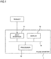
- FIG. 1 illustrates the functional configuration of a pulse oximeter 1 according to an exemplary embodiment.
- the pulse oximeter 1 may include an input interface 11, one or more processors 12, a display 13, and a bus 14.
- the bus 14 interconnects the input interface 11, the processor 12, and the display 13 such that signals and data can be exchanged between these components.
- a probe (not illustrated) is attached to the fingertip or earlobe of a subject.
- the probe may include a light emitter and a light detector.
- the light emitter emits a red light beam and an infrared light beam.
- the light detector outputs a signal corresponding to the amounts of the red and infrared light beams which are transmitted through or reflected from a portion where the probe is attached.
- the signal is supplied to the input interface 11.
- the input interface 11 may include an appropriate circuit configuration that can convert the supplied signals to data on which the processor 12 can execute a process illustrated in FIG. 2 .
- the processor 12 is configured to calculate at least the transcutaneous arterial oxygen saturation (SpO2) of the subject based on the data which are supplied through the input interface 11 (STEP 1).
- the method for calculating the SpO2 is known, and therefore, its detailed description will be omitted.
- the SpO2 is an example of the physiological information
- the calculation of the SpO2 is an example of acquiring of the physiological information.
- the calculation of the SpO2 is performed every predetermined time period. For example, the predetermined time period is one second.
- the processor 12 calculates a first time-averaged value A1 of the SpO2 for a first time period T1 (STEP 2). Specifically, the average value of a plurality of the SpO2 values which are calculated during a time period of the first time period T1 before the present time is calculated. For example, the first time period T1 is 10 seconds.
- the time-varying SpO2 is expressed as f(t)
- the first time-averaged value A1(T0) at the present time t0 can be indicated by the following expression.
- a 1 to 1 T 1 ⁇ t 0 ⁇ T 1 t 0 f t dt
- the processor 12 Every time when the SpO2 is calculated, the processor 12 further calculates a second time-averaged value A2 of the SpO2 for a second time period T2 (STEP 3). Specifically, the average value of a plurality of the SpO2 values which are calculated during a time period of the second time period T2 before the present time is calculated.
- the second time period T2 is different from the first time period T1.
- the second time period T2 is three seconds.
- the time-varying SpO2 is expressed as f(t)
- the second time-averaged value A2(t0) at the present time t0 can be indicated by the following expression.
- a 2 to 1 T 2 ⁇ to ⁇ T 2 t 0 f t dt
- STEP 2 and STEP 3 may be conducted in the reverse order or at the same time.
- the processor 12 outputs data for displaying the first and second time-averaged values A1, A2 of the SpO2 on the display 13.
- the display 13 displays the first and second time-averaged values A1, A2 based on the data supplied from the processor 12 (STEP 4).
- each of the first and second time-averaged values A1, A2 is indicated by a point in the graph curve illustrated in FIG. 3 .
- the first time-averaged value A1 is indicated by black circles
- the second time-averaged value A2 is indicated by white squares.
- a first graph curve G1 indicating a temporal change of the first time-averaged value A1 and a second graph curve G2 indicating a temporal change of the second time-averaged value A2 are displayed on the display 13. At least the latest first time-averaged value A1 may be displayed also as a numerical value.
- the user can check, through the display 13, time changes of a plurality of time-averaged values which are calculated from the SpO2 that is acquired from the same subject, for respective different time periods.
- the second graph curve G2 indicating a temporal change of the second time-averaged value A2 which is calculated for the shorter second time period T2 reflects more strongly the variation of the acquired SpO2. Therefore, when the consistency between the first graph curve G1 and the second graph curve G2 is low, it is indicated that the SpO2 of the subject is unstable. In the example illustrated in FIG. 3 , for example, the consistency between the first graph curve G1 and the second graph curve G2 becomes higher as time passes. Therefore, it is recognized that the SpO2 of the subject is gradually stabilized.
- the user can recognize not only the time-averaged value of the SpO2 of the subject, but also the stability of the SpO2, through the display 13. Therefore, it is possible to assist the user to accurately recognize the condition of the subject.
- the one or more regions which is located between the first graph curve G1 and the second graph curve G2 may be displayed in a color that is different from the background color of the display 13.
- the above-described function of the processor 12 may be realized by a general-purpose microprocessor which operates in cooperation with one or more memory, or by a dedicated integrated circuit such as a microcontroller, an FPGA (Field Programmable Gate Array) or an ASIC (Application Specific Integrated Circuit).
- a general-purpose microprocessor which operates in cooperation with one or more memory, or by a dedicated integrated circuit such as a microcontroller, an FPGA (Field Programmable Gate Array) or an ASIC (Application Specific Integrated Circuit).
- each of the first time-averaged value A1 and the second time-averaged value A2 is calculated as a simple average value.
- at least one of the first time-averaged value A1 and the second time-averaged value A2 may be acquired as the intermediate value or mode value of a plurality of SpO2 values which are acquired during a corresponding time period before the present time.
- the first and second graph curves are displayed on the display.
- the first and second graph curves may be output (printed) on a sheet.
- data for displaying the first and second graph curves may be output to an external device such as a smartphone. According to this configuration, the first and second graph curves can be checked on a display of the external device.
- the configuration which has been described above with reference to the exemplary embodiment can be applied to arbitrary physiological information which can be acquired from a subject and which involves time changes.
Landscapes
- Health & Medical Sciences (AREA)
- Life Sciences & Earth Sciences (AREA)
- Engineering & Computer Science (AREA)
- Physics & Mathematics (AREA)
- Medical Informatics (AREA)
- Public Health (AREA)
- General Health & Medical Sciences (AREA)
- Biomedical Technology (AREA)
- Pathology (AREA)
- Surgery (AREA)
- Animal Behavior & Ethology (AREA)
- Veterinary Medicine (AREA)
- Molecular Biology (AREA)
- Heart & Thoracic Surgery (AREA)
- Biophysics (AREA)
- Signal Processing (AREA)
- Computer Vision & Pattern Recognition (AREA)
- Artificial Intelligence (AREA)
- Psychiatry (AREA)
- Physiology (AREA)
- Power Engineering (AREA)
- Spectroscopy & Molecular Physics (AREA)
- Optics & Photonics (AREA)
- Data Mining & Analysis (AREA)
- Primary Health Care (AREA)
- Databases & Information Systems (AREA)
- Epidemiology (AREA)
- Measurement Of The Respiration, Hearing Ability, Form, And Blood Characteristics Of Living Organisms (AREA)
- Measuring And Recording Apparatus For Diagnosis (AREA)
Abstract
Description
- This application is based on Japanese Patent Application No.
2018-139512 filed on July 25, 2018 - The presently disclosed subject matter relates to a device for displaying physiological information of a subject and a method for outputting data for displaying the physiological information.
-
JP-A-2015-107229 - The amount of a temporal change of the values of physiological information may be used as an index indicating the instability of physiological information (i.e., the condition of the subject). However, the amount of a temporal change of physiological information (the level of variation from the displayed value) may not be recognized from the displayed value itself which is obtained through a time-averaging process.
- Accordingly, the presently disclosed subject matter is to assist a user to accurately recognize the condition of the subject.
- According to a first aspect of the presently disclosed subject matter, there is provided a physiological information measurement device including:
- one or more processors configured to calculate a first time-averaged value of physiological information of a subject for a first time period and calculate a second time-averaged value of the physiological information for a second time period that is different from the first time period; and
- a display configured to display a first graph curve indicating a temporal change of the first time-averaged value and a second graph curve indicating a temporal change of the second time-averaged value.
- According to a second aspect of the presently disclosed subject matter, there is provided a method for outputting data for displaying physiological information, the method including:
- acquiring physiological information of a subject;
- calculating a first time-averaged value of the physiological information for a first time period;
- calculating a second time-averaged value of the physiological information for a second time period that is different from the first time period; and
- outputting data for displaying a first graph curve indicating a temporal change of the first time-averaged value and a second graph curve indicating a temporal change of the second time-averaged value.
- According to the above-described configuration, the user can check, through the display, time changes of a plurality of time-averaged values which are calculated from the same physiological information that is acquired from the subject, for respective different time periods. A graph curve indicating a temporal change of a time-averaged value which is calculated for a shorter time period reflects more strongly the variation of acquired physiological information. Therefore, when the consistency between the first and second graph curves is low, it is indicated that the physiological information of the subject is unstable. That is, the user can recognize, through the display, not only the time-averaged value of the physiological information of the subject, but also the stability of the physiological information. Therefore, it is possible to assist the user to accurately recognize the condition of the subject.
-
-
FIG. 1 illustrates the functional configuration of a pulse oximeter according to an exemplary embodiment. -
FIG. 2 illustrates the procedure of a process which is performed by the pulse oximeter ofFIG. 1 . -
FIG. 3 illustrates a display example of a display of the pulse oximeter ofFIG. 1 . -
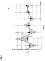
FIG. 4 illustrates another display example of the display of the pulse oximeter ofFIG. 1 . - Hereinafter, an exemplary embodiment will be described in detail with reference to the accompanying drawings.
FIG. 1 illustrates the functional configuration of apulse oximeter 1 according to an exemplary embodiment. - The
pulse oximeter 1 may include aninput interface 11, one ormore processors 12, adisplay 13, and abus 14. Thebus 14 interconnects theinput interface 11, theprocessor 12, and thedisplay 13 such that signals and data can be exchanged between these components. - A probe (not illustrated) is attached to the fingertip or earlobe of a subject. The probe may include a light emitter and a light detector. The light emitter emits a red light beam and an infrared light beam. The light detector outputs a signal corresponding to the amounts of the red and infrared light beams which are transmitted through or reflected from a portion where the probe is attached. The signal is supplied to the
input interface 11. Theinput interface 11 may include an appropriate circuit configuration that can convert the supplied signals to data on which theprocessor 12 can execute a process illustrated inFIG. 2 . - The
processor 12 is configured to calculate at least the transcutaneous arterial oxygen saturation (SpO2) of the subject based on the data which are supplied through the input interface 11 (STEP 1). The method for calculating the SpO2 is known, and therefore, its detailed description will be omitted. The SpO2 is an example of the physiological information, and the calculation of the SpO2 is an example of acquiring of the physiological information. The calculation of the SpO2 is performed every predetermined time period. For example, the predetermined time period is one second. - Every time when the SpO2 is calculated, the
processor 12 calculates a first time-averaged value A1 of the SpO2 for a first time period T1 (STEP 2). Specifically, the average value of a plurality of the SpO2 values which are calculated during a time period of the first time period T1 before the present time is calculated. For example, the first time period T1 is 10 seconds. When the time-varying SpO2 is expressed as f(t), the first time-averaged value A1(T0) at the present time t0 can be indicated by the following expression.
- Every time when the SpO2 is calculated, the
processor 12 further calculates a second time-averaged value A2 of the SpO2 for a second time period T2 (STEP 3). Specifically, the average value of a plurality of the SpO2 values which are calculated during a time period of the second time period T2 before the present time is calculated. The second time period T2 is different from the first time period T1. For example, the second time period T2 is three seconds. When the time-varying SpO2 is expressed as f(t), the second time-averaged value A2(t0) at the present time t0 can be indicated by the following expression.
- STEP 2 and STEP 3 may be conducted in the reverse order or at the same time.
- Then, the
processor 12 outputs data for displaying the first and second time-averaged values A1, A2 of the SpO2 on thedisplay 13. Thedisplay 13 displays the first and second time-averaged values A1, A2 based on the data supplied from the processor 12 (STEP 4). - For example, each of the first and second time-averaged values A1, A2 is indicated by a point in the graph curve illustrated in
FIG. 3 . InFIG. 3 , the first time-averaged value A1 is indicated by black circles, and the second time-averaged value A2 is indicated by white squares. - Then, the process returns to
STEP 1, and the above-described process is periodically repeated. Accordingly, as illustrated inFIG. 3 , a first graph curve G1 indicating a temporal change of the first time-averaged value A1 and a second graph curve G2 indicating a temporal change of the second time-averaged value A2 are displayed on thedisplay 13. At least the latest first time-averaged value A1 may be displayed also as a numerical value. - According to the above-described configuration, the user can check, through the
display 13, time changes of a plurality of time-averaged values which are calculated from the SpO2 that is acquired from the same subject, for respective different time periods. The second graph curve G2 indicating a temporal change of the second time-averaged value A2 which is calculated for the shorter second time period T2 reflects more strongly the variation of the acquired SpO2. Therefore, when the consistency between the first graph curve G1 and the second graph curve G2 is low, it is indicated that the SpO2 of the subject is unstable. In the example illustrated inFIG. 3 , for example, the consistency between the first graph curve G1 and the second graph curve G2 becomes higher as time passes. Therefore, it is recognized that the SpO2 of the subject is gradually stabilized. - That is, the user can recognize not only the time-averaged value of the SpO2 of the subject, but also the stability of the SpO2, through the
display 13. Therefore, it is possible to assist the user to accurately recognize the condition of the subject. - As illustrated in
FIG. 4 , the one or more regions which is located between the first graph curve G1 and the second graph curve G2 may be displayed in a color that is different from the background color of thedisplay 13. - According to the above-described configuration, it is recognized that the larger the areas of the regions which are displayed in the different color, the higher the inconsistency between the first graph curve G1 and the second graph curve G2, and the lower the stability of the SpO2 value. Therefore, a change in condition of the subject can be recognized more intuitively.
- The above-described function of the
processor 12 may be realized by a general-purpose microprocessor which operates in cooperation with one or more memory, or by a dedicated integrated circuit such as a microcontroller, an FPGA (Field Programmable Gate Array) or an ASIC (Application Specific Integrated Circuit). - The above-described exemplary embodiment is a mere example for facilitating understanding of the presently disclosed subject matter. The configuration of the exemplary embodiment may be appropriately changed or improved without departing from the spirit of the presently disclosed subject matter.
- In the above-described exemplary embodiment, each of the first time-averaged value A1 and the second time-averaged value A2 is calculated as a simple average value. However, at least one of the first time-averaged value A1 and the second time-averaged value A2 may be acquired as the intermediate value or mode value of a plurality of SpO2 values which are acquired during a corresponding time period before the present time.
- In the above-described embodiment, the first and second graph curves are displayed on the display. However, the first and second graph curves may be output (printed) on a sheet. Alternatively, data for displaying the first and second graph curves may be output to an external device such as a smartphone. According to this configuration, the first and second graph curves can be checked on a display of the external device.
- The configuration which has been described above with reference to the exemplary embodiment can be applied to arbitrary physiological information which can be acquired from a subject and which involves time changes.
Claims (3)
- A physiological information measurement device comprising:one or more processors configured to calculate a first time-averaged value of physiological information of a subject based for a first time period and calculate a second time-averaged value of the physiological information for a second time period that is different from the first time period; anda display configured to display a first graph curve indicating a temporal change of the first time-averaged value and a second graph curve indicating a temporal change of the second time-averaged value.
- The physiological information measurement device according to claim 1,
wherein a region which is located between the first graph curve and the second graph curve is displayed by a color that is different from a background color of the display. - A method for outputting data for displaying physiological information, the method comprising:acquiring physiological information of a subject;calculating a first time-averaged value of the physiological information for a first time period;calculating a second time-averaged value of the physiological information for a second time period that is different from the first time period; andoutputting data for displaying a first graph curve indicating a temporal change of the first time-averaged value and a second graph curve indicating a temporal change of the second time-averaged value.
Applications Claiming Priority (1)
| Application Number | Priority Date | Filing Date | Title |
|---|---|---|---|
| JP2018139512A JP2020014665A (en) | 2018-07-25 | 2018-07-25 | Biological information display device and method for outputting data for displaying biological information |
Publications (2)
| Publication Number | Publication Date |
|---|---|
| EP3598936A1 true EP3598936A1 (en) | 2020-01-29 |
| EP3598936B1 EP3598936B1 (en) | 2024-11-06 |
Family
ID=67438319
Family Applications (1)
| Application Number | Title | Priority Date | Filing Date |
|---|---|---|---|
| EP19187470.0A Active EP3598936B1 (en) | 2018-07-25 | 2019-07-22 | Physiological information measurement device and method for outputting data for displaying physiological information |
Country Status (3)
| Country | Link |
|---|---|
| US (1) | US20200029913A1 (en) |
| EP (1) | EP3598936B1 (en) |
| JP (1) | JP2020014665A (en) |
Citations (3)
| Publication number | Priority date | Publication date | Assignee | Title |
|---|---|---|---|---|
| US20110004085A1 (en) * | 2009-04-30 | 2011-01-06 | Dexcom, Inc. | Performance reports associated with continuous sensor data from multiple analysis time periods |
| US20110196213A1 (en) * | 2009-06-26 | 2011-08-11 | Roche Diagnostics Operations, Inc. | Display For Biological Values |
| JP2015107229A (en) | 2013-12-04 | 2015-06-11 | 日本光電工業株式会社 | Biosignal measuring system |
Family Cites Families (3)
| Publication number | Priority date | Publication date | Assignee | Title |
|---|---|---|---|---|
| EP1918837A1 (en) * | 2006-10-31 | 2008-05-07 | F. Hoffmann-La Roche AG | Method for processing a chronological sequence of measurements of a time dependent parameter |
| US20090088606A1 (en) * | 2007-09-28 | 2009-04-02 | Cuddihy Paul E | Systems and methods for patient specific adaptable telemonitoring alerts |
| WO2016132529A1 (en) * | 2015-02-20 | 2016-08-25 | 楽天株式会社 | Information processing device, information processing method, and information processing program |
-
2018
- 2018-07-25 JP JP2018139512A patent/JP2020014665A/en active Pending
-
2019
- 2019-07-18 US US16/515,553 patent/US20200029913A1/en not_active Abandoned
- 2019-07-22 EP EP19187470.0A patent/EP3598936B1/en active Active
Patent Citations (3)
| Publication number | Priority date | Publication date | Assignee | Title |
|---|---|---|---|---|
| US20110004085A1 (en) * | 2009-04-30 | 2011-01-06 | Dexcom, Inc. | Performance reports associated with continuous sensor data from multiple analysis time periods |
| US20110196213A1 (en) * | 2009-06-26 | 2011-08-11 | Roche Diagnostics Operations, Inc. | Display For Biological Values |
| JP2015107229A (en) | 2013-12-04 | 2015-06-11 | 日本光電工業株式会社 | Biosignal measuring system |
Also Published As
| Publication number | Publication date |
|---|---|
| JP2020014665A (en) | 2020-01-30 |
| US20200029913A1 (en) | 2020-01-30 |
| EP3598936B1 (en) | 2024-11-06 |
Similar Documents
| Publication | Publication Date | Title |
|---|---|---|
| EP3469984B1 (en) | Apparatus and method for measuring bio-information | |
| EP2073692B1 (en) | Perfusion index smoothing | |
| EP3366202B1 (en) | Blood pressure parameter measuring method and user equipment | |
| JP6298278B2 (en) | Biological signal measurement system | |
| EP3590426A1 (en) | Work appropriateness determination system | |
| US10905381B2 (en) | Blood pressure correction information generating device, blood pressure measurement device and blood pressure correction information generating method | |
| EP3639732B1 (en) | Apparatus and method for estimating bio-information | |
| US10076287B2 (en) | Method for monitoring physiological status of vehicle driver | |
| EP4032468B1 (en) | Apparatus and method for estimating blood pressure | |
| JP6032165B2 (en) | Sphygmomanometer | |
| US20200113453A1 (en) | Apparatus and method for estimating blood pressure | |
| EP3545828A1 (en) | Physiological information processing apparatus and physiological information processing method | |
| CN104000572B (en) | Embedded device for achieving blood pressure measurement | |
| EP3598936B1 (en) | Physiological information measurement device and method for outputting data for displaying physiological information | |
| US20230007884A1 (en) | Apparatus and method for estimating bio-information | |
| US20070208259A1 (en) | Patient monitoring alarm escalation system and method | |
| JP2015139516A (en) | Biological information measuring device | |
| US10835187B2 (en) | Physiological information display device, and physiological information output method | |
| EP3459458A1 (en) | Medical photometer and medical photometry system | |
| RU2016100420A (en) | METHOD AND APPARATUS FOR MONITORING CHARACTERISTICS IN COMBINATION WITH THE MODE OF CONTINUOUS MEASUREMENT OF GLYCEMIA LEVEL AND A COMPUTER SOFTWARE PRODUCT | |
| US20260090744A1 (en) | Pulse oximeter | |
| US11172820B2 (en) | Physiological information processing apparatus, physiological information processing method, and storage medium | |
| EP4529830A1 (en) | System and methods for dynamic calibration of pulse oximetry devices based on skin pigmentation | |
| WO2026014387A1 (en) | Physiological information processing system, processing device, and non-transitory computer-readable medium | |
| CN111820912B (en) | Medical equipment and display method of light intensity of medical equipment |
Legal Events
| Date | Code | Title | Description |
|---|---|---|---|
| PUAI | Public reference made under article 153(3) epc to a published international application that has entered the european phase |
Free format text: ORIGINAL CODE: 0009012 |
|
| STAA | Information on the status of an ep patent application or granted ep patent |
Free format text: STATUS: THE APPLICATION HAS BEEN PUBLISHED |
|
| AK | Designated contracting states |
Kind code of ref document: A1 Designated state(s): AL AT BE BG CH CY CZ DE DK EE ES FI FR GB GR HR HU IE IS IT LI LT LU LV MC MK MT NL NO PL PT RO RS SE SI SK SM TR |
|
| AX | Request for extension of the european patent |
Extension state: BA ME |
|
| STAA | Information on the status of an ep patent application or granted ep patent |
Free format text: STATUS: REQUEST FOR EXAMINATION WAS MADE |
|
| 17P | Request for examination filed |
Effective date: 20200716 |
|
| RBV | Designated contracting states (corrected) |
Designated state(s): AL AT BE BG CH CY CZ DE DK EE ES FI FR GB GR HR HU IE IS IT LI LT LU LV MC MK MT NL NO PL PT RO RS SE SI SK SM TR |
|
| STAA | Information on the status of an ep patent application or granted ep patent |
Free format text: STATUS: EXAMINATION IS IN PROGRESS |
|
| 17Q | First examination report despatched |
Effective date: 20210802 |
|
| GRAP | Despatch of communication of intention to grant a patent |
Free format text: ORIGINAL CODE: EPIDOSNIGR1 |
|
| STAA | Information on the status of an ep patent application or granted ep patent |
Free format text: STATUS: GRANT OF PATENT IS INTENDED |
|
| INTG | Intention to grant announced |
Effective date: 20240618 |
|
| GRAS | Grant fee paid |
Free format text: ORIGINAL CODE: EPIDOSNIGR3 |
|
| GRAA | (expected) grant |
Free format text: ORIGINAL CODE: 0009210 |
|
| STAA | Information on the status of an ep patent application or granted ep patent |
Free format text: STATUS: THE PATENT HAS BEEN GRANTED |
|
| AK | Designated contracting states |
Kind code of ref document: B1 Designated state(s): AL AT BE BG CH CY CZ DE DK EE ES FI FR GB GR HR HU IE IS IT LI LT LU LV MC MK MT NL NO PL PT RO RS SE SI SK SM TR |
|
| REG | Reference to a national code |
Ref country code: GB Ref legal event code: FG4D |
|
| REG | Reference to a national code |
Ref country code: CH Ref legal event code: EP |
|
| REG | Reference to a national code |
Ref country code: DE Ref legal event code: R096 Ref document number: 602019061405 Country of ref document: DE |
|
| REG | Reference to a national code |
Ref country code: IE Ref legal event code: FG4D |
|
| REG | Reference to a national code |
Ref country code: LT Ref legal event code: MG9D |
|
| REG | Reference to a national code |
Ref country code: NL Ref legal event code: MP Effective date: 20241106 |
|
| PG25 | Lapsed in a contracting state [announced via postgrant information from national office to epo] |
Ref country code: PT Free format text: LAPSE BECAUSE OF FAILURE TO SUBMIT A TRANSLATION OF THE DESCRIPTION OR TO PAY THE FEE WITHIN THE PRESCRIBED TIME-LIMIT Effective date: 20250306 Ref country code: HR Free format text: LAPSE BECAUSE OF FAILURE TO SUBMIT A TRANSLATION OF THE DESCRIPTION OR TO PAY THE FEE WITHIN THE PRESCRIBED TIME-LIMIT Effective date: 20241106 Ref country code: IS Free format text: LAPSE BECAUSE OF FAILURE TO SUBMIT A TRANSLATION OF THE DESCRIPTION OR TO PAY THE FEE WITHIN THE PRESCRIBED TIME-LIMIT Effective date: 20250306 |
|
| PG25 | Lapsed in a contracting state [announced via postgrant information from national office to epo] |
Ref country code: NL Free format text: LAPSE BECAUSE OF FAILURE TO SUBMIT A TRANSLATION OF THE DESCRIPTION OR TO PAY THE FEE WITHIN THE PRESCRIBED TIME-LIMIT Effective date: 20241106 Ref country code: FI Free format text: LAPSE BECAUSE OF FAILURE TO SUBMIT A TRANSLATION OF THE DESCRIPTION OR TO PAY THE FEE WITHIN THE PRESCRIBED TIME-LIMIT Effective date: 20241106 |
|
| REG | Reference to a national code |
Ref country code: AT Ref legal event code: MK05 Ref document number: 1738425 Country of ref document: AT Kind code of ref document: T Effective date: 20241106 |
|
| PG25 | Lapsed in a contracting state [announced via postgrant information from national office to epo] |
Ref country code: BG Free format text: LAPSE BECAUSE OF FAILURE TO SUBMIT A TRANSLATION OF THE DESCRIPTION OR TO PAY THE FEE WITHIN THE PRESCRIBED TIME-LIMIT Effective date: 20241106 |
|
| PG25 | Lapsed in a contracting state [announced via postgrant information from national office to epo] |
Ref country code: ES Free format text: LAPSE BECAUSE OF FAILURE TO SUBMIT A TRANSLATION OF THE DESCRIPTION OR TO PAY THE FEE WITHIN THE PRESCRIBED TIME-LIMIT Effective date: 20241106 |
|
| PG25 | Lapsed in a contracting state [announced via postgrant information from national office to epo] |
Ref country code: NO Free format text: LAPSE BECAUSE OF FAILURE TO SUBMIT A TRANSLATION OF THE DESCRIPTION OR TO PAY THE FEE WITHIN THE PRESCRIBED TIME-LIMIT Effective date: 20250206 |
|
| PG25 | Lapsed in a contracting state [announced via postgrant information from national office to epo] |
Ref country code: LV Free format text: LAPSE BECAUSE OF FAILURE TO SUBMIT A TRANSLATION OF THE DESCRIPTION OR TO PAY THE FEE WITHIN THE PRESCRIBED TIME-LIMIT Effective date: 20241106 Ref country code: GR Free format text: LAPSE BECAUSE OF FAILURE TO SUBMIT A TRANSLATION OF THE DESCRIPTION OR TO PAY THE FEE WITHIN THE PRESCRIBED TIME-LIMIT Effective date: 20250207 Ref country code: AT Free format text: LAPSE BECAUSE OF FAILURE TO SUBMIT A TRANSLATION OF THE DESCRIPTION OR TO PAY THE FEE WITHIN THE PRESCRIBED TIME-LIMIT Effective date: 20241106 |
|
| PG25 | Lapsed in a contracting state [announced via postgrant information from national office to epo] |
Ref country code: PL Free format text: LAPSE BECAUSE OF FAILURE TO SUBMIT A TRANSLATION OF THE DESCRIPTION OR TO PAY THE FEE WITHIN THE PRESCRIBED TIME-LIMIT Effective date: 20241106 |
|
| PG25 | Lapsed in a contracting state [announced via postgrant information from national office to epo] |
Ref country code: RS Free format text: LAPSE BECAUSE OF FAILURE TO SUBMIT A TRANSLATION OF THE DESCRIPTION OR TO PAY THE FEE WITHIN THE PRESCRIBED TIME-LIMIT Effective date: 20250206 |
|
| PG25 | Lapsed in a contracting state [announced via postgrant information from national office to epo] |
Ref country code: SM Free format text: LAPSE BECAUSE OF FAILURE TO SUBMIT A TRANSLATION OF THE DESCRIPTION OR TO PAY THE FEE WITHIN THE PRESCRIBED TIME-LIMIT Effective date: 20241106 |
|
| PG25 | Lapsed in a contracting state [announced via postgrant information from national office to epo] |
Ref country code: DK Free format text: LAPSE BECAUSE OF FAILURE TO SUBMIT A TRANSLATION OF THE DESCRIPTION OR TO PAY THE FEE WITHIN THE PRESCRIBED TIME-LIMIT Effective date: 20241106 |
|
| PG25 | Lapsed in a contracting state [announced via postgrant information from national office to epo] |
Ref country code: EE Free format text: LAPSE BECAUSE OF FAILURE TO SUBMIT A TRANSLATION OF THE DESCRIPTION OR TO PAY THE FEE WITHIN THE PRESCRIBED TIME-LIMIT Effective date: 20241106 |
|
| PG25 | Lapsed in a contracting state [announced via postgrant information from national office to epo] |
Ref country code: RO Free format text: LAPSE BECAUSE OF FAILURE TO SUBMIT A TRANSLATION OF THE DESCRIPTION OR TO PAY THE FEE WITHIN THE PRESCRIBED TIME-LIMIT Effective date: 20241106 |
|
| PG25 | Lapsed in a contracting state [announced via postgrant information from national office to epo] |
Ref country code: SK Free format text: LAPSE BECAUSE OF FAILURE TO SUBMIT A TRANSLATION OF THE DESCRIPTION OR TO PAY THE FEE WITHIN THE PRESCRIBED TIME-LIMIT Effective date: 20241106 |
|
| PG25 | Lapsed in a contracting state [announced via postgrant information from national office to epo] |
Ref country code: CZ Free format text: LAPSE BECAUSE OF FAILURE TO SUBMIT A TRANSLATION OF THE DESCRIPTION OR TO PAY THE FEE WITHIN THE PRESCRIBED TIME-LIMIT Effective date: 20241106 |
|
| PG25 | Lapsed in a contracting state [announced via postgrant information from national office to epo] |
Ref country code: IT Free format text: LAPSE BECAUSE OF FAILURE TO SUBMIT A TRANSLATION OF THE DESCRIPTION OR TO PAY THE FEE WITHIN THE PRESCRIBED TIME-LIMIT Effective date: 20241106 |
|
| REG | Reference to a national code |
Ref country code: DE Ref legal event code: R097 Ref document number: 602019061405 Country of ref document: DE |
|
| PG25 | Lapsed in a contracting state [announced via postgrant information from national office to epo] |
Ref country code: SE Free format text: LAPSE BECAUSE OF FAILURE TO SUBMIT A TRANSLATION OF THE DESCRIPTION OR TO PAY THE FEE WITHIN THE PRESCRIBED TIME-LIMIT Effective date: 20241106 |
|
| PLBE | No opposition filed within time limit |
Free format text: ORIGINAL CODE: 0009261 |
|
| STAA | Information on the status of an ep patent application or granted ep patent |
Free format text: STATUS: NO OPPOSITION FILED WITHIN TIME LIMIT |
|
| PGFP | Annual fee paid to national office [announced via postgrant information from national office to epo] |
Ref country code: DE Payment date: 20250528 Year of fee payment: 7 |
|
| 26N | No opposition filed |
Effective date: 20250807 |
|
| REG | Reference to a national code |
Ref country code: CH Ref legal event code: H13 Free format text: ST27 STATUS EVENT CODE: U-0-0-H10-H13 (AS PROVIDED BY THE NATIONAL OFFICE) Effective date: 20260224 |
|
| PG25 | Lapsed in a contracting state [announced via postgrant information from national office to epo] |
Ref country code: LU Free format text: LAPSE BECAUSE OF NON-PAYMENT OF DUE FEES Effective date: 20250722 |
|
| GBPC | Gb: european patent ceased through non-payment of renewal fee |
Effective date: 20250722 |
|
| REG | Reference to a national code |
Ref country code: BE Ref legal event code: MM Effective date: 20250731 |
|
| PG25 | Lapsed in a contracting state [announced via postgrant information from national office to epo] |
Ref country code: GB Free format text: LAPSE BECAUSE OF NON-PAYMENT OF DUE FEES Effective date: 20250722 |
|
| PG25 | Lapsed in a contracting state [announced via postgrant information from national office to epo] |
Ref country code: BE Free format text: LAPSE BECAUSE OF NON-PAYMENT OF DUE FEES Effective date: 20250731 |
|
| PG25 | Lapsed in a contracting state [announced via postgrant information from national office to epo] |
Ref country code: FR Free format text: LAPSE BECAUSE OF NON-PAYMENT OF DUE FEES Effective date: 20250731 |
|
| PG25 | Lapsed in a contracting state [announced via postgrant information from national office to epo] |
Ref country code: CH Free format text: LAPSE BECAUSE OF NON-PAYMENT OF DUE FEES Effective date: 20250731 |