EP3598884B1 - Grain loss apparatus for a grain harvesting vehicle - Google Patents
Grain loss apparatus for a grain harvesting vehicle Download PDFInfo
- Publication number
- EP3598884B1 EP3598884B1 EP19185936.2A EP19185936A EP3598884B1 EP 3598884 B1 EP3598884 B1 EP 3598884B1 EP 19185936 A EP19185936 A EP 19185936A EP 3598884 B1 EP3598884 B1 EP 3598884B1
- Authority
- EP
- European Patent Office
- Prior art keywords
- grain
- grate
- chaffer
- aperture
- ramp portion
- Prior art date
- Legal status (The legal status is an assumption and is not a legal conclusion. Google has not performed a legal analysis and makes no representation as to the accuracy of the status listed.)
- Active
Links
Images



Classifications
-
- A—HUMAN NECESSITIES
- A01—AGRICULTURE; FORESTRY; ANIMAL HUSBANDRY; HUNTING; TRAPPING; FISHING
- A01D—HARVESTING; MOWING
- A01D41/00—Combines, i.e. harvesters or mowers combined with threshing devices
- A01D41/12—Details of combines
- A01D41/127—Control or measuring arrangements specially adapted for combines
- A01D41/1271—Control or measuring arrangements specially adapted for combines for measuring crop flow
- A01D41/1272—Control or measuring arrangements specially adapted for combines for measuring crop flow for measuring grain flow
- A01D41/1273—Control or measuring arrangements specially adapted for combines for measuring crop flow for measuring grain flow for measuring grain loss
-
- A—HUMAN NECESSITIES
- A01—AGRICULTURE; FORESTRY; ANIMAL HUSBANDRY; HUNTING; TRAPPING; FISHING
- A01D—HARVESTING; MOWING
- A01D41/00—Combines, i.e. harvesters or mowers combined with threshing devices
- A01D41/12—Details of combines
- A01D41/127—Control or measuring arrangements specially adapted for combines
-
- A—HUMAN NECESSITIES
- A01—AGRICULTURE; FORESTRY; ANIMAL HUSBANDRY; HUNTING; TRAPPING; FISHING
- A01D—HARVESTING; MOWING
- A01D41/00—Combines, i.e. harvesters or mowers combined with threshing devices
- A01D41/12—Details of combines
- A01D41/127—Control or measuring arrangements specially adapted for combines
- A01D41/1276—Control or measuring arrangements specially adapted for combines for cleaning mechanisms
-
- A—HUMAN NECESSITIES
- A01—AGRICULTURE; FORESTRY; ANIMAL HUSBANDRY; HUNTING; TRAPPING; FISHING
- A01F—PROCESSING OF HARVESTED PRODUCE; HAY OR STRAW PRESSES; DEVICES FOR STORING AGRICULTURAL OR HORTICULTURAL PRODUCE
- A01F12/00—Parts or details of threshing apparatus
- A01F12/44—Grain cleaners; Grain separators
- A01F12/444—Fanning means
-
- A—HUMAN NECESSITIES
- A01—AGRICULTURE; FORESTRY; ANIMAL HUSBANDRY; HUNTING; TRAPPING; FISHING
- A01F—PROCESSING OF HARVESTED PRODUCE; HAY OR STRAW PRESSES; DEVICES FOR STORING AGRICULTURAL OR HORTICULTURAL PRODUCE
- A01F12/00—Parts or details of threshing apparatus
- A01F12/44—Grain cleaners; Grain separators
- A01F12/446—Sieving means
Definitions
- the present disclosure relates to a grain harvesting system and more particularly to a system for measuring grain loss within the grain harvesting system.
- EP 2 550 851 A1 shows a combine with a chaffer having a rear section with slats and a loss sensor under the rear section.
- the slats have a first section inclined, with respect to the plane defined by the chaffer, to the rear and top and a second section transverse to the first section.
- openings are typically provided in the lower part of the first section of the slats.
- a grain harvesting vehicle is configured to harvest a grain.
- a chaffer is configured to separate grain from material other than grain (MOG).
- a grate is positioned rearward of the chaffer.
- the grate includes a grate panel having an upper surface and a lower surface and an aperture in the grate panel extending between the upper surface and the lower surface.
- the aperture has a first end nearer the chaffer and a second end opposite the first end.
- the grate further includes a first ramp portion extending above the grate panel from adjacent the first end of the aperture toward the second end of the aperture.
- a grain sensor has a sensing location positioned at a height below the grate.
- the first ramp portion is hollow and begins at a point on the upper surface of the grate and increases in width and height in the direction of the length of the grate toward the rear side of the grate.
- the grate further includes a second ramp portion extending below the grate panel from adjacent the second end of the aperture toward the first end of the aperture.
- the first ramp portion is mirrored relative to the second ramp portion such that the second ramp portion forms a lower cupped ramp on the lower surface of the grate.
- Grain harvesting vehicles 100 such as combine harvesters reap crops such as wheat/ oats, rye, barley, corn and the like. Reaping of crops is carried out by various heads or header assemblies 104 that may be removable and replaceable from the front 108A of the body 108 of the vehicle 100 when switching between the harvesting of different crops. A rear 108B of the body 108 of the vehicle 100 is opposite the front 108A.
- the header 104 cuts and/or gathers the grain from the field, although the gathered grain is accompanied by material other than grain (MOG) such as straw and chaff. Therefore, the grain harvesting vehicle 100 is provided with a number of systems 112 for separating the grain from the MOG so that the grain is collected in a grain tank and the MOG is discarded.
- MOG material other than grain
- the first such system is the threshing cylinder 116.
- the header 104 feeds the grain and MOG to the threshing cylinder 116.
- the threshing cylinder 116 includes rasp bars 118 that separate the grain and chaff from a majority of the straw, moving the straw to a straw walker 126A, and eventually to the rear 108B of the vehicle 100 where the straw is discarded to the environment by a straw chopper 130 or windrowing system 152. Grain in the straw walker 126A passes through openings in the straw walker 126A and falls to the upper and lower sieves 120, 122.
- the grain, chaff, and some straw within the threshing cylinder 116 passes through openings in a concave 114 and to a cleaning shoe 132 having a plurality of chaffers or sieves (e.g., the upper sieve or chaffer 120, the lower sieve 122).
- the sieves 120, 122 include adjustable fingers that permit material below a specific size, such as the grain, to fall therethrough.
- the grain falls through the chaffers and to a collection area where the grain is transported to the grain tank (e.g., via an auger 124).
- the MOG on the sieves 120, 122 is too large to fall to the collection area and is therefore carried off the rear of the sieves 120, 122 via an airflow A1, A2 from a fan 134 over the respective sieve 120, 122 and/or via a rhythmic and repetitive oscillating motion of the sieve 120, 122 directing the MOG to the rear of the sieve 120, 122.
- the chaffer 120 is unable to separate all of the grain from the MOG in the chaffer 120 for example, if the cleaning shoe 132 is overloaded with product, then not all of the product will fall through the chaffer 120. Additionally, if the angles of the louvers of the chaffer 120 are set at an inadequate angle, not all of the grain will fall through. Further still, if the airspeed from the fan 134 is too high, it can move the product past the chaffer 120 too quickly.
- the information can be forwarded to a controller 48 for various systems on the combine harvester 100 to automatically adjust such settings.
- the term “lost grain” refers to the grain that does not fall through the chaffer 120 to the collection area (at the auger 124), and is instead carried off of the rear of the chaffer 120 to the step pan 18 and grate 20 as described below. It is to be understood that this lost grain may be discarded to the environment with the MOG or may otherwise enter a secondary collection in which the grain is eventually separated from the MOG and transferred to a storage tank (and is therefore not "lost” in the traditional sense).
- the upper sieve or chaffer 120 oscillates via a drive apparatus (e.g., a motor, a piston, etc.) to move material along the length of the chaffer 120 from a front end 120A toward a rear end 120B.
- a step pan 18 is fastened at the rear end 120B of the chaffer 120 (e.g., via a threaded fastener 50) such that material that continues off the rear end 120B of the chaffer 120 is transferred to the step pan 18.
- the step pan 18 includes ridges 18A spaced apart along the length L2 of the step pan 18 similar to the ridges of the chaffer. However, unlike, the chaffer 120, the step pan 18 does not have any apertures extending therethrough for the separation of grain from MOG. Rather, the step pan 18 directs the MOG and remaining grain to a grate or grid 20.
- the grate 20 is positioned at the rear of the step pan 18 (or may be formed integrally with the step pan 18) to direct the grain 14 toward a grain impinging surface 38 of a grain sensor 36.
- the grate 20 is a generally planar panel 22 having a length L1, a width W1 perpendicular to the length L1, and a thickness T1 perpendicular to the length L1 and width W1.
- the width W1 is greater than the length L1 and the length L1 is greater than the thickness T1.
- the length L1 of the grate is parallel with the flow direction of the grain and MOG from the upstream chaffer 120 and extends from a front side 42 to a rear side 44.
- the grate 20 may be attached to the step pan by fasteners 52 and therefore movable with the step pan 18.
- the grate 20 may be separated from the step pan 18 and chaffer 120 and may be otherwise controlled by a secondary system such that the motion of the grate 20 can vary relative to the motion of the step pan 18.
- the grate 20 may comprise a plurality of individual grate panels 22 positioned next to one another that collectively define the grate 20.
- the grate 20 includes apertures 28 extending through the thickness T1 of the panel 22 from an upper surface 24 to a lower surface 26 to define a passageway through the grate 20.
- Each aperture may have a width of, for example, forty to sixty millimeters.
- a hollow semi-conical ramp 34 is positioned between the front side 42 of the grate 20 and each aperture 28.
- the ramp portion 34 begins at a point on the upper surface 24 of the grate 20 and increases in width and height in the lengthwise direction (i.e., in the direction of the length L1 of the grate 20) toward the rear side 44 of the grate 20.
- the ramp portion 34 is hollow, and may have a thickness similar to or less than the thickness T1 of the grate 20.
- a similar ramp portion 46 is mirrored on the rear side of the aperture 28 on the lower surface 26 of the grate 20 to form a lower cupped ramp 46. Therefore, the lower cupped ramp 46 is similar in shape and size to the ramp portion 34, except as otherwise described.
- the aperture 28 when viewed from above (in a plane perpendicular to the thickness T1 of the grate 20 as shown in FIG. 6 ) appears elliptical. However, the size of the aperture is substantially larger due to the path provided by the hollow ramp portions 34, 46 of the grate 20. As shown in FIG. 5 , the aperture 28 has a cylindrical shape at least partially defined by the ramp portions 34, 46. The cylindrical shape defines a channel that extends through the thickness T1 of the grate 20 at an angle parallel to the rise of the ramp portions 34, 46 (e.g., at a 20 - 30 degree angle relative to the plane of the planar panel 22).
- the aperture 28 may have a different shape, such as a rectangular shape, a triangular shape, or a circular shape, that may provide a different percent open area for engaging the material and accepting the grain.
- a different shape such as a rectangular shape, a triangular shape, or a circular shape, that may provide a different percent open area for engaging the material and accepting the grain.
- utilizing a wide rectangular aperture as opposed to the elliptical opening shown may provide a larger open area to engage a greater percentage of the material.
- the grate 20 includes a plurality of the apertures 28 positioned adjacent to one another, as shown in FIG. 6 . Therefore, the panel 22 defines a circuitous path between the ramps 34, 36 and apertures 28 in the lengthwise direction to eliminate straight paths in the lengthwise direction along which grain could bypass the apertures.
- the increasing shape of the ramp 34 directs the lighter materials (the chaff and straw; the MOG) away from or over the apertures 28, while the heavier grain is collected within the recessed pockets defined by the hollow and cupped ramp portion 46.
- a plurality of grain sensors 36 are positioned below the grate 20.
- Each sensor 36 includes a sensing location at which the grain that falls through the aperture 28 is sensed.
- the sensing location is at least one grain impingement surface 38 that measures the impact of a grain.
- the sensing location is the location at which the sensor measures or recognizes the presence of the grain.
- a camera or radio frequency sensor may be directional to record grain passing by a certain location within the range of the sensor.
- the sensing location includes the range of the sensor.
- each sensor 36 may include a system of vision-based sensors or radio frequency sensors directed toward one another to measure or record the grains falling therebetween.
- the sensing location includes the locations measured and recorded between the sensors.
- the direction of grain, as directed by the lower ramps 46 may be orthogonal to the sensing orientation of the sensors.
- Each grain sensor is arranged below the grate 20 in a position such that grains falling through one or more of the apertures 28 in the grate 20 contact the impingement surface 38. More specifically, the sensors 36 are angled such that as the grain falls through the apertures 28 along the hollow lower ramp 46, the grain impinges directly into the impingement surface 38. Written another way, the grain impingement surface 38 is generally planar. The sensor 36 is positioned such that the grain impinges perpendicular to the plane of the impingement surface 38 so the force or pressure measured by the sensor 36 is provided normal to the impingement surface 38.
- the hollow lower ramp 46 defines a grain path through the grate 20, as shown by arrow A5.
- the lower ramp 46 extends linearly down from the grate panel 22 at an angle relative to the length L1 of the grate panel 22, as shown in FIG. 5 , of approximately twenty to thirty degrees from the grate panel 22 toward the front side 42 of the grate 20.
- other angles e.g., between 10 and 45 degrees, between 15 and 35 degrees, between 20 and 25 degrees
- the angle of the lower ramp 46 and the angle of the impingement surface 38 may be complementary angles, or may be offset from being complimentary angles by a small offset (e.g., 5 degrees, 10 degrees) to account for gravity and component placement.
- a duct (as indicated by one or both of arrows A2, A3 in FIG. 2 ) from the cleaning shoe 132 may direct airflow directly to the underside of the grate apertures 28 to ensure a positive airflow therethrough.
- a chopper (not shown) is positioned behind and below the rear 44 of the grate 20.
- the chopper intakes the MOG from the grate 20 as well as the straw walker 126A and chops the MOG and spreads the chopped MOG throughout the field outside the vehicle 100.
- the grain that impinges off of the grain sensor 36 likewise is directed to the chopper where it is spread to the field.
- a recovery system may gather the grain that impinges off of the grain sensor for re-sifting and/or conveyance to a grain storage tank.
- a shield 54 is positioned at the rear 44 of the grate 20, extending downward from the grate 20.
- the shield 54 prevents kickback of husks or rocks from ricocheting off of the blades of the chopper and damaging the sensor 36.
- Such a shield 54 is therefore more relevant to combine harvesters 100 having a chopper, such as closed tailboard vehicles.
- grain and MOG is provided to the upper sieve or chaffer 120 where a majority of the MOG (not previously separated via the threshing cylinder 116) is separated from the grain, and the grain is moved successfully to the collection area (at the auger 124).
- the chaffer 120 oscillates to stratify and separate the grain from the MOG, and an airflow A1 (in combination with the shaking motion) moves the MOG and any remaining grain along the length of the chaffer 120 to further openings along the chaffer 120 until the remaining material on the chaffer 120 is mainly comprised of MOG.
- the airflow A1 and oscillation of the chaffer 120 moves the remaining material off of the rear 120B of the chaffer 120 and onto the step pan 18.
- the step pan 18 conveys the material along an upper surface with continued oscillating motion to stratify the grain from the MOG, separating the heavier, smaller grain such that it settles within the steps 18A, while the larger MOG primarily passes over the crests of the steps 18A.
- the step pan 18 conveys the material to the grate 20 by shaking or agitating in a diagonal direction (up-right and down-left, according to the orientation of Fig. 3 and as shown by arrow A6) with the chaffer 120 to stratify the grain.
- the grate oscillates in a direction that is generally parallel with the angle of the ramps 34, 46 between a first position and a second position.
- the MOG passes over and around the apertures 28, directed away from the apertures 28 by the semi-conical ramps 34. Once the MOG has traversed past the ramps 34, it falls off the back of the grate 20 and to the chopper, where it is cut and spread to the field.
- the grain reaches the grate 20, it settles within the lower cupped ramp 46 based on the weight and size of the grain and the continued stratification of the grain caused by the oscillating motion of the grate 20.
- the grain then continues along the grain path A5 described above, extending down the lower cupped ramp 46, under the upper ramp 34, until the grain contacts the impingement surface 38 of the grain sensor 36.
- the contact of the grain against the sensor 36 generates an electrical signal that is analyzed by a controller 48 and/or an operator to provide real-time feedback of the efficiency of the chaffer 120.
Landscapes
- Life Sciences & Earth Sciences (AREA)
- Environmental Sciences (AREA)
- Combines (AREA)
- Threshing Machine Elements (AREA)
Description
- The present disclosure relates to a grain harvesting system and more particularly to a system for measuring grain loss within the grain harvesting system.
-
EP 2 550 851 A1 shows a combine with a chaffer having a rear section with slats and a loss sensor under the rear section. The slats have a first section inclined, with respect to the plane defined by the chaffer, to the rear and top and a second section transverse to the first section. As shown inUS 6 379 243 B1 , openings are typically provided in the lower part of the first section of the slats. - A grain harvesting vehicle is configured to harvest a grain. A chaffer is configured to separate grain from material other than grain (MOG). A grate is positioned rearward of the chaffer. The grate includes a grate panel having an upper surface and a lower surface and an aperture in the grate panel extending between the upper surface and the lower surface. The aperture has a first end nearer the chaffer and a second end opposite the first end. The grate further includes a first ramp portion extending above the grate panel from adjacent the first end of the aperture toward the second end of the aperture. A grain sensor has a sensing location positioned at a height below the grate. The first ramp portion is hollow and begins at a point on the upper surface of the grate and increases in width and height in the direction of the length of the grate toward the rear side of the grate. The grate further includes a second ramp portion extending below the grate panel from adjacent the second end of the aperture toward the first end of the aperture. The first ramp portion is mirrored relative to the second ramp portion such that the second ramp portion forms a lower cupped ramp on the lower surface of the grate.
- Other features and aspects of the disclosure will become apparent by consideration of the following detailed description and accompanying drawings.
-
-
FIG. 1 is a side view of a grain harvesting vehicle. -
FIG. 2 is a schematic view of systems within the grain harvesting vehicle for separating the grain from the material other than grain. -
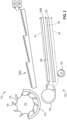
FIG. 3 is a side view of a grain separating system, including a step pan, a grate, and a grain sensor. -
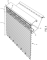
FIG. 4 is a perspective view of the grain separating system ofFIG. 3 . -
FIG. 5 is a cross-sectional side view of the grate and grain sensor ofFIG. 3 . -
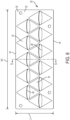
FIG. 6 is a top view of the grate ofFIG. 3 . -
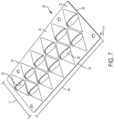
FIG. 7 is a perspective view of the grate ofFIG. 3 . - Before any embodiments of the disclosure are explained in detail, it is to be understood that the disclosure is not limited in its application to the details of construction and the arrangement of components set forth in the following description or illustrated in the accompanying drawings. The disclosure is capable of supporting other embodiments and of being practiced or of being carried out in various ways. Also, it is to be understood that the phraseology and terminology used herein is for the purpose of description and should not be regarded as limiting.
- Grain harvesting
vehicles 100 such as combine harvesters reap crops such as wheat/ oats, rye, barley, corn and the like. Reaping of crops is carried out by various heads orheader assemblies 104 that may be removable and replaceable from thefront 108A of thebody 108 of thevehicle 100 when switching between the harvesting of different crops. A rear 108B of thebody 108 of thevehicle 100 is opposite thefront 108A. Theheader 104 cuts and/or gathers the grain from the field, although the gathered grain is accompanied by material other than grain (MOG) such as straw and chaff. Therefore, the grain harvestingvehicle 100 is provided with a number ofsystems 112 for separating the grain from the MOG so that the grain is collected in a grain tank and the MOG is discarded. The first such system is the threshingcylinder 116. Theheader 104 feeds the grain and MOG to the threshingcylinder 116. The threshingcylinder 116 includesrasp bars 118 that separate the grain and chaff from a majority of the straw, moving the straw to astraw walker 126A, and eventually to the rear 108B of thevehicle 100 where the straw is discarded to the environment by astraw chopper 130 orwindrowing system 152. Grain in thestraw walker 126A passes through openings in thestraw walker 126A and falls to the upper andlower sieves - Additionally, the grain, chaff, and some straw within the threshing
cylinder 116 passes through openings in a concave 114 and to acleaning shoe 132 having a plurality of chaffers or sieves (e.g., the upper sieve orchaffer 120, the lower sieve 122). Thesieves sieves sieves fan 134 over therespective sieve sieve sieve sieves vehicle 100 if grain does not fall through thechaffer 120 and instead is carried to the rear of thechaffer 120. Thechaffer 120 is unable to separate all of the grain from the MOG in thechaffer 120 for example, if thecleaning shoe 132 is overloaded with product, then not all of the product will fall through thechaffer 120. Additionally, if the angles of the louvers of thechaffer 120 are set at an inadequate angle, not all of the grain will fall through. Further still, if the airspeed from thefan 134 is too high, it can move the product past thechaffer 120 too quickly. - It is beneficial to measure the grain loss at the rear of the
chaffer 120 in real time so that the operator can make live adjustments to fan speed, grain feed rate, and/or an angle or speed of thechaffer 120 to limit grain loss. Further, the information can be forwarded to acontroller 48 for various systems on thecombine harvester 100 to automatically adjust such settings. - Unless otherwise specified, with respect to the contents of this application, the term "lost grain" refers to the grain that does not fall through the
chaffer 120 to the collection area (at the auger 124), and is instead carried off of the rear of thechaffer 120 to thestep pan 18 and grate 20 as described below. It is to be understood that this lost grain may be discarded to the environment with the MOG or may otherwise enter a secondary collection in which the grain is eventually separated from the MOG and transferred to a storage tank (and is therefore not "lost" in the traditional sense). - The upper sieve or
chaffer 120 oscillates via a drive apparatus (e.g., a motor, a piston, etc.) to move material along the length of thechaffer 120 from afront end 120A toward arear end 120B. Astep pan 18 is fastened at therear end 120B of the chaffer 120 (e.g., via a threaded fastener 50) such that material that continues off therear end 120B of thechaffer 120 is transferred to thestep pan 18. Thestep pan 18 includesridges 18A spaced apart along the length L2 of thestep pan 18 similar to the ridges of the chaffer. However, unlike, thechaffer 120, thestep pan 18 does not have any apertures extending therethrough for the separation of grain from MOG. Rather, thestep pan 18 directs the MOG and remaining grain to a grate orgrid 20. - As shown in
FIG. 1 , thegrate 20 is positioned at the rear of the step pan 18 (or may be formed integrally with the step pan 18) to direct the grain 14 toward agrain impinging surface 38 of agrain sensor 36. Thegrate 20 is a generallyplanar panel 22 having a length L1, a width W1 perpendicular to the length L1, and a thickness T1 perpendicular to the length L1 and width W1. The width W1 is greater than the length L1 and the length L1 is greater than the thickness T1. The length L1 of the grate is parallel with the flow direction of the grain and MOG from theupstream chaffer 120 and extends from afront side 42 to arear side 44. - The
grate 20 may be attached to the step pan byfasteners 52 and therefore movable with thestep pan 18. Alternatively, thegrate 20 may be separated from thestep pan 18 andchaffer 120 and may be otherwise controlled by a secondary system such that the motion of thegrate 20 can vary relative to the motion of thestep pan 18. - As shown in
FIGS. 5-7 , thegrate 20 may comprise a plurality ofindividual grate panels 22 positioned next to one another that collectively define thegrate 20. Thegrate 20 includesapertures 28 extending through the thickness T1 of thepanel 22 from anupper surface 24 to alower surface 26 to define a passageway through thegrate 20. Each aperture may have a width of, for example, forty to sixty millimeters. - With continued reference to
FIGS. 5-7 , a hollowsemi-conical ramp 34 is positioned between thefront side 42 of thegrate 20 and eachaperture 28. Theramp portion 34 begins at a point on theupper surface 24 of thegrate 20 and increases in width and height in the lengthwise direction (i.e., in the direction of the length L1 of the grate 20) toward therear side 44 of thegrate 20. Theramp portion 34 is hollow, and may have a thickness similar to or less than the thickness T1 of thegrate 20. - A
similar ramp portion 46 is mirrored on the rear side of theaperture 28 on thelower surface 26 of thegrate 20 to form a lowercupped ramp 46. Therefore, the lowercupped ramp 46 is similar in shape and size to theramp portion 34, except as otherwise described. - Therefore, the
aperture 28, when viewed from above (in a plane perpendicular to the thickness T1 of thegrate 20 as shown inFIG. 6 ) appears elliptical. However, the size of the aperture is substantially larger due to the path provided by thehollow ramp portions grate 20. As shown inFIG. 5 , theaperture 28 has a cylindrical shape at least partially defined by theramp portions grate 20 at an angle parallel to the rise of theramp portions 34, 46 (e.g., at a 20 - 30 degree angle relative to the plane of the planar panel 22). As an alternative, the aperture 28 (and/orrelated ramp portions 34, 46) may have a different shape, such as a rectangular shape, a triangular shape, or a circular shape, that may provide a different percent open area for engaging the material and accepting the grain. For example, utilizing a wide rectangular aperture as opposed to the elliptical opening shown may provide a larger open area to engage a greater percentage of the material. - The
grate 20 includes a plurality of theapertures 28 positioned adjacent to one another, as shown inFIG. 6 . Therefore, thepanel 22 defines a circuitous path between theramps apertures 28 in the lengthwise direction to eliminate straight paths in the lengthwise direction along which grain could bypass the apertures. - The increasing shape of the ramp 34 (from the
front side 42 toward the rear side 44) directs the lighter materials (the chaff and straw; the MOG) away from or over theapertures 28, while the heavier grain is collected within the recessed pockets defined by the hollow andcupped ramp portion 46. - A plurality of grain sensors 36 (e.g., a pressure sensor, a force sensor, a vision-based sensor such as a camera system, a contact sensor, a radio frequency sensor, etc.) are positioned below the
grate 20. Eachsensor 36 includes a sensing location at which the grain that falls through theaperture 28 is sensed. For contact-type sensors (such as pressure sensors, force sensors, and some vision-based sensors), the sensing location is at least onegrain impingement surface 38 that measures the impact of a grain. For non-contact sensors (such as some vision-based sensors and radio frequency sensors), the sensing location is the location at which the sensor measures or recognizes the presence of the grain. For example, a camera or radio frequency sensor may be directional to record grain passing by a certain location within the range of the sensor. In this scenario, the sensing location includes the range of the sensor. As a further alternative, eachsensor 36 may include a system of vision-based sensors or radio frequency sensors directed toward one another to measure or record the grains falling therebetween. In this scenario, the sensing location includes the locations measured and recorded between the sensors. In these non-contact scenarios, the direction of grain, as directed by thelower ramps 46 may be orthogonal to the sensing orientation of the sensors. - Each grain sensor is arranged below the
grate 20 in a position such that grains falling through one or more of theapertures 28 in thegrate 20 contact theimpingement surface 38. More specifically, thesensors 36 are angled such that as the grain falls through theapertures 28 along the hollowlower ramp 46, the grain impinges directly into theimpingement surface 38. Written another way, thegrain impingement surface 38 is generally planar. Thesensor 36 is positioned such that the grain impinges perpendicular to the plane of theimpingement surface 38 so the force or pressure measured by thesensor 36 is provided normal to theimpingement surface 38. - The hollow
lower ramp 46 defines a grain path through thegrate 20, as shown by arrow A5. Thelower ramp 46 extends linearly down from thegrate panel 22 at an angle relative to the length L1 of thegrate panel 22, as shown inFIG. 5 , of approximately twenty to thirty degrees from thegrate panel 22 toward thefront side 42 of thegrate 20. However, other angles (e.g., between 10 and 45 degrees, between 15 and 35 degrees, between 20 and 25 degrees) may be utilized. The angle of thelower ramp 46 and the angle of theimpingement surface 38 may be complementary angles, or may be offset from being complimentary angles by a small offset (e.g., 5 degrees, 10 degrees) to account for gravity and component placement. - In order to ensure that the MOG is not being pulled through the
apertures 28 in thegrate 20 toward thesensor 36, the geometry of theapertures 28 in the grate creates a neutral or positive airflow through thegrate apertures 28 from below. For redundancy or a backup, a duct (as indicated by one or both of arrows A2, A3 inFIG. 2 ) from thecleaning shoe 132 may direct airflow directly to the underside of thegrate apertures 28 to ensure a positive airflow therethrough. - In closed tailboard vehicles, a chopper (not shown) is positioned behind and below the rear 44 of the
grate 20. The chopper intakes the MOG from thegrate 20 as well as thestraw walker 126A and chops the MOG and spreads the chopped MOG throughout the field outside thevehicle 100. The grain that impinges off of thegrain sensor 36 likewise is directed to the chopper where it is spread to the field. Alternatively, a recovery system may gather the grain that impinges off of the grain sensor for re-sifting and/or conveyance to a grain storage tank. - A
shield 54 is positioned at the rear 44 of thegrate 20, extending downward from thegrate 20. Theshield 54 prevents kickback of husks or rocks from ricocheting off of the blades of the chopper and damaging thesensor 36. Such ashield 54 is therefore more relevant to combineharvesters 100 having a chopper, such as closed tailboard vehicles. - In operation, grain and MOG is provided to the upper sieve or
chaffer 120 where a majority of the MOG (not previously separated via the threshing cylinder 116) is separated from the grain, and the grain is moved successfully to the collection area (at the auger 124). Thechaffer 120 oscillates to stratify and separate the grain from the MOG, and an airflow A1 (in combination with the shaking motion) moves the MOG and any remaining grain along the length of thechaffer 120 to further openings along thechaffer 120 until the remaining material on thechaffer 120 is mainly comprised of MOG. The airflow A1 and oscillation of thechaffer 120 moves the remaining material off of the rear 120B of thechaffer 120 and onto thestep pan 18. Thestep pan 18 conveys the material along an upper surface with continued oscillating motion to stratify the grain from the MOG, separating the heavier, smaller grain such that it settles within thesteps 18A, while the larger MOG primarily passes over the crests of thesteps 18A. Thestep pan 18 conveys the material to thegrate 20 by shaking or agitating in a diagonal direction (up-right and down-left, according to the orientation ofFig. 3 and as shown by arrow A6) with thechaffer 120 to stratify the grain. - Once at the
grate 20, the grate oscillates in a direction that is generally parallel with the angle of theramps apertures 28, directed away from theapertures 28 by thesemi-conical ramps 34. Once the MOG has traversed past theramps 34, it falls off the back of thegrate 20 and to the chopper, where it is cut and spread to the field. - On the other hand, once the grain reaches the
grate 20, it settles within the lowercupped ramp 46 based on the weight and size of the grain and the continued stratification of the grain caused by the oscillating motion of thegrate 20. The grain then continues along the grain path A5 described above, extending down the lowercupped ramp 46, under theupper ramp 34, until the grain contacts theimpingement surface 38 of thegrain sensor 36. The contact of the grain against thesensor 36 generates an electrical signal that is analyzed by acontroller 48 and/or an operator to provide real-time feedback of the efficiency of thechaffer 120. - Various features of the disclosure are set forth in the following claims.
Claims (6)
- A grain harvesting vehicle (100) configured to harvest a grain, the grain harvesting vehicle (100) comprising:a chaffer (120) configured to separate grain from material other than grain (MOG);a grate (20) positioned rearward of the chaffer (120), the grate (20) comprising:a grate panel (22) having an upper surface and a lower surface;an aperture (28) in the grate panel (22) extending between the upper surface and the lower surface, the aperture (28) having a first end nearer the chaffer (120) and a second end opposite the first end; anda first ramp portion (34) extending above the grate panel (22) from adjacent the first end of the aperture (28) toward the second end of the aperture (28); anda grain sensor (36) having a sensing location positioned at a height below the grate (20),characterized in that the first ramp portion (34) is hollow and begins at a point on the upper surface (24) of the grate (20) and increases in width and height in the direction of the length (L1) of the grate (20) toward the rear side (44) of the grate (20), that the grate (20) further includes a second ramp portion (46) extending below the grate panel (22) from adjacent the second end of the aperture (28) toward the first end of the aperture (28), and that the first ramp portion (34) is mirrored relative to the second ramp portion (46) such that the second ramp portion (46) forms a lower cupped ramp on the lower surface (26) of the grate (20)..
- The grain harvesting vehicle (100) of claim 1, wherein the sensing location is a grain impinging surface and is substantially perpendicular to the ramp portion
- The grain harvesting vehicle (100) of claim 1, wherein the aperture (28) is at least partially defined by the first ramp portion (34) and the second ramp portion (46).
- The grain harvesting vehicle (100) of claim 1, wherein the first ramp portion (34) is a hollow semi-conical ramp.
- The grain harvesting vehicle (100) of claim 1, further comprising a shield (54) positioned at the rear of the grate (20) and extending downward from the grate (20).
- The grain harvesting vehicle (100) of claim 1, further comprising a step pan (18) fastened to the chaffer (120) such that motion of the chaffer (120) is transmittable to the step pan (18), and wherein the grate (20) is fastened to the step pan (18) such that motion of the chaffer (120) is transmittable to the grate (20).
Applications Claiming Priority (1)
| Application Number | Priority Date | Filing Date | Title |
|---|---|---|---|
| US16/046,620 US11013175B2 (en) | 2018-07-26 | 2018-07-26 | Grain loss apparatus for a grain harvesting vehicle |
Publications (2)
| Publication Number | Publication Date |
|---|---|
| EP3598884A1 EP3598884A1 (en) | 2020-01-29 |
| EP3598884B1 true EP3598884B1 (en) | 2023-09-20 |
Family
ID=67262126
Family Applications (1)
| Application Number | Title | Priority Date | Filing Date |
|---|---|---|---|
| EP19185936.2A Active EP3598884B1 (en) | 2018-07-26 | 2019-07-12 | Grain loss apparatus for a grain harvesting vehicle |
Country Status (3)
| Country | Link |
|---|---|
| US (1) | US11013175B2 (en) |
| EP (1) | EP3598884B1 (en) |
| BR (1) | BR102019008291B1 (en) |
Families Citing this family (6)
| Publication number | Priority date | Publication date | Assignee | Title |
|---|---|---|---|---|
| US11083137B2 (en) * | 2018-05-01 | 2021-08-10 | Deere & Company | Return pan grain presentation to a sensor |
| US12207594B2 (en) * | 2020-07-31 | 2025-01-28 | Deere & Company | Partially-unlouvered sieve mechanism |
| CN114846990B (en) * | 2022-03-24 | 2023-06-09 | 江苏大学 | A cleaning loss detection device, harvester and method |
| CA3265164A1 (en) * | 2022-08-15 | 2024-02-22 | Bushel Plus Ltd. | Grain loss detectors for a combine harvester |
| US12310285B2 (en) | 2023-02-27 | 2025-05-27 | Deere & Company | Agricultural operation evaluation system and method |
| US20250107486A1 (en) * | 2023-10-02 | 2025-04-03 | Deere & Company | Overblown grain loss detection |
Citations (1)
| Publication number | Priority date | Publication date | Assignee | Title |
|---|---|---|---|---|
| US4517792A (en) * | 1982-05-07 | 1985-05-21 | Deere & Company | Grain loss monitor sensor mounting arrangement for a combine |
Family Cites Families (25)
| Publication number | Priority date | Publication date | Assignee | Title |
|---|---|---|---|---|
| US2253296A (en) | 1938-11-21 | 1941-08-19 | Hart Carter Co | Screen for threshing machines |
| US2781097A (en) * | 1951-08-07 | 1957-02-12 | Extraction & Chemical Company | Manufacturing small-hole sieves |
| ES364731A1 (en) | 1968-03-15 | 1970-12-16 | Deere & Co | Apparatus for measuring grain losses in threshing machines, particularly harvester-threshers |
| US3638659A (en) * | 1970-04-03 | 1972-02-01 | Case Co J I | Grain loss monitoring device |
| BE761020A (en) | 1970-12-30 | 1971-05-27 | Clayson Nv | SEPARATING DEVICE FOR CEREAL OR THE LIKE FROM CROP OR STRAW FOR DEVICES FOR MEASURING GRAIN LOSSES IN COMBINES, (EXEC.: F. DE COENE AND G. STRUBBE). |
| US4036065A (en) * | 1976-05-11 | 1977-07-19 | Senstek Ltd. | Grain loss monitor |
| US4230130A (en) * | 1979-02-05 | 1980-10-28 | International Harvester Company | Combine grain loss sensing |
| US5176574A (en) * | 1991-06-24 | 1993-01-05 | Case Corporation | Combine cleaning system |
| DE4133976A1 (en) * | 1991-10-14 | 1993-04-15 | Claas Ohg | CORE CURRENT MEASURING DEVICE, ESPECIALLY FOR HARVESTING MACHINES |
| DE4424383C2 (en) * | 1994-07-13 | 2003-05-15 | Schumacher Gmbh Geb | Harvester screen |
| US5466190A (en) | 1994-07-25 | 1995-11-14 | Deere & Company | Precleaner for a cleaning shoe |
| DE19927933B4 (en) * | 1999-06-18 | 2008-07-03 | Gebr. Schumacher Gerätebaugesellschaft mbH | Screen for a threshing machine, in particular for a combine harvester for harvesting grain crops |
| DE10162354A1 (en) | 2001-12-18 | 2003-07-03 | Claas Selbstfahr Erntemasch | Loss determination method on agricultural harvesters |
| US6790137B2 (en) * | 2002-01-25 | 2004-09-14 | Marvin James Gorden | High capacity air jet chaffer |
| US6773343B2 (en) | 2002-07-31 | 2004-08-10 | Deere & Company | Front chaffer and cleaning fan |
| DE10327758A1 (en) * | 2003-06-18 | 2005-01-05 | Claas Selbstfahrende Erntemaschinen Gmbh | Method for controlling a threshing unit of a combine harvester |
| EP1516522B2 (en) * | 2003-09-19 | 2023-03-29 | CLAAS Selbstfahrende Erntemaschinen GmbH | Method and device for determining the amount of tailings return |
| DE102005042049A1 (en) * | 2005-09-02 | 2007-03-29 | Claas Selbstfahrende Erntemaschinen Gmbh | Device and method for the detection of structure-borne sound vibrations |
| DE102005047335A1 (en) * | 2005-09-30 | 2007-04-12 | Claas Selbstfahrende Erntemaschinen Gmbh | Self-propelled harvester and operating method for it |
| US9631964B2 (en) * | 2011-03-11 | 2017-04-25 | Intelligent Agricultural Solutions, Llc | Acoustic material flow sensor |
| US9474208B2 (en) * | 2011-11-15 | 2016-10-25 | Appareo Systems, Llc | System and method for determining material yield and/or loss from a harvesting machine using acoustic sensors |
| DE102011052280A1 (en) | 2011-07-29 | 2013-01-31 | Claas Selbstfahrende Erntemaschinen Gmbh | Avoidance of cleaning losses with strong lateral inclination |
| US9699970B2 (en) | 2013-09-19 | 2017-07-11 | Cnh Industrial America Llc | Combine side-shake cleaning control system |
| BE1022414B1 (en) * | 2014-10-14 | 2016-03-24 | Cnh Industrial Belgium Nv | SENSOR SET-UP FOR MOWING DISHER FOR DETECTING CLEAN GRAIN LOSS |
| US10334781B2 (en) * | 2015-08-20 | 2019-07-02 | Cnh Industrial America Llc | Side shake rate based on machine throughputs |
-
2018
- 2018-07-26 US US16/046,620 patent/US11013175B2/en active Active
-
2019
- 2019-04-24 BR BR102019008291-7A patent/BR102019008291B1/en active IP Right Grant
- 2019-07-12 EP EP19185936.2A patent/EP3598884B1/en active Active
Patent Citations (1)
| Publication number | Priority date | Publication date | Assignee | Title |
|---|---|---|---|---|
| US4517792A (en) * | 1982-05-07 | 1985-05-21 | Deere & Company | Grain loss monitor sensor mounting arrangement for a combine |
Also Published As
| Publication number | Publication date |
|---|---|
| US20200029498A1 (en) | 2020-01-30 |
| US11013175B2 (en) | 2021-05-25 |
| BR102019008291A2 (en) | 2020-02-04 |
| EP3598884A1 (en) | 2020-01-29 |
| BR102019008291B1 (en) | 2024-01-16 |
Similar Documents
| Publication | Publication Date | Title |
|---|---|---|
| US11013175B2 (en) | Grain loss apparatus for a grain harvesting vehicle | |
| US9167749B2 (en) | Cleaning apparatus effectiveness measuring system for a combine harvester | |
| US6773343B2 (en) | Front chaffer and cleaning fan | |
| US10721869B2 (en) | Agricultural harvester with laterally moving grain pan | |
| EP3687276B1 (en) | Automatic chopper pan control | |
| EP3449717B1 (en) | Straw deflector for an agricultural combine | |
| EP2912936B2 (en) | Control of airflow characteristics in an agricultural harvester | |
| US10039236B2 (en) | Grain cleaning system having improved air flow and additional fall step to improve grain cleaning performance | |
| US20250287871A1 (en) | Grain loss detectors for a combine harvester | |
| EP3563660B1 (en) | Return pan grain presentation to a sensor | |
| EP3135097B1 (en) | Grain pan and sieve dividers | |
| US9883631B2 (en) | Crop processing apparatus in a combine harvester | |
| JP7399036B2 (en) | combine | |
| US12262661B1 (en) | Sieve chutes for a lower sieve of an agricultural combine | |
| CN107846844B (en) | Auger assembly for agricultural harvester | |
| EP4091431B1 (en) | Sieve for an agricultural harvester including extruded sides with strips | |
| US12550819B2 (en) | Residue sensor protection on a harvester | |
| JP7399038B2 (en) | combine |
Legal Events
| Date | Code | Title | Description |
|---|---|---|---|
| STAA | Information on the status of an ep patent application or granted ep patent |
Free format text: STATUS: UNKNOWN |
|
| PUAI | Public reference made under article 153(3) epc to a published international application that has entered the european phase |
Free format text: ORIGINAL CODE: 0009012 |
|
| STAA | Information on the status of an ep patent application or granted ep patent |
Free format text: STATUS: THE APPLICATION HAS BEEN PUBLISHED |
|
| AK | Designated contracting states |
Kind code of ref document: A1 Designated state(s): AL AT BE BG CH CY CZ DE DK EE ES FI FR GB GR HR HU IE IS IT LI LT LU LV MC MK MT NL NO PL PT RO RS SE SI SK SM TR |
|
| AX | Request for extension of the european patent |
Extension state: BA ME |
|
| STAA | Information on the status of an ep patent application or granted ep patent |
Free format text: STATUS: REQUEST FOR EXAMINATION WAS MADE |
|
| 17P | Request for examination filed |
Effective date: 20200729 |
|
| RBV | Designated contracting states (corrected) |
Designated state(s): AL AT BE BG CH CY CZ DE DK EE ES FI FR GB GR HR HU IE IS IT LI LT LU LV MC MK MT NL NO PL PT RO RS SE SI SK SM TR |
|
| STAA | Information on the status of an ep patent application or granted ep patent |
Free format text: STATUS: EXAMINATION IS IN PROGRESS |
|
| 17Q | First examination report despatched |
Effective date: 20220215 |
|
| GRAP | Despatch of communication of intention to grant a patent |
Free format text: ORIGINAL CODE: EPIDOSNIGR1 |
|
| STAA | Information on the status of an ep patent application or granted ep patent |
Free format text: STATUS: GRANT OF PATENT IS INTENDED |
|
| INTG | Intention to grant announced |
Effective date: 20230510 |
|
| GRAS | Grant fee paid |
Free format text: ORIGINAL CODE: EPIDOSNIGR3 |
|
| GRAA | (expected) grant |
Free format text: ORIGINAL CODE: 0009210 |
|
| STAA | Information on the status of an ep patent application or granted ep patent |
Free format text: STATUS: THE PATENT HAS BEEN GRANTED |
|
| AK | Designated contracting states |
Kind code of ref document: B1 Designated state(s): AL AT BE BG CH CY CZ DE DK EE ES FI FR GB GR HR HU IE IS IT LI LT LU LV MC MK MT NL NO PL PT RO RS SE SI SK SM TR |
|
| REG | Reference to a national code |
Ref country code: GB Ref legal event code: FG4D |
|
| REG | Reference to a national code |
Ref country code: CH Ref legal event code: EP |
|
| REG | Reference to a national code |
Ref country code: DE Ref legal event code: R096 Ref document number: 602019037717 Country of ref document: DE |
|
| REG | Reference to a national code |
Ref country code: IE Ref legal event code: FG4D |
|
| REG | Reference to a national code |
Ref country code: LT Ref legal event code: MG9D |
|
| PG25 | Lapsed in a contracting state [announced via postgrant information from national office to epo] |
Ref country code: GR Free format text: LAPSE BECAUSE OF FAILURE TO SUBMIT A TRANSLATION OF THE DESCRIPTION OR TO PAY THE FEE WITHIN THE PRESCRIBED TIME-LIMIT Effective date: 20231221 |
|
| REG | Reference to a national code |
Ref country code: NL Ref legal event code: MP Effective date: 20230920 |
|
| PG25 | Lapsed in a contracting state [announced via postgrant information from national office to epo] |
Ref country code: SE Free format text: LAPSE BECAUSE OF FAILURE TO SUBMIT A TRANSLATION OF THE DESCRIPTION OR TO PAY THE FEE WITHIN THE PRESCRIBED TIME-LIMIT Effective date: 20230920 Ref country code: RS Free format text: LAPSE BECAUSE OF FAILURE TO SUBMIT A TRANSLATION OF THE DESCRIPTION OR TO PAY THE FEE WITHIN THE PRESCRIBED TIME-LIMIT Effective date: 20230920 Ref country code: NO Free format text: LAPSE BECAUSE OF FAILURE TO SUBMIT A TRANSLATION OF THE DESCRIPTION OR TO PAY THE FEE WITHIN THE PRESCRIBED TIME-LIMIT Effective date: 20231220 Ref country code: LV Free format text: LAPSE BECAUSE OF FAILURE TO SUBMIT A TRANSLATION OF THE DESCRIPTION OR TO PAY THE FEE WITHIN THE PRESCRIBED TIME-LIMIT Effective date: 20230920 Ref country code: LT Free format text: LAPSE BECAUSE OF FAILURE TO SUBMIT A TRANSLATION OF THE DESCRIPTION OR TO PAY THE FEE WITHIN THE PRESCRIBED TIME-LIMIT Effective date: 20230920 Ref country code: HR Free format text: LAPSE BECAUSE OF FAILURE TO SUBMIT A TRANSLATION OF THE DESCRIPTION OR TO PAY THE FEE WITHIN THE PRESCRIBED TIME-LIMIT Effective date: 20230920 Ref country code: GR Free format text: LAPSE BECAUSE OF FAILURE TO SUBMIT A TRANSLATION OF THE DESCRIPTION OR TO PAY THE FEE WITHIN THE PRESCRIBED TIME-LIMIT Effective date: 20231221 Ref country code: FI Free format text: LAPSE BECAUSE OF FAILURE TO SUBMIT A TRANSLATION OF THE DESCRIPTION OR TO PAY THE FEE WITHIN THE PRESCRIBED TIME-LIMIT Effective date: 20230920 |
|
| REG | Reference to a national code |
Ref country code: AT Ref legal event code: MK05 Ref document number: 1612647 Country of ref document: AT Kind code of ref document: T Effective date: 20230920 |
|
| PG25 | Lapsed in a contracting state [announced via postgrant information from national office to epo] |
Ref country code: NL Free format text: LAPSE BECAUSE OF FAILURE TO SUBMIT A TRANSLATION OF THE DESCRIPTION OR TO PAY THE FEE WITHIN THE PRESCRIBED TIME-LIMIT Effective date: 20230920 |
|
| PG25 | Lapsed in a contracting state [announced via postgrant information from national office to epo] |
Ref country code: IS Free format text: LAPSE BECAUSE OF FAILURE TO SUBMIT A TRANSLATION OF THE DESCRIPTION OR TO PAY THE FEE WITHIN THE PRESCRIBED TIME-LIMIT Effective date: 20240120 |
|
| PG25 | Lapsed in a contracting state [announced via postgrant information from national office to epo] |
Ref country code: AT Free format text: LAPSE BECAUSE OF FAILURE TO SUBMIT A TRANSLATION OF THE DESCRIPTION OR TO PAY THE FEE WITHIN THE PRESCRIBED TIME-LIMIT Effective date: 20230920 |
|
| PG25 | Lapsed in a contracting state [announced via postgrant information from national office to epo] |
Ref country code: ES Free format text: LAPSE BECAUSE OF FAILURE TO SUBMIT A TRANSLATION OF THE DESCRIPTION OR TO PAY THE FEE WITHIN THE PRESCRIBED TIME-LIMIT Effective date: 20230920 |
|
| PG25 | Lapsed in a contracting state [announced via postgrant information from national office to epo] |
Ref country code: SM Free format text: LAPSE BECAUSE OF FAILURE TO SUBMIT A TRANSLATION OF THE DESCRIPTION OR TO PAY THE FEE WITHIN THE PRESCRIBED TIME-LIMIT Effective date: 20230920 Ref country code: RO Free format text: LAPSE BECAUSE OF FAILURE TO SUBMIT A TRANSLATION OF THE DESCRIPTION OR TO PAY THE FEE WITHIN THE PRESCRIBED TIME-LIMIT Effective date: 20230920 Ref country code: IS Free format text: LAPSE BECAUSE OF FAILURE TO SUBMIT A TRANSLATION OF THE DESCRIPTION OR TO PAY THE FEE WITHIN THE PRESCRIBED TIME-LIMIT Effective date: 20240120 Ref country code: ES Free format text: LAPSE BECAUSE OF FAILURE TO SUBMIT A TRANSLATION OF THE DESCRIPTION OR TO PAY THE FEE WITHIN THE PRESCRIBED TIME-LIMIT Effective date: 20230920 Ref country code: EE Free format text: LAPSE BECAUSE OF FAILURE TO SUBMIT A TRANSLATION OF THE DESCRIPTION OR TO PAY THE FEE WITHIN THE PRESCRIBED TIME-LIMIT Effective date: 20230920 Ref country code: CZ Free format text: LAPSE BECAUSE OF FAILURE TO SUBMIT A TRANSLATION OF THE DESCRIPTION OR TO PAY THE FEE WITHIN THE PRESCRIBED TIME-LIMIT Effective date: 20230920 Ref country code: AT Free format text: LAPSE BECAUSE OF FAILURE TO SUBMIT A TRANSLATION OF THE DESCRIPTION OR TO PAY THE FEE WITHIN THE PRESCRIBED TIME-LIMIT Effective date: 20230920 Ref country code: SK Free format text: LAPSE BECAUSE OF FAILURE TO SUBMIT A TRANSLATION OF THE DESCRIPTION OR TO PAY THE FEE WITHIN THE PRESCRIBED TIME-LIMIT Effective date: 20230920 Ref country code: PT Free format text: LAPSE BECAUSE OF FAILURE TO SUBMIT A TRANSLATION OF THE DESCRIPTION OR TO PAY THE FEE WITHIN THE PRESCRIBED TIME-LIMIT Effective date: 20240122 |
|
| PG25 | Lapsed in a contracting state [announced via postgrant information from national office to epo] |
Ref country code: PL Free format text: LAPSE BECAUSE OF FAILURE TO SUBMIT A TRANSLATION OF THE DESCRIPTION OR TO PAY THE FEE WITHIN THE PRESCRIBED TIME-LIMIT Effective date: 20230920 Ref country code: IT Free format text: LAPSE BECAUSE OF FAILURE TO SUBMIT A TRANSLATION OF THE DESCRIPTION OR TO PAY THE FEE WITHIN THE PRESCRIBED TIME-LIMIT Effective date: 20230920 |
|
| REG | Reference to a national code |
Ref country code: DE Ref legal event code: R097 Ref document number: 602019037717 Country of ref document: DE |
|
| PG25 | Lapsed in a contracting state [announced via postgrant information from national office to epo] |
Ref country code: DK Free format text: LAPSE BECAUSE OF FAILURE TO SUBMIT A TRANSLATION OF THE DESCRIPTION OR TO PAY THE FEE WITHIN THE PRESCRIBED TIME-LIMIT Effective date: 20230920 |
|
| PLBE | No opposition filed within time limit |
Free format text: ORIGINAL CODE: 0009261 |
|
| STAA | Information on the status of an ep patent application or granted ep patent |
Free format text: STATUS: NO OPPOSITION FILED WITHIN TIME LIMIT |
|
| PG25 | Lapsed in a contracting state [announced via postgrant information from national office to epo] |
Ref country code: DK Free format text: LAPSE BECAUSE OF FAILURE TO SUBMIT A TRANSLATION OF THE DESCRIPTION OR TO PAY THE FEE WITHIN THE PRESCRIBED TIME-LIMIT Effective date: 20230920 |
|
| 26N | No opposition filed |
Effective date: 20240621 |
|
| PG25 | Lapsed in a contracting state [announced via postgrant information from national office to epo] |
Ref country code: SI Free format text: LAPSE BECAUSE OF FAILURE TO SUBMIT A TRANSLATION OF THE DESCRIPTION OR TO PAY THE FEE WITHIN THE PRESCRIBED TIME-LIMIT Effective date: 20230920 |
|
| PG25 | Lapsed in a contracting state [announced via postgrant information from national office to epo] |
Ref country code: SI Free format text: LAPSE BECAUSE OF FAILURE TO SUBMIT A TRANSLATION OF THE DESCRIPTION OR TO PAY THE FEE WITHIN THE PRESCRIBED TIME-LIMIT Effective date: 20230920 |
|
| PG25 | Lapsed in a contracting state [announced via postgrant information from national office to epo] |
Ref country code: BG Free format text: LAPSE BECAUSE OF FAILURE TO SUBMIT A TRANSLATION OF THE DESCRIPTION OR TO PAY THE FEE WITHIN THE PRESCRIBED TIME-LIMIT Effective date: 20230920 |
|
| PG25 | Lapsed in a contracting state [announced via postgrant information from national office to epo] |
Ref country code: BG Free format text: LAPSE BECAUSE OF FAILURE TO SUBMIT A TRANSLATION OF THE DESCRIPTION OR TO PAY THE FEE WITHIN THE PRESCRIBED TIME-LIMIT Effective date: 20230920 |
|
| PG25 | Lapsed in a contracting state [announced via postgrant information from national office to epo] |
Ref country code: MC Free format text: LAPSE BECAUSE OF FAILURE TO SUBMIT A TRANSLATION OF THE DESCRIPTION OR TO PAY THE FEE WITHIN THE PRESCRIBED TIME-LIMIT Effective date: 20230920 |
|
| REG | Reference to a national code |
Ref country code: CH Ref legal event code: PL |
|
| PG25 | Lapsed in a contracting state [announced via postgrant information from national office to epo] |
Ref country code: LU Free format text: LAPSE BECAUSE OF NON-PAYMENT OF DUE FEES Effective date: 20240712 |
|
| GBPC | Gb: european patent ceased through non-payment of renewal fee |
Effective date: 20240712 |
|
| PG25 | Lapsed in a contracting state [announced via postgrant information from national office to epo] |
Ref country code: LU Free format text: LAPSE BECAUSE OF NON-PAYMENT OF DUE FEES Effective date: 20240712 |
|
| PG25 | Lapsed in a contracting state [announced via postgrant information from national office to epo] |
Ref country code: CH Free format text: LAPSE BECAUSE OF NON-PAYMENT OF DUE FEES Effective date: 20240731 Ref country code: BE Free format text: LAPSE BECAUSE OF NON-PAYMENT OF DUE FEES Effective date: 20240731 |
|
| PG25 | Lapsed in a contracting state [announced via postgrant information from national office to epo] |
Ref country code: FR Free format text: LAPSE BECAUSE OF NON-PAYMENT OF DUE FEES Effective date: 20240731 |
|
| PG25 | Lapsed in a contracting state [announced via postgrant information from national office to epo] |
Ref country code: GB Free format text: LAPSE BECAUSE OF NON-PAYMENT OF DUE FEES Effective date: 20240712 |
|
| REG | Reference to a national code |
Ref country code: BE Ref legal event code: MM Effective date: 20240731 |
|
| PG25 | Lapsed in a contracting state [announced via postgrant information from national office to epo] |
Ref country code: IE Free format text: LAPSE BECAUSE OF NON-PAYMENT OF DUE FEES Effective date: 20240712 |
|
| PGFP | Annual fee paid to national office [announced via postgrant information from national office to epo] |
Ref country code: DE Payment date: 20250620 Year of fee payment: 7 |
|
| PG25 | Lapsed in a contracting state [announced via postgrant information from national office to epo] |
Ref country code: CY Free format text: LAPSE BECAUSE OF FAILURE TO SUBMIT A TRANSLATION OF THE DESCRIPTION OR TO PAY THE FEE WITHIN THE PRESCRIBED TIME-LIMIT; INVALID AB INITIO Effective date: 20190712 |
|
| PG25 | Lapsed in a contracting state [announced via postgrant information from national office to epo] |
Ref country code: HU Free format text: LAPSE BECAUSE OF FAILURE TO SUBMIT A TRANSLATION OF THE DESCRIPTION OR TO PAY THE FEE WITHIN THE PRESCRIBED TIME-LIMIT; INVALID AB INITIO Effective date: 20190712 |
|
| PG25 | Lapsed in a contracting state [announced via postgrant information from national office to epo] |
Ref country code: TR Free format text: LAPSE BECAUSE OF FAILURE TO SUBMIT A TRANSLATION OF THE DESCRIPTION OR TO PAY THE FEE WITHIN THE PRESCRIBED TIME-LIMIT Effective date: 20230920 |