EP3598780A1 - Sound outputting device, processing device and sound controlling method thereof - Google Patents
Sound outputting device, processing device and sound controlling method thereof Download PDFInfo
- Publication number
- EP3598780A1 EP3598780A1 EP19185571.7A EP19185571A EP3598780A1 EP 3598780 A1 EP3598780 A1 EP 3598780A1 EP 19185571 A EP19185571 A EP 19185571A EP 3598780 A1 EP3598780 A1 EP 3598780A1
- Authority
- EP
- European Patent Office
- Prior art keywords
- virtual
- sound signal
- sound
- updated
- original
- Prior art date
- Legal status (The legal status is an assumption and is not a legal conclusion. Google has not performed a legal analysis and makes no representation as to the accuracy of the status listed.)
- Ceased
Links
- 238000000034 method Methods 0.000 title claims abstract description 20
- 238000012545 processing Methods 0.000 title claims abstract description 19
- 230000005236 sound signal Effects 0.000 claims abstract description 166
- 230000001131 transforming effect Effects 0.000 claims description 33
- 238000010586 diagram Methods 0.000 description 8
- 238000005516 engineering process Methods 0.000 description 3
- 230000008859 change Effects 0.000 description 2
- 230000002452 interceptive effect Effects 0.000 description 2
- 238000012986 modification Methods 0.000 description 2
- 230000004048 modification Effects 0.000 description 2
- 238000004891 communication Methods 0.000 description 1
- 238000011161 development Methods 0.000 description 1
- 230000009467 reduction Effects 0.000 description 1
- 238000012546 transfer Methods 0.000 description 1
- 230000009466 transformation Effects 0.000 description 1
Images



Classifications
-
- H—ELECTRICITY
- H04—ELECTRIC COMMUNICATION TECHNIQUE
- H04S—STEREOPHONIC SYSTEMS
- H04S7/00—Indicating arrangements; Control arrangements, e.g. balance control
- H04S7/30—Control circuits for electronic adaptation of the sound field
- H04S7/302—Electronic adaptation of stereophonic sound system to listener position or orientation
- H04S7/303—Tracking of listener position or orientation
- H04S7/304—For headphones
-
- H—ELECTRICITY
- H04—ELECTRIC COMMUNICATION TECHNIQUE
- H04S—STEREOPHONIC SYSTEMS
- H04S7/00—Indicating arrangements; Control arrangements, e.g. balance control
- H04S7/30—Control circuits for electronic adaptation of the sound field
- H04S7/302—Electronic adaptation of stereophonic sound system to listener position or orientation
- H04S7/303—Tracking of listener position or orientation
-
- H—ELECTRICITY
- H04—ELECTRIC COMMUNICATION TECHNIQUE
- H04S—STEREOPHONIC SYSTEMS
- H04S1/00—Two-channel systems
- H04S1/007—Two-channel systems in which the audio signals are in digital form
-
- H—ELECTRICITY
- H04—ELECTRIC COMMUNICATION TECHNIQUE
- H04S—STEREOPHONIC SYSTEMS
- H04S2400/00—Details of stereophonic systems covered by H04S but not provided for in its groups
- H04S2400/11—Positioning of individual sound objects, e.g. moving airplane, within a sound field
-
- H—ELECTRICITY
- H04—ELECTRIC COMMUNICATION TECHNIQUE
- H04S—STEREOPHONIC SYSTEMS
- H04S2420/00—Techniques used stereophonic systems covered by H04S but not provided for in its groups
- H04S2420/01—Enhancing the perception of the sound image or of the spatial distribution using head related transfer functions [HRTF's] or equivalents thereof, e.g. interaural time difference [ITD] or interaural level difference [ILD]
Definitions
- the invention relates to a sound outputting device, a processing device and a sound controlling method thereof, and more particular to a two-channel sound outputting device, a processing device and a sound controlling method thereof.
- the user may wear a head-mounted display (HMD) to display a picture of virtual reality (VR) in front of their eyes.
- HMD head-mounted display
- VR virtual reality
- the head-mounted display can present a corresponding picture, allowing the user to feel like being in a certain virtual scene.
- the invention relates to a sound outputting device, a processing device and a sound controlling method thereof.
- the sound signal is transformed according to the rotation of the user to improve the user's presence.
- a sound controlling method includes the following steps. An original left sound signal and an original right sound signal are received. The original left sound signal and the original right sound signal are transformed to be a virtual left sound signal and a virtual right sound signal of a virtual sound source. A rotation degree of a user is detected. The virtual left sound signal and the virtual right sound signal are transformed to be an updated left sound signal and an updated right sound signal.
- the sound outputting device includes a receiving unit, a first transforming unit, a detecting unit, a second transforming unit, a left sound outputting unit, and a right sound outputting unit.
- the receiving unit is used to receive an original left sound signal and an original right sound signal.
- the first transforming unit is used to transform the original left sound signal and the original right sound signal into a virtual left sound signal and a virtual right sound signal of a virtual sound source.
- the detecting unit is used to detect a rotation degree of the user.
- the second transforming unit is used to transform the virtual left sound signal and the virtual right sound signal into an updated left sound signal and an updated right sound signal according to the rotation degree.
- the left sound outputting unit is used to output the updated left sound signal.
- the right sound outputting unit is used to output the updated right sound signal.
- a processing device is proposed.
- the processing device is connected to a sound outputting device.
- the processing device includes a receiving unit, a first transforming unit, a detecting unit, and a second transforming unit.
- the receiving unit is used to receive an original left sound signal and an original right sound signal.
- the first transforming unit is used to transform the original left sound signal and the original right sound signal into a virtual left sound signal and a virtual right sound signal of a virtual sound source.
- the detecting unit is used to detect a rotation degree of the user.
- the second transforming unit is used to transform the virtual left sound signal and the virtual right sound signal into an updated left sound signal and an updated right sound signal according to the rotation degree.
- the updated left sound signal and the updated right sound signal are transmitted to the sound outputting device.
- FIG. 1 it shows a schematic diagram of a sound outputting device 100, a head-mounted display 200, and a processing device 300 according to an embodiment.
- the sound outputting device 100 connected to the head-mounted display 200, can be used with the head-mounted display 200 to allow the user to play a virtual reality (VR) game, or to visit a virtual store.
- the displaying content V2 of the head-mounted display 200 and an original left sound signal eL and an original right sound signal eR of the sound outputting device 100 are provided by the processing device 300.
- the processing device 300 As the user rotates, the displaying content V2 will change accordingly.
- the original left sound signal eL and the original right sound signal eR can be transformed into an updated left sound signal ZL and an updated right sound signal ZR to improve the user's presence.
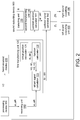
- the sound outputting device 100 comprises a receiving unit 110, a first transforming unit 120, a detecting unit 130, a second transforming unit 140, a left sound outputting unit 150, and a right sound outputting unit 160.
- the receiving unit 110 e.g., a wireless communication module, or a wired network module, is used for receiving signal.
- Each of the first transforming unit 120 and the second transforming unit 140 for example, is a circuit, a chip, a circuit board, or a storage device that stores several groups of codes.
- the detecting unit 130 e.g., a gyro, an accelerometer, an infrared (IR) detector, is used to detect the user's rotation.
- the left sound outputting unit 150 and the right sound outputting unit 160 is an earphone. The operation of those elements is described in more detail as follows, according to the flow chart.
- step S110 the receiving unit 110 receives an original left sound signal eL and an original right sound signal eR.
- the original left sound signal eL and the original right sound signal eR are transmitted directly to the left sound outputting unit 150 and the right sound outputting unit 160 for outputting, respectively.
- the user's presence can be improved.
- step S120 the first transforming unit 120 transforms the original left sound signal eL and the original right sound signal eR into a virtual left sound signal SL and a virtual right sound signal SR of a virtual sound source S.
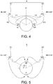
- FIG. 4 it shows a schematic diagram of the virtual sound source S. If the virtual left sound signal SL and the virtual right sound signal SR sent out from the virtual sound source S are known, the original left sound signal eL and the original right sound signal eR can be calculated through the calculation of the Head Related Transfer Functions (HRTF) technology.
- HRTF Head Related Transfer Functions
- the virtual left sound signal SL and the virtual right sound signal SR are calculated according to the original left sound signal eL and the original right sound signal eR.
- step S120 comprises steps S121 to S123.
- a virtual position calculator 121 of the first transforming unit 120 obtains a virtual sound source position of a virtual sound source S relative to the user.
- the virtual sound source S comprises a first virtual speaker S1 and a second virtual speaker S2.
- the virtual sound source position comprises a first relative degree ⁇ L of the first virtual speaker S1 relative to the user, and a second relative degree ⁇ R of the second virtual speaker S2 relative to the user.
- a function calculator 122 of the first transforming unit 120 obtains the characteristic functions H0, H1, H2, H3 of the virtual sound source S corresponding to a left ear and a right ear according to the virtual sound source position (i.e., the first relative degree ⁇ L and the second relative degree ⁇ R).
- a virtual signal calculator 123 of the first transforming unit 120 obtains a virtual left sound signal SL and a virtual right sound signal SR according to the original left sound signal eL, the original right sound signal eR, and the characteristic functions H0, H1, H2, H3.
- the virtual signal calculator 123 calculates the virtual left sound signal SL and the virtual right sound signal SR according to the following equation (1).
- SL SR 1 H 0 ⁇ H 3 ⁇ H 1 ⁇ H 2 H 3 ⁇ H 1 ⁇ H 2 H 0 eL eR
- the detecting unit 130 detects a rotation degree ⁇ of the user.
- the rotation degree ⁇ detected by the detecting unit 130 comprises a direction value, for example, rotating in a counterclockwise direction is a positive direction.
- FIG. 5 it illustrates a situation of a user's rotation.
- the user rotates 90 degree, so the detecting unit 130 may detect that the rotation degree ⁇ is +90 degree.
- step S140 the second transforming unit 140 transforms the virtual left sound signal SL and the virtual right sound signal SR into the updated left sound signal ZL and the updated right sound signal ZR according to the rotation degree ⁇ .
- the updated left sound signal ZL and the updated right sound signal ZR are calculated according to the virtual left sound signal SL and the virtual right sound signal SR which are calculated according to the user's rotation.
- step S140 comprises steps S141 to S142.
- an updated position calculator 141 of the second transforming unit 140 obtains an updated virtual sound source position of the virtual sound source S relative to the user according to the rotation degree ⁇ .
- the updated virtual sound source position includes a first updated relative degree ⁇ L' relative to the user and a second updated relative degree ⁇ R' relative to the user.
- the updated position calculator 141 obtains the first updated relative degree ⁇ L' and the second updated relative degree ⁇ R' according to the following equations (2) and (3).
- step S142 the updated signal calculator 142 of the second transforming unit 140 obtains an updated left sound signal ZL and an updated right sound signal ZR according to the virtual left sound signal SL, the virtual right sound signal SR, and the updated virtual sound source position (i.e., the first updated relative degree ⁇ L' and the second updated relative degree ⁇ R').
- step S150 the left sound outputting unit 150 outputs the updated left sound signal ZL.
- step S160 the right sound outputting unit 160 outputs the updated right sound signal ZR.
- the original left sound signal eL and the original right sound signal can be transformed into the updated left sound signal ZL and the updated right sound signal ZR according to the user's rotation to improve the user's presence.
- this embodiment is not only related to how to perform a signal transformation, but also allows the general sound signal to be intercepted and transformed into a sound signal corresponding to the user's rotation through the implementation of the steps and elements stated above.
- one of the problems to be solved in this embodiment is how to transform a sound signal corresponding to the user's rotation in the case that the virtual sound source is unknown.
- this embodiment proposes a specific inverse calculation technology to obtain the virtual sound source, and is further capable of transforming the sound signal corresponding to the user.
- FIG. 6 it shows a schematic diagram of a sound outputting device 100', a head-mounted display 200', and a processing device300' according to another embodiment.
- the receiving unit 110, the first transforming unit 120, and the second transforming unit 140 stated above may be arranged in the processing device 300'.
- the original left sound signal eL and the original right sound signal eR are transformed into the updated left sound signal ZL and the updated right sound signal ZR through the calculation of the processing device 300', after that, the updated left sound signal ZL and the updated right sound signal ZR are outputted to the sound outputting device 100'.
- the rotation degree ⁇ can be transmitted to the processing device 300' by the sound outputting device 100' to perform calculation.
- the detecting unit 130 stated above is arranged at the processing device 300' (e.g., using an infrared sensor)
- the rotation degree ⁇ does not have to be transmitted to the sound outputting device 100', and the calculation may be performed at the processing device 300' directly.
Landscapes
- Engineering & Computer Science (AREA)
- Physics & Mathematics (AREA)
- Acoustics & Sound (AREA)
- Signal Processing (AREA)
- Multimedia (AREA)
- Stereophonic System (AREA)
Abstract
Description
- The invention relates to a sound outputting device, a processing device and a sound controlling method thereof, and more particular to a two-channel sound outputting device, a processing device and a sound controlling method thereof.
- Along with the development of the interactive display technology, various interactive display devices have been continuously introduced. For example, the user may wear a head-mounted display (HMD) to display a picture of virtual reality (VR) in front of their eyes. As the user moves or rotates, the head-mounted display can present a corresponding picture, allowing the user to feel like being in a certain virtual scene.
- However, in the current application, although the picture can change as the user rotates, the sound signal still remains the same. This causes a great reduction of the user's presence.
- The invention relates to a sound outputting device, a processing device and a sound controlling method thereof. The sound signal is transformed according to the rotation of the user to improve the user's presence.
- According to the first aspect of this invention, a sound controlling method is proposed. The sound controlling method includes the following steps. An original left sound signal and an original right sound signal are received. The original left sound signal and the original right sound signal are transformed to be a virtual left sound signal and a virtual right sound signal of a virtual sound source. A rotation degree of a user is detected. The virtual left sound signal and the virtual right sound signal are transformed to be an updated left sound signal and an updated right sound signal.
- According to the second aspect of this invention, a sound outputting device is proposed. The sound outputting device includes a receiving unit, a first transforming unit, a detecting unit, a second transforming unit, a left sound outputting unit, and a right sound outputting unit. The receiving unit is used to receive an original left sound signal and an original right sound signal. The first transforming unit is used to transform the original left sound signal and the original right sound signal into a virtual left sound signal and a virtual right sound signal of a virtual sound source. The detecting unit is used to detect a rotation degree of the user. The second transforming unit is used to transform the virtual left sound signal and the virtual right sound signal into an updated left sound signal and an updated right sound signal according to the rotation degree. The left sound outputting unit is used to output the updated left sound signal. The right sound outputting unit is used to output the updated right sound signal.
- According to the third aspect of this invention, a processing device is proposed. The processing device is connected to a sound outputting device. The processing device includes a receiving unit, a first transforming unit, a detecting unit, and a second transforming unit. The receiving unit is used to receive an original left sound signal and an original right sound signal. The first transforming unit is used to transform the original left sound signal and the original right sound signal into a virtual left sound signal and a virtual right sound signal of a virtual sound source. The detecting unit is used to detect a rotation degree of the user. The second transforming unit is used to transform the virtual left sound signal and the virtual right sound signal into an updated left sound signal and an updated right sound signal according to the rotation degree. The updated left sound signal and the updated right sound signal are transmitted to the sound outputting device.
- The above and other aspects of the invention will become better understood with regard to the following detailed description of the preferred but non-limiting embodiment(s). The following description is made with reference to the accompanying drawings.
-
-
FIG. 1 shows a schematic diagram of a sound outputting device, a head-mounted display, and a processing device according to an embodiment. -
FIG. 2 shows a block diagram of a sound outputting device. -
FIG. 3 shows a flow chart of a sound controlling method according to an embodiment. -
FIG. 4 shows a schematic diagram of a virtual sound source. -
FIG. 5 shows a situation of a user's rotation. -
FIG. 6 shows a schematic diagram of a sound outputting device, a head-mounted display, and a processing device according to another embodiment. - Referring to
FIG. 1 , it shows a schematic diagram of asound outputting device 100, a head-mounteddisplay 200, and aprocessing device 300 according to an embodiment. Thesound outputting device 100, connected to the head-mounteddisplay 200, can be used with the head-mounteddisplay 200 to allow the user to play a virtual reality (VR) game, or to visit a virtual store. The displaying content V2 of the head-mounteddisplay 200 and an original left sound signal eL and an original right sound signal eR of thesound outputting device 100 are provided by theprocessing device 300. As the user rotates, the displaying content V2 will change accordingly. In this embodiment, according to the rotation of the user, the original left sound signal eL and the original right sound signal eR can be transformed into an updated left sound signal ZL and an updated right sound signal ZR to improve the user's presence. - Referring to
FIG. 2 , it shows a block diagram of asound outputting device 100. Thesound outputting device 100 comprises areceiving unit 110, afirst transforming unit 120, a detectingunit 130, a second transformingunit 140, a leftsound outputting unit 150, and a rightsound outputting unit 160. Thereceiving unit 110, e.g., a wireless communication module, or a wired network module, is used for receiving signal. Each of the first transformingunit 120 and the second transformingunit 140, for example, is a circuit, a chip, a circuit board, or a storage device that stores several groups of codes. The detectingunit 130, e.g., a gyro, an accelerometer, an infrared (IR) detector, is used to detect the user's rotation. The leftsound outputting unit 150 and the rightsound outputting unit 160, for example, is an earphone. The operation of those elements is described in more detail as follows, according to the flow chart. - Referring to
FIG. 3 , it shows a flow chart of a sound controlling method according to an embodiment. In step S110, thereceiving unit 110 receives an original left sound signal eL and an original right sound signal eR. In convention, the original left sound signal eL and the original right sound signal eR are transmitted directly to the leftsound outputting unit 150 and the rightsound outputting unit 160 for outputting, respectively. But in this embodiment, by transforming the original left sound signal eL and the original right sound signal eR into the updated left sound signal ZL and the updated right sound signal ZR through the first transformingunit 120 and the second transformingunit 140, the user's presence can be improved. - In step S120, the first transforming
unit 120 transforms the original left sound signal eL and the original right sound signal eR into a virtual left sound signal SL and a virtual right sound signal SR of a virtual sound source S. Referring toFIG. 4 , it shows a schematic diagram of the virtual sound source S. If the virtual left sound signal SL and the virtual right sound signal SR sent out from the virtual sound source S are known, the original left sound signal eL and the original right sound signal eR can be calculated through the calculation of the Head Related Transfer Functions (HRTF) technology. In the step S120, in the case that the virtual sound source S is unknown, the virtual left sound signal SL and the virtual right sound signal SR are calculated according to the original left sound signal eL and the original right sound signal eR. - In more details, step S120 comprises steps S121 to S123. In step S121, a
virtual position calculator 121 of the first transformingunit 120 obtains a virtual sound source position of a virtual sound source S relative to the user. The virtual sound source S comprises a first virtual speaker S1 and a second virtual speaker S2. The virtual sound source position comprises a first relative degree θL of the first virtual speaker S1 relative to the user, and a second relative degree θR of the second virtual speaker S2 relative to the user. - In step S122, a
function calculator 122 of the first transformingunit 120 obtains the characteristic functions H0, H1, H2, H3 of the virtual sound source S corresponding to a left ear and a right ear according to the virtual sound source position (i.e., the first relative degree θL and the second relative degree θR). - In step S123, a
virtual signal calculator 123 of the first transformingunit 120 obtains a virtual left sound signal SL and a virtual right sound signal SR according to the original left sound signal eL, the original right sound signal eR, and the characteristic functions H0, H1, H2, H3. For instance, thevirtual signal calculator 123, for example, calculates the virtual left sound signal SL and the virtual right sound signal SR according to the following equation (1).
- Next, in step S130, the detecting
unit 130 detects a rotation degree θ of the user. In this embodiment, the rotation degree θ detected by the detectingunit 130 comprises a direction value, for example, rotating in a counterclockwise direction is a positive direction. Referring toFIG. 5 , it illustrates a situation of a user's rotation. InFIG. 5 , the user rotates 90 degree, so the detectingunit 130 may detect that the rotation degree θ is +90 degree. - Then, in step S140, the second transforming
unit 140 transforms the virtual left sound signal SL and the virtual right sound signal SR into the updated left sound signal ZL and the updated right sound signal ZR according to the rotation degree θ. In this embodiment, in the case that the virtual sound source S is unknown, the updated left sound signal ZL and the updated right sound signal ZR are calculated according to the virtual left sound signal SL and the virtual right sound signal SR which are calculated according to the user's rotation. - In more details, step S140 comprises steps S141 to S142. In step S141, an updated position calculator 141 of the second transforming
unit 140 obtains an updated virtual sound source position of the virtual sound source S relative to the user according to the rotation degree θ. The updated virtual sound source position includes a first updated relative degree θL' relative to the user and a second updated relative degree θR' relative to the user. The updated position calculator 141, for example, obtains the first updated relative degree θL' and the second updated relative degree θR' according to the following equations (2) and (3).

- In step S142, the updated
signal calculator 142 of the second transformingunit 140 obtains an updated left sound signal ZL and an updated right sound signal ZR according to the virtual left sound signal SL, the virtual right sound signal SR, and the updated virtual sound source position (i.e., the first updated relative degree θL' and the second updated relative degree θR'). - Then, in step S150, the left
sound outputting unit 150 outputs the updated left sound signal ZL. In step S160, the rightsound outputting unit 160 outputs the updated right sound signal ZR. - As a result, the original left sound signal eL and the original right sound signal can be transformed into the updated left sound signal ZL and the updated right sound signal ZR according to the user's rotation to improve the user's presence.
- To be noted, this embodiment is not only related to how to perform a signal transformation, but also allows the general sound signal to be intercepted and transformed into a sound signal corresponding to the user's rotation through the implementation of the steps and elements stated above.
- Especially, one of the problems to be solved in this embodiment is how to transform a sound signal corresponding to the user's rotation in the case that the virtual sound source is unknown. According to the description above, this embodiment proposes a specific inverse calculation technology to obtain the virtual sound source, and is further capable of transforming the sound signal corresponding to the user.
- Referring to
FIG. 6 , it shows a schematic diagram of a sound outputting device 100', a head-mounted display 200', and a processing device300' according to another embodiment. In this embodiment, the receivingunit 110, the first transformingunit 120, and the second transformingunit 140 stated above may be arranged in the processing device 300'. The original left sound signal eL and the original right sound signal eR are transformed into the updated left sound signal ZL and the updated right sound signal ZR through the calculation of the processing device 300', after that, the updated left sound signal ZL and the updated right sound signal ZR are outputted to the sound outputting device 100'. - In this embodiment, when the detecting
unit 130 stated above is arranged at the sound outputting device 100', the rotation degree θ can be transmitted to the processing device 300' by the sound outputting device 100' to perform calculation. Or, in another embodiment, when the detectingunit 130 stated above is arranged at the processing device 300' (e.g., using an infrared sensor), the rotation degree θ does not have to be transmitted to the sound outputting device 100', and the calculation may be performed at the processing device 300' directly. - While the invention has been described by example and in terms of the preferred embodiment(s), it is to be understood that the invention is not limited thereto. On the contrary, it is intended to cover various modifications and similar arrangements and procedures, and the scope of the appended claims therefore should be accorded the broadest interpretation so as to encompass all such modifications and similar arrangements and procedures.
Claims (15)
- A sound controlling method, characterized in that the sound controlling method comprises:receiving an original left sound signal (eL) and an original right sound signal (eR);transforming the original left sound signal (eL) and the original right sound signal (eR) into a virtual left sound signal (SL) and a virtual right sound signal (SR) of a virtual sound source (S);detecting a rotation degree (θ) of a user; andtransforming the virtual left sound signal (SL) and the virtual right sound signal (SR) into an updated left sound signal (ZL) and an updated right sound signal (ZR) according to the rotation degree (θ).
- The sound controlling method of claim 1, wherein the step of transforming the original left sound signal and the original right sound signal into the virtual left sound signal and the virtual right sound signal of the virtual sound source comprises:obtaining a virtual sound source position of the virtual sound source relative to the user;obtaining four characteristic functions of the virtual sound source corresponding to a left ear and a right ear according to the virtual sound source position; andobtaining the virtual left sound signal and the virtual right sound signal according to the original left sound signal, the original right sound signal, and the characteristic functions.
- The sound controlling method of claim 2, wherein the step of transforming the virtual left sound signal and the virtual right sound signal into the updated left sound signal and the updated right sound signal according to the rotation degree comprises:obtaining an updated virtual sound source position of the virtual sound source relative to the user according to the rotation degree; andobtaining the updated left sound signal and the updated right sound signal according to the virtual left sound signal, the virtual right sound signal, and the updated virtual sound source position.
- The sound controlling method of claim 3, wherein the virtual sound source comprises a first virtual speaker and a second virtual speaker;
the virtual sound source position comprises a first relative degree of the first virtual speaker relative to the user, and a second relative degree of the second virtual speaker relative to the user; and
the updated virtual sound source position comprises a first updated relative degree of the first virtual speaker relative to the user, and a second updated relative degree of the second virtual speaker relative to the user. - The sound controlling method of claim 2, wherein the virtual left sound signal and the virtual right sound signal are calculated according to the following equation:

- The sound controlling method of any of claims 1 to 5, wherein in the step of detecting the rotation degree of the user, the rotation degree is detected by an infrared sensor.
- The sound controlling method of any of claims 1 to 6, wherein the updated left sound signal and the updated right sound signal are outputted to a sound outputting device which is connected to a head-mounted display.
- A sound outputting device, characterized in that the sound outputting device comprises:a receiving unit (110) used to receive an original left sound signal (eL) and an original right sound signal (eR);a first transforming unit (120) used to transform the original left sound signal (eL) and the original right sound signal (eR) into a virtual left sound signal (SL) and a virtual right sound signal (SR) of a virtual sound source (S);a detecting unit (130) used to detect a rotation degree (θ) of a user;a second transforming unit (140) used to transform the virtual left sound signal (SL) and the virtual right sound signal (SR) into an updated left sound signal (ZL) and an updated right sound signal (ZR) according to the rotation degree (θ);a left sound outputting unit (150) used to output the updated left sound signal (ZL); anda right sound outputting unit (160) used to output the updated right sound signal (ZR).
- The sound outputting device of claim 8, wherein the first transforming unit comprises:a virtual position calculator used to obtain a virtual sound source position of the virtual sound source relative to the user;a function calculator used to obtain four characteristic functions of the virtual sound source corresponding to a left ear and a right ear according to the virtual sound source position; anda virtual signal calculator used for obtaining the virtual left sound signal and the virtual right sound signal according to the original left sound signal, the original right sound signal, and the characteristic functions.
- The sound outputting device of claim 9, wherein the second transforming unit comprises:an updated position calculator used to obtain an updated virtual sound source position of the virtual sound source relative to the user according to the rotation degree; andan updated signal calculator used to obtain the updated left sound signal and the updated right sound signal according to the virtual left sound signal, the virtual right sound signal, and the updated virtual sound source position.
- The sound outputting device of claim 10, wherein the virtual sound source comprises a first virtual speaker and a second virtual speaker;
the virtual sound source position comprises a first relative degree of the first virtual speaker relative to the user, and a second relative degree of the second virtual speaker relative to the user; and
the updated virtual sound source position comprises a first updated relative degree of the first virtual speaker relative to the user, and a second updated relative degree of the second virtual speaker relative to the user. - The sound outputting device of any of claims 9 to 11, wherein the virtual left sound signal and the virtual right sound signal are calculated according to the following equation:

- The sound outputting device of any of claims 8 to 12, wherein the rotation degree is transmitted to a processing device by the sound outputting device to perform a calculation.
- The sound controlling device of any of claims 8 to 13, wherein the detecting unit is an infrared sensor.
- The sound outputting device of any of claims 8 to 14, wherein the sound outputting device is connected to a head-mounted display.
Applications Claiming Priority (1)
| Application Number | Priority Date | Filing Date | Title |
|---|---|---|---|
| TW107124545A TWI698132B (en) | 2018-07-16 | 2018-07-16 | Sound outputting device, processing device and sound controlling method thereof |
Publications (1)
| Publication Number | Publication Date |
|---|---|
| EP3598780A1 true EP3598780A1 (en) | 2020-01-22 |
Family
ID=67253692
Family Applications (1)
| Application Number | Title | Priority Date | Filing Date |
|---|---|---|---|
| EP19185571.7A Ceased EP3598780A1 (en) | 2018-07-16 | 2019-07-10 | Sound outputting device, processing device and sound controlling method thereof |
Country Status (3)
| Country | Link |
|---|---|
| US (1) | US11109175B2 (en) |
| EP (1) | EP3598780A1 (en) |
| TW (1) | TWI698132B (en) |
Families Citing this family (2)
| Publication number | Priority date | Publication date | Assignee | Title |
|---|---|---|---|---|
| KR102863773B1 (en) * | 2019-07-15 | 2025-09-24 | 삼성전자주식회사 | Electronic apparatus and controlling method thereof |
| WO2021010562A1 (en) | 2019-07-15 | 2021-01-21 | Samsung Electronics Co., Ltd. | Electronic apparatus and controlling method thereof |
Citations (4)
| Publication number | Priority date | Publication date | Assignee | Title |
|---|---|---|---|---|
| WO2005032209A2 (en) * | 2003-09-29 | 2005-04-07 | Thomson Licensing | Method and arrangement for locating aural events such that they have a constant spatial direction using headphones |
| US20110299707A1 (en) * | 2010-06-07 | 2011-12-08 | International Business Machines Corporation | Virtual spatial sound scape |
| US20160134987A1 (en) * | 2014-11-11 | 2016-05-12 | Google Inc. | Virtual sound systems and methods |
| US9843883B1 (en) * | 2017-05-12 | 2017-12-12 | QoSound, Inc. | Source independent sound field rotation for virtual and augmented reality applications |
Family Cites Families (13)
| Publication number | Priority date | Publication date | Assignee | Title |
|---|---|---|---|---|
| KR20050060789A (en) * | 2003-12-17 | 2005-06-22 | 삼성전자주식회사 | Apparatus and method for controlling virtual sound |
| US8135138B2 (en) * | 2007-08-29 | 2012-03-13 | University Of California, Berkeley | Hearing aid fitting procedure and processing based on subjective space representation |
| US8199924B2 (en) * | 2009-04-17 | 2012-06-12 | Harman International Industries, Incorporated | System for active noise control with an infinite impulse response filter |
| US8681997B2 (en) * | 2009-06-30 | 2014-03-25 | Broadcom Corporation | Adaptive beamforming for audio and data applications |
| JP5716451B2 (en) | 2011-02-25 | 2015-05-13 | ソニー株式会社 | Headphone device and sound reproduction method for headphone device |
| US10048746B2 (en) | 2015-03-27 | 2018-08-14 | Eduardo A. Gonzalez Solis | Interactive digital entertainment kiosk |
| CN105120421B (en) | 2015-08-21 | 2017-06-30 | 北京时代拓灵科技有限公司 | A kind of method and apparatus for generating virtual surround sound |
| CN105376690A (en) | 2015-11-04 | 2016-03-02 | 北京时代拓灵科技有限公司 | Method and device of generating virtual surround sound |
| US10582329B2 (en) | 2016-01-08 | 2020-03-03 | Sony Corporation | Audio processing device and method |
| US10469976B2 (en) * | 2016-05-11 | 2019-11-05 | Htc Corporation | Wearable electronic device and virtual reality system |
| US10251012B2 (en) * | 2016-06-07 | 2019-04-02 | Philip Raymond Schaefer | System and method for realistic rotation of stereo or binaural audio |
| JP2019533404A (en) | 2016-09-23 | 2019-11-14 | ガウディオ・ラボ・インコーポレイテッド | Binaural audio signal processing method and apparatus |
| CN108156561B (en) * | 2017-12-26 | 2020-08-04 | 广州酷狗计算机科技有限公司 | Audio signal processing method and device and terminal |
-
2018
- 2018-07-16 TW TW107124545A patent/TWI698132B/en not_active IP Right Cessation
-
2019
- 2019-07-09 US US16/506,371 patent/US11109175B2/en active Active
- 2019-07-10 EP EP19185571.7A patent/EP3598780A1/en not_active Ceased
Patent Citations (4)
| Publication number | Priority date | Publication date | Assignee | Title |
|---|---|---|---|---|
| WO2005032209A2 (en) * | 2003-09-29 | 2005-04-07 | Thomson Licensing | Method and arrangement for locating aural events such that they have a constant spatial direction using headphones |
| US20110299707A1 (en) * | 2010-06-07 | 2011-12-08 | International Business Machines Corporation | Virtual spatial sound scape |
| US20160134987A1 (en) * | 2014-11-11 | 2016-05-12 | Google Inc. | Virtual sound systems and methods |
| US9843883B1 (en) * | 2017-05-12 | 2017-12-12 | QoSound, Inc. | Source independent sound field rotation for virtual and augmented reality applications |
Non-Patent Citations (1)
| Title |
|---|
| LAUMANN K ET AL: "Binaural Sky -Examination of Different Array Topologies", PROCEEDINGS OF THE INTERNATIONAL CONFERENCE ON ACOUSTICS, NAG/DAGA 2009 ROTTERDAM, 23 - 26 MARCH 2009, 23 March 2009 (2009-03-23), pages 1090 - 1092, XP093038379, Retrieved from the Internet <URL:https://pub.dega-akustik.de/NAG_DAGA_2009/data/articles/000203.pdf> [retrieved on 20230411] * |
Also Published As
| Publication number | Publication date |
|---|---|
| TWI698132B (en) | 2020-07-01 |
| US20200021938A1 (en) | 2020-01-16 |
| US11109175B2 (en) | 2021-08-31 |
| TW202007190A (en) | 2020-02-01 |
Similar Documents
| Publication | Publication Date | Title |
|---|---|---|
| CN112753050B (en) | Information processing device, information processing method, and program | |
| KR102208329B1 (en) | Image processing device, image processing method, computer program, and image display system | |
| US10038966B1 (en) | Head-related transfer function (HRTF) personalization based on captured images of user | |
| US12299339B2 (en) | Electronic system for producing a coordinated output using wireless localization of multiple portable electronic devices | |
| US10783654B2 (en) | Information processing apparatus, information processing method, and recording medium | |
| CN116472486B (en) | Image-based finger tracking and controller tracking | |
| US11914760B2 (en) | Information processing device and information processing method | |
| CN110119260B (en) | Screen display method and terminal | |
| US20120098802A1 (en) | Location detection system | |
| US11109175B2 (en) | Sound outputting device, processing device and sound controlling method thereof | |
| EP3402410B1 (en) | Detection system | |
| US20250358585A1 (en) | Motion tracking calibration for wearable device | |
| US11176375B2 (en) | Smart glasses lost object assistance | |
| CN111031468B (en) | Visual auxiliary method and device based on individualized HRTF stereo | |
| CN110740415B (en) | Sound effect output device, computing device and sound effect control method thereof | |
| EP3467791A1 (en) | Information processing device, information processing method, and program | |
| Usman et al. | 3D sound generation using Kinect and HRTF | |
| US20210281966A1 (en) | Information processing apparatus, program, and information processing method | |
| US12309574B2 (en) | Spatial audio adjustment for an audio device | |
| US12568343B2 (en) | Mono interaural time delay (ITD) rendering | |
| US20210063524A1 (en) | Sensor fusion | |
| CN110881157B (en) | Sound effect control method and sound effect output device for orthogonal base correction | |
| CN121986481A (en) | Encoding/transmitting Y-channel data only in computer game videos |
Legal Events
| Date | Code | Title | Description |
|---|---|---|---|
| PUAI | Public reference made under article 153(3) epc to a published international application that has entered the european phase |
Free format text: ORIGINAL CODE: 0009012 |
|
| STAA | Information on the status of an ep patent application or granted ep patent |
Free format text: STATUS: THE APPLICATION HAS BEEN PUBLISHED |
|
| AK | Designated contracting states |
Kind code of ref document: A1 Designated state(s): AL AT BE BG CH CY CZ DE DK EE ES FI FR GB GR HR HU IE IS IT LI LT LU LV MC MK MT NL NO PL PT RO RS SE SI SK SM TR |
|
| AX | Request for extension of the european patent |
Extension state: BA ME |
|
| STAA | Information on the status of an ep patent application or granted ep patent |
Free format text: STATUS: REQUEST FOR EXAMINATION WAS MADE |
|
| 17P | Request for examination filed |
Effective date: 20200722 |
|
| RBV | Designated contracting states (corrected) |
Designated state(s): AL AT BE BG CH CY CZ DE DK EE ES FI FR GB GR HR HU IE IS IT LI LT LU LV MC MK MT NL NO PL PT RO RS SE SI SK SM TR |
|
| STAA | Information on the status of an ep patent application or granted ep patent |
Free format text: STATUS: EXAMINATION IS IN PROGRESS |
|
| 17Q | First examination report despatched |
Effective date: 20210802 |
|
| STAA | Information on the status of an ep patent application or granted ep patent |
Free format text: STATUS: THE APPLICATION HAS BEEN REFUSED |
|
| 18R | Application refused |
Effective date: 20231107 |