EP3598775A1 - Speaker device and mobile terminal - Google Patents
Speaker device and mobile terminal Download PDFInfo
- Publication number
- EP3598775A1 EP3598775A1 EP18824920.5A EP18824920A EP3598775A1 EP 3598775 A1 EP3598775 A1 EP 3598775A1 EP 18824920 A EP18824920 A EP 18824920A EP 3598775 A1 EP3598775 A1 EP 3598775A1
- Authority
- EP
- European Patent Office
- Prior art keywords
- output port
- sound output
- speaker device
- strip
- casing
- Prior art date
- Legal status (The legal status is an assumption and is not a legal conclusion. Google has not performed a legal analysis and makes no representation as to the accuracy of the status listed.)
- Withdrawn
Links
Images



Classifications
-
- H—ELECTRICITY
- H04—ELECTRIC COMMUNICATION TECHNIQUE
- H04R—LOUDSPEAKERS, MICROPHONES, GRAMOPHONE PICK-UPS OR LIKE ACOUSTIC ELECTROMECHANICAL TRANSDUCERS; ELECTRIC HEARING AIDS; PUBLIC ADDRESS SYSTEMS
- H04R1/00—Details of transducers, loudspeakers or microphones
- H04R1/20—Arrangements for obtaining desired frequency or directional characteristics
- H04R1/22—Arrangements for obtaining desired frequency or directional characteristics for obtaining desired frequency characteristic only
- H04R1/28—Transducer mountings or enclosures modified by provision of mechanical or acoustic impedances, e.g. resonator, damping means
- H04R1/2807—Enclosures comprising vibrating or resonating arrangements
- H04R1/2838—Enclosures comprising vibrating or resonating arrangements of the bandpass type
- H04R1/2846—Vents, i.e. ports, e.g. shape thereof or tuning thereof with damping material
- H04R1/2849—Vents, i.e. ports, e.g. shape thereof or tuning thereof with damping material for loudspeaker transducers
-
- H—ELECTRICITY
- H04—ELECTRIC COMMUNICATION TECHNIQUE
- H04R—LOUDSPEAKERS, MICROPHONES, GRAMOPHONE PICK-UPS OR LIKE ACOUSTIC ELECTROMECHANICAL TRANSDUCERS; ELECTRIC HEARING AIDS; PUBLIC ADDRESS SYSTEMS
- H04R1/00—Details of transducers, loudspeakers or microphones
- H04R1/02—Casings; Cabinets ; Supports therefor; Mountings therein
-
- H—ELECTRICITY
- H04—ELECTRIC COMMUNICATION TECHNIQUE
- H04M—TELEPHONIC COMMUNICATION
- H04M1/00—Substation equipment, e.g. for use by subscribers
- H04M1/02—Constructional features of telephone sets
- H04M1/03—Constructional features of telephone transmitters or receivers, e.g. telephone hand-sets
-
- H—ELECTRICITY
- H04—ELECTRIC COMMUNICATION TECHNIQUE
- H04R—LOUDSPEAKERS, MICROPHONES, GRAMOPHONE PICK-UPS OR LIKE ACOUSTIC ELECTROMECHANICAL TRANSDUCERS; ELECTRIC HEARING AIDS; PUBLIC ADDRESS SYSTEMS
- H04R1/00—Details of transducers, loudspeakers or microphones
- H04R1/20—Arrangements for obtaining desired frequency or directional characteristics
- H04R1/22—Arrangements for obtaining desired frequency or directional characteristics for obtaining desired frequency characteristic only
- H04R1/28—Transducer mountings or enclosures modified by provision of mechanical or acoustic impedances, e.g. resonator, damping means
- H04R1/2807—Enclosures comprising vibrating or resonating arrangements
- H04R1/2815—Enclosures comprising vibrating or resonating arrangements of the bass reflex type
- H04R1/2823—Vents, i.e. ports, e.g. shape thereof or tuning thereof with damping material
- H04R1/2826—Vents, i.e. ports, e.g. shape thereof or tuning thereof with damping material for loudspeaker transducers
-
- H—ELECTRICITY
- H04—ELECTRIC COMMUNICATION TECHNIQUE
- H04R—LOUDSPEAKERS, MICROPHONES, GRAMOPHONE PICK-UPS OR LIKE ACOUSTIC ELECTROMECHANICAL TRANSDUCERS; ELECTRIC HEARING AIDS; PUBLIC ADDRESS SYSTEMS
- H04R9/00—Transducers of moving-coil, moving-strip, or moving-wire type
- H04R9/06—Loudspeakers
-
- H—ELECTRICITY
- H04—ELECTRIC COMMUNICATION TECHNIQUE
- H04R—LOUDSPEAKERS, MICROPHONES, GRAMOPHONE PICK-UPS OR LIKE ACOUSTIC ELECTROMECHANICAL TRANSDUCERS; ELECTRIC HEARING AIDS; PUBLIC ADDRESS SYSTEMS
- H04R1/00—Details of transducers, loudspeakers or microphones
- H04R1/02—Casings; Cabinets ; Supports therefor; Mountings therein
- H04R1/023—Screens for loudspeakers
-
- H—ELECTRICITY
- H04—ELECTRIC COMMUNICATION TECHNIQUE
- H04R—LOUDSPEAKERS, MICROPHONES, GRAMOPHONE PICK-UPS OR LIKE ACOUSTIC ELECTROMECHANICAL TRANSDUCERS; ELECTRIC HEARING AIDS; PUBLIC ADDRESS SYSTEMS
- H04R2400/00—Loudspeakers
- H04R2400/11—Aspects regarding the frame of loudspeaker transducers
Definitions
- This disclosure relates to the field of electronic devices, and more particularly to a speaker device and a mobile terminal.
- the mobile terminal's sound quality has an influence on its market competitiveness.
- a speaker is not valued, but for the sound quality, the speaker is an important component.
- the inventor found that the sound quality of the mobile terminals is not good, and sounds output via the speaker have a large distortion and many noises.
- Implementations of the disclosure aim to provide a speaker device and a mobile terminal with good sound quality.
- a speaker device includes a casing and an acoustic driver disposed in the casing.
- the casing defines a sound output port for outputting sound, and the sound output port of the casing is partially covered, enabling a reduction in airflow velocity in the sound output port.
- the speaker device further includes an airflow cushion member disposed in the sound output port of the casing, to partially cover the sound output port of the casing.
- the sound output port has two opposite long edges oppositely disposed, and two opposite short edges oppositely disposed. Each of the two short edges is connected between the two long edges, where the sound output port has a middle area along an extension direction of the long edges the sound output port, and the middle area is covered.
- the airflow cushion member and the casing are integrally formed.
- the airflow cushion member is detachably coupled to the sound output port of the casing.
- the speaker device further includes a housing and the housing is provided with the airflow cushion member at a position directly facing the sound output port, such that the airflow cushion member is inserted in and coupled to the sound output port of the casing when the housing is attached to the casing.
- the airflow cushion member includes at least one strip-shaped rib, and the at least one strip-shaped rib is cross-connected to two long edges.
- the airflow cushion member includes at least one serration portion, and the at least one serration portion is formed on both of the two long edges of the sound output port or formed on one of the two long edges of the sound output port.
- the at least one serration portion is embodied as two serration portions, one of the two serration portions is formed on one of the two long edges of the sound output port, the other of the two serration portions is formed on the other of the two long edges of the sound output port, and the two serration portions face each other and are spaced apart from each other.
- a mobile terminal includes the above-mentioned speaker device.
- the speaker device and the mobile terminal of the disclosure by partially covering the sound output port of the casing, it is possible to lose the airflow velocity in the sound output port of the casing, and improve sound distortion and doping noise, such that a speaker device and a mobile terminal with good sound quality may be provided.
- the mobile terminal 100 includes a speaker device 10.
- the speaker device 10 includes a casing 1 and an acoustic driver 2 disposed in the casing 1.
- the casing 1 defines a sound output port 11 for outputting sound.
- the sound output port 11 of the casing 1 is partially covered, enabling a reduction in an airflow velocity in the sound output port 11.
- the casing 1 defines the sound output port 11.
- the acoustic driver 2 is fixed in the casing 1 and aligned with the sound output port 11, which facilitates sound to be output from the sound output port 11 of the casing 1.
- the sound output port 11 is rectangular.
- the sound output port 11 has two opposite long edges 1a, and two opposite short edges 1b. Each of the two short edges 1b is connected between the long edges 1a. A distance between the two long edges 1a is defined as a width D of the sound output port 11, and a distance between the two short edges 1b is defined as a length L of the sound output port 11.
- the sound output port 11 is partially covered.
- the airflow velocity in the sound output port 11 of the speaker device 10 is relatively high.
- the airflow velocity in the sound output port 11 of the casing 1 is reduced, and sound distortion and doping noise are improved, such that the speaker device 10 and the mobile terminal 100 with good sound quality may be provided.
- the speaker device 10 further includes an airflow cushion member 3.
- the airflow cushion member 3 is disposed in the sound output port 11 of the casing 1, to partially cover the sound output port 11 of the casing 1.
- the airflow cushion member 3 is disposed in a middle area of the sound output port 11 along an extension direction of the long edge 1a of the sound output port 11. From large amount of experimental data, applicant have known that an airflow velocity in the middle area of the sound output port 11 is highest, and thus distortion of audio and generation of noise can be minimized by disposing the airflow cushion member 3 in the middle area. In at least one implementation, as illustrated in FIG. 5 , the airflow cushion members 3 may also be disposed at two sides of the middle area of the sound output port 11.
- the airflow cushion member 3 and the casing 1 are integrally formed. That is, the airflow cushion member 3 is directly formed in the middle area of the sound output port 11 of the casing 1 in the process of forming the casing 1, which facilitates installation of the speaker device 10.
- the airflow cushion member 3 is detachably coupled to the sound output port 11 of the casing 1.
- the airflow cushion member 3 is formed with another component.
- the airflow cushion member 3 formed with the another component is aligned with the sound output port 11, such that the airflow cushion member 3 is detachably coupled to the sound output port 11 of the casing 1.
- the airflow cushion member 3 can be inserted in and coupled to the sound output port 11, or the airflow cushion member 3 can abut against edges of the sound output port 11, so that the sound output port 11 is partially covered.
- the speaker device 10 further includes a housing 4, that is, the another component described above is the housing 4 coupled with the casing 1.
- the housing 4 may be a front shell or a middle frame of the mobile terminal 100.
- the housing 4 is provided with the airflow cushion member 3 at a position directly facing the sound output port 11, such that the airflow cushion member 3 is inserted in and coupled to the sound output port 11 of the casing 1 when the housing 4 is attached to the casing 1. In this way, the sound output port 11 is partially covered, enabling the reduction in an airflow velocity in the sound output port 11 of the casing 1 and improvement of the sound distortion and doping noise, such that a speaker device 10 with good sound quality can be provided.
- the airflow cushion member 3 includes at least one strip-shaped rib 31, and the at least one strip-shaped rib 31 is bridged to the two long edges 1a.
- the at least one strip-shaped rib 31 is embodied as one strip-shaped rib 31, which can cover the middle area of the sound output port 11.
- the airflow cushion member 3 is directly formed with the casing 1, what needs to do is to form the strip-shaped rib 31 in the middle area of the sound output port 11 during forming the casing 1.
- FIG. 3 if the airflow cushion member 3 is directly formed with the casing 1, what needs to do is to form the strip-shaped rib 31 in the middle area of the sound output port 11 during forming the casing 1.
- the strip-shaped rib 31 protrudes from a position of the housing 4 aligned with the middle area of the sound output port 11.
- the strip-shaped rib 31 on the housing 4 be aligned with the middle area of the sound output port 11 when the housing 4 is coupled with the casing 1, such that the strip-shaped rib 31 can be cross-connected to the two long edges 1 a of the sound output port 11.
- the sound output port 11 may be partially covered, thereby losing the airflow velocity in the sound output port 11 of the casing 1 and improving sound distortion and doping noise, so as to provide a speaker device 10 with good sound quality.
- the at least one strip-shaped rib 31 is embodied as two or three strip-shaped ribs 31. Multiple strip-shaped ribs 31 are centrally disposed in the middle area of the sound output port 11, and adjacent strip-shaped ribs 31 are spaced apart from each other.
- the at least one strip-shaped rib 31 can be in a triangle shape as illustrated in FIG. 7 , in a trapezoid shape as illustrated in FIG. 8 , or in a lightning-like shape as illustrated in FIG. 9 .
- FIG. 10 is a schematic view illustrating a mobile terminal 200 according to a second implementation.
- the mobile terminal 200 is substantially the same as the mobile terminal 100 of the first implementation, with the exception that the airflow cushion member 3 includes at least one serration portion 32.
- the at least one serration portion 32 is disposed on both of the two long edges 1a or disposed on one of the two long edges 1a of the sound output port 11.
- an edge of each of the two long edges 1a of the sound output port 11 is provided with one serration portion 32.
- the serration portion 32 has different lengths L in the width D direction of the sound output port 11, and thus the airflow velocity can be further decreased, thereby improving the sound quality of the audio.
- one of the two serration portions 32 is formed on one of the two long edges 1a of the sound output port 11, the other of the two serration portions 32 is formed on the other of the two long edges 1 a of the sound output port 11, and the two serration portions 32 face each other and are spaced apart from each other. In this case, a gap between the middle area of the sound output port 11 and the two serration portions 32 can still allow the airflow to go through. However, the airflow velocity is low, and thus the sound quality of the speaker device 10 may not be affected.
- the two serration portions 32 may not be spaced apart from each other, that is, the two serration portions 32 may be coupled together to form one serration portion 32, which is similar to the strip-shaped rib 31 of the first implementation.
- the audio of the mobile terminal 100 is output from the sound output port 11 of the speaker device 10. Since the sound output port 11 of the casing 1 is partially covered, the airflow velocity in the sound output port 11 of the casing 1 may be decreased, and the sound distortion and the doping noise can be improved, thereby providing a speaker device 10 and mobile terminal 100 with high sound quality.
Landscapes
- Engineering & Computer Science (AREA)
- Signal Processing (AREA)
- Physics & Mathematics (AREA)
- Acoustics & Sound (AREA)
- Health & Medical Sciences (AREA)
- Otolaryngology (AREA)
- Telephone Set Structure (AREA)
- Details Of Audible-Bandwidth Transducers (AREA)
Abstract
Description
- This disclosure relates to the field of electronic devices, and more particularly to a speaker device and a mobile terminal.
- With the development of science and technology, requirements on performances of portable products such as mobile terminals are increasingly increased. The mobile terminal's sound quality has an influence on its market competitiveness. In audio devices, a speaker is not valued, but for the sound quality, the speaker is an important component. When using the existing mobile terminals, the inventor found that the sound quality of the mobile terminals is not good, and sounds output via the speaker have a large distortion and many noises.
- Implementations of the disclosure aim to provide a speaker device and a mobile terminal with good sound quality.
- To solve the above technical problem, in implementations of the disclosure, a speaker device is provided. The speaker device includes a casing and an acoustic driver disposed in the casing. The casing defines a sound output port for outputting sound, and the sound output port of the casing is partially covered, enabling a reduction in airflow velocity in the sound output port.
- In at least one implementation, the speaker device further includes an airflow cushion member disposed in the sound output port of the casing, to partially cover the sound output port of the casing.
- In at least one implementation, the sound output port has two opposite long edges oppositely disposed, and two opposite short edges oppositely disposed. Each of the two short edges is connected between the two long edges, where the sound output port has a middle area along an extension direction of the long edges the sound output port, and the middle area is covered.
- In at least one implementation, the airflow cushion member and the casing are integrally formed.
- In at least one implementation, the airflow cushion member is detachably coupled to the sound output port of the casing.
- In at least one implementation, the speaker device further includes a housing and the housing is provided with the airflow cushion member at a position directly facing the sound output port, such that the airflow cushion member is inserted in and coupled to the sound output port of the casing when the housing is attached to the casing.
- In at least one implementation, the airflow cushion member includes at least one strip-shaped rib, and the at least one strip-shaped rib is cross-connected to two long edges.
- In at least one implementation, the airflow cushion member includes at least one serration portion, and the at least one serration portion is formed on both of the two long edges of the sound output port or formed on one of the two long edges of the sound output port.
- In at least one implementation, the at least one serration portion is embodied as two serration portions, one of the two serration portions is formed on one of the two long edges of the sound output port, the other of the two serration portions is formed on the other of the two long edges of the sound output port, and the two serration portions face each other and are spaced apart from each other.
- In implementations of the disclosure, a mobile terminal is provided. The mobile terminal includes the above-mentioned speaker device.
- According to the speaker device and the mobile terminal of the disclosure, by partially covering the sound output port of the casing, it is possible to lose the airflow velocity in the sound output port of the casing, and improve sound distortion and doping noise, such that a speaker device and a mobile terminal with good sound quality may be provided.
- In order to clearly describe technical solutions of implementations of the disclosure, the following will give a brief description of accompanying drawings used for describing the implementations of the disclosure. Apparently, the accompanying drawings described below merely illustrate some implementations of the disclosure. Those of ordinary skill in the art can also obtain other accompanying drawings based on the accompanying drawings described below without creative efforts.
-
FIG. 1 is a schematic view illustrating a mobile terminal according to a first implementation. -
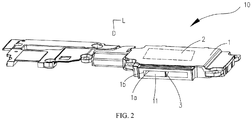
FIG. 2 is a schematic view illustrating a speaker device of the mobile terminal inFIG. 1 . -
FIG. 3 is another schematic view illustrating a speaker device of the mobile terminal inFIG. 1 . -
FIG. 4 is another schematic view illustrating a speaker device of the mobile terminal inFIG. 1 . -
FIG. 5 is yet another schematic view illustrating a speaker device of the mobile terminal inFIG. 1 . -
FIG. 6 is another schematic view illustrating a speaker device of the mobile terminal inFIG. 1 . -
FIG. 7 to FIG. 9 are schematic structural views illustrating different airflow cushion members that can be applied to the speaker device of the mobile terminal inFIG. 1 . -
FIG. 10 is a schematic view illustrating a mobile terminal according to a second implementation. -
FIG. 11 is another schematic view illustrating a speaker device of the mobile terminal inFIG. 10 . - Technical solutions embodied in implementations of the disclosure will be described in a clear and comprehensive manner in conjunction with the accompanying drawings. It is evident that the implementations described herein are merely some rather than all the implementations of the disclosure. All other implementations obtained by those of ordinary skill in the art based on the implementations of the disclosure without creative efforts shall fall within the protection scope of the disclosure.
- Referring to
FIG. 1 andFIG. 2 , amobile terminal 100 is provided according to a first implementation. Themobile terminal 100 includes aspeaker device 10. Thespeaker device 10 includes a casing 1 and anacoustic driver 2 disposed in the casing 1. The casing 1 defines asound output port 11 for outputting sound. Thesound output port 11 of the casing 1 is partially covered, enabling a reduction in an airflow velocity in thesound output port 11. - As illustrated in
FIG. 2 , the casing 1 defines thesound output port 11. Theacoustic driver 2 is fixed in the casing 1 and aligned with thesound output port 11, which facilitates sound to be output from thesound output port 11 of the casing 1. Thesound output port 11 is rectangular. Thesound output port 11 has two oppositelong edges 1a, and two oppositeshort edges 1b. Each of the twoshort edges 1b is connected between thelong edges 1a. A distance between the twolong edges 1a is defined as a width D of thesound output port 11, and a distance between the twoshort edges 1b is defined as a length L of thesound output port 11. - As illustrated in
FIG. 2 , thesound output port 11 is partially covered. The airflow velocity in thesound output port 11 of thespeaker device 10 is relatively high. By partially covering thesound output port 11, the airflow velocity in thesound output port 11 of the casing 1 is reduced, and sound distortion and doping noise are improved, such that thespeaker device 10 and themobile terminal 100 with good sound quality may be provided. - It will be appreciated that as illustrated in
FIG. 3 , thespeaker device 10 further includes anairflow cushion member 3. Theairflow cushion member 3 is disposed in thesound output port 11 of the casing 1, to partially cover thesound output port 11 of the casing 1. - To make a further improvement, as illustrated in
FIG. 3 andFIG. 4 , theairflow cushion member 3 is disposed in a middle area of thesound output port 11 along an extension direction of thelong edge 1a of thesound output port 11. From large amount of experimental data, applicant have known that an airflow velocity in the middle area of thesound output port 11 is highest, and thus distortion of audio and generation of noise can be minimized by disposing theairflow cushion member 3 in the middle area. In at least one implementation, as illustrated inFIG. 5 , theairflow cushion members 3 may also be disposed at two sides of the middle area of thesound output port 11. - In at least one implementation, as illustrated in
FIG. 3 , theairflow cushion member 3 and the casing 1 are integrally formed. That is, theairflow cushion member 3 is directly formed in the middle area of thesound output port 11 of the casing 1 in the process of forming the casing 1, which facilitates installation of thespeaker device 10. - In at least one implementation, as illustrated in
FIG. 4 , theairflow cushion member 3 is detachably coupled to thesound output port 11 of the casing 1. As one example, theairflow cushion member 3 is formed with another component. When the another component is coupled with the casing 1, theairflow cushion member 3 formed with the another component is aligned with thesound output port 11, such that theairflow cushion member 3 is detachably coupled to thesound output port 11 of the casing 1. In this case, theairflow cushion member 3 can be inserted in and coupled to thesound output port 11, or theairflow cushion member 3 can abut against edges of thesound output port 11, so that thesound output port 11 is partially covered. It is to be noted that thespeaker device 10 further includes a housing 4, that is, the another component described above is the housing 4 coupled with the casing 1. In at least one implementation, the housing 4 may be a front shell or a middle frame of themobile terminal 100. In at least one implementation, the housing 4 is provided with theairflow cushion member 3 at a position directly facing thesound output port 11, such that theairflow cushion member 3 is inserted in and coupled to thesound output port 11 of the casing 1 when the housing 4 is attached to the casing 1. In this way, thesound output port 11 is partially covered, enabling the reduction in an airflow velocity in thesound output port 11 of the casing 1 and improvement of the sound distortion and doping noise, such that aspeaker device 10 with good sound quality can be provided. - It is to be noted that as illustrated in
FIG. 3 andFIG. 4 , theairflow cushion member 3 includes at least one strip-shapedrib 31, and the at least one strip-shapedrib 31 is bridged to the twolong edges 1a. In at least one implementation, the at least one strip-shapedrib 31 is embodied as one strip-shapedrib 31, which can cover the middle area of thesound output port 11. For example, as illustrated inFIG. 3 , if theairflow cushion member 3 is directly formed with the casing 1, what needs to do is to form the strip-shapedrib 31 in the middle area of thesound output port 11 during forming the casing 1. For another example, as illustrated inFIG. 4 , if theairflow cushion member 3 is inserted in and coupled to thesound output port 11, the strip-shapedrib 31 protrudes from a position of the housing 4 aligned with the middle area of thesound output port 11. With such configuration, it is possible to make the strip-shapedrib 31 on the housing 4 be aligned with the middle area of thesound output port 11 when the housing 4 is coupled with the casing 1, such that the strip-shapedrib 31 can be cross-connected to the twolong edges 1 a of thesound output port 11. As such, thesound output port 11 may be partially covered, thereby losing the airflow velocity in thesound output port 11 of the casing 1 and improving sound distortion and doping noise, so as to provide aspeaker device 10 with good sound quality. As another example, the at least one strip-shapedrib 31 is embodied as two or three strip-shapedribs 31. Multiple strip-shapedribs 31 are centrally disposed in the middle area of thesound output port 11, and adjacent strip-shapedribs 31 are spaced apart from each other. In other examples, the at least one strip-shapedrib 31 can be in a triangle shape as illustrated inFIG. 7 , in a trapezoid shape as illustrated inFIG. 8 , or in a lightning-like shape as illustrated inFIG. 9 . -
FIG. 10 is a schematic view illustrating amobile terminal 200 according to a second implementation. Themobile terminal 200 is substantially the same as themobile terminal 100 of the first implementation, with the exception that theairflow cushion member 3 includes at least oneserration portion 32. In at least one implementation, the at least oneserration portion 32 is disposed on both of the twolong edges 1a or disposed on one of the twolong edges 1a of thesound output port 11. - As illustrated in
FIG. 10 , an edge of each of the twolong edges 1a of thesound output port 11 is provided with oneserration portion 32. Theserration portion 32 has different lengths L in the width D direction of thesound output port 11, and thus the airflow velocity can be further decreased, thereby improving the sound quality of the audio. - It should be noted that one of the two
serration portions 32 is formed on one of the twolong edges 1a of thesound output port 11, the other of the twoserration portions 32 is formed on the other of the twolong edges 1 a of thesound output port 11, and the twoserration portions 32 face each other and are spaced apart from each other. In this case, a gap between the middle area of thesound output port 11 and the twoserration portions 32 can still allow the airflow to go through. However, the airflow velocity is low, and thus the sound quality of thespeaker device 10 may not be affected. In one example, as illustrated inFIG. 11 , the twoserration portions 32 may not be spaced apart from each other, that is, the twoserration portions 32 may be coupled together to form oneserration portion 32, which is similar to the strip-shapedrib 31 of the first implementation. - According to the implementations, when using the
mobile terminal 100, the audio of themobile terminal 100 is output from thesound output port 11 of thespeaker device 10. Since thesound output port 11 of the casing 1 is partially covered, the airflow velocity in thesound output port 11 of the casing 1 may be decreased, and the sound distortion and the doping noise can be improved, thereby providing aspeaker device 10 andmobile terminal 100 with high sound quality. - The modules or units of the implementations may be combined or split according to actual needs.
- The above is implementations of the disclosure. It should be noted that those skilled in the art can also make some improvements and retouching without departing from the principles of the implementations of the disclosure. Those improvements and retouching should be considered as falling within the protection scope of the disclosure.
Claims (20)
- A speaker device, comprising:a casing; andan acoustic driver disposed in the casing;the casing defining a sound output port for outputting sound, and the sound output port of the casing being partially covered, enabling a reduction in an airflow velocity in the sound output port.
- The speaker device of claim 1, further comprising an airflow cushion member disposed in the sound output port of the casing to partially cover the sound output port of the casing.
- The speaker device of claim 1 or 2, wherein the sound output port has two opposite long edges, and two opposite short edges, wherein each of the two short edges is connected between the two long edges, wherein the sound output port has a middle area along an extension direction of the long edges, wherein the middle area is covered.
- The speaker device of claim 1 or 2, further comprising airflow cushion members disposed at two sides of a middle area of the sound output port.
- The speaker device of any of claims 2 to 4, wherein the airflow cushion member and the casing are integrally formed.
- The speaker device of claim 5, wherein the airflow cushion member comprises at least one strip-shaped rib, wherein the at least one strip-shaped rib is connected across two long edges.
- The speaker device of claim 6, wherein the at least one strip-shaped rib is embodied as one strip-shaped rib.
- The speaker device of claim 6, wherein the at least one strip-shaped rib is embodied as a plurality of strip-shaped ribs, wherein the plurality of strip-shaped ribs are centrally disposed in a middle area of the sound output port, and adjacent strip-shaped ribs are spaced apart from each other.
- The speaker device of claim 5, wherein the airflow cushion member comprises at least one serration portion, wherein the at least one serration portion is formed on both of the two long edges of the sound output port or formed on one of the two long edges of the sound output port.
- The speaker device of claim 9, wherein the at least one serration portion is embodied as two serration portions, wherein one of the two serration portions is formed on one of the two long edges of the sound output port, the other of the two serration portions is formed on the other of the two long edges of the sound output port, and the two serration portions face each other and are spaced apart from each other.
- The speaker device of claim 9, wherein the at least one serration portion is embodied as two serration portions, wherein one of the two serration portions is formed on one of the two long edges of the sound output port, the other of the two serration portions is formed on the other of the two long edges of the sound output port, and the two serration portions are coupled together.
- The speaker device of any of claims 2 to 4, wherein the airflow cushion member is detachably coupled to the sound output port of the casing.
- The speaker device of claim 12, further comprising a housing provided with the airflow cushion member at a position directly facing the sound output port, wherein the housing is attached to the casing and the airflow cushion member is inserted in and coupled to the sound output port of the casing.
- The speaker device of claim 12, wherein a housing is a front shell or a middle frame of a mobile terminal.
- The speaker device of claim 14, wherein the airflow cushion member comprises at least one strip-shaped rib, wherein the at least one strip-shaped rib is connected across two long edges.
- The speaker device of claim 15, wherein the at least one strip-shaped rib is embodied as one strip-shaped rib.
- The speaker device of claim 15, wherein the at least one strip-shaped rib is embodied as a plurality of strip-shaped ribs, wherein the plurality of strip-shaped ribs are centrally disposed in a middle area of the sound output port, and adjacent strip-shaped ribs are spaced apart from each other.
- The speaker device of claim 16 or 17, wherein the at least one strip-shaped rib protrudes from a position of the housing aligned with a middle area of the sound output port, wherein the housing is coupled with the casing, the at least one strip-shaped rib on the housing is aligned with the middle area of the sound output port, and the at least one strip-shaped rib is bridged to two long edges of the sound output port.
- The speaker device of any of claims 1 to 18, wherein the sound output port is rectangular.
- A mobile terminal comprising the speaker device of any of claims 1 to 19.
Applications Claiming Priority (3)
| Application Number | Priority Date | Filing Date | Title |
|---|---|---|---|
| CN201720789027.2U CN207783126U (en) | 2017-06-30 | 2017-06-30 | loudspeaker and mobile terminal |
| CN201710530801.2A CN107155160B (en) | 2017-06-30 | 2017-06-30 | Loudspeaker and mobile terminal |
| PCT/CN2018/091867 WO2019001310A1 (en) | 2017-06-30 | 2018-06-19 | Speaker device and mobile terminal |
Publications (2)
| Publication Number | Publication Date |
|---|---|
| EP3598775A1 true EP3598775A1 (en) | 2020-01-22 |
| EP3598775A4 EP3598775A4 (en) | 2020-03-04 |
Family
ID=64741950
Family Applications (1)
| Application Number | Title | Priority Date | Filing Date |
|---|---|---|---|
| EP18824920.5A Withdrawn EP3598775A4 (en) | 2017-06-30 | 2018-06-19 | SPEAKER DEVICE AND MOBILE DEVICE |
Country Status (3)
| Country | Link |
|---|---|
| US (1) | US11109126B2 (en) |
| EP (1) | EP3598775A4 (en) |
| WO (1) | WO2019001310A1 (en) |
Family Cites Families (16)
| Publication number | Priority date | Publication date | Assignee | Title |
|---|---|---|---|---|
| JP4572443B2 (en) * | 2000-05-15 | 2010-11-04 | 住友化学株式会社 | Thermoplastic resin foam molding for automobile interior |
| US8270660B2 (en) | 2006-07-03 | 2012-09-18 | Pioneer Corporation | Speaker device and speaker unit |
| US8112130B2 (en) * | 2008-04-01 | 2012-02-07 | Apple Inc. | Receiver acoustic system |
| US8055003B2 (en) * | 2008-04-01 | 2011-11-08 | Apple Inc. | Acoustic systems for electronic devices |
| TWM426234U (en) * | 2011-11-25 | 2012-04-01 | Comaxtech Internat Ltd | Earphone improvement structure capable of adjusting bass |
| WO2013181644A1 (en) * | 2012-06-01 | 2013-12-05 | Treefrog Developments, Inc. | Housing for an electronic device with camera, microphone and flash isolation |
| CN202799030U (en) * | 2012-08-25 | 2013-03-13 | 歌尔声学股份有限公司 | Speaker module |
| KR101498087B1 (en) * | 2013-02-21 | 2015-03-03 | 엘지전자 주식회사 | Bluetooth headset |
| CN203301682U (en) * | 2013-05-10 | 2013-11-20 | 歌尔声学股份有限公司 | Loudspeaker module |
| CN203984670U (en) * | 2014-07-24 | 2014-12-03 | 歌尔声学股份有限公司 | Microspeaker |
| US9363589B2 (en) * | 2014-07-31 | 2016-06-07 | Apple Inc. | Liquid resistant acoustic device |
| JP6655786B2 (en) * | 2015-10-30 | 2020-02-26 | パナソニックIpマネジメント株式会社 | Cordless telephone |
| CN205726426U (en) | 2016-04-25 | 2016-11-23 | 歌尔股份有限公司 | The installation housing of speaker and mike and mounting structure |
| CN206042353U (en) * | 2016-05-20 | 2017-03-22 | 歌尔股份有限公司 | Loudspeaker module |
| CN205901991U (en) * | 2016-06-30 | 2017-01-18 | 维沃移动通信有限公司 | Seal assembly and mobile terminal of speaker |
| CN107155160B (en) * | 2017-06-30 | 2020-07-28 | Oppo广东移动通信有限公司 | Loudspeaker and mobile terminal |
-
2018
- 2018-06-19 WO PCT/CN2018/091867 patent/WO2019001310A1/en not_active Ceased
- 2018-06-19 EP EP18824920.5A patent/EP3598775A4/en not_active Withdrawn
-
2019
- 2019-11-25 US US16/694,589 patent/US11109126B2/en active Active
Also Published As
| Publication number | Publication date |
|---|---|
| WO2019001310A1 (en) | 2019-01-03 |
| US20200092623A1 (en) | 2020-03-19 |
| EP3598775A4 (en) | 2020-03-04 |
| US11109126B2 (en) | 2021-08-31 |
Similar Documents
| Publication | Publication Date | Title |
|---|---|---|
| US9998809B2 (en) | Loudspeaker module | |
| US10567858B2 (en) | Loudspeaker module and terminal device | |
| US10715899B2 (en) | Wind noise prevention microphone and earphone cable control apparatus | |
| US10045108B2 (en) | Earphone device with a microphone | |
| JP6954578B2 (en) | Audio components and mobile devices | |
| US8073177B2 (en) | Film-type audio output apparatus | |
| US10932033B2 (en) | Speaker box | |
| CN112533113A (en) | Loudspeaker and terminal | |
| CN205142450U (en) | Loudspeaker module shell and loudspeaker module | |
| CN108039559A (en) | Metal base, center component and electronic equipment | |
| CN207884689U (en) | Anti-blocking sound output structure of mobile terminal | |
| CN103354629B (en) | Speaker module | |
| US20120160599A1 (en) | Sound box and electronic device using same | |
| US11109126B2 (en) | Speaker device and terminal | |
| WO2024037039A1 (en) | Sound generation device and electronic device | |
| CN101442694B (en) | Loudspeaker assembly | |
| CN203661138U (en) | Casing assembly, handset and mobile terminal | |
| CN107634409B (en) | Sound generating device module and electronic equipment | |
| CN103139680A (en) | Electronic equipment | |
| CN209358758U (en) | A kind of arc loudspeaker box structure | |
| CN107155160B (en) | Loudspeaker and mobile terminal | |
| US4029910A (en) | Wide dispersion loudspeaker with flexing diaphragm | |
| CN207783126U (en) | loudspeaker and mobile terminal | |
| CN104902407A (en) | Horn type micro loudspeaker and terminal equipment | |
| CN211152196U (en) | Sound cavity device and mobile terminal |
Legal Events
| Date | Code | Title | Description |
|---|---|---|---|
| STAA | Information on the status of an ep patent application or granted ep patent |
Free format text: STATUS: THE INTERNATIONAL PUBLICATION HAS BEEN MADE |
|
| PUAI | Public reference made under article 153(3) epc to a published international application that has entered the european phase |
Free format text: ORIGINAL CODE: 0009012 |
|
| STAA | Information on the status of an ep patent application or granted ep patent |
Free format text: STATUS: REQUEST FOR EXAMINATION WAS MADE |
|
| 17P | Request for examination filed |
Effective date: 20191017 |
|
| AK | Designated contracting states |
Kind code of ref document: A1 Designated state(s): AL AT BE BG CH CY CZ DE DK EE ES FI FR GB GR HR HU IE IS IT LI LT LU LV MC MK MT NL NO PL PT RO RS SE SI SK SM TR |
|
| AX | Request for extension of the european patent |
Extension state: BA ME |
|
| A4 | Supplementary search report drawn up and despatched |
Effective date: 20200205 |
|
| RIC1 | Information provided on ipc code assigned before grant |
Ipc: H04R 1/28 20060101ALI20200130BHEP Ipc: H04R 9/06 20060101AFI20200130BHEP Ipc: H04R 1/02 20060101ALN20200130BHEP |
|
| STAA | Information on the status of an ep patent application or granted ep patent |
Free format text: STATUS: EXAMINATION IS IN PROGRESS |
|
| 17Q | First examination report despatched |
Effective date: 20200819 |
|
| DAV | Request for validation of the european patent (deleted) | ||
| DAX | Request for extension of the european patent (deleted) | ||
| STAA | Information on the status of an ep patent application or granted ep patent |
Free format text: STATUS: THE APPLICATION HAS BEEN WITHDRAWN |
|
| 18W | Application withdrawn |
Effective date: 20230421 |