EP3598610A1 - Rotor for dynamo-electric machine, and dynamo-electric machine - Google Patents
Rotor for dynamo-electric machine, and dynamo-electric machine Download PDFInfo
- Publication number
- EP3598610A1 EP3598610A1 EP18767351.2A EP18767351A EP3598610A1 EP 3598610 A1 EP3598610 A1 EP 3598610A1 EP 18767351 A EP18767351 A EP 18767351A EP 3598610 A1 EP3598610 A1 EP 3598610A1
- Authority
- EP
- European Patent Office
- Prior art keywords
- rotor
- protruding portion
- slot
- permanent magnet
- magnet
- Prior art date
- Legal status (The legal status is an assumption and is not a legal conclusion. Google has not performed a legal analysis and makes no representation as to the accuracy of the status listed.)
- Withdrawn
Links
Images






Classifications
-
- H—ELECTRICITY
- H02—GENERATION; CONVERSION OR DISTRIBUTION OF ELECTRIC POWER
- H02K—DYNAMO-ELECTRIC MACHINES
- H02K1/00—Details of the magnetic circuit
- H02K1/06—Details of the magnetic circuit characterised by the shape, form or construction
- H02K1/22—Rotating parts of the magnetic circuit
- H02K1/27—Rotor cores with permanent magnets
- H02K1/2706—Inner rotors
- H02K1/272—Inner rotors the magnetisation axis of the magnets being perpendicular to the rotor axis
- H02K1/274—Inner rotors the magnetisation axis of the magnets being perpendicular to the rotor axis the rotor consisting of two or more circumferentially positioned magnets
- H02K1/2753—Inner rotors the magnetisation axis of the magnets being perpendicular to the rotor axis the rotor consisting of two or more circumferentially positioned magnets the rotor consisting of magnets or groups of magnets arranged with alternating polarity
- H02K1/276—Magnets embedded in the magnetic core, e.g. interior permanent magnets [IPM]
- H02K1/2766—Magnets embedded in the magnetic core, e.g. interior permanent magnets [IPM] having a flux concentration effect
-
- H—ELECTRICITY
- H02—GENERATION; CONVERSION OR DISTRIBUTION OF ELECTRIC POWER
- H02K—DYNAMO-ELECTRIC MACHINES
- H02K1/00—Details of the magnetic circuit
- H02K1/06—Details of the magnetic circuit characterised by the shape, form or construction
- H02K1/22—Rotating parts of the magnetic circuit
- H02K1/27—Rotor cores with permanent magnets
- H02K1/2706—Inner rotors
- H02K1/272—Inner rotors the magnetisation axis of the magnets being perpendicular to the rotor axis
- H02K1/274—Inner rotors the magnetisation axis of the magnets being perpendicular to the rotor axis the rotor consisting of two or more circumferentially positioned magnets
- H02K1/2753—Inner rotors the magnetisation axis of the magnets being perpendicular to the rotor axis the rotor consisting of two or more circumferentially positioned magnets the rotor consisting of magnets or groups of magnets arranged with alternating polarity
- H02K1/276—Magnets embedded in the magnetic core, e.g. interior permanent magnets [IPM]
-
- H—ELECTRICITY
- H02—GENERATION; CONVERSION OR DISTRIBUTION OF ELECTRIC POWER
- H02K—DYNAMO-ELECTRIC MACHINES
- H02K1/00—Details of the magnetic circuit
- H02K1/06—Details of the magnetic circuit characterised by the shape, form or construction
- H02K1/22—Rotating parts of the magnetic circuit
- H02K1/28—Means for mounting or fastening rotating magnetic parts on to, or to, the rotor structures
-
- H—ELECTRICITY
- H02—GENERATION; CONVERSION OR DISTRIBUTION OF ELECTRIC POWER
- H02K—DYNAMO-ELECTRIC MACHINES
- H02K2201/00—Specific aspects not provided for in the other groups of this subclass relating to the magnetic circuits
- H02K2201/06—Magnetic cores, or permanent magnets characterised by their skew
Definitions
- the present invention relates to a rotor of a rotary electric machine, and a rotary electric machine which includes the rotor.
- a rotor of a permanent magnet embedded type As one of rotors of a rotary electric machine, there is a rotor of a permanent magnet embedded type (for example, see PTL 1).
- a permanent magnet of which the cross section is rectangular is disposed in a hole for embedding the permanent magnet formed in the rotor.
- An elastic fixing projection is formed in the hole for embedding the permanent magnet is formed in each of two side surfaces of magnet which are provided in a longitudinal direction and face each other. The elastic fixing projection is pressed to position and fix the permanent magnet in the longitudinal direction.
- the elastic fixing projection is elastically deformed by a centrifugal force operating on the permanent magnet, and the permanent magnet may move in the longitudinal direction.
- the shape and the displacement of the permanent magnet are ideally bisymmetrical to a radius passing a gravity center of the permanent magnet, the component of the centrifugal force in the longitudinal direction of the magnet becomes zero.
- exact bisymmetry is hardly obtained due to an actual machining tolerance, and the component of the centrifugal force in the longitudinal direction of the magnet does not become zero.
- a rotor of a rotary electric machine where a permanent magnet is disposed in a slot for storing a magnet of a rotor core, wherein the permanent magnet is an angulated pillar member of which a cross section perpendicular to a rotor shaft center is rectangular, and includes two pairs of facing side surfaces which extend along the rotor shaft center, the paired-up side surfaces are provided such that one side surface is provided on a side near the rotor shaft center, and the other one is provided on an outer peripheral side of the rotor, in the slot for storing a magnet, a first protruding portion is provided which protrudes from an inner peripheral surface of the slot and abuts on a side surface on a side near the rotor shaft center of any pair of side surfaces in the two pairs, and the first protruding portion applies, to the permanent magnet, the urging force in which a first component force in an outer peripheral direction of the rotor along the abutting side surface and
- the rotary electric machine includes a stator and the above described rotor.
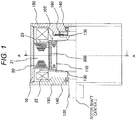
- FIG. 1 is a cross-sectional view illustrating an embodiment of a rotary electric machine.
- a stator 20 is supported in a housing 10.
- the stator 20 includes a stator core 21 and a stator winding 22.
- a rotor 100 is rotatably supported through a gap 23.
- the rotor 100 includes a rotor core 110 fixed to a shaft 120, a permanent magnet 300, and a plate 130 of a non-magnetic material.
- the housing 10 includes a pair of end brackets 150 where a bearing 140 is provided, and the shaft 120 is rotatably supported by the bearings 140.
- a resolver 160 to detect a position of the pole of the rotor 100 and a rotation speed.
- FIG. 2 is a diagram illustrating a cross section (a cross section taken along A-A of FIG. 1 ) of the rotor 100.
- Magnet storage slots 200A and 200B are formed in the rotor 100.
- a pair of permanent magnets 300 is fixed to the magnet storage slots 200A and 200B in a V shape.
- One magnetic pole is configured by the pair of permanent magnets 300.
- FIG. 3 is an enlarged view illustrating a portion (a portion indicated with Symbol B) of the magnet storage slot 200A where the permanent magnet 300 of FIG. 2 is disposed. Further, the shape of each portion of the magnet storage slot 200B is bisymmetrical to the magnet storage slot 200A. In the following, the description will be given about the magnet storage slot 200A.
- a protruding portion 210 is formed to protrude from the inner peripheral surface of the slot.
- the cross section of the permanent magnet 300 is almost a rectangular shape, and forms an angulated pillar member having four side surfaces 310, 320, 330, and 340. The side surfaces 310, 320, 330, and 340 are formed along a rotor shaft center J of FIG. 1 .
- the protruding portion 210 abuts on the side surface 310 of the permanent magnet 300, and urges the permanent magnet 300 to an outer peripheral direction of the rotor with an urging force F.
- the side surface 320 is provided to face the side surface 310 abutting on the protruding portion 210.
- a pair of facing side surfaces 330 and 340 is provided to connect the side surface 310 and the side surface 320.
- the side surface 320 is disposed on the outer peripheral side of the rotor from the side surface 310.
- the side surface 330 is disposed on the outer peripheral side of the rotor from the side surface 340.
- a gap is formed such that the protruding portion 210 does not come in contact with the side surface 310 of the permanent magnet 300 when the permanent magnet 300 is stored in the magnet storage slot 200A. As described below, after storing the permanent magnet 300, the protruding portion 210 is bent and abuts on the side surface 310 to fix the permanent magnet 300.
- the urging force F operating from the protruding portion 210 to the permanent magnet 300 can be decomposed into a component force F1 in a longitudinal direction of the permanent magnet 300 and a component force F2 in a lateral direction (thickness direction).
- the permanent magnet 300 is urged to the outer peripheral side of the rotor in the longitudinal direction by the component force F1.
- the side surface 320 corresponds to a positioning portion 230 formed in the magnet storage slot 200A.
- the positioning in the longitudinal direction of the permanent magnet 300 is performed.
- the permanent magnet 300 is urged to the outer peripheral side of the rotor by the component force F2.
- the side surface 330 abuts on a wall surface 240 of the outer peripheral side of the rotor of the magnet storage slot 200. With this configuration, the positioning of the lateral direction of the permanent magnet 300 is performed.
- the wall surface 240 serves as a second positioning portion related to the lateral direction of the permanent magnet 300.
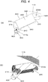
- FIG. 4 is a diagram for describing an example of bending machining of the protruding portion 210 using a tool.
- the permanent magnet 300 is inserted into the magnet storage slot 200A.
- the protruding portion 210 is not bent, and a gap is formed between the protruding portion 210 and the side surface 310 of the permanent magnet 300.
- a rod-like deformed tool 500 is inserted to a tool insertion space 400 on a side near a rotor shaft center from the protruding portion 210 of the magnet storage slot 200. Thereafter, as illustrated with an arrow of FIG. 4(a) , the deformed tool 500 is moved to the outer peripheral side of the rotor. As illustrated with a broken line, the root portion of the protruding portion 210 is elastically deformed to bend the protruding portion 210 in a direction of the side surface 310 of the permanent magnet 300.
- the elastic force caused by the elastic deformation of the tip of the protruding portion (the urging force F illustrated in FIG. 3 ) elastically deforms the root portion furthermore by the operation of the permanent magnet 300.
- the side surface 320 of the permanent magnet 300 abuts on the positioning portion 230, and the side surface 330 abuts on the wall surface 240.
- the permanent magnet 300 is fixed into the magnet storage slot 200A of the rotor core 110.
- the urging force F operating from the protruding portion 210 to the permanent magnet 300 faces the outer peripheral direction of the rotor. Therefore, the permanent magnet 300 is configured such that the side surfaces 320 and 330 on the outer peripheral side of the rotor abut on the positioning portion 230 and the wall surface 240 respectively. Therefore, even when a centrifugal force operates on the permanent magnet 300 when the rotor rotates, the permanent magnet does not move in the longitudinal direction and the lateral direction, so that abrasion is prevented between the permanent magnet 300 and the rotor core 110.
- a protrusion 210a which protrudes toward the tool insertion space 400 is formed in the tip of the protruding portion 210, and the surface of the protruding portion 210 on a side near the space 400 is formed in an arc shape. Therefore, when the protruding portion 210 is bent, the deformed tool 500 is securely engaged by the protrusion 210a. Therefore, a workability of bending process of the deformed tool 500 is improved.
- the permanent magnet 300 is an angulated pillar member of which the cross section perpendicular to the rotor shaft center is rectangular, includes two pairs of facing side surfaces 310, 320, 330, and 340 extending along the rotor shaft center.
- the paired-up side surfaces 310 and 320 one side surface 310 is provided on a side near the rotor shaft center, and the other side surface 320 is provided on the outer peripheral side of the rotor.
- the protruding portion 210 which protrudes from the inner peripheral surface of the slot and abuts on the side surface 310 on a side near the rotor shaft center of any pair of side surfaces 310 and 320 in the two pairs.
- the protruding portion 210 applies, to the permanent magnet 300, the urging force F of which the component force F2 of the outer peripheral direction of the rotor along the abutting side surface 310 and the component force F1 of the outer peripheral direction of the rotor along the side surface 340 adjacent to the abutting side surface 310 are not zero.
- the protruding portion 210 applies the urging force F which can be decomposed into the component forces F1 and F2 to the permanent magnet 300.
- the permanent magnet 300 is positioned to abut on the positioning portion 230 and the wall surface 240 on the outer peripheral side of the rotor. Therefore, even in a case where the centrifugal force caused by the rotation of the rotor operates on the permanent magnet 300, the component forces F1 and F2 are not cancelled by the centrifugal force, a positional deviation (that is, movement) of the permanent magnet 300 in the magnet storage slot 200A can be prevented, and abrasion between the magnet and the rotor core can be prevented.
- the tool insertion space 400 is provided to deform the protruding portion 210 to a side near the rotor shaft center from the protruding portion 210. Therefore, the deforming process of the protruding portion 210 can be made easily using the deformed tool 500, and the working efficiency can be improved.
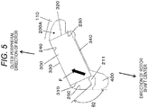
- FIG. 5 is a diagram illustrating a first modification of the embodiment.
- a protruding portion 211 illustrated in FIG. 5 is provided instead of the protruding portion 210 illustrated in FIG. 3 .
- an angle ⁇ 1 formed with the wall surface 250 of the magnet storage slot 200A which faces the side surface 310 of the permanent magnet 300 is an acute angle.
- an angle ⁇ 2 is not an obtuse angle.
- the protruding portion 211 having such a shape abuts on the side surface 310 of the permanent magnet 300, and the urging force F of the outer peripheral direction of the rotor operates on the permanent magnet 300.
- the permanent magnet 300 does not move in the longitudinal direction and the lateral direction when the rotor rotates, so that abrasion can be prevented between the permanent magnet 300 and the rotor core 110.
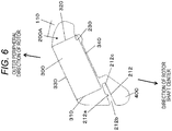
- FIG. 6 is a diagram illustrating a second modification of the embodiment.
- the shape of a protruding portion 212 is different from those of the protruding portions 210 and 211 illustrated in FIGS. 3 and 5 .
- the configurations other than the protruding portion 212 are similar to those of the embodiment.
- the protruding portion 212 includes a concave portion 212a which is formed in the side surface of the protruding portion 212, an elastically deforming portion 212b which is formed on the inner peripheral surface side of the slot from the concave portion 212a, and an abutting portion 212c which is formed on a tip side from the concave portion 212a.
- FIG. 6 illustrates a shape before the protruding portion 212 is deformed to abut on the side surface 310 of the permanent magnet 300.
- FIG. 7 is a diagram for describing a process in which the protruding portion 212 is deformed to abut on the side surface 310 of the permanent magnet 300.
- the deformed tool 500 is pressed to the elastically deforming portion 212b of the protruding portion 212 to press the protruding portion 212 in a direction of arrow.
- the root portion (a portion indicated with Symbol C) of the elastically deforming portion 212b is elastically deformed, and the abutting portion 212c abuts on the side surface 340 of the permanent magnet 300.
- the elastically deforming portion 212b when the elastically deforming portion 212b is pressed and bent furthermore from the state of FIG. 7(a) , the concave portion 212a is elastically deformed. As a result, the urging force F elastically deforming the protruding portion 212 operates on the permanent magnet 300.
- the abutting portion 212c abuts on a corner (a portion of Symbol D) where the side surface 310 and the side surface 340 intersects, and the urging force F operates on the outer peripheral direction of the rotor.
- the urging force F can be decomposed into the component forces F1 and F2.
- the side surface 330 of the permanent magnet 300 abuts on the wall surface 240 on the outer peripheral side of the rotor of the magnet storage slot 200 by the component force F2.
- the side surface 320 of the permanent magnet 300 abuts on the positioning portion 230 by the component force F1.
- the permanent magnet 300 is fixed into the magnet storage slot 200A.
- the protruding portion 212 in the second modification includes, as illustrated in FIG. 7 , the concave portion 212a which is formed between the inner peripheral surface side of the slot and the tip side of the rotor, the elastically deforming portion 212b on the inner peripheral surface side of the slot from the concave portion 212a, and the abutting portion 212c on the tip side from the concave portion 212a.
- the elastic force generated by the elastic deformation of the concave portion 212a operates on the permanent magnet 300 as the urging force F.
- the pressing portion 212a is provided in the protruding portion 212, so that the bending amount of the concave portion 212a is adjusted even though a variation of the gap is large. Therefore, the abutting portion 212c can come into contact with the permanent magnet 300 with a desired urging force. In other words, with the concave portion 212a, the elastic force can be kept less even the bending amount is large. Even in a case where the gap is large and thus the bending amount is large, the urging force operating on the permanent magnet 300 can be prevented from being too much.
- FIG. 8 is a diagram illustrating a second embodiment of the invention.
- the fixation to the magnet storage slots 200A and 200B of the permanent magnet 300 is made using two protruding portions 212 and 213.
- the configurations other than the protruding portions 212 and 213 are similar to those illustrated in FIG. 6 .
- the shape of the protruding portion 213 is similar to the protruding portion 212, and includes a concave portion 213a which is formed in the side surface of the protruding portion 213, an elastically deforming portion 213b which is formed on the inner peripheral surface side of the slot from the concave portion 213a, and an abutting portion 213c which is formed on a tip side from the concave portion 213a.
- FIG. 8 illustrates a state before the protruding portions 212 and 213 are deformed, and become the shape illustrated in FIG. 9 after deformation.
- the protruding portion 212 is configured such that the concave portion 212a is elastically deformed to cause the abutting portion 212c to abut on the side surface 340 of the permanent magnet 313 similarly to the case of FIG. 7(b) .
- the protruding portion 213 is configured such that the concave portion 213a is elastically deformed to cause the abutting portion 213c to abut on the side surface 310 of the permanent magnet 300.
- a force F obtained by combining the elastic force operating from the protruding portions 212 and 213 to the permanent magnet 300 operates on the permanent magnet 300 as the urging force of the outer peripheral direction of the rotor.
- the urging force F in this case is a resultant force of the urging force of the protruding portion 212 and the urging force of the protruding portion 213. Then, the side surface 330 of the permanent magnet 300 abuts on the wall surface 240 on the outer peripheral side of the rotor of the magnet storage slot 200 by the component force F2 of the urging force F. The side surface 320 of the permanent magnet 300 abuts on the positioning portion 230 by the component force F1.
- the protruding portion 213 is further provided, so that the urging force (the component forces F1 and F2) causing the permanent magnet 300 to abut on the positioning portion 230 and the wall surface 240 on the outer peripheral side of the rotor can be made large compared to the case of the second modification illustrated in FIG. 6 .
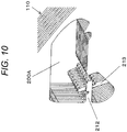
- FIG. 10 is a perspective view specifically illustrating the shape of the rotor core 110 of the magnet storage slot 200A.
- the rotor core 110 is formed by stacking a plurality of rotor core steel plates 110a illustrated in FIG. 11 .
- two types of slot opening pairs 201 and 202 to dispose the permanent magnet 300 in a V shape are formed in the rotor core steel plate 110a to be alternately disposed at a magnetic pole pitch ⁇ in a circumferential direction of the rotor core steel plate 110a.
- FIG. 11(b) illustrates that the rotor core steel plate 110a illustrated in FIG. 11(a) is deviated by a phase of the magnetic pole pitch ⁇ (that is, rotated by the magnetic pole pitch ⁇ ).
- the displacement of FIG. 11(a) will be called a first displacement
- the displacement will illustrated in FIG. 11(b) will be called a second displacement.
- a pair of slot openings 201a and 201b forming the slot opening pair 201 is formed bisymmetrically with respect to a radius J1 which passes through a magnetic pole position.
- the protruding portion 212 formed in the slot openings 201a and 201b are also formed at positions symmetrical with respect to the radius J1.
- a pair of slot openings 202a and 202b forming the slot opening pair 202 is formed bisymmetrically with respect to a radius J2 which passes through a magnetic pole position.
- the protruding portion 213 formed in the slot openings 202a and 202b are also formed at positions symmetrical with respect to the radius J2.
- the rotor core steel plate 110a of the first displacement illustrated in FIG. 11(a) and the rotor core steel plate 110a of the second displacement illustrated in FIG. 11(b) are alternately stacked so as to form the rotor core 110 as illustrated in FIG. 12 .
- the slot opening 202a formed in the rotor core steel plate 110a of the second displacement is disposed at the same position as the slot opening 201a formed in the rotor core steel plate 110a of the first displacement, facing each other.
- there is formed the magnet storage slot 200A which includes the protruding portions 212 and 213.
- the slot opening 202b formed in the rotor core steel plate 110a of the second displacement is disposed at the same position as the slot opening 201b formed in the rotor core steel plate 110a of the first displacement, facing each other.
- the magnet storage slot 200B which includes the protruding portions 212 and 213.
- the magnet storage slot 200A is provided with a second protruding portion 213 which protrudes from the inner peripheral surface of the slot and abuts on the side surface 310 on a side near the rotor shaft center of the other pair of side surfaces 310 and 320.
- the protruding portion 213 applies, to the permanent magnet 300, the urging force F of which the component force F2 of the outer peripheral direction of the rotor along the abutting side surface 310 and the component force F1 of the outer peripheral direction of the rotor along the side surface 340 adjacent to the abutting side surface 310 are not zero.
- the slot opening 201a formed with the protruding portion 212 and the slot opening 202a which is provided to be deviated from the slot opening 201a by the magnetic pole pitch ⁇ and includes the protruding portion 213 are formed alternately in the circumferential direction. Then, the plurality of rotor core steel plates 110a forming the rotor core 110 are alternately stacked such that the slot opening 201a and the slot opening 202a face each other.
- the slot openings 201a and 201b where the protruding portion 212 is formed and the slot openings 202a and 202b where the protruding portion 213 is formed are adjacent in the stacking direction in the same rotor core steel plate 110a, and the rotor core steel plate 110a adjacent in the stacking direction is stacked to be deviated by the magnetic pole pitch ⁇ . Therefore, it is possible to easily form the magnet storage slots 200A and 200B which include the two protruding portions 212 and 213 using one type of rotor core steel plate 110a.
- FIG. 13 is a diagram illustrating a third modification which is a modification of the second embodiment.
- a protruding portion 214 and a protruding portion 215 are formed in the same rotor core steel plate.
- the shape of the protruding portion 214 is made in a shape similar to the protruding portion 210 illustrated in FIG. 3 , and moves the deformed tool 500 in a direction of arrow R1 with respect to the protruding portion 214, so that the tip portion of the protruding portion 214 abuts on the side surface 310 of the permanent magnet 300.
- the protruding portion 215 is formed in a shape bisymmetrical to the protruding portion 214, and moves the deformed tool 500 in a direction of arrow R2 with respect to the protruding portion 215, so that the tip portion of the protruding portion 215 abuts on the side surface 340 of the permanent magnet 300.
- the urging force F is a force obtained by combining the urging force caused by the protruding portion 214 and the urging force caused by the protruding portion 215.
- the side surface 320 of the permanent magnet 300 abuts on the positioning portion 230 by the component force F1 of the urging force F.
- the side surface 330 of the permanent magnet 300 abuts on the wall surface 240 of the magnet storage slot 200A by the component force F2.
- the permanent magnet 300 is fixed into the magnet storage slot 200A.
- the protruding portions 214 and 215 are formed in the same rotor core steel plate. Therefore, like the case of the configuration illustrated in FIG. 11 , there is no need to deviate the phase when stacking the rotor core steel plates by the magnetic pole pitch ⁇ .
- the description in the embodiment has been given about a case where the permanent magnets 300 are disposed in a V shape.
- the invention may be applied similarly even to a configuration where a pair of permanent magnets 300 is disposed on a straight line.
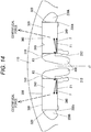
- the magnet storage slots 200A and 200B are disposed on a straight line bisymmetrically with respect to the radius J1 passing the magnetic pole position.
- the protruding portion 212 abuts on near the corner formed by the side surface 310 and the side surface 340 of the permanent magnet 300, and applies the urging force F in the outer diameter direction of the rotor with respect to the permanent magnet 300.
- the permanent magnet 300 is formed such that the side surface 320 abuts on the positioning portion 230 by the component force F1, and the side surface 330 abuts on a wall surface 340 by the component force F2.
- the centrifugal force added to the permanent magnet 300 operates in the radius direction from the gravity center of the permanent magnet when the rotor rotate as illustrated with a broken arrow, so that the permanent magnet 300 is urged to the positioning portion 230 and the wall surface 240. Therefore, similarly to the case of the embodiment, the abrasion between the magnet and the rotor core caused by the influence of the centrifugal force can be prevented.
- the example illustrated in FIG. 14 has described a case where one protruding portion 212 is provided in the magnet storage slots 200A and 200B.
- the two protruding portions 211 and 213 may be provided similarly to the case illustrated in FIG. 9 .
- the protruding portions 210, 211, 214, and 215 may be provided as illustrated in FIGS. 4 , 5 , and 13 .
Landscapes
- Engineering & Computer Science (AREA)
- Power Engineering (AREA)
- Permanent Field Magnets Of Synchronous Machinery (AREA)
Abstract
Description
- The present invention relates to a rotor of a rotary electric machine, and a rotary electric machine which includes the rotor.
- As one of rotors of a rotary electric machine, there is a rotor of a permanent magnet embedded type (for example, see PTL 1). In the rotor of the permanent magnet embedded type disclosed in PTL 1, a permanent magnet of which the cross section is rectangular is disposed in a hole for embedding the permanent magnet formed in the rotor. An elastic fixing projection is formed in the hole for embedding the permanent magnet is formed in each of two side surfaces of magnet which are provided in a longitudinal direction and face each other. The elastic fixing projection is pressed to position and fix the permanent magnet in the longitudinal direction.
- PTL 1:
JP 2011-259610 A - However, when the rotor rotates, the elastic fixing projection is elastically deformed by a centrifugal force operating on the permanent magnet, and the permanent magnet may move in the longitudinal direction. Further, in the case of the configuration of the rotor described in PTL 1, if the shape and the displacement of the permanent magnet are ideally bisymmetrical to a radius passing a gravity center of the permanent magnet, the component of the centrifugal force in the longitudinal direction of the magnet becomes zero. However, exact bisymmetry is hardly obtained due to an actual machining tolerance, and the component of the centrifugal force in the longitudinal direction of the magnet does not become zero.
- Therefore, a movement in the longitudinal direction of the permanent magnet occurs, and abrasion between the magnet and the rotor core causes a problem. In particular, in a case where the magnet fixing method described in PTL 1 is applied to a rotor in which the permanent magnets are disposed in a V shape, the component of the centrifugal force in the longitudinal direction of the magnet does not become zero in the V-like layout. Thus, the abrasion is inevitable.
- According to an aspect of the invention, there is provided a rotor of a rotary electric machine where a permanent magnet is disposed in a slot for storing a magnet of a rotor core, wherein the permanent magnet is an angulated pillar member of which a cross section perpendicular to a rotor shaft center is rectangular, and includes two pairs of facing side surfaces which extend along the rotor shaft center, the paired-up side surfaces are provided such that one side surface is provided on a side near the rotor shaft center, and the other one is provided on an outer peripheral side of the rotor, in the slot for storing a magnet, a first protruding portion is provided which protrudes from an inner peripheral surface of the slot and abuts on a side surface on a side near the rotor shaft center of any pair of side surfaces in the two pairs, and the first protruding portion applies, to the permanent magnet, the urging force in which a first component force in an outer peripheral direction of the rotor along the abutting side surface and a second component force in the outer peripheral direction of the rotor along the side surface adjacent to the abutting side surface are not zero.
- According to another aspect of the invention, the rotary electric machine includes a stator and the above described rotor.
- According to the invention, it is possible to prevent abrasion between a magnet and a rotor core caused by a centrifugal force.
-
- [
FIG. 1] FIG. 1 is a cross-sectional view illustrating an embodiment of a rotary electric machine. - [
FIG. 2] FIG. 2 is a diagram illustrating a cross section of a rotor. - [
FIG. 3] FIG. 3 is an enlarged view of Symbol B ofFIG. 2 . - [
FIG. 4] FIG. 4 is a diagram for describing an example of bending machining of a protruding portion using a tool. - [
FIG. 5] FIG. 5 is a diagram illustrating a first modification. - [
FIG. 6] FIG. 6 is a diagram illustrating a second modification. - [
FIG. 7] FIG. 7 is a diagram for describing a process in which the protruding portion is deformed to abut on the side surface of a permanent magnet. - [
FIG. 8] FIG. 8 is a diagram illustrating a second embodiment of the invention. - [
FIG. 9] FIG. 9 is a diagram illustrating the protruding portion after deformation. - [
FIG. 10] FIG. 10 is a perspective view specifically illustrating a shape of a magnet storage slot. - [
FIG. 11] FIG. 11 is a diagram for describing a stacking method of rotor core steel plates. - [
FIG. 12] FIG. 12 is a diagram illustrating a part of a rotor core in which the magnet storage slots, each having two protruding portions, are disposed in a V shape. - [
FIG. 13] FIG. 13 is a diagram illustrating a third modification. - [
FIG. 14] FIG. 14 is a diagram illustrating a case where two permanent magnets forming a magnetic pole are disposed in a straight line. - Hereinafter, embodiments of the invention will be described with reference to the drawings.
-
FIG. 1 is a cross-sectional view illustrating an embodiment of a rotary electric machine. Astator 20 is supported in ahousing 10. Thestator 20 includes astator core 21 and a stator winding 22. On an inner peripheral side of thestator core 21, arotor 100 is rotatably supported through agap 23. Therotor 100 includes arotor core 110 fixed to ashaft 120, apermanent magnet 300, and aplate 130 of a non-magnetic material. Thehousing 10 includes a pair ofend brackets 150 where abearing 140 is provided, and theshaft 120 is rotatably supported by thebearings 140. In theshaft 120, there is provided aresolver 160 to detect a position of the pole of therotor 100 and a rotation speed. -
FIG. 2 is a diagram illustrating a cross section (a cross section taken along A-A ofFIG. 1 ) of therotor 100.Magnet storage slots rotor 100. A pair ofpermanent magnets 300 is fixed to themagnet storage slots permanent magnets 300. -
FIG. 3 is an enlarged view illustrating a portion (a portion indicated with Symbol B) of themagnet storage slot 200A where thepermanent magnet 300 ofFIG. 2 is disposed. Further, the shape of each portion of themagnet storage slot 200B is bisymmetrical to themagnet storage slot 200A. In the following, the description will be given about themagnet storage slot 200A. In themagnet storage slot 200A, a protrudingportion 210 is formed to protrude from the inner peripheral surface of the slot. The cross section of thepermanent magnet 300 is almost a rectangular shape, and forms an angulated pillar member having fourside surfaces side surfaces FIG. 1 . - The protruding
portion 210 abuts on theside surface 310 of thepermanent magnet 300, and urges thepermanent magnet 300 to an outer peripheral direction of the rotor with an urging force F. Theside surface 320 is provided to face theside surface 310 abutting on the protrudingportion 210. In addition, a pair of facingside surfaces side surface 310 and theside surface 320. Theside surface 320 is disposed on the outer peripheral side of the rotor from theside surface 310. Theside surface 330 is disposed on the outer peripheral side of the rotor from theside surface 340. - Further, a gap is formed such that the
protruding portion 210 does not come in contact with theside surface 310 of thepermanent magnet 300 when thepermanent magnet 300 is stored in themagnet storage slot 200A. As described below, after storing thepermanent magnet 300, the protrudingportion 210 is bent and abuts on theside surface 310 to fix thepermanent magnet 300. - The urging force F operating from the protruding
portion 210 to thepermanent magnet 300 can be decomposed into a component force F1 in a longitudinal direction of thepermanent magnet 300 and a component force F2 in a lateral direction (thickness direction). Thepermanent magnet 300 is urged to the outer peripheral side of the rotor in the longitudinal direction by the component force F1. Theside surface 320 corresponds to apositioning portion 230 formed in themagnet storage slot 200A. As a result, the positioning in the longitudinal direction of thepermanent magnet 300 is performed. In addition, thepermanent magnet 300 is urged to the outer peripheral side of the rotor by the component force F2. Theside surface 330 abuts on awall surface 240 of the outer peripheral side of the rotor of the magnet storage slot 200. With this configuration, the positioning of the lateral direction of thepermanent magnet 300 is performed. In other words, thewall surface 240 serves as a second positioning portion related to the lateral direction of thepermanent magnet 300. -
FIG. 4 is a diagram for describing an example of bending machining of the protrudingportion 210 using a tool. First, as illustrated inFIG. 4(a) , thepermanent magnet 300 is inserted into themagnet storage slot 200A. At that time point, the protrudingportion 210 is not bent, and a gap is formed between the protrudingportion 210 and theside surface 310 of thepermanent magnet 300. - Next, as illustrated in
FIG. 4(b) , a rod-likedeformed tool 500 is inserted to atool insertion space 400 on a side near a rotor shaft center from the protrudingportion 210 of the magnet storage slot 200. Thereafter, as illustrated with an arrow ofFIG. 4(a) , thedeformed tool 500 is moved to the outer peripheral side of the rotor. As illustrated with a broken line, the root portion of the protrudingportion 210 is elastically deformed to bend the protrudingportion 210 in a direction of theside surface 310 of thepermanent magnet 300. At that time, even after the tip of the protrudingportion 210 comes into contact with theside surface 310, the elastic force caused by the elastic deformation of the tip of the protruding portion (the urging force F illustrated inFIG. 3 ) elastically deforms the root portion furthermore by the operation of thepermanent magnet 300. As a result, theside surface 320 of thepermanent magnet 300 abuts on thepositioning portion 230, and theside surface 330 abuts on thewall surface 240. With this configuration, thepermanent magnet 300 is fixed into themagnet storage slot 200A of therotor core 110. - As illustrated in
FIG. 3 , the urging force F operating from the protrudingportion 210 to thepermanent magnet 300 faces the outer peripheral direction of the rotor. Therefore, thepermanent magnet 300 is configured such that the side surfaces 320 and 330 on the outer peripheral side of the rotor abut on thepositioning portion 230 and thewall surface 240 respectively. Therefore, even when a centrifugal force operates on thepermanent magnet 300 when the rotor rotates, the permanent magnet does not move in the longitudinal direction and the lateral direction, so that abrasion is prevented between thepermanent magnet 300 and therotor core 110. - Further, as illustrated in
FIG. 4 , aprotrusion 210a which protrudes toward thetool insertion space 400 is formed in the tip of the protrudingportion 210, and the surface of the protrudingportion 210 on a side near thespace 400 is formed in an arc shape. Therefore, when the protrudingportion 210 is bent, thedeformed tool 500 is securely engaged by theprotrusion 210a. Therefore, a workability of bending process of thedeformed tool 500 is improved. - As described above, in this embodiment, as illustrated in
FIG. 3 , thepermanent magnet 300 is an angulated pillar member of which the cross section perpendicular to the rotor shaft center is rectangular, includes two pairs of facing side surfaces 310, 320, 330, and 340 extending along the rotor shaft center. For example, in the case of the paired-up side surfaces 310 and 320, oneside surface 310 is provided on a side near the rotor shaft center, and theother side surface 320 is provided on the outer peripheral side of the rotor. In themagnet storage slot 200A, there is provided the protrudingportion 210 which protrudes from the inner peripheral surface of the slot and abuts on theside surface 310 on a side near the rotor shaft center of any pair of side surfaces 310 and 320 in the two pairs. The protrudingportion 210 applies, to thepermanent magnet 300, the urging force F of which the component force F2 of the outer peripheral direction of the rotor along the abuttingside surface 310 and the component force F1 of the outer peripheral direction of the rotor along theside surface 340 adjacent to theabutting side surface 310 are not zero. - In this way, in this embodiment, the protruding
portion 210 applies the urging force F which can be decomposed into the component forces F1 and F2 to thepermanent magnet 300. Thepermanent magnet 300 is positioned to abut on thepositioning portion 230 and thewall surface 240 on the outer peripheral side of the rotor. Therefore, even in a case where the centrifugal force caused by the rotation of the rotor operates on thepermanent magnet 300, the component forces F1 and F2 are not cancelled by the centrifugal force, a positional deviation (that is, movement) of thepermanent magnet 300 in themagnet storage slot 200A can be prevented, and abrasion between the magnet and the rotor core can be prevented. Of course, since the urging force of the protrudingportion 210 always operates, a gap is generated between the positioningportion 230 and thewall surface 240 and thepermanent magnet 300 even in a state where the rotor is stopped, so that thepermanent magnet 300 is not deviated. - In addition, as illustrated in
FIG. 4 , in themagnet storage slot 200A, thetool insertion space 400 is provided to deform the protrudingportion 210 to a side near the rotor shaft center from the protrudingportion 210. Therefore, the deforming process of the protrudingportion 210 can be made easily using thedeformed tool 500, and the working efficiency can be improved. -
FIG. 5 is a diagram illustrating a first modification of the embodiment. In the first modification, a protrudingportion 211 illustrated inFIG. 5 is provided instead of the protrudingportion 210 illustrated inFIG. 3 . In the case of the protrudingportion 210 ofFIG. 3 , an angle θ1 formed with thewall surface 250 of themagnet storage slot 200A which faces theside surface 310 of thepermanent magnet 300 is an acute angle. However, in the case ofFIG. 5 , an angle θ2 is not an obtuse angle. - Even the protruding
portion 211 having such a shape abuts on theside surface 310 of thepermanent magnet 300, and the urging force F of the outer peripheral direction of the rotor operates on thepermanent magnet 300. As a result, similarly to a case where the protrudingportion 210 illustrated inFIG. 3 is provided, thepermanent magnet 300 does not move in the longitudinal direction and the lateral direction when the rotor rotates, so that abrasion can be prevented between thepermanent magnet 300 and therotor core 110. -
FIG. 6 is a diagram illustrating a second modification of the embodiment. In the second modification, the shape of a protrudingportion 212 is different from those of the protrudingportions FIGS. 3 and5 . The configurations other than the protrudingportion 212 are similar to those of the embodiment. The protrudingportion 212 includes aconcave portion 212a which is formed in the side surface of the protrudingportion 212, an elastically deformingportion 212b which is formed on the inner peripheral surface side of the slot from theconcave portion 212a, and anabutting portion 212c which is formed on a tip side from theconcave portion 212a. Further,FIG. 6 illustrates a shape before the protrudingportion 212 is deformed to abut on theside surface 310 of thepermanent magnet 300. -
FIG. 7 is a diagram for describing a process in which the protrudingportion 212 is deformed to abut on theside surface 310 of thepermanent magnet 300. As illustrated inFIG. 7(a) , thedeformed tool 500 is pressed to the elastically deformingportion 212b of the protrudingportion 212 to press the protrudingportion 212 in a direction of arrow. As a result, the root portion (a portion indicated with Symbol C) of the elastically deformingportion 212b is elastically deformed, and the abuttingportion 212c abuts on theside surface 340 of thepermanent magnet 300. - Next, as illustrated in
FIG. 7(b) , when the elastically deformingportion 212b is pressed and bent furthermore from the state ofFIG. 7(a) , theconcave portion 212a is elastically deformed. As a result, the urging force F elastically deforming the protrudingportion 212 operates on thepermanent magnet 300. In the example illustrated inFIG. 7(b) , the abuttingportion 212c abuts on a corner (a portion of Symbol D) where theside surface 310 and theside surface 340 intersects, and the urging force F operates on the outer peripheral direction of the rotor. The urging force F can be decomposed into the component forces F1 and F2. Theside surface 330 of thepermanent magnet 300 abuts on thewall surface 240 on the outer peripheral side of the rotor of the magnet storage slot 200 by the component force F2. In addition, theside surface 320 of thepermanent magnet 300 abuts on thepositioning portion 230 by the component force F1. As a result, thepermanent magnet 300 is fixed into themagnet storage slot 200A. - As described above, the protruding
portion 212 in the second modification includes, as illustrated inFIG. 7 , theconcave portion 212a which is formed between the inner peripheral surface side of the slot and the tip side of the rotor, the elastically deformingportion 212b on the inner peripheral surface side of the slot from theconcave portion 212a, and the abuttingportion 212c on the tip side from theconcave portion 212a. In the case of such a configuration, the elastic force generated by the elastic deformation of theconcave portion 212a operates on thepermanent magnet 300 as the urging force F. - In this way, the
pressing portion 212a is provided in the protrudingportion 212, so that the bending amount of theconcave portion 212a is adjusted even though a variation of the gap is large. Therefore, the abuttingportion 212c can come into contact with thepermanent magnet 300 with a desired urging force. In other words, with theconcave portion 212a, the elastic force can be kept less even the bending amount is large. Even in a case where the gap is large and thus the bending amount is large, the urging force operating on thepermanent magnet 300 can be prevented from being too much. -
FIG. 8 is a diagram illustrating a second embodiment of the invention. In the second embodiment, the fixation to themagnet storage slots permanent magnet 300 is made using two protrudingportions portions FIG. 6 . The shape of the protrudingportion 213 is similar to the protrudingportion 212, and includes aconcave portion 213a which is formed in the side surface of the protrudingportion 213, an elastically deformingportion 213b which is formed on the inner peripheral surface side of the slot from theconcave portion 213a, and anabutting portion 213c which is formed on a tip side from theconcave portion 213a. -
FIG. 8 illustrates a state before the protrudingportions FIG. 9 after deformation. InFIG. 9 , the protrudingportion 212 is configured such that theconcave portion 212a is elastically deformed to cause the abuttingportion 212c to abut on theside surface 340 of the permanent magnet 313 similarly to the case ofFIG. 7(b) . On the other hand, the protrudingportion 213 is configured such that theconcave portion 213a is elastically deformed to cause the abuttingportion 213c to abut on theside surface 310 of thepermanent magnet 300. A force F obtained by combining the elastic force operating from the protrudingportions permanent magnet 300 operates on thepermanent magnet 300 as the urging force of the outer peripheral direction of the rotor. - The urging force F in this case is a resultant force of the urging force of the protruding
portion 212 and the urging force of the protrudingportion 213. Then, theside surface 330 of thepermanent magnet 300 abuts on thewall surface 240 on the outer peripheral side of the rotor of the magnet storage slot 200 by the component force F2 of the urging force F. Theside surface 320 of thepermanent magnet 300 abuts on thepositioning portion 230 by the component force F1. In the case of this embodiment, the protrudingportion 213 is further provided, so that the urging force (the component forces F1 and F2) causing thepermanent magnet 300 to abut on thepositioning portion 230 and thewall surface 240 on the outer peripheral side of the rotor can be made large compared to the case of the second modification illustrated inFIG. 6 . -
FIG. 10 is a perspective view specifically illustrating the shape of therotor core 110 of themagnet storage slot 200A. Therotor core 110 is formed by stacking a plurality of rotorcore steel plates 110a illustrated inFIG. 11 . As illustrated inFIG. 11 , two types of slot opening pairs 201 and 202 to dispose thepermanent magnet 300 in a V shape are formed in the rotorcore steel plate 110a to be alternately disposed at a magnetic pole pitch θ in a circumferential direction of the rotorcore steel plate 110a. - Further,
FIG. 11(b) illustrates that the rotorcore steel plate 110a illustrated inFIG. 11(a) is deviated by a phase of the magnetic pole pitch θ (that is, rotated by the magnetic pole pitch θ). In the following, the displacement ofFIG. 11(a) will be called a first displacement, and the displacement will illustrated inFIG. 11(b) will be called a second displacement. - A pair of
slot openings slot opening pair 201 is formed bisymmetrically with respect to a radius J1 which passes through a magnetic pole position. The protrudingportion 212 formed in theslot openings slot openings slot opening pair 202 is formed bisymmetrically with respect to a radius J2 which passes through a magnetic pole position. The protrudingportion 213 formed in theslot openings - The rotor
core steel plate 110a of the first displacement illustrated inFIG. 11(a) and the rotorcore steel plate 110a of the second displacement illustrated inFIG. 11(b) are alternately stacked so as to form therotor core 110 as illustrated inFIG. 12 . Theslot opening 202a formed in the rotorcore steel plate 110a of the second displacement is disposed at the same position as theslot opening 201a formed in the rotorcore steel plate 110a of the first displacement, facing each other. As a result, as illustrated inFIG. 12 , there is formed themagnet storage slot 200A which includes the protrudingportions - On the other hand, the
slot opening 202b formed in the rotorcore steel plate 110a of the second displacement is disposed at the same position as theslot opening 201b formed in the rotorcore steel plate 110a of the first displacement, facing each other. As a result, as illustrated inFIG. 12 , there is formed themagnet storage slot 200B which includes the protrudingportions - In the second embodiment, as illustrated in
FIG. 9 , in addition to the protrudingportion 212 illustrated inFIG. 6 , themagnet storage slot 200A is provided with a second protrudingportion 213 which protrudes from the inner peripheral surface of the slot and abuts on theside surface 310 on a side near the rotor shaft center of the other pair of side surfaces 310 and 320. The protrudingportion 213 applies, to thepermanent magnet 300, the urging force F of which the component force F2 of the outer peripheral direction of the rotor along the abuttingside surface 310 and the component force F1 of the outer peripheral direction of the rotor along theside surface 340 adjacent to theabutting side surface 310 are not zero. - In each of the stacked rotor
core steel plates 110a, as illustrated inFIG. 11 , theslot opening 201a formed with the protrudingportion 212 and theslot opening 202a which is provided to be deviated from theslot opening 201a by the magnetic pole pitch θ and includes the protrudingportion 213 are formed alternately in the circumferential direction. Then, the plurality of rotorcore steel plates 110a forming therotor core 110 are alternately stacked such that theslot opening 201a and theslot opening 202a face each other. - In this way, in the second embodiment, the
slot openings portion 212 is formed and theslot openings portion 213 is formed are adjacent in the stacking direction in the same rotorcore steel plate 110a, and the rotorcore steel plate 110a adjacent in the stacking direction is stacked to be deviated by the magnetic pole pitch θ. Therefore, it is possible to easily form themagnet storage slots portions core steel plate 110a. -
FIG. 13 is a diagram illustrating a third modification which is a modification of the second embodiment. In the third modification, a protrudingportion 214 and a protrudingportion 215 are formed in the same rotor core steel plate. In the example illustrated inFIG. 13 , the shape of the protrudingportion 214 is made in a shape similar to the protrudingportion 210 illustrated inFIG. 3 , and moves thedeformed tool 500 in a direction of arrow R1 with respect to the protrudingportion 214, so that the tip portion of the protrudingportion 214 abuts on theside surface 310 of thepermanent magnet 300. On the other hand, the protrudingportion 215 is formed in a shape bisymmetrical to the protrudingportion 214, and moves thedeformed tool 500 in a direction of arrow R2 with respect to the protrudingportion 215, so that the tip portion of the protrudingportion 215 abuts on theside surface 340 of thepermanent magnet 300. - The urging force F is a force obtained by combining the urging force caused by the protruding
portion 214 and the urging force caused by the protrudingportion 215. Theside surface 320 of thepermanent magnet 300 abuts on thepositioning portion 230 by the component force F1 of the urging force F. Theside surface 330 of thepermanent magnet 300 abuts on thewall surface 240 of themagnet storage slot 200A by the component force F2. As a result, thepermanent magnet 300 is fixed into themagnet storage slot 200A. In this way, in the third modification, the protrudingportions FIG. 11 , there is no need to deviate the phase when stacking the rotor core steel plates by the magnetic pole pitch θ. - Further, the description in the embodiment has been given about a case where the
permanent magnets 300 are disposed in a V shape. However, as illustrated inFIG. 14 , the invention may be applied similarly even to a configuration where a pair ofpermanent magnets 300 is disposed on a straight line. In the example illustrated inFIG. 14 , themagnet storage slots portion 212 abuts on near the corner formed by theside surface 310 and theside surface 340 of thepermanent magnet 300, and applies the urging force F in the outer diameter direction of the rotor with respect to thepermanent magnet 300. Thepermanent magnet 300 is formed such that theside surface 320 abuts on thepositioning portion 230 by the component force F1, and theside surface 330 abuts on awall surface 340 by the component force F2. - The centrifugal force added to the
permanent magnet 300 operates in the radius direction from the gravity center of the permanent magnet when the rotor rotate as illustrated with a broken arrow, so that thepermanent magnet 300 is urged to thepositioning portion 230 and thewall surface 240. Therefore, similarly to the case of the embodiment, the abrasion between the magnet and the rotor core caused by the influence of the centrifugal force can be prevented. Further, the example illustrated inFIG. 14 has described a case where one protrudingportion 212 is provided in themagnet storage slots portions FIG. 9 . Further, the protrudingportions FIGS. 4 ,5 , and13 . - Various embodiments and modifications have been described, but the invention is not limited to these contents. Other aspects which are conceivable within a scope of technical ideas of the invention may be made within the scope of the invention.
-
- 20
- stator
- 100
- rotor
- 110a
- rotor core steel plate
- 200A, 200B
- magnet storage slot
- 201a, 201b, 202a, 202b
- slot opening
- 210, 211, 212, 213, 214, 215
- protruding portion
- 212a, 213a
- concave portion
- 212b, 213b
- elastically deforming portion
- 212c, 213c
- abutting portion
- 230
- positioning portion
- 240
- wall surface
- 300
- permanent magnet
- 310, 320, 330, 340
- side surface
- 400
- tool insertion space
- 500
- deformed tool
Claims (7)
- A rotor of a rotary electric machine where a permanent magnet is disposed in a slot for storing a magnet of a rotor core, wherein
the permanent magnet is an angulated pillar member of which a cross section perpendicular to a rotor shaft center is rectangular, and includes two pairs of facing side surfaces which extend along the rotor shaft center,
the paired-up side surfaces are provided such that one side surface is provided on a side near the rotor shaft center, and other one is provided on an outer peripheral side of the rotor,
in the slot for storing a magnet, a first protruding portion is provided which protrudes from an inner peripheral surface of the slot and abuts on a side surface on a side near the rotor shaft center of any pair of side surfaces in the two pairs, and
the first protruding portion applies, to the permanent magnet, an urging force in which a first component force in an outer peripheral direction of the rotor along the abutting side surface and a second component force in the outer peripheral direction of the rotor along the side surface adjacent to the abutting side surface are not zero. - The rotor of the rotary electric machine according to claim 1, wherein
in the slot for storing a magnet, in addition to the first protruding portion, a second protruding portion is provided which protrudes from the inner peripheral surface of the slot and abuts on a side surface on a side near the rotor shaft center of another pair of side surfaces in the two pairs, and
the second protruding portion applies, to the permanent magnet, the urging force in which a third component force in an outer peripheral direction of the rotor along the abutting side surface and a fourth component force in the outer peripheral direction of the rotor along the side surface adjacent to the abutting side surface are not zero. - The rotor of the rotary electric machine according to claim 1 or 2, wherein
in the slot for storing a magnet, a tool insertion space is provided to deform the protruding portion which is formed on a side near the rotor shaft center from the protruding portion. - The rotor of the rotary electric machine according to claim 1 or 2, wherein
the protruding portion includes a concave portion which is formed between an inner peripheral surface side of the slot and a tip side of the rotor, an elastically deforming portion on the inner peripheral surface side of the slot from the concave portion, and an abutting portion on a tip side from the concave portion. - The rotor of the rotary electric machine according to claim 2, wherein
the rotor core is formed by stacking a plurality of rotor core steel plates where the first protruding portion and the second protruding portion are provided. - The rotor of the rotary electric machine according to claim 5, wherein
in the rotor core steel plate, a first slot opening where the first protruding portion is formed and a second slot opening, the second slot opening being provided to be deviated by a magnetic pole pitch with respect to the first slot opening and includes the second protruding portion, are formed alternately in a circumferential direction, and
the plurality of rotor core steel plates forming the rotor core are alternately stacked such that the first slot opening and the second slot opening face each other. - A rotary electric machine, comprising:a stator; andthe rotor of the rotary electric machine according to any one of claims 1 to 6.
Applications Claiming Priority (2)
| Application Number | Priority Date | Filing Date | Title |
|---|---|---|---|
| JP2017049788 | 2017-03-15 | ||
| PCT/JP2018/002730 WO2018168226A1 (en) | 2017-03-15 | 2018-01-29 | Rotor for dynamo-electric machine, and dynamo-electric machine |
Publications (2)
| Publication Number | Publication Date |
|---|---|
| EP3598610A1 true EP3598610A1 (en) | 2020-01-22 |
| EP3598610A4 EP3598610A4 (en) | 2020-12-23 |
Family
ID=63523533
Family Applications (1)
| Application Number | Title | Priority Date | Filing Date |
|---|---|---|---|
| EP18767351.2A Withdrawn EP3598610A4 (en) | 2017-03-15 | 2018-01-29 | ROTOR FOR A DYNAMOELECTRIC MACHINE AND DYNAMOELECTRIC MACHINE |
Country Status (5)
| Country | Link |
|---|---|
| US (1) | US20200014260A1 (en) |
| EP (1) | EP3598610A4 (en) |
| JP (1) | JPWO2018168226A1 (en) |
| CN (1) | CN110383636A (en) |
| WO (1) | WO2018168226A1 (en) |
Cited By (4)
| Publication number | Priority date | Publication date | Assignee | Title |
|---|---|---|---|---|
| WO2021151414A1 (en) * | 2020-01-31 | 2021-08-05 | Schaeffler Technologies AG & Co. KG | Electric machine having rotor magnets that are fixed by clamps, and method for assembling a rotor |
| FR3115167A1 (en) * | 2020-10-14 | 2022-04-15 | Nidec Psa Emotors | Rotating electric machine rotor |
| DE102021126649A1 (en) | 2021-10-14 | 2023-04-20 | Dr. Ing. H.C. F. Porsche Aktiengesellschaft | Rotor arrangement and electric machine |
| WO2026041455A1 (en) * | 2024-08-21 | 2026-02-26 | Valeo Eautomotive Germany Gmbh | Rotor for an electric machine with improved alignment of rotor magnets |
Families Citing this family (8)
| Publication number | Priority date | Publication date | Assignee | Title |
|---|---|---|---|---|
| JP7294914B2 (en) * | 2019-06-26 | 2023-06-20 | ファナック株式会社 | rotor and motor |
| KR102829842B1 (en) * | 2020-05-07 | 2025-07-03 | 현대자동차주식회사 | the rotor core and method for fixing the permanent magnet inserted in the rotor core |
| JP7477473B2 (en) * | 2021-02-09 | 2024-05-01 | マブチモーター株式会社 | Rotor and brushless motor |
| DE102021208393A1 (en) * | 2021-08-03 | 2023-02-09 | Robert Bosch Gesellschaft mit beschränkter Haftung | Rotor for an electric machine, which is used in particular for a drive device of a motor vehicle, and electric machine with such a rotor |
| DE102022131793A1 (en) * | 2022-11-30 | 2024-06-06 | Valeo Eautomotive Germany Gmbh | Rotor for an electrical machine with a mechanical attachment of rotor magnets |
| CN116169808B (en) * | 2023-04-26 | 2023-07-04 | 四川芯智热控技术有限公司 | Motor magnet fixing structure and motor magnet fixing method |
| US20250246953A1 (en) * | 2024-01-30 | 2025-07-31 | Fca Us Llc | Electric machine permanent magnet retention |
| US20260051775A1 (en) * | 2024-08-13 | 2026-02-19 | Fca Us Llc | Mechanical pin retention configuration and related method for retaining magnets in electric machines |
Family Cites Families (9)
| Publication number | Priority date | Publication date | Assignee | Title |
|---|---|---|---|---|
| JP4566319B2 (en) * | 2000-03-10 | 2010-10-20 | 三菱電機株式会社 | Permanent magnet embedded rotor for permanent magnet motor |
| JP2011125115A (en) * | 2009-12-09 | 2011-06-23 | Hitachi Ltd | Magnet-embedded rotary electric machine |
| WO2011125183A1 (en) * | 2010-04-07 | 2011-10-13 | トヨタ自動車株式会社 | Rotor and manufacturing method for same |
| JP5556400B2 (en) * | 2010-06-09 | 2014-07-23 | 富士電機株式会社 | Rotor core member and permanent magnet fixing method |
| JP5566314B2 (en) * | 2011-02-10 | 2014-08-06 | 株式会社三井ハイテック | Rotor laminated iron core |
| JP2014036554A (en) * | 2012-08-10 | 2014-02-24 | Aisin Seiki Co Ltd | Rotor yoke and motor using the same |
| DE102013215812A1 (en) * | 2013-08-09 | 2015-03-05 | Bühler Motor GmbH | Electric machine |
| JP5962632B2 (en) * | 2013-11-15 | 2016-08-03 | 株式会社デンソー | Rotor for rotating electrical machine and method for manufacturing the same |
| CN107949976A (en) * | 2015-09-04 | 2018-04-20 | 日立汽车系统株式会社 | Rotor, electric rotating machine and the vehicle of electric rotating machine |
-
2018
- 2018-01-29 CN CN201880010271.1A patent/CN110383636A/en active Pending
- 2018-01-29 US US16/493,157 patent/US20200014260A1/en not_active Abandoned
- 2018-01-29 WO PCT/JP2018/002730 patent/WO2018168226A1/en not_active Ceased
- 2018-01-29 EP EP18767351.2A patent/EP3598610A4/en not_active Withdrawn
- 2018-01-29 JP JP2019505750A patent/JPWO2018168226A1/en active Pending
Cited By (7)
| Publication number | Priority date | Publication date | Assignee | Title |
|---|---|---|---|---|
| WO2021151414A1 (en) * | 2020-01-31 | 2021-08-05 | Schaeffler Technologies AG & Co. KG | Electric machine having rotor magnets that are fixed by clamps, and method for assembling a rotor |
| FR3115167A1 (en) * | 2020-10-14 | 2022-04-15 | Nidec Psa Emotors | Rotating electric machine rotor |
| WO2022079364A1 (en) * | 2020-10-14 | 2022-04-21 | Nidec Psa Emotors | Rotor for a rotary electric machine |
| US12695339B2 (en) | 2020-10-14 | 2026-07-28 | Nidec Psa Emotors | Rotor for a rotary electric machine |
| DE102021126649A1 (en) | 2021-10-14 | 2023-04-20 | Dr. Ing. H.C. F. Porsche Aktiengesellschaft | Rotor arrangement and electric machine |
| WO2026041455A1 (en) * | 2024-08-21 | 2026-02-26 | Valeo Eautomotive Germany Gmbh | Rotor for an electric machine with improved alignment of rotor magnets |
| DE102024123951A1 (en) * | 2024-08-21 | 2026-02-26 | Valeo Eautomotive Germany Gmbh | Rotor for an electric machine with improved alignment of rotor magnets |
Also Published As
| Publication number | Publication date |
|---|---|
| CN110383636A (en) | 2019-10-25 |
| WO2018168226A1 (en) | 2018-09-20 |
| US20200014260A1 (en) | 2020-01-09 |
| EP3598610A4 (en) | 2020-12-23 |
| JPWO2018168226A1 (en) | 2019-12-26 |
Similar Documents
| Publication | Publication Date | Title |
|---|---|---|
| US20200014260A1 (en) | Rotor of rotary electric machine and rotary electric machine | |
| EP3876394B1 (en) | Ipm rotor | |
| EP3890162A1 (en) | Rotor for ipm motor | |
| US11159066B2 (en) | Rotary electric machine and rotor mounted therein | |
| EP3145056A1 (en) | Rotary electric machine and stator of rotary electric machine | |
| US6977456B2 (en) | Core having axially assembled core sub-parts and dynamo-electric machine member having the same | |
| JP5685506B2 (en) | Rotating electric machine rotor, rotating electric machine and rotor end face member | |
| EP3021459A1 (en) | Rotor structure | |
| JP5602815B2 (en) | Rotor having a protrusion for positioning a permanent magnet and electric motor comprising such a rotor | |
| CN110462984B (en) | Rotor and motor | |
| JP2016123240A (en) | Rotor for motor and manufacturing method of the same | |
| CN111295816A (en) | Rotor and motor | |
| CN105474513A (en) | Electrical machine comprising permanent magnet rotor | |
| JP2010141993A (en) | Magnet holder for rotary electric machine | |
| JP7351015B2 (en) | Rotor of rotating electrical machine and rotating electrical machine | |
| CN117413448A (en) | Rotor, IPM motor and method of manufacturing rotor | |
| WO2018179736A1 (en) | Rotor, and motor with rotor | |
| EP3883093A1 (en) | Rotor | |
| JP2012044789A (en) | Rotary electric machine and method for manufacturing the same | |
| JP7403666B2 (en) | Rotating electric machine and its manufacturing method | |
| JP2022056690A (en) | Rotary electric machine and manufacturing method for the same | |
| JP6485844B2 (en) | Rotating electric machine | |
| JP5903545B2 (en) | Core material, stator core, and motor including the stator core | |
| JP7053240B2 (en) | Electric motor | |
| EP4611225A1 (en) | Rotary electric machine |
Legal Events
| Date | Code | Title | Description |
|---|---|---|---|
| STAA | Information on the status of an ep patent application or granted ep patent |
Free format text: STATUS: THE INTERNATIONAL PUBLICATION HAS BEEN MADE |
|
| PUAI | Public reference made under article 153(3) epc to a published international application that has entered the european phase |
Free format text: ORIGINAL CODE: 0009012 |
|
| STAA | Information on the status of an ep patent application or granted ep patent |
Free format text: STATUS: REQUEST FOR EXAMINATION WAS MADE |
|
| 17P | Request for examination filed |
Effective date: 20190904 |
|
| AK | Designated contracting states |
Kind code of ref document: A1 Designated state(s): AL AT BE BG CH CY CZ DE DK EE ES FI FR GB GR HR HU IE IS IT LI LT LU LV MC MK MT NL NO PL PT RO RS SE SI SK SM TR |
|
| AX | Request for extension of the european patent |
Extension state: BA ME |
|
| DAV | Request for validation of the european patent (deleted) | ||
| DAX | Request for extension of the european patent (deleted) | ||
| A4 | Supplementary search report drawn up and despatched |
Effective date: 20201120 |
|
| RIC1 | Information provided on ipc code assigned before grant |
Ipc: H02K 1/27 20060101AFI20201116BHEP Ipc: H02K 21/14 20060101ALI20201116BHEP |
|
| STAA | Information on the status of an ep patent application or granted ep patent |
Free format text: STATUS: THE APPLICATION IS DEEMED TO BE WITHDRAWN |
|
| 18D | Application deemed to be withdrawn |
Effective date: 20210619 |