EP3598266A1 - Foldable terminal - Google Patents
Foldable terminal Download PDFInfo
- Publication number
- EP3598266A1 EP3598266A1 EP19167338.3A EP19167338A EP3598266A1 EP 3598266 A1 EP3598266 A1 EP 3598266A1 EP 19167338 A EP19167338 A EP 19167338A EP 3598266 A1 EP3598266 A1 EP 3598266A1
- Authority
- EP
- European Patent Office
- Prior art keywords
- magnet
- magnetic
- flexible display
- rotating shaft
- terminal
- Prior art date
- Legal status (The legal status is an assumption and is not a legal conclusion. Google has not performed a legal analysis and makes no representation as to the accuracy of the status listed.)
- Pending
Links
Images


Classifications
-
- G—PHYSICS
- G06—COMPUTING OR CALCULATING; COUNTING
- G06F—ELECTRIC DIGITAL DATA PROCESSING
- G06F1/00—Details not covered by groups G06F3/00 - G06F13/00 and G06F21/00
- G06F1/16—Constructional details or arrangements
- G06F1/1613—Constructional details or arrangements for portable computers
- G06F1/1615—Constructional details or arrangements for portable computers with several enclosures having relative motions, each enclosure supporting at least one I/O or computing function
-
- H—ELECTRICITY
- H04—ELECTRIC COMMUNICATION TECHNIQUE
- H04M—TELEPHONIC COMMUNICATION
- H04M1/00—Substation equipment, e.g. for use by subscribers
- H04M1/02—Constructional features of telephone sets
- H04M1/0202—Portable telephone sets, e.g. cordless phones, mobile phones or bar type handsets
- H04M1/0206—Portable telephones comprising a plurality of mechanically joined movable body parts, e.g. hinged housings
- H04M1/0208—Portable telephones comprising a plurality of mechanically joined movable body parts, e.g. hinged housings characterized by the relative motions of the body parts
- H04M1/0214—Foldable telephones, i.e. with body parts pivoting to an open position around an axis parallel to the plane they define in closed position
- H04M1/0216—Foldable in one direction, i.e. using a one degree of freedom hinge
-
- G—PHYSICS
- G06—COMPUTING OR CALCULATING; COUNTING
- G06F—ELECTRIC DIGITAL DATA PROCESSING
- G06F1/00—Details not covered by groups G06F3/00 - G06F13/00 and G06F21/00
- G06F1/16—Constructional details or arrangements
- G06F1/1613—Constructional details or arrangements for portable computers
- G06F1/1615—Constructional details or arrangements for portable computers with several enclosures having relative motions, each enclosure supporting at least one I/O or computing function
- G06F1/1616—Constructional details or arrangements for portable computers with several enclosures having relative motions, each enclosure supporting at least one I/O or computing function with folding flat displays, e.g. laptop computers or notebooks having a clamshell configuration, with body parts pivoting to an open position around an axis parallel to the plane they define in closed position
-
- G—PHYSICS
- G06—COMPUTING OR CALCULATING; COUNTING
- G06F—ELECTRIC DIGITAL DATA PROCESSING
- G06F1/00—Details not covered by groups G06F3/00 - G06F13/00 and G06F21/00
- G06F1/16—Constructional details or arrangements
- G06F1/1613—Constructional details or arrangements for portable computers
- G06F1/1615—Constructional details or arrangements for portable computers with several enclosures having relative motions, each enclosure supporting at least one I/O or computing function
- G06F1/1616—Constructional details or arrangements for portable computers with several enclosures having relative motions, each enclosure supporting at least one I/O or computing function with folding flat displays, e.g. laptop computers or notebooks having a clamshell configuration, with body parts pivoting to an open position around an axis parallel to the plane they define in closed position
- G06F1/1618—Constructional details or arrangements for portable computers with several enclosures having relative motions, each enclosure supporting at least one I/O or computing function with folding flat displays, e.g. laptop computers or notebooks having a clamshell configuration, with body parts pivoting to an open position around an axis parallel to the plane they define in closed position the display being foldable up to the back of the other housing with a single degree of freedom, e.g. by 360° rotation over the axis defined by the rear edge of the base enclosure
-
- G—PHYSICS
- G06—COMPUTING OR CALCULATING; COUNTING
- G06F—ELECTRIC DIGITAL DATA PROCESSING
- G06F1/00—Details not covered by groups G06F3/00 - G06F13/00 and G06F21/00
- G06F1/16—Constructional details or arrangements
- G06F1/1613—Constructional details or arrangements for portable computers
- G06F1/1633—Constructional details or arrangements of portable computers not specific to the type of enclosures covered by groups G06F1/1615 - G06F1/1626
- G06F1/1637—Details related to the display arrangement, including those related to the mounting of the display in the housing
- G06F1/1652—Details related to the display arrangement, including those related to the mounting of the display in the housing the display being flexible, e.g. mimicking a sheet of paper, or rollable
-
- G—PHYSICS
- G06—COMPUTING OR CALCULATING; COUNTING
- G06F—ELECTRIC DIGITAL DATA PROCESSING
- G06F1/00—Details not covered by groups G06F3/00 - G06F13/00 and G06F21/00
- G06F1/16—Constructional details or arrangements
- G06F1/1613—Constructional details or arrangements for portable computers
- G06F1/1633—Constructional details or arrangements of portable computers not specific to the type of enclosures covered by groups G06F1/1615 - G06F1/1626
- G06F1/1656—Details related to functional adaptations of the enclosure, e.g. to provide protection against EMI, shock, water, or to host detachable peripherals like a mouse or removable expansions units like PCMCIA cards, or to provide access to internal components for maintenance or to removable storage supports like CDs or DVDs, or to mechanically mount accessories
-
- G—PHYSICS
- G06—COMPUTING OR CALCULATING; COUNTING
- G06F—ELECTRIC DIGITAL DATA PROCESSING
- G06F1/00—Details not covered by groups G06F3/00 - G06F13/00 and G06F21/00
- G06F1/16—Constructional details or arrangements
- G06F1/1613—Constructional details or arrangements for portable computers
- G06F1/1633—Constructional details or arrangements of portable computers not specific to the type of enclosures covered by groups G06F1/1615 - G06F1/1626
- G06F1/1675—Miscellaneous details related to the relative movement between the different enclosures or enclosure parts
- G06F1/1679—Miscellaneous details related to the relative movement between the different enclosures or enclosure parts for locking or maintaining the movable parts of the enclosure in a fixed position, e.g. latching mechanism at the edge of the display in a laptop or for the screen protective cover of a PDA
-
- G—PHYSICS
- G06—COMPUTING OR CALCULATING; COUNTING
- G06F—ELECTRIC DIGITAL DATA PROCESSING
- G06F1/00—Details not covered by groups G06F3/00 - G06F13/00 and G06F21/00
- G06F1/16—Constructional details or arrangements
- G06F1/1613—Constructional details or arrangements for portable computers
- G06F1/1633—Constructional details or arrangements of portable computers not specific to the type of enclosures covered by groups G06F1/1615 - G06F1/1626
- G06F1/1675—Miscellaneous details related to the relative movement between the different enclosures or enclosure parts
- G06F1/1681—Details related solely to hinges
-
- H—ELECTRICITY
- H04—ELECTRIC COMMUNICATION TECHNIQUE
- H04M—TELEPHONIC COMMUNICATION
- H04M1/00—Substation equipment, e.g. for use by subscribers
- H04M1/02—Constructional features of telephone sets
- H04M1/0202—Portable telephone sets, e.g. cordless phones, mobile phones or bar type handsets
- H04M1/0206—Portable telephones comprising a plurality of mechanically joined movable body parts, e.g. hinged housings
- H04M1/0208—Portable telephones comprising a plurality of mechanically joined movable body parts, e.g. hinged housings characterized by the relative motions of the body parts
- H04M1/0214—Foldable telephones, i.e. with body parts pivoting to an open position around an axis parallel to the plane they define in closed position
-
- H—ELECTRICITY
- H04—ELECTRIC COMMUNICATION TECHNIQUE
- H04M—TELEPHONIC COMMUNICATION
- H04M1/00—Substation equipment, e.g. for use by subscribers
- H04M1/02—Constructional features of telephone sets
- H04M1/0202—Portable telephone sets, e.g. cordless phones, mobile phones or bar type handsets
- H04M1/0206—Portable telephones comprising a plurality of mechanically joined movable body parts, e.g. hinged housings
- H04M1/0241—Portable telephones comprising a plurality of mechanically joined movable body parts, e.g. hinged housings using relative motion of the body parts to change the operational status of the telephone set, e.g. switching on/off, answering incoming call
- H04M1/0243—Portable telephones comprising a plurality of mechanically joined movable body parts, e.g. hinged housings using relative motion of the body parts to change the operational status of the telephone set, e.g. switching on/off, answering incoming call using the relative angle between housings
-
- H—ELECTRICITY
- H04—ELECTRIC COMMUNICATION TECHNIQUE
- H04M—TELEPHONIC COMMUNICATION
- H04M1/00—Substation equipment, e.g. for use by subscribers
- H04M1/02—Constructional features of telephone sets
- H04M1/0202—Portable telephone sets, e.g. cordless phones, mobile phones or bar type handsets
- H04M1/026—Details of the structure or mounting of specific components
- H04M1/0266—Details of the structure or mounting of specific components for a display module assembly
- H04M1/0268—Details of the structure or mounting of specific components for a display module assembly including a flexible display panel
-
- H—ELECTRICITY
- H05—ELECTRIC TECHNIQUES NOT OTHERWISE PROVIDED FOR
- H05K—PRINTED CIRCUITS; CASINGS OR CONSTRUCTIONAL DETAILS OF ELECTRIC APPARATUS; MANUFACTURE OF ASSEMBLAGES OF ELECTRICAL COMPONENTS
- H05K5/00—Casings, cabinets or drawers for electric apparatus
- H05K5/02—Details
- H05K5/0217—Mechanical details of casings
- H05K5/0226—Hinges
-
- H—ELECTRICITY
- H04—ELECTRIC COMMUNICATION TECHNIQUE
- H04M—TELEPHONIC COMMUNICATION
- H04M2201/00—Electronic components, circuits, software, systems or apparatus used in telephone systems
- H04M2201/08—Magnetic elements
-
- H—ELECTRICITY
- H04—ELECTRIC COMMUNICATION TECHNIQUE
- H04M—TELEPHONIC COMMUNICATION
- H04M2250/00—Details of telephonic subscriber devices
- H04M2250/22—Details of telephonic subscriber devices including a touch pad, a touch sensor or a touch detector
Definitions
- the present invention relates to the field of computer technology, and more particularly to a foldable terminal.
- the flexible display has a foldable function, which makes the terminal equipped with a flexible display possible to be folded.
- a terminal equipped with a flexible display is generally equipped with a mechanical structure such as a rotating shaft, and the folding and unfolding of the terminal is realized by a plurality of moving structures in the rotating shaft.
- jamming fault may be easily caused by the manufacturing tolerance of the moving structures, thereby affecting the success rate of the folding.
- the present invention provides a foldable terminal.
- a foldable terminal including:
- the technical solution provided by the embodiment of the present invention may include the following beneficial effects.
- the folding of the terminal is realized through the attraction force between the first magnetic components, instead of through the moving structure in the rotating shaft. In this way, it can simplify the design of the rotating shaft, avoid jamming fault caused by the manufacturing tolerance of the moving structure, and improve the success rate of the folding.
- a half-folded state refers to a state in which the display is not completely folded and not completely open.
- the half-folded state may refer to a condition, in which the display is slightly open but very near to the completely closed or folded position.
- proximal refers to a position which is closer to the rotating shaft than a more distal position, which is further away from the rotating shaft compared to the proximal position.
- Fig. 1 is a schematic structural diagram of a foldable terminal 100 according to an exemplary embodiment. As shown in Fig. 1 , the terminal 100 may include:
- the first magnetic components 130 include a first magnet 131 and a second magnet 132 that are attracted to each other, the first magnet 131 is disposed on a side of the first body 111 distal from the rotating shaft 113, and the second magnet 132 is disposed on a side of the second body 112 distal from the rotating shaft 113.
- the positions of the first magnet 131 and the second magnet 132 in each set of the first magnetic components 130 are opposite to each other.
- attraction force between the first magnet 131 and the second magnet 132 controls the flexible display 120 to be switched from a half-folded state to a folded state.
- the half-folded state refers to a state in which the angle between the first body 111 and the second body 112 is greater than 0° and less than 90°; the folded state refers to a complete folded state or a substantially complete folded state. In a complete folded state, the angle between the first body 111 and the second body 112 is equal to 0°, and in a substantially complete folded state, the angle between the first body 111 and the second body 112 is substantially equal to 0°, that is, the angle is in a range between 0° and a small angle.
- Fig. 1 as an example, two sets of first magnetic components 130, with the first magnet 131 being a north polarity (N), and the second magnet 132 being a south polarity (S) are illustrated.
- N north polarity
- S south polarity
- the folding of the terminal is realized through the attraction force between the first magnetic components, instead of through the moving structure in the rotating shaft. In this way, it can simplify the design of the rotating shaft, avoid jamming fault caused by the manufacturing tolerance of the moving structure, and improve the success rate of the folding.
- the attraction force controls the flexible display to be automatically switched from a half-folded state to a folded state, which does not require manual folding by the user in the process. Therefore, the first magnetic components can provide assistance during the folding process of the terminal, and avoid the problem that the user needs to exert force in the whole process when the terminal is folded through the mechanical structure such as the rotating shaft, thereby improving the user experience.
- Fig. 2 is a schematic structural diagram of a foldable terminal 200 according to an exemplary embodiment.
- the terminal 200 may include: a main body 210 including a first body 211, a second body 212, and a rotating shaft 213 connecting the first body 211 and the second body 212.
- the main body 210 includes components of the terminal 200 other than the flexible display 220.
- the outer portion of the main body 210 may be covered with a back cover.
- the internal portion may include a main board, a battery, an antenna, a rear camera, and the like in the terminal 200.
- the main body 210 is not limited in this embodiment.
- the main body 210 may be divided into two parts, one of which is referred to as the first body 211, and the other is referred to as the second body 212.
- the components inside the main body 210 are distributed in the first body 211 and the second body 212, which is not limited in this embodiment.
- the body on the left side in Fig. 2 is referred to as the first body 211
- the body on the right side is referred to as the second body 212.
- the function of the rotating shaft 213 in this embodiment is to connect the first body 211 and the second body 212, and the folding and unfolding of the terminal 200 are not required to be mechanically realized by a plurality of moving structures. Therefore, the design of the rotating shaft 213 in this embodiment is relatively simple, and there will be no jamming problems caused by manufacturing tolerance. In this way, it can ensure the success rate of folding and unfolding, and also improve the user experience of folding and unfolding. In addition, since the rotating shaft 213 in the embodiment does not need to include a plurality of moving structures, the size of the rotating shaft 213 can be reduced, thereby improving the aesthetic appearance of the terminal; and the manufacturing cost of the rotating shaft 213 can also be reduced.
- the terminal 200 may further include a flexible display 220 fixed to one side of the main body 210.
- the flexible display 220 is fixed on a side of the main body 210 opposite to the back cover.
- the entire screen of the flexible display 220 in this embodiment covers one side of the main body 210, and when the flexible display 220 is in an unfolded state, the entire screen presents the display effect.
- the terminal 200 may further include at least one set of first magnetic components 230.
- the first magnetic components 230 include a first magnet 231 and a second magnet 232 that are attracted to each other.
- the first magnet 231 is disposed on a side of the first body 211 distal from the rotating shaft 213.
- the second magnet 232 is disposed on a side of the second body 212 that is distal from the rotating shaft 213.
- the first magnet 231 and the second magnet 232 being attracted to each other mean that the magnetic polarity of the first magnet 231 on the side proximate to the flexible display 220 is opposite to the magnetic polarity of the second magnet 232 on the side proximate to the flexible display 220.
- the magnetic polarity of the first magnet 231 refers to the magnetic polarity of the first magnet 231 on the side proximate to the flexible display 220
- the magnetic polarity of the second magnet 232 refers to the magnetic polarity of the second magnet 231 on the side proximate to the flexible display 220.
- the magnetic properties of the first magnet 231 and the second magnet 232 are indicated on the flexible display 220 in Fig. 2 , and as an example for illustration, the magnetic property of the first magnet 231 is north and the magnetic property of the second magnet 232 is south in Fig. 2 .
- the magnetic property of the first magnet 231 may be set to south
- the magnetic property of the second magnet 232 may be set to north, which is not limited in this embodiment.
- the distance between the first magnet 231 and the rotating shaft 213 and the distance between the second magnet 232 and the rotating shaft 213 are equal, such that when the flexible display 220 is in the folded state, the positions of the first magnet 231 and the second magnets 232 in each set of the first magnetic components 230 are opposite to each other.
- the attraction force between the first magnet 231 and the second magnet 232 is parallel to the side edge of the terminal 200, and the terminal 200 can be controlled to be folded along the direction of the side edge, so that the folded terminal has a more square shape and is convenient to be carried.
- a magnetic isolation sheet may be disposed between the first magnet 231 and the second magnet 232 in each set of the first magnetic components 230.
- the magnetic isolation sheet is configured to gather the magnetic induction lines, and the more the magnetic induction lines are gathered, the larger the magnetic force will be. Therefore, the attraction force between the first magnet 231 and the second magnet 232 can be increased.
- the magnitude of the magnetic force of the first magnet 231 and the second magnet 232 and the distance between the first magnet 231 and the rotating shaft 213 relate to the torque of attraction force, as described in detail below.
- the first magnet 231 and the second magnet 232 are symmetrical with respect to the rotating shaft 213, the selection of the position of only the first magnet 231 will be described below as an example.
- a straight line may be determined in the first body 211 having that distance from the rotating shaft 213. Then, the first magnet 231 may be disposed on the straight line.
- the terminal includes one set of first magnetic components 230
- the first magnet 231 may be disposed at a midpoint of the straight line.
- the terminal 200 includes at least two sets of the first magnetic components 230
- the at least two first magnets 231 may be evenly arranged on the straight line.
- the terminal 200 includes at least two sets of first magnetic components 230, the magnetic properties of all the first magnets 231 are the same; or the magnetic properties of some of the first magnets 231 may be the same, and the magnetic properties of some of the first magnets 231 are different, which is not limited in this embodiment.
- the terminal 200 may further include at least one set of second magnetic components 240.
- the second magnetic components 240 include a third magnet 241 and a fourth magnet 242 that are repulsive to each other.
- the third magnet 241 is disposed on a side of the first body 211 proximate to the rotating shaft 213.
- the second magnet 242 is disposed on a side of the second body 212 proximate to the rotating shaft 213.
- the third magnet 241 and the fourth magnet 242 are in an overlapping positional relationship.
- the third magnet 241 and the fourth magnet 242 being repulsive to each other mean that the magnetic polarity of the third magnet 241 on the side proximate to the flexible display 220 is the same as the magnetic polarity of the fourth magnet 242 on the side proximate to the flexible display 220.
- the magnetic polarity of the third magnet 241 refers to the magnetic polarity of the third magnet 241 on the side proximate to the flexible display 220
- the magnetic polarity of the fourth magnet 242 refers to the magnetic polarity of the fourth magnet 242 on the side proximate to the flexible display 220.
- the magnetic properties of the third magnet 241 and the fourth magnet 242 are indicated on the flexible display 220 in Fig. 2 , and in Fig. 2 , the magnetic property of the third magnet 241 is the north and the magnetic property of the fourth magnet 242 is the north as an example. In the implementation, the magnetic property of the third magnet 241 may be set as the south, and the magnetic property of the fourth magnet 242 may be set as the south, which is not limited in this embodiment.
- the distance between the third magnet 241 and the rotating shaft 213 and the distance between the fourth magnet 242 and the rotating shaft 213 are equal, such that when the flexible display 220 is in the folded state, the positions of the third magnet 241 and the fourth magnets 242 in each set of the second magnetic components 240 are opposite to each other.
- the repulsion force between the third magnet 241 and the fourth magnet 242 is parallel to the side edge of the terminal 200, and the terminal 200 can be controlled to be unfolded along the direction of the side edge, so that the shape of the unfolded terminal is relatively square and convenient for use.
- a magnetic isolation sheet may be disposed between the third magnet 241 and the fourth magnet 242 in each set of the second magnetic components 240.
- the magnetic isolation sheet is configured to gather the magnetic induction lines, and the more the magnetic induction lines are gathered, the larger the magnetic force will be. Therefore, the repulsion force between the third magnet 241 and the fourth magnet 242 can be increased.
- the magnitude of the magnetic force of the third magnet 241 and the fourth magnet 242 and the distance between the third magnet 241 and the rotating shaft 213 relate to the torque of the repulsion force, as described in detail below.
- the third magnet 241 and the fourth magnet 242 are symmetrical with respect to the rotating shaft 213, the selection of the position of only the third magnet 241 will be described below as an example.
- a straight line may be determined in the first body 211 having that distance from the rotating shaft 213, and the third magnet 241 may be disposed on the straight line.
- the terminal includes one set of second magnetic components 240
- the third magnet 241 may be disposed at a midpoint of the straight line.
- the terminal includes at least two sets of the second magnetic components 240, the at least two third magnets 241 may be evenly arranged on the straight line.
- the terminal 200 includes at least two sets of second magnetic components 240, the magnetic properties of all the third magnets 241 are the same; or the magnetic properties of some of the third magnets 241 may be the same, and the magnetic properties of some of the third magnets 241 are different, which is not limited in this embodiment.
- the torque of attraction force between the first magnet 231 and the second magnet 232 is greater than that of the repulsion force between the third magnet 241 and the fourth magnet 242, and the flexible display 220 is switched from the half-folded state to the folded state.
- the torque of attraction force is less than the torque of the repulsion force, and the flexible display 220 is switched from the half-folded state to the unfolded state.
- the torque is equal to a product of the force and the force arm, and is used to indicate the effect of the force on the rotation of an object.
- the magnetic forces of the first magnet 231 and the second magnet 232 can be adjusted, which is equivalent to adjusting the magnetic flux to adjust the force of the torque. It is also possible to adjust the distance between the first magnet 231 and the rotating shaft, so as to adjust the force arm of the torque, in order to achieving the adjustment of the torque of the attraction force.
- the magnetic forces of the third magnet 241 and the fourth magnet 242 can be adjusted, that is, the magnetic flux is adjusted to adjust the force of the torque. It is also possible to adjust the distance between the third magnet 241 and the rotating shaft, so as to adjust the force arm of the torque, in order to achieving the adjustment of the torque of the repulsion force.
- the flexible display 220 when the flexible display 220 is automatically switched from the half-folded state to the folded state, if the torque of attraction force is too large, a sharp collision between the first body 211 and the second body 212 may occur when they are to be completely folded, thus destroying the terminal.
- the flexible display 220 is automatically switched from the half-folded state to the unfolded state, if the torque of the repulsion force is too large, the flexible display 220 may be reversely folded when being unfolded, which may damage the flexible display 220. Therefore, it is necessary to adjust the torque of attraction force and the torque of repulsion force according to empirical values, which can not only protect the terminal but also achieve an excellent user experience in the hand.
- the angle threshold is the degree of the angle between the first body 211 and the second body 212 when the torque of the attraction force is balanced with the torque of the repulsion force, and may be an empirical value or an experimental value, which is not limited in this embodiment.
- the half-folded state refers to a state in which the angle between the first body 211 and the second body 212 is greater than 0° and less than 90°, that is, the state shown in Fig. 2 .
- the folded state refers to a complete folded state and a substantially complete folded state.
- the angle between the first body 211 and the second body 212 when being in complete folded state is equal to 0°, that is, the state shown in Fig. 3 .
- the angle between the first body 211 and the second body 212 when being in a substantially complete folded state is equal to about 0°, that is, the angle is between 0° and a small angle.
- the unfolded state means that the angle between the first body 211 and the second body 212 is greater than 90° and less than 180°.
- the complete unfolded state refers to a state in which the angle between the first body 211 and the second body 212 is equal to 180°, that is, the state shown in Figs. 4 and 5 .
- Fig. 4 is a side view thereof
- Fig. 5 is a plan front view thereof, and the angle between the first body 211 and the second body 212 in Figs. 4 and 5 is 180°.
- the terminal further includes at least one set of third magnetic components 250.
- the third magnetic component 250 includes a fifth magnet 251 and a sixth magnet 252 that are attracted to each other.
- the fifth magnet 251 is disposed in the first body 211 on a side opposite to the flexible display 220 and proximate to the rotating shaft 213.
- the sixth magnet 252 is disposed in the second body 212 on a side opposite to the flexible display 220 and proximate to the rotating shaft 213.
- the flexible display 220 can be switched from the unfolded state to the complete folded state under the control of the torque of the attraction force between the fifth magnet 251 and the sixth magnet 252.
- the fifth magnet 251 and the sixth magnet 252 are disposed on the other side of the main body 210, and both of the fifth magnet 251 and the sixth magnet 252 are disposed proximate to the rotating shaft 213.
- the fifth magnet 251 and the sixth magnet 252 being attracted to each other mean that the magnetic polarity of the fifth magnet 251 on the side proximate to the rotating shaft 213 is opposite to the magnetic polarity of the sixth magnet 252 on the side proximate to the rotating shaft 213.
- the magnetic polarity of the fifth magnet 251 refers to the magnetic polarity of the fifth magnet 251 on the side proximate to the rotating shaft 213
- the magnetic polarity of the sixth magnet 252 refers to the magnetic polarity of the sixth magnet 252 on the side proximate to the rotating shaft 213.
- the distance between the fifth magnet 251 and the rotating shaft 213 and the distance between the sixth magnet 252 and the rotating shaft 213 are equal, such that when the flexible display 220 is in the complete unfolded state, the positions of the fifth magnet 251 and the sixth magnet 252 in each set of the third magnetic components 250 are opposite to each other.
- the attraction force between the fifth magnet 251 and the sixth magnet 252 is parallel to the side edge of the terminal, and the terminal can be controlled to be unfolded along the direction of the side edge, so that the shape of the folded terminal is relatively square and convenient for use.
- a magnetic isolation sheet may be disposed between the fifth magnet 251 and the sixth magnet 252 in each set of the third magnetic components 250.
- the magnetic isolation sheet is configured to gather the magnetic induction lines, and the more the magnetic induction lines are gathered, the larger the magnetic force will be. Therefore, the attraction force between the fifth magnet 251 and the sixth magnet 252 can be increased.
- FIG. 6 it shows a schematic diagram of the fifth magnet 251 and the sixth magnet 252.
- the magnetic polarity of the fifth magnet 251 is north
- the magnetic polarity of the sixth magnet 252 is south
- both of the magnet 251 and the sixth magnet 252 are disposed on the back side of the flexible display 220
- the fifth magnet 251 and the sixth magnet 252 are indicated by broken lines in Fig. 6 .
- the magnetic properties of the fifth magnet 251 can be set as the south
- the magnetic properties of the sixth magnet 252 can be set as the north, which is not limited in this embodiment.
- the terminal includes at least two sets of the third magnetic components 250, the magnetic properties of all the fifth magnets 251 are the same; or the magnetic properties of some of the fifth magnets 251 may be the same, and the magnetic properties of some of the fifth magnets 251 are different, which is not limited in this embodiment.
- the folding and unfolding of the terminal is realized by a mechanical structure such as a rotating shaft.
- the terminal stops at a position where the user stops the force, and there is no assistant power, resulting in a poor user experience.
- magnetic components are used to assist to fold and unfold the terminal, which can enhance the user experience.
- the folding and unfolding of the terminal is realized by a mechanical structure such as a rotating shaft, the terminal may not be completely folded or completely unfolded due to the problem of the mechanical structure, thereby affecting the user experience.
- the first magnetic component 230 can ensure that the terminal is completely folded
- the third magnetic component 250 can ensure that the terminal is completely unfolded, thereby improving the user experience.
- the main body 210 when the main body 210 includes one first body 211 and one second body 212.
- the sizes of the first body 211 and the second body 212 may be equal or different, which is not limited in this embodiment.
- the sizes of the first body 211 and the second body 212 being equal mean that the length and width of the first body 211 are respectively equal to length and width of the second body 212.
- the size of the folded terminal is half of the size of the unfolded terminal.
- the main body 210 when the main body 210 includes two first bodies 211, the two first bodies 211 are respectively disposed at two ends of the second body 212, as shown in Fig. 7 .
- the sum of the sizes of the two first bodies 211 may be larger than the size of the second body 212, or may be smaller than the size of the second body 212, or may be equal to the size of the second body 212.
- the sum of the sizes of the two first bodies 211 being equal to the size of the second body 212 means that each of the widths of the two first bodies 211 is equal to the width of the second body 212 and the sum of the lengths of the two first bodies 211 are equal to the length of the second body 212.
- the sizes of the two first bodies 211 may be unequal or equal.
- the size of each of the two first bodies 211 is half of the size of the second body 212. Referring to Figs. 8 and 9 , the two sets of first magnetic components 230 in Fig. 8 do not share one second magnet 232, and the two sets of first magnetic components 230 in Fig. 9 share one second magnet 232.
- the folding and unfolding of the terminal is realized respectively through the attraction force between the first magnetic components and the repulsion force between the second magnetic components, instead of through the moving structure in the rotating shaft.
- it can simplify the design of the rotating shaft, avoid jamming fault caused by the manufacturing tolerance of the moving structure, and improve the success rate of the folding and unfolding.
- the torque of attraction force is greater than the torque of the repulsion force, thereby controlling the flexible display to be automatically switched from the half-folded state to the folded state, which does not require manual effort from the user.
- the torque of attraction force is less than the torque of the repulsion force, thereby controlling the flexible display to be automatically switched from the half-folded state to the unfolded state, which does not require manual effort from the user.
- the first magnetic components and the second magnetic components can provide assistance during the folding and unfolding process of the terminal, and avoid the problem that the user needs to exert force in the whole process when the terminal is folded or unfolded through the mechanical structure such as the rotating shaft, thereby improving the user experience.
- the positions of the two magnets in each set of magnetic components are opposite to each other, such that the terminal can be controlled to be folded or unfolded in the direction of the side edges.
- a magnetic isolation sheet is disposed between the two magnets in each set of magnetic components, such that the magnetic induction line can be gathered, thereby increasing the magnetic force between the two magnets.
- the flexible display can be switched from an unfolded state to a complete unfolded state for user convenience.
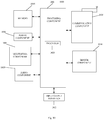
- Fig. 10 is a block diagram of a foldable terminal 1000 according to an exemplary embodiment.
- the terminal 1000 may be a mobile phone, a computer, a digital broadcast terminal, a messaging device, a gaming console, a tablet, a medical device, exercise equipment, a personal digital assistant, and the like.
- the terminal 1000 may include one or more of the following components: a processing component 1002, a memory 1004, a power component 1006, a multimedia component 1008, an audio component 1010, an input/output (I/O) interface 1012, a sensor component 1014, and a communication component 1016.
- the processing component 1002 typically controls overall operations of the terminal 1000, such as the operations associated with display, telephone calls, data communications, camera operations, and recording operations.
- the processing component 1002 may include one or more processors 1020 to execute instructions.
- the processing component 1002 may include one or more modules which facilitate the interaction between the processing component 1002 and other components.
- the processing component 1002 may include a multimedia module to facilitate the interaction between the multimedia component 1008 and the processing component 1002.
- the memory 1004 is configured to store various types of data to support the operation of the terminal 1000. Examples of such data include instructions for any applications or methods operated on the terminal 1000, contact data, phonebook data, messages, pictures, video, etc.
- the memory 1004 may be implemented using any type of volatile or non-volatile memory devices, or a combination thereof, such as a static random access memory (SRAM), an electrically erasable programmable read-only memory (EEPROM), an erasable programmable read-only memory (EPROM), a programmable read-only memory (PROM), a read-only memory (ROM), a magnetic memory, a flash memory, a magnetic or optical disk.
- SRAM static random access memory
- EEPROM electrically erasable programmable read-only memory
- EPROM erasable programmable read-only memory
- PROM programmable read-only memory
- ROM read-only memory
- magnetic memory a magnetic memory
- flash memory a flash memory
- magnetic or optical disk a magnetic or optical
- the power component 1006 provides power to various components of the terminal 1000.
- the power component 1006 may include a power management system, one or more power sources, and any other components associated with the generation, management, and distribution of power in the terminal 1000.
- the multimedia component 1008 includes a screen providing an output interface between the terminal 1000 and the user.
- the screen may be implemented as a flexible display.
- the screen may include a liquid crystal display (LCD) and a touch panel (TP). If the screen includes the touch panel, the screen may be implemented as a touch screen to receive input signals from the user.
- the touch panel includes one or more touch sensors to sense touches, swipes, and gestures on the touch panel. The touch sensors may not only sense a boundary of a touch or swipe action, but also sense a period of time and a pressure associated with the touch or swipe action.
- the multimedia component 1008 includes a front camera and/or a rear camera.
- the front camera and/or the rear camera may receive an external multimedia datum while the terminal 1000 is in an operation mode, such as a photographing mode or a video mode.
- an operation mode such as a photographing mode or a video mode.
- Each of the front camera and the rear camera may be a fixed optical lens system or have focus and optical zoom capability.
- the audio component 1010 is configured to output and/or input audio signals.
- the audio component 1010 includes a microphone ("MIC") configured to receive an external audio signal when the terminal 1000 is in an operation mode, such as a call mode, a recording mode, and a voice recognition mode.
- the received audio signal may be further stored in the memory 1004 or transmitted via the communication component 1016.
- the audio component 1010 further includes a speaker to output audio signals.
- the I/O interface 1012 provides an interface between the processing component 1002 and peripheral interface modules, such as a keyboard, a click wheel, buttons, and the like.
- the buttons may include, but are not limited to, a home button, a volume button, a starting button, and a locking button.
- the sensor component 1014 includes one or more sensors to provide status assessments of various aspects of the terminal 1000. For instance, the sensor component 1014 may detect an open/closed status of the terminal 1000, relative positioning of components, e.g., the display and the keypad, of the terminal 1000, a change in position of the terminal 1000 or a component of the terminal 1000, a presence or absence of user contact with the terminal 1000, an orientation or an acceleration/deceleration of the terminal 1000, and a change in temperature of the terminal 1000.
- the sensor component 1014 may include a proximity sensor configured to detect the presence of nearby objects without any physical contact.
- the sensor component 1014 may also include a light sensor, such as a CMOS or CCD image sensor, for use in imaging applications.
- the sensor component 1014 may also include an accelerometer sensor, a gyroscope sensor, a magnetic sensor, a pressure sensor, or a temperature sensor.
- the communication component 1016 is configured to facilitate communication, wired or wirelessly, between the terminal 1000 and other devices.
- the terminal 1000 can access a wireless network based on a communication standard, such as WiFi, 2G, or 3G, or a combination thereof.
- the communication component 1016 receives a broadcast signal or broadcast associated information from an external broadcast management system via a broadcast channel.
- the communication component 1016 further includes a near field communication (NFC) module to facilitate short-range communications.
- the NFC module may be implemented based on a radio frequency identification (RFID) technology, an infrared data association (IrDA) technology, an ultra-wideband (UWB) technology, a Bluetooth (BT) technology, and other technologies.
- RFID radio frequency identification
- IrDA infrared data association
- UWB ultra-wideband
- BT Bluetooth
- the terminal 1000 may be implemented with one or more application specific integrated circuits (ASICs), digital signal processors (DSPs), digital signal processing devices (DSPDs), programmable logic devices (PLDs), field programmable gate arrays (FPGAs), controllers, micro-controllers, microprocessors, or other electronic components, for performing the above described methods.
- ASICs application specific integrated circuits
- DSPs digital signal processors
- DSPDs digital signal processing devices
- PLDs programmable logic devices
- FPGAs field programmable gate arrays
- controllers micro-controllers, microprocessors, or other electronic components, for performing the above described methods.
- non-transitory computer-readable storage medium including instructions, such as included in the memory 1004, executable by the processor 1020 in the terminal 1000, for performing the above methods.
- the non-transitory computer-readable storage medium may be a ROM, a RAM, a CD-ROM, a magnetic tape, a floppy disc, an optical data storage device, and the like.
Landscapes
- Engineering & Computer Science (AREA)
- Theoretical Computer Science (AREA)
- Computer Hardware Design (AREA)
- Physics & Mathematics (AREA)
- General Engineering & Computer Science (AREA)
- Human Computer Interaction (AREA)
- General Physics & Mathematics (AREA)
- Signal Processing (AREA)
- Mathematical Physics (AREA)
- Microelectronics & Electronic Packaging (AREA)
- Telephone Set Structure (AREA)
- Casings For Electric Apparatus (AREA)
Abstract
Description
- The present invention relates to the field of computer technology, and more particularly to a foldable terminal.
- The flexible display has a foldable function, which makes the terminal equipped with a flexible display possible to be folded.
- In the related art, a terminal equipped with a flexible display is generally equipped with a mechanical structure such as a rotating shaft, and the folding and unfolding of the terminal is realized by a plurality of moving structures in the rotating shaft. However, jamming fault may be easily caused by the manufacturing tolerance of the moving structures, thereby affecting the success rate of the folding.
- In order to overcome the problem existing in the related art, the present invention provides a foldable terminal.
- According to a first aspect of an embodiment of the present invention, there is provided a foldable terminal, including:
- a main body including a first body, a second body, and a rotating shaft connecting the first body and the second body;
- a flexible display fixed to one side of the main body; and
- at least one set of first magnetic components including a first magnet and a second magnet that are attracted to each other,
- wherein the first magnet is disposed on a side of the first body distal from the rotating shaft, the second a magnet is disposed on a side of the second body distal from the rotating shaft; and when the flexible display is in a folded state, positions of the first magnet and the second magnet in each set of first magnetic components are opposite to each other; and
- when an angle between the first body and the second body is less than an angle threshold, an attraction force between the first magnet and the second magnet controls the flexible display to switch from a half-folded state to the folded state.
- The technical solution provided by the embodiment of the present invention may include the following beneficial effects.
- In the foldable terminal provided by the present invention, the folding of the terminal is realized through the attraction force between the first magnetic components, instead of through the moving structure in the rotating shaft. In this way, it can simplify the design of the rotating shaft, avoid jamming fault caused by the manufacturing tolerance of the moving structure, and improve the success rate of the folding.
- When the angle between the first body and the second body is less than the angle threshold, the attraction force controls the flexible display to be automatically switched from a half-folded state to a folded state, which does not require manual folding by the user in the process. Therefore, the first magnetic components can provide assistance during the folding process of the terminal, and avoid the problem that the user needs to exert force in the whole process when the terminal is folded or unfolded through the mechanical structure such as the rotating shaft, thereby improving the user experience. In all embodiments of the present invention, it is preferred that a half-folded state refers to a state in which the display is not completely folded and not completely open. In particular, the half-folded state may refer to a condition, in which the display is slightly open but very near to the completely closed or folded position. Further, in all embodiments of the present invention the term "proximal" refers to a position which is closer to the rotating shaft than a more distal position, which is further away from the rotating shaft compared to the proximal position.
- It should be understood that both the foregoing general description and the following detailed description are exemplary and explanatory only and are not restrictive of the invention.
- The accompanying drawings, which are incorporated in and constitute a part of this specification, illustrate embodiments consistent with the invention and, together with the description, serve to explain the principles of the invention.
-
Fig. 1 is a schematic structural diagram of a foldable terminal according to an exemplary embodiment. -
Fig. 2 is a schematic structural diagram of a foldable terminal according to an exemplary embodiment. -
Fig. 3 is a schematic structural diagram of a foldable terminal according to an exemplary embodiment. -
Fig. 4 is a schematic structural diagram of a foldable terminal according to an exemplary embodiment. -
Fig. 5 is a schematic structural diagram of a foldable terminal according to an exemplary embodiment. -
Fig. 6 is a schematic structural diagram of a foldable terminal according to an exemplary embodiment. -
Fig. 7 is a schematic structural diagram of a foldable terminal according to an exemplary embodiment. -
Fig. 8 is a schematic structural diagram of a foldable terminal according to an exemplary embodiment. -
Fig. 9 is a schematic structural diagram of a foldable terminal according to an exemplary embodiment. -
Fig. 10 is a block diagram of a foldable terminal according to an exemplary embodiment. - Reference will now be made in detail to exemplary embodiments, examples of which are illustrated in the accompanying drawings. The following description refers to the accompanying drawings in which the same numbers in different drawings represent the same or similar elements unless otherwise represented. The implementations set forth in the following description of exemplary embodiments do not represent all implementations consistent with the invention. Instead, they are merely examples of apparatuses and methods consistent with aspects related to the invention as recited in the appended claims.
-
Fig. 1 is a schematic structural diagram of a foldable terminal 100 according to an exemplary embodiment. As shown inFig. 1 , the terminal 100 may include: - a
main body 110 including afirst body 111, asecond body 112, and a rotatingshaft 113 connecting thefirst body 111 and thesecond body 112; - a
flexible display 120 fixed to one side of themain body 110; and - at least one set of first
magnetic components 130. - The first
magnetic components 130 include afirst magnet 131 and asecond magnet 132 that are attracted to each other, thefirst magnet 131 is disposed on a side of thefirst body 111 distal from the rotatingshaft 113, and thesecond magnet 132 is disposed on a side of thesecond body 112 distal from the rotatingshaft 113. When theflexible display 120 is in a folded state, the positions of thefirst magnet 131 and thesecond magnet 132 in each set of the firstmagnetic components 130 are opposite to each other. - When the angle between the
first body 111 and thesecond body 112 is less than an angle threshold, attraction force between thefirst magnet 131 and thesecond magnet 132 controls theflexible display 120 to be switched from a half-folded state to a folded state. - The half-folded state refers to a state in which the angle between the
first body 111 and thesecond body 112 is greater than 0° and less than 90°; the folded state refers to a complete folded state or a substantially complete folded state. In a complete folded state, the angle between thefirst body 111 and thesecond body 112 is equal to 0°, and in a substantially complete folded state, the angle between thefirst body 111 and thesecond body 112 is substantially equal to 0°, that is, the angle is in a range between 0° and a small angle. - In
Fig. 1 , as an example, two sets of firstmagnetic components 130, with thefirst magnet 131 being a north polarity (N), and thesecond magnet 132 being a south polarity (S) are illustrated. - In sum, in the foldable terminal 100 provided by the present invention, the folding of the terminal is realized through the attraction force between the first magnetic components, instead of through the moving structure in the rotating shaft. In this way, it can simplify the design of the rotating shaft, avoid jamming fault caused by the manufacturing tolerance of the moving structure, and improve the success rate of the folding.
- When the angle between the first body and the second body is less than the angle threshold, the attraction force controls the flexible display to be automatically switched from a half-folded state to a folded state, which does not require manual folding by the user in the process. Therefore, the first magnetic components can provide assistance during the folding process of the terminal, and avoid the problem that the user needs to exert force in the whole process when the terminal is folded through the mechanical structure such as the rotating shaft, thereby improving the user experience.
-
Fig. 2 is a schematic structural diagram of a foldable terminal 200 according to an exemplary embodiment. As shown inFig. 2 , the terminal 200 may include:
amain body 210 including afirst body 211, asecond body 212, and a rotatingshaft 213 connecting thefirst body 211 and thesecond body 212. - The
main body 210 includes components of the terminal 200 other than theflexible display 220. The outer portion of themain body 210 may be covered with a back cover. The internal portion may include a main board, a battery, an antenna, a rear camera, and the like in the terminal 200. Themain body 210 is not limited in this embodiment. - With respect to the rotating
shaft 213, themain body 210 may be divided into two parts, one of which is referred to as thefirst body 211, and the other is referred to as thesecond body 212. The components inside themain body 210 are distributed in thefirst body 211 and thesecond body 212, which is not limited in this embodiment. In order to facilitate differentiation, the body on the left side inFig. 2 is referred to as thefirst body 211, and the body on the right side is referred to as thesecond body 212. - The function of the
rotating shaft 213 in this embodiment is to connect thefirst body 211 and thesecond body 212, and the folding and unfolding of the terminal 200 are not required to be mechanically realized by a plurality of moving structures. Therefore, the design of therotating shaft 213 in this embodiment is relatively simple, and there will be no jamming problems caused by manufacturing tolerance. In this way, it can ensure the success rate of folding and unfolding, and also improve the user experience of folding and unfolding. In addition, since therotating shaft 213 in the embodiment does not need to include a plurality of moving structures, the size of therotating shaft 213 can be reduced, thereby improving the aesthetic appearance of the terminal; and the manufacturing cost of therotating shaft 213 can also be reduced. - The terminal 200 may further include a
flexible display 220 fixed to one side of themain body 210. Specifically, theflexible display 220 is fixed on a side of themain body 210 opposite to the back cover. The entire screen of theflexible display 220 in this embodiment covers one side of themain body 210, and when theflexible display 220 is in an unfolded state, the entire screen presents the display effect. - The terminal 200 may further include at least one set of first
magnetic components 230. The firstmagnetic components 230 include afirst magnet 231 and asecond magnet 232 that are attracted to each other. Thefirst magnet 231 is disposed on a side of thefirst body 211 distal from therotating shaft 213. Thesecond magnet 232 is disposed on a side of thesecond body 212 that is distal from therotating shaft 213. - The
first magnet 231 and thesecond magnet 232 being attracted to each other mean that the magnetic polarity of thefirst magnet 231 on the side proximate to theflexible display 220 is opposite to the magnetic polarity of thesecond magnet 232 on the side proximate to theflexible display 220. In order to simplify the illustration, the magnetic polarity of thefirst magnet 231 refers to the magnetic polarity of thefirst magnet 231 on the side proximate to theflexible display 220, and the magnetic polarity of thesecond magnet 232 refers to the magnetic polarity of thesecond magnet 231 on the side proximate to theflexible display 220. - The magnetic properties of the
first magnet 231 and thesecond magnet 232 are indicated on theflexible display 220 inFig. 2 , and as an example for illustration, the magnetic property of thefirst magnet 231 is north and the magnetic property of thesecond magnet 232 is south inFig. 2 . In the implementation, the magnetic property of thefirst magnet 231 may be set to south, and the magnetic property of thesecond magnet 232 may be set to north, which is not limited in this embodiment. - The distance between the
first magnet 231 and therotating shaft 213 and the distance between thesecond magnet 232 and therotating shaft 213 are equal, such that when theflexible display 220 is in the folded state, the positions of thefirst magnet 231 and thesecond magnets 232 in each set of the firstmagnetic components 230 are opposite to each other. In this way, the attraction force between thefirst magnet 231 and thesecond magnet 232 is parallel to the side edge of the terminal 200, and the terminal 200 can be controlled to be folded along the direction of the side edge, so that the folded terminal has a more square shape and is convenient to be carried. - A magnetic isolation sheet may be disposed between the
first magnet 231 and thesecond magnet 232 in each set of the firstmagnetic components 230. The magnetic isolation sheet is configured to gather the magnetic induction lines, and the more the magnetic induction lines are gathered, the larger the magnetic force will be. Therefore, the attraction force between thefirst magnet 231 and thesecond magnet 232 can be increased. - The magnitude of the magnetic force of the
first magnet 231 and thesecond magnet 232 and the distance between thefirst magnet 231 and therotating shaft 213 relate to the torque of attraction force, as described in detail below. - Since the
first magnet 231 and thesecond magnet 232 are symmetrical with respect to therotating shaft 213, the selection of the position of only thefirst magnet 231 will be described below as an example. After the distance between thefirst magnet 231 and therotating shaft 213 is determined, a straight line may be determined in thefirst body 211 having that distance from therotating shaft 213. Then, thefirst magnet 231 may be disposed on the straight line. When the terminal includes one set of firstmagnetic components 230, thefirst magnet 231 may be disposed at a midpoint of the straight line. When the terminal 200 includes at least two sets of the firstmagnetic components 230, the at least twofirst magnets 231 may be evenly arranged on the straight line. - It should be noted that when the terminal 200 includes at least two sets of first
magnetic components 230, the magnetic properties of all thefirst magnets 231 are the same; or the magnetic properties of some of thefirst magnets 231 may be the same, and the magnetic properties of some of thefirst magnets 231 are different, which is not limited in this embodiment. - The terminal 200 may further include at least one set of second
magnetic components 240. The secondmagnetic components 240 include athird magnet 241 and afourth magnet 242 that are repulsive to each other. Thethird magnet 241 is disposed on a side of thefirst body 211 proximate to therotating shaft 213. Thesecond magnet 242 is disposed on a side of thesecond body 212 proximate to therotating shaft 213. When theflexible display 220 is in the folded state, thethird magnet 241 and thefourth magnet 242 are in an overlapping positional relationship. - The
third magnet 241 and thefourth magnet 242 being repulsive to each other mean that the magnetic polarity of thethird magnet 241 on the side proximate to theflexible display 220 is the same as the magnetic polarity of thefourth magnet 242 on the side proximate to theflexible display 220. In order to simplify the illustration, the magnetic polarity of thethird magnet 241 refers to the magnetic polarity of thethird magnet 241 on the side proximate to theflexible display 220, and the magnetic polarity of thefourth magnet 242 refers to the magnetic polarity of thefourth magnet 242 on the side proximate to theflexible display 220. - The magnetic properties of the
third magnet 241 and thefourth magnet 242 are indicated on theflexible display 220 inFig. 2 , and inFig. 2 , the magnetic property of thethird magnet 241 is the north and the magnetic property of thefourth magnet 242 is the north as an example. In the implementation, the magnetic property of thethird magnet 241 may be set as the south, and the magnetic property of thefourth magnet 242 may be set as the south, which is not limited in this embodiment. - The distance between the
third magnet 241 and therotating shaft 213 and the distance between thefourth magnet 242 and therotating shaft 213 are equal, such that when theflexible display 220 is in the folded state, the positions of thethird magnet 241 and thefourth magnets 242 in each set of the secondmagnetic components 240 are opposite to each other. In this way, the repulsion force between thethird magnet 241 and thefourth magnet 242 is parallel to the side edge of the terminal 200, and the terminal 200 can be controlled to be unfolded along the direction of the side edge, so that the shape of the unfolded terminal is relatively square and convenient for use. - A magnetic isolation sheet may be disposed between the
third magnet 241 and thefourth magnet 242 in each set of the secondmagnetic components 240. The magnetic isolation sheet is configured to gather the magnetic induction lines, and the more the magnetic induction lines are gathered, the larger the magnetic force will be. Therefore, the repulsion force between thethird magnet 241 and thefourth magnet 242 can be increased. - The magnitude of the magnetic force of the
third magnet 241 and thefourth magnet 242 and the distance between thethird magnet 241 and therotating shaft 213 relate to the torque of the repulsion force, as described in detail below. - Since the
third magnet 241 and thefourth magnet 242 are symmetrical with respect to therotating shaft 213, the selection of the position of only thethird magnet 241 will be described below as an example. After the distance between thethird magnet 241 and therotating shaft 213 is determined, a straight line may be determined in thefirst body 211 having that distance from therotating shaft 213, and thethird magnet 241 may be disposed on the straight line. When the terminal includes one set of secondmagnetic components 240, thethird magnet 241 may be disposed at a midpoint of the straight line. When the terminal includes at least two sets of the secondmagnetic components 240, the at least twothird magnets 241 may be evenly arranged on the straight line. - It should be noted that when the terminal 200 includes at least two sets of second
magnetic components 240, the magnetic properties of all thethird magnets 241 are the same; or the magnetic properties of some of thethird magnets 241 may be the same, and the magnetic properties of some of thethird magnets 241 are different, which is not limited in this embodiment. - In this embodiment, when the angle between the
first body 211 and thesecond body 212 is less than the angle threshold, the torque of attraction force between thefirst magnet 231 and thesecond magnet 232 is greater than that of the repulsion force between thethird magnet 241 and thefourth magnet 242, and theflexible display 220 is switched from the half-folded state to the folded state. When the angle between thefirst body 211 and thesecond body 212 is greater than the angle threshold, the torque of attraction force is less than the torque of the repulsion force, and theflexible display 220 is switched from the half-folded state to the unfolded state. - The torque is equal to a product of the force and the force arm, and is used to indicate the effect of the force on the rotation of an object. In this embodiment, for the first
magnetic component 230, the magnetic forces of thefirst magnet 231 and thesecond magnet 232 can be adjusted, which is equivalent to adjusting the magnetic flux to adjust the force of the torque. It is also possible to adjust the distance between thefirst magnet 231 and the rotating shaft, so as to adjust the force arm of the torque, in order to achieving the adjustment of the torque of the attraction force. Similarly, for the secondmagnetic component 240, the magnetic forces of thethird magnet 241 and thefourth magnet 242 can be adjusted, that is, the magnetic flux is adjusted to adjust the force of the torque. It is also possible to adjust the distance between thethird magnet 241 and the rotating shaft, so as to adjust the force arm of the torque, in order to achieving the adjustment of the torque of the repulsion force. - In this embodiment, when the
flexible display 220 is automatically switched from the half-folded state to the folded state, if the torque of attraction force is too large, a sharp collision between thefirst body 211 and thesecond body 212 may occur when they are to be completely folded, thus destroying the terminal. When theflexible display 220 is automatically switched from the half-folded state to the unfolded state, if the torque of the repulsion force is too large, theflexible display 220 may be reversely folded when being unfolded, which may damage theflexible display 220. Therefore, it is necessary to adjust the torque of attraction force and the torque of repulsion force according to empirical values, which can not only protect the terminal but also achieve an excellent user experience in the hand. - It should be noted that when the angle is equal to the angle threshold, the torque of attraction force is equal to the torque of the repulsion force, and the terminal is in a stationary state. It can be seen that the angle threshold is the degree of the angle between the
first body 211 and thesecond body 212 when the torque of the attraction force is balanced with the torque of the repulsion force, and may be an empirical value or an experimental value, which is not limited in this embodiment. - In the present embodiment, the half-folded state refers to a state in which the angle between the
first body 211 and thesecond body 212 is greater than 0° and less than 90°, that is, the state shown inFig. 2 . The folded state refers to a complete folded state and a substantially complete folded state. The angle between thefirst body 211 and thesecond body 212 when being in complete folded state is equal to 0°, that is, the state shown inFig. 3 . The angle between thefirst body 211 and thesecond body 212 when being in a substantially complete folded state is equal to about 0°, that is, the angle is between 0° and a small angle. The unfolded state means that the angle between thefirst body 211 and thesecond body 212 is greater than 90° and less than 180°. - In implementation, when the angle between the
first body 211 and thesecond body 212 is greater than 90° and less than 180°, it is also necessary to switch theflexible display 220 from the unfolded state to the complete unfolded state. The complete unfolded state refers to a state in which the angle between thefirst body 211 and thesecond body 212 is equal to 180°, that is, the state shown inFigs. 4 and5 .Fig. 4 is a side view thereof, andFig. 5 is a plan front view thereof, and the angle between thefirst body 211 and thesecond body 212 inFigs. 4 and5 is 180°. - Optionally, as shown in
Fig. 6 , the terminal further includes at least one set of thirdmagnetic components 250. The thirdmagnetic component 250 includes afifth magnet 251 and asixth magnet 252 that are attracted to each other. Thefifth magnet 251 is disposed in thefirst body 211 on a side opposite to theflexible display 220 and proximate to therotating shaft 213. Thesixth magnet 252 is disposed in thesecond body 212 on a side opposite to theflexible display 220 and proximate to therotating shaft 213. When theflexible display 220 is in the unfolded state, theflexible display 220 can be switched from the unfolded state to the complete folded state under the control of the torque of the attraction force between thefifth magnet 251 and thesixth magnet 252. - In brief, when the
flexible display 220 is disposed at one side of themain body 210, thefifth magnet 251 and thesixth magnet 252 are disposed on the other side of themain body 210, and both of thefifth magnet 251 and thesixth magnet 252 are disposed proximate to therotating shaft 213. - The
fifth magnet 251 and thesixth magnet 252 being attracted to each other mean that the magnetic polarity of thefifth magnet 251 on the side proximate to therotating shaft 213 is opposite to the magnetic polarity of thesixth magnet 252 on the side proximate to therotating shaft 213. In order to simplify the illustration, the magnetic polarity of thefifth magnet 251 refers to the magnetic polarity of thefifth magnet 251 on the side proximate to therotating shaft 213, and the magnetic polarity of thesixth magnet 252 refers to the magnetic polarity of thesixth magnet 252 on the side proximate to therotating shaft 213. - The distance between the
fifth magnet 251 and therotating shaft 213 and the distance between thesixth magnet 252 and therotating shaft 213 are equal, such that when theflexible display 220 is in the complete unfolded state, the positions of thefifth magnet 251 and thesixth magnet 252 in each set of the thirdmagnetic components 250 are opposite to each other. In this way, the attraction force between thefifth magnet 251 and thesixth magnet 252 is parallel to the side edge of the terminal, and the terminal can be controlled to be unfolded along the direction of the side edge, so that the shape of the folded terminal is relatively square and convenient for use. - A magnetic isolation sheet may be disposed between the
fifth magnet 251 and thesixth magnet 252 in each set of the thirdmagnetic components 250. The magnetic isolation sheet is configured to gather the magnetic induction lines, and the more the magnetic induction lines are gathered, the larger the magnetic force will be. Therefore, the attraction force between thefifth magnet 251 and thesixth magnet 252 can be increased. - Referring to
Fig. 6 , it shows a schematic diagram of thefifth magnet 251 and thesixth magnet 252. InFig. 6 , it is illustrated as an example, the magnetic polarity of thefifth magnet 251 is north, and the magnetic polarity of thesixth magnet 252 is south. Since both of themagnet 251 and thesixth magnet 252 are disposed on the back side of theflexible display 220, thefifth magnet 251 and thesixth magnet 252 are indicated by broken lines inFig. 6 . In the implementation, the magnetic properties of thefifth magnet 251 can be set as the south, and the magnetic properties of thesixth magnet 252 can be set as the north, which is not limited in this embodiment. - It should be noted that when the terminal includes at least two sets of the third
magnetic components 250, the magnetic properties of all thefifth magnets 251 are the same; or the magnetic properties of some of thefifth magnets 251 may be the same, and the magnetic properties of some of thefifth magnets 251 are different, which is not limited in this embodiment. - In the related art, the folding and unfolding of the terminal is realized by a mechanical structure such as a rotating shaft. In this process, the terminal stops at a position where the user stops the force, and there is no assistant power, resulting in a poor user experience. In this embodiment, magnetic components are used to assist to fold and unfold the terminal, which can enhance the user experience. In addition, when the folding and unfolding of the terminal is realized by a mechanical structure such as a rotating shaft, the terminal may not be completely folded or completely unfolded due to the problem of the mechanical structure, thereby affecting the user experience. In this embodiment, the first
magnetic component 230 can ensure that the terminal is completely folded, and the thirdmagnetic component 250 can ensure that the terminal is completely unfolded, thereby improving the user experience. - In this embodiment, when the
main body 210 includes onefirst body 211 and onesecond body 212. The sizes of thefirst body 211 and thesecond body 212 may be equal or different, which is not limited in this embodiment. The sizes of thefirst body 211 and thesecond body 212 being equal mean that the length and width of thefirst body 211 are respectively equal to length and width of thesecond body 212. Referring toFig. 3 , at this time, the size of the folded terminal is half of the size of the unfolded terminal. - In this embodiment, when the
main body 210 includes twofirst bodies 211, the twofirst bodies 211 are respectively disposed at two ends of thesecond body 212, as shown inFig. 7 . - In this embodiment, when the
main body 210 includes twofirst bodies 211, the sum of the sizes of the twofirst bodies 211 may be larger than the size of thesecond body 212, or may be smaller than the size of thesecond body 212, or may be equal to the size of thesecond body 212. The sum of the sizes of the twofirst bodies 211 being equal to the size of thesecond body 212 means that each of the widths of the twofirst bodies 211 is equal to the width of thesecond body 212 and the sum of the lengths of the twofirst bodies 211 are equal to the length of thesecond body 212. - When the sum of the sizes of the two
first bodies 211 is equal to the size of thesecond body 212, the sizes of the twofirst bodies 211 may be unequal or equal. When the sizes of the twofirst bodies 211 are equal, the size of each of the twofirst bodies 211 is half of the size of thesecond body 212. Referring toFigs. 8 and9 , the two sets of firstmagnetic components 230 inFig. 8 do not share onesecond magnet 232, and the two sets of firstmagnetic components 230 inFig. 9 share onesecond magnet 232. - In sum, in the foldable terminal provided by the present invention, the folding and unfolding of the terminal is realized respectively through the attraction force between the first magnetic components and the repulsion force between the second magnetic components, instead of through the moving structure in the rotating shaft. In this way, it can simplify the design of the rotating shaft, avoid jamming fault caused by the manufacturing tolerance of the moving structure, and improve the success rate of the folding and unfolding.
- When the angle between the first body and the second body is less than the angle threshold, the torque of attraction force is greater than the torque of the repulsion force, thereby controlling the flexible display to be automatically switched from the half-folded state to the folded state, which does not require manual effort from the user. When the angle between the first body and the second body is greater than the angle threshold, the torque of attraction force is less than the torque of the repulsion force, thereby controlling the flexible display to be automatically switched from the half-folded state to the unfolded state, which does not require manual effort from the user. Therefore, the first magnetic components and the second magnetic components can provide assistance during the folding and unfolding process of the terminal, and avoid the problem that the user needs to exert force in the whole process when the terminal is folded or unfolded through the mechanical structure such as the rotating shaft, thereby improving the user experience.
- The positions of the two magnets in each set of magnetic components are opposite to each other, such that the terminal can be controlled to be folded or unfolded in the direction of the side edges.
- A magnetic isolation sheet is disposed between the two magnets in each set of magnetic components, such that the magnetic induction line can be gathered, thereby increasing the magnetic force between the two magnets.
- By providing at least one set of third magnetic components, the flexible display can be switched from an unfolded state to a complete unfolded state for user convenience.
-
Fig. 10 is a block diagram of a foldable terminal 1000 according to an exemplary embodiment. For example, the terminal 1000 may be a mobile phone, a computer, a digital broadcast terminal, a messaging device, a gaming console, a tablet, a medical device, exercise equipment, a personal digital assistant, and the like. - Referring to
Fig. 10 , the terminal 1000 may include one or more of the following components: aprocessing component 1002, amemory 1004, apower component 1006, amultimedia component 1008, anaudio component 1010, an input/output (I/O)interface 1012, asensor component 1014, and acommunication component 1016. - The
processing component 1002 typically controls overall operations of the terminal 1000, such as the operations associated with display, telephone calls, data communications, camera operations, and recording operations. Theprocessing component 1002 may include one ormore processors 1020 to execute instructions. Moreover, theprocessing component 1002 may include one or more modules which facilitate the interaction between theprocessing component 1002 and other components. For instance, theprocessing component 1002 may include a multimedia module to facilitate the interaction between themultimedia component 1008 and theprocessing component 1002. - The
memory 1004 is configured to store various types of data to support the operation of theterminal 1000. Examples of such data include instructions for any applications or methods operated on the terminal 1000, contact data, phonebook data, messages, pictures, video, etc. Thememory 1004 may be implemented using any type of volatile or non-volatile memory devices, or a combination thereof, such as a static random access memory (SRAM), an electrically erasable programmable read-only memory (EEPROM), an erasable programmable read-only memory (EPROM), a programmable read-only memory (PROM), a read-only memory (ROM), a magnetic memory, a flash memory, a magnetic or optical disk. - The
power component 1006 provides power to various components of theterminal 1000. Thepower component 1006 may include a power management system, one or more power sources, and any other components associated with the generation, management, and distribution of power in theterminal 1000. - The
multimedia component 1008 includes a screen providing an output interface between the terminal 1000 and the user. The screen may be implemented as a flexible display. In some embodiments, the screen may include a liquid crystal display (LCD) and a touch panel (TP). If the screen includes the touch panel, the screen may be implemented as a touch screen to receive input signals from the user. The touch panel includes one or more touch sensors to sense touches, swipes, and gestures on the touch panel. The touch sensors may not only sense a boundary of a touch or swipe action, but also sense a period of time and a pressure associated with the touch or swipe action. In some embodiments, themultimedia component 1008 includes a front camera and/or a rear camera. The front camera and/or the rear camera may receive an external multimedia datum while the terminal 1000 is in an operation mode, such as a photographing mode or a video mode. Each of the front camera and the rear camera may be a fixed optical lens system or have focus and optical zoom capability. - The
audio component 1010 is configured to output and/or input audio signals. For example, theaudio component 1010 includes a microphone ("MIC") configured to receive an external audio signal when the terminal 1000 is in an operation mode, such as a call mode, a recording mode, and a voice recognition mode. The received audio signal may be further stored in thememory 1004 or transmitted via thecommunication component 1016. In some embodiments, theaudio component 1010 further includes a speaker to output audio signals. - The I/
O interface 1012 provides an interface between theprocessing component 1002 and peripheral interface modules, such as a keyboard, a click wheel, buttons, and the like. The buttons may include, but are not limited to, a home button, a volume button, a starting button, and a locking button. - The
sensor component 1014 includes one or more sensors to provide status assessments of various aspects of theterminal 1000. For instance, thesensor component 1014 may detect an open/closed status of the terminal 1000, relative positioning of components, e.g., the display and the keypad, of the terminal 1000, a change in position of the terminal 1000 or a component of the terminal 1000, a presence or absence of user contact with the terminal 1000, an orientation or an acceleration/deceleration of the terminal 1000, and a change in temperature of theterminal 1000. Thesensor component 1014 may include a proximity sensor configured to detect the presence of nearby objects without any physical contact. Thesensor component 1014 may also include a light sensor, such as a CMOS or CCD image sensor, for use in imaging applications. In some embodiments, thesensor component 1014 may also include an accelerometer sensor, a gyroscope sensor, a magnetic sensor, a pressure sensor, or a temperature sensor. - The
communication component 1016 is configured to facilitate communication, wired or wirelessly, between the terminal 1000 and other devices. The terminal 1000 can access a wireless network based on a communication standard, such as WiFi, 2G, or 3G, or a combination thereof. In one exemplary embodiment, thecommunication component 1016 receives a broadcast signal or broadcast associated information from an external broadcast management system via a broadcast channel. In one exemplary embodiment, thecommunication component 1016 further includes a near field communication (NFC) module to facilitate short-range communications. For example, the NFC module may be implemented based on a radio frequency identification (RFID) technology, an infrared data association (IrDA) technology, an ultra-wideband (UWB) technology, a Bluetooth (BT) technology, and other technologies. - In exemplary embodiments, the terminal 1000 may be implemented with one or more application specific integrated circuits (ASICs), digital signal processors (DSPs), digital signal processing devices (DSPDs), programmable logic devices (PLDs), field programmable gate arrays (FPGAs), controllers, micro-controllers, microprocessors, or other electronic components, for performing the above described methods.
- In exemplary embodiments, there is also provided a non-transitory computer-readable storage medium including instructions, such as included in the
memory 1004, executable by theprocessor 1020 in the terminal 1000, for performing the above methods. For example, the non-transitory computer-readable storage medium may be a ROM, a RAM, a CD-ROM, a magnetic tape, a floppy disc, an optical data storage device, and the like. - Other embodiments of the invention will be apparent to those skilled in the art from consideration of the specification and practice of the invention disclosed here. This application is intended to cover any variations, uses, or adaptations of the invention following the general principles thereof and including such departures from the present invention as come within known or customary practice in the art. It is intended that the specification and examples be considered as exemplary only, with a true scope of the invention being indicated by the following claims.
- It will be appreciated that the present invention is not limited to the exact construction that has been described above and illustrated in the accompanying drawings, and that various modifications and changes may be made without departing from the scope thereof. It is intended that the scope of the invention only be limited by the appended claims.
Claims (10)
- A foldable terminal, comprising:a main body (110, 210) comprising a first body (111, 211), a second body (112, 212), and a rotating shaft (113, 213) connecting the first body (111, 211) and the second body (112, 212);a flexible display (120, 220) fixed to one side of the main body (110, 210); andat least one set of first magnetic components (130, 230) comprising a first magnet (131, 231) and a second magnet (132, 232) that are attracted to each other,wherein the first magnet (131, 231) is disposed on a side of the first body (111, 211) distal from the rotating shaft (113, 213), the second magnet (132, 232) is disposed on a side of the second body (112, 212) distal from the rotating shaft (113, 213); and when the flexible display (120, 220) is in a folded state, positions of the first magnet (131, 231) and the second magnet (132, 232) in each set of first magnetic components (130, 230) are opposite to each other; andwhen an angle between the first body (111, 211) and the second body (112, 212) is less than an angle threshold, an attraction force between the first magnet (131, 231) and the second magnet (132, 232) controls the flexible display (120, 220) to switch from a half-folded state to the folded state.
- The terminal according to claim 1, further comprising:at least one set of second magnetic components (240) comprising a third magnet (241) and a fourth magnet (242) that are repulsive to each other,wherein the third magnet (241) is disposed on a side of the first body (211) proximate to the rotating shaft (213), the fourth magnet (242) is disposed on a side of the second body (212) proximate to the rotating shaft (213), and when the flexible display (220) is in the folded state, positions of the third magnet (241) and the forth magnet (242) are in an overlapping positional relationship;when the angle between the first body (211) and the second body (212) is less than the angle threshold, a torque of the attraction force between the first magnet (231) and the second magnet (232) is greater than a torque of a repulsion force between the third magnet (241) and the fourth magnet (242), and the flexible display (220) is switched from the half-folded state to the folded state; andwhen the angle between the first body (211) and the second body (212) is greater than the angle threshold, the torque of the attraction force is less than the torque of the repulsion force, and the flexible display (220) is switched from the half-folded state to the unfolded state.
- The terminal according to claim 1, further comprising at least one set of third magnetic components (250) including a fifth magnet (251) and a sixth magnet (252) that are attracted to each other,
wherein the fifth magnet (251) is disposed on a side of the first body (211) opposite to the flexible display (220) and proximate to the rotating shaft (213), and the sixth magnet (252) is disposed on a side of the second body (212) opposite to the flexible display (220) and proximate to the rotating shaft (213); when the flexible display (220) is in a complete unfolded state, positions of the fifth magnet (251) and the sixth magnet (252) in each set of third magnetic components (230) are opposite to each other; and
when the flexible display (220) is in the unfolded state, the flexible display (220) is switched from the unfolded state to the complete unfolded state under control of a torque of an attraction force between the fifth magnet (251) and the sixth magnet (252). - The terminal according to claim 3, wherein a magnetic isolation sheet is disposed between the fifth magnet (251) and the sixth magnet (252) in each set of the third magnetic components (250), and the magnetic isolation sheet is configured to gather magnetic induction lines.
- The terminal according to claim 1, wherein:a magnetic isolation sheet is disposed between the first magnet (231) and the second magnet (232) in each set of the first magnetic components (230); andthe magnetic isolation sheet is configured to gather magnetic induction lines.
- The terminal according to claim 1, wherein:a magnetic isolation sheet is disposed between the third magnet (241) and the fourth magnet (242) in each set of the second magnetic components (240); andthe magnetic isolation sheet is configured to gather magnetic induction lines.
- The terminal according to any one of claims 1 to 6, wherein when the main body (210) comprises one first body (211) and one second body (212), sizes of the first body (211) and the second body (212) are equal.
- The terminal according to any one of claims 1 to 6, wherein when the main body (210) comprises two first bodies (211), the two first bodies (211) are respectively disposed at both ends of the second body (212).
- The terminal according to claim 8, wherein a sum of sizes of the two first bodies (211) is equal to a size of the second body (212).
- The terminal according to claim 9, wherein each of the two first bodies (211) has a size half of the size of the second body (212).
Applications Claiming Priority (1)
| Application Number | Priority Date | Filing Date | Title |
|---|---|---|---|
| CN201810775832.9A CN110730255A (en) | 2018-07-16 | 2018-07-16 | Foldable terminal |
Publications (1)
| Publication Number | Publication Date |
|---|---|
| EP3598266A1 true EP3598266A1 (en) | 2020-01-22 |
Family
ID=66092204
Family Applications (1)
| Application Number | Title | Priority Date | Filing Date |
|---|---|---|---|
| EP19167338.3A Pending EP3598266A1 (en) | 2018-07-16 | 2019-04-04 | Foldable terminal |
Country Status (7)
| Country | Link |
|---|---|
| US (1) | US10671126B2 (en) |
| EP (1) | EP3598266A1 (en) |
| JP (1) | JP7369035B2 (en) |
| KR (1) | KR102492959B1 (en) |
| CN (1) | CN110730255A (en) |
| RU (1) | RU2728288C1 (en) |
| WO (1) | WO2020015185A1 (en) |
Cited By (1)
| Publication number | Priority date | Publication date | Assignee | Title |
|---|---|---|---|---|
| WO2021231593A1 (en) * | 2020-05-14 | 2021-11-18 | Microsoft Technology Licensing, Llc | Magnetic closure system for a device |
Families Citing this family (26)
| Publication number | Priority date | Publication date | Assignee | Title |
|---|---|---|---|---|
| KR101850818B1 (en) * | 2012-01-03 | 2018-04-23 | 삼성전자주식회사 | Mobile apparatus |
| US11789499B2 (en) * | 2018-12-18 | 2023-10-17 | Intel Corporation | Systems and methods for automatically opening hinged components of electronic devices |
| KR102730100B1 (en) | 2019-02-20 | 2024-11-14 | 삼성전자주식회사 | Pordable device |
| KR102749454B1 (en) * | 2019-05-03 | 2025-01-03 | 삼성전자주식회사 | Foldable electronic device including hidden damper |
| WO2021015781A1 (en) * | 2019-07-25 | 2021-01-28 | Hewlett-Packard Development Company, L. P. | Foldable computing device |
| US11169573B2 (en) * | 2019-12-23 | 2021-11-09 | Microsoft Technology Licensing, Llc | Display positioning assembly |
| CN111459228A (en) * | 2020-03-31 | 2020-07-28 | Oppo广东移动通信有限公司 | Electronic equipment and opening and closing method thereof |
| CN116235128A (en) * | 2020-07-16 | 2023-06-06 | 三星电子株式会社 | Electronic device including magnet array |
| CN114430431A (en) * | 2020-10-29 | 2022-05-03 | 北京小米移动软件有限公司 | Foldable electronic equipment |
| CN113539107B (en) | 2021-07-23 | 2023-09-19 | 上海天马微电子有限公司 | a display device |
| US12363210B2 (en) | 2021-08-10 | 2025-07-15 | Samsung Electronics Co., Ltd | Foldable electronic device |
| KR20230023418A (en) * | 2021-08-10 | 2023-02-17 | 삼성전자주식회사 | Foldable electronic device |
| CN113676577B (en) * | 2021-08-17 | 2024-04-05 | 维沃移动通信有限公司 | Folding mechanism and electronic equipment |
| KR20230032683A (en) * | 2021-08-31 | 2023-03-07 | 삼성전자주식회사 | Foldable electronic device and control method thereof |
| CN116193005A (en) * | 2021-11-29 | 2023-05-30 | 北京小米移动软件有限公司 | Terminal, terminal control method, and storage medium |
| CN114338870B (en) * | 2021-12-21 | 2024-12-17 | 维沃移动通信有限公司 | Electronic equipment and control method thereof |
| CN114464090B (en) * | 2022-01-26 | 2023-02-28 | 武汉华星光电半导体显示技术有限公司 | display device |
| CN114810802B (en) * | 2022-04-21 | 2023-05-23 | 荣耀终端有限公司 | Rotating shaft assembly and foldable device |
| WO2024010341A1 (en) * | 2022-07-04 | 2024-01-11 | 삼성전자 주식회사 | Electronic device comprising magnet assembly |
| CN115695604B (en) * | 2022-09-29 | 2023-08-08 | 荣耀终端有限公司 | Control method, device, electronic device and readable storage medium of folding screen |
| WO2024191122A1 (en) * | 2023-03-14 | 2024-09-19 | 삼성전자 주식회사 | Electronic device comprising hinge apparatus |
| CN120917399A (en) * | 2023-03-28 | 2025-11-07 | 三星电子株式会社 | Foldable electronic device and method of operating the same |
| CN117238213A (en) * | 2023-08-30 | 2023-12-15 | 厦门天马显示科技有限公司 | Display device |
| WO2025095743A1 (en) * | 2023-11-03 | 2025-05-08 | 삼성전자 주식회사 | Multi-foldable electronic device comprising magnet |
| CN120035065A (en) * | 2023-11-22 | 2025-05-23 | 华为技术有限公司 | Shell assembly and folding screen device |
| WO2026054604A1 (en) * | 2024-09-09 | 2026-03-12 | 삼성전자 주식회사 | Foldable electronic device |
Citations (3)
| Publication number | Priority date | Publication date | Assignee | Title |
|---|---|---|---|---|
| CN105491194A (en) * | 2015-12-29 | 2016-04-13 | 广东欧珀移动通信有限公司 | Folding terminal |
| US20160278222A1 (en) * | 2015-03-17 | 2016-09-22 | Samsung Display Co., Ltd. | Display device |
| KR20170069115A (en) * | 2015-12-10 | 2017-06-20 | 엘지전자 주식회사 | Mobile terminal |
Family Cites Families (23)
| Publication number | Priority date | Publication date | Assignee | Title |
|---|---|---|---|---|
| KR100745800B1 (en) * | 2004-04-27 | 2007-08-02 | 엘지전자 주식회사 | Latches for Portable Computers |
| TWI275004B (en) | 2005-08-16 | 2007-03-01 | Asustek Comp Inc | Foldable electronic device |
| US7583500B2 (en) * | 2005-12-13 | 2009-09-01 | Apple Inc. | Electronic device having magnetic latching mechanism |
| KR101162215B1 (en) * | 2006-08-22 | 2012-07-04 | 엘지전자 주식회사 | Mobile phone |
| US7593524B2 (en) * | 2006-11-27 | 2009-09-22 | Nokia Corporation | Hinge arrangement |
| US20080278269A1 (en) * | 2007-05-10 | 2008-11-13 | Ernesto Ramirez | System and Method for an Information Handling System Articulated Magnetic Latch |
| KR20090036191A (en) * | 2007-10-09 | 2009-04-14 | 삼성전자주식회사 | Dual display device and multi display device using the same |
| TWI340618B (en) * | 2007-10-23 | 2011-04-11 | Htc Corp | Electronic device |
| US20100238620A1 (en) * | 2009-03-23 | 2010-09-23 | Ram David Adva Fish | Magnetic Notebooks and Tablets |
| US9338265B2 (en) * | 2011-12-29 | 2016-05-10 | Intel Corporation | Mobile device to operate in tablet mode and phone mode |
| US9064654B2 (en) * | 2012-03-02 | 2015-06-23 | Microsoft Technology Licensing, Llc | Method of manufacturing an input device |
| US8705229B2 (en) * | 2012-04-25 | 2014-04-22 | Hewlett-Packard Development Company, L.P. | Foldable electronic devices including a first and a second magnet |
| US8947874B2 (en) * | 2012-06-08 | 2015-02-03 | Bartley K. Andre | Portable computing device with a housing secured by a magnetic element and related method |
| KR101991940B1 (en) * | 2012-08-08 | 2019-06-24 | 삼성전자주식회사 | Portable electronic apparatus |
| CN103729026B (en) * | 2012-10-16 | 2017-09-01 | 华硕电脑股份有限公司 | protection cap |
| KR101452871B1 (en) | 2013-01-11 | 2014-10-22 | (주) 프렉코 | Foldable Flexible Display Device |
| TWI495987B (en) * | 2013-06-25 | 2015-08-11 | Wistron Corp | Hinge and foldable electronic apparatus |
| KR101727971B1 (en) | 2014-02-21 | 2017-04-18 | 삼성전자주식회사 | Foldable device |
| CN108491107B (en) * | 2015-12-29 | 2021-11-02 | Oppo广东移动通信有限公司 | a mobile terminal |
| KR102398836B1 (en) * | 2016-01-18 | 2022-05-17 | 엘지전자 주식회사 | Mobile terminal |
| CN206547121U (en) * | 2016-03-10 | 2017-10-10 | 吕岳川 | A kind of mobile terminal including flexible display screen |
| CN207184560U (en) * | 2017-09-05 | 2018-04-03 | 广东欧珀移动通信有限公司 | Foldable mobile terminal and its folding mechanism |
| CN208739154U (en) * | 2018-07-16 | 2019-04-12 | 北京小米移动软件有限公司 | foldable terminal |
-
2018
- 2018-07-16 CN CN201810775832.9A patent/CN110730255A/en active Pending
- 2018-09-27 KR KR1020197006830A patent/KR102492959B1/en active Active
- 2018-09-27 JP JP2019547274A patent/JP7369035B2/en active Active
- 2018-09-27 RU RU2019123983A patent/RU2728288C1/en active
- 2018-09-27 WO PCT/CN2018/108034 patent/WO2020015185A1/en not_active Ceased
- 2018-12-21 US US16/229,011 patent/US10671126B2/en active Active
-
2019
- 2019-04-04 EP EP19167338.3A patent/EP3598266A1/en active Pending
Patent Citations (5)
| Publication number | Priority date | Publication date | Assignee | Title |
|---|---|---|---|---|
| US20160278222A1 (en) * | 2015-03-17 | 2016-09-22 | Samsung Display Co., Ltd. | Display device |
| KR20170069115A (en) * | 2015-12-10 | 2017-06-20 | 엘지전자 주식회사 | Mobile terminal |
| EP3396929A1 (en) * | 2015-12-10 | 2018-10-31 | LG Electronics Inc. -1- | Mobile terminal |
| CN105491194A (en) * | 2015-12-29 | 2016-04-13 | 广东欧珀移动通信有限公司 | Folding terminal |
| US20190086966A1 (en) * | 2015-12-29 | 2019-03-21 | Guangdong Oppo Mobile Telecommunications Corp., Ltd. | Foldable terminal |
Cited By (4)
| Publication number | Priority date | Publication date | Assignee | Title |
|---|---|---|---|---|
| WO2021231593A1 (en) * | 2020-05-14 | 2021-11-18 | Microsoft Technology Licensing, Llc | Magnetic closure system for a device |
| NL2025586B1 (en) * | 2020-05-14 | 2021-11-30 | Microsoft Technology Licensing Llc | Magnetic closure system for a device |
| CN115552353A (en) * | 2020-05-14 | 2022-12-30 | 微软技术许可有限责任公司 | Magnetic closure system for equipment |
| US12352076B2 (en) | 2020-05-14 | 2025-07-08 | Microsoft Technology Licensing, Llc | Magnetic closure system for a device |
Also Published As
| Publication number | Publication date |
|---|---|
| JP7369035B2 (en) | 2023-10-25 |
| KR102492959B1 (en) | 2023-01-30 |
| JP2022503244A (en) | 2022-01-12 |
| KR20210027008A (en) | 2021-03-10 |
| US10671126B2 (en) | 2020-06-02 |
| WO2020015185A1 (en) | 2020-01-23 |
| US20200019215A1 (en) | 2020-01-16 |
| CN110730255A (en) | 2020-01-24 |
| RU2728288C1 (en) | 2020-07-29 |
Similar Documents
| Publication | Publication Date | Title |
|---|---|---|
| US10671126B2 (en) | Foldable terminal | |
| EP3671406B1 (en) | Method, apparatus and storage medium for displaying shortcut operation panel | |
| KR101814161B1 (en) | Method and apparatus for controlling electronic device | |
| CN208739154U (en) | foldable terminal | |
| US11199928B2 (en) | Method and apparatus for preventing false touch on edge, and storage medium | |
| US20170064166A1 (en) | Camera-Lens Automatic Pop-Up Assembly | |
| JP2016139947A (en) | Mobile device | |
| CN112068760A (en) | Terminal, display method, display device, and storage medium | |
| CN105513104A (en) | Picture taking method, device and system | |
| CN105516586A (en) | Picture shooting method, device and system | |
| US10705729B2 (en) | Touch control method and apparatus for function key, and storage medium | |
| KR20160034838A (en) | Method and device for displaying contents | |
| CN107529699A (en) | Control method of electronic device and device | |
| CN105278543A (en) | Method and device for increasing flight security, and electronic equipment | |
| CN111880873A (en) | Display processing method and device and computer storage medium | |
| CN106648650A (en) | Method and device for adjusting terminal display status | |
| CN104503657A (en) | Image processing method and device | |
| CN116193005A (en) | Terminal, terminal control method, and storage medium | |
| CN112230827B (en) | Interactive interface switching method and device and electronic equipment | |
| EP3731078B1 (en) | Method and apparatus for responding to gesture operation and storage medium | |
| EP3823302B1 (en) | Terminal device and method for outputting audio | |
| CN106250005A (en) | The control method of application switch and device | |
| US11209665B2 (en) | Application interface display method and apparatus, and storage medium | |
| CN110597443A (en) | Calendar display method, device and medium | |
| CN114430431A (en) | Foldable electronic equipment |
Legal Events
| Date | Code | Title | Description |
|---|---|---|---|
| PUAI | Public reference made under article 153(3) epc to a published international application that has entered the european phase |
Free format text: ORIGINAL CODE: 0009012 |
|
| STAA | Information on the status of an ep patent application or granted ep patent |
Free format text: STATUS: THE APPLICATION HAS BEEN PUBLISHED |
|
| AK | Designated contracting states |
Kind code of ref document: A1 Designated state(s): AL AT BE BG CH CY CZ DE DK EE ES FI FR GB GR HR HU IE IS IT LI LT LU LV MC MK MT NL NO PL PT RO RS SE SI SK SM TR |
|
| AX | Request for extension of the european patent |
Extension state: BA ME |
|
| STAA | Information on the status of an ep patent application or granted ep patent |
Free format text: STATUS: REQUEST FOR EXAMINATION WAS MADE |
|
| 17P | Request for examination filed |
Effective date: 20200715 |
|
| RBV | Designated contracting states (corrected) |
Designated state(s): AL AT BE BG CH CY CZ DE DK EE ES FI FR GB GR HR HU IE IS IT LI LT LU LV MC MK MT NL NO PL PT RO RS SE SI SK SM TR |
|
| STAA | Information on the status of an ep patent application or granted ep patent |
Free format text: STATUS: EXAMINATION IS IN PROGRESS |
|
| 17Q | First examination report despatched |
Effective date: 20211203 |
|
| GRAP | Despatch of communication of intention to grant a patent |
Free format text: ORIGINAL CODE: EPIDOSNIGR1 |
|
| STAA | Information on the status of an ep patent application or granted ep patent |
Free format text: STATUS: GRANT OF PATENT IS INTENDED |
|
| INTG | Intention to grant announced |
Effective date: 20251103 |