EP3598200A1 - Display device for displaying image information conveying depth information - Google Patents
Display device for displaying image information conveying depth information Download PDFInfo
- Publication number
- EP3598200A1 EP3598200A1 EP18184264.2A EP18184264A EP3598200A1 EP 3598200 A1 EP3598200 A1 EP 3598200A1 EP 18184264 A EP18184264 A EP 18184264A EP 3598200 A1 EP3598200 A1 EP 3598200A1
- Authority
- EP
- European Patent Office
- Prior art keywords
- display device
- screen
- hoe
- image information
- light
- Prior art date
- Legal status (The legal status is an assumption and is not a legal conclusion. Google has not performed a legal analysis and makes no representation as to the accuracy of the status listed.)
- Withdrawn
Links
Images


Classifications
-
- G—PHYSICS
- G02—OPTICS
- G02B—OPTICAL ELEMENTS, SYSTEMS OR APPARATUS
- G02B5/00—Optical elements other than lenses
- G02B5/32—Holograms used as optical elements
-
- B—PERFORMING OPERATIONS; TRANSPORTING
- B60—VEHICLES IN GENERAL
- B60K—ARRANGEMENT OR MOUNTING OF PROPULSION UNITS OR OF TRANSMISSIONS IN VEHICLES; ARRANGEMENT OR MOUNTING OF PLURAL DIVERSE PRIME-MOVERS IN VEHICLES; AUXILIARY DRIVES FOR VEHICLES; INSTRUMENTATION OR DASHBOARDS FOR VEHICLES; ARRANGEMENTS IN CONNECTION WITH COOLING, AIR INTAKE, GAS EXHAUST OR FUEL SUPPLY OF PROPULSION UNITS IN VEHICLES
- B60K35/00—Instruments specially adapted for vehicles; Arrangement of instruments in or on vehicles
- B60K35/20—Output arrangements, i.e. from vehicle to user, associated with vehicle functions or specially adapted therefor
- B60K35/21—Output arrangements, i.e. from vehicle to user, associated with vehicle functions or specially adapted therefor using visual output, e.g. blinking lights or matrix displays
- B60K35/22—Display screens
-
- B—PERFORMING OPERATIONS; TRANSPORTING
- B60—VEHICLES IN GENERAL
- B60K—ARRANGEMENT OR MOUNTING OF PROPULSION UNITS OR OF TRANSMISSIONS IN VEHICLES; ARRANGEMENT OR MOUNTING OF PLURAL DIVERSE PRIME-MOVERS IN VEHICLES; AUXILIARY DRIVES FOR VEHICLES; INSTRUMENTATION OR DASHBOARDS FOR VEHICLES; ARRANGEMENTS IN CONNECTION WITH COOLING, AIR INTAKE, GAS EXHAUST OR FUEL SUPPLY OF PROPULSION UNITS IN VEHICLES
- B60K35/00—Instruments specially adapted for vehicles; Arrangement of instruments in or on vehicles
- B60K35/20—Output arrangements, i.e. from vehicle to user, associated with vehicle functions or specially adapted therefor
- B60K35/29—Instruments characterised by the way in which information is handled, e.g. showing information on plural displays or prioritising information according to driving conditions
-
- G—PHYSICS
- G02—OPTICS
- G02B—OPTICAL ELEMENTS, SYSTEMS OR APPARATUS
- G02B27/00—Optical systems or apparatus not provided for by any of the groups G02B1/00 - G02B26/00, G02B30/00
- G02B27/01—Head-up displays
- G02B27/0101—Head-up displays characterised by optical features
- G02B27/0103—Head-up displays characterised by optical features comprising holographic elements
-
- G—PHYSICS
- G02—OPTICS
- G02B—OPTICAL ELEMENTS, SYSTEMS OR APPARATUS
- G02B30/00—Optical systems or apparatus for producing three-dimensional [3D] effects, e.g. stereoscopic images
- G02B30/50—Optical systems or apparatus for producing three-dimensional [3D] effects, e.g. stereoscopic images the image being built up from image elements distributed over a three-dimensional [3D] volume, e.g. voxels
-
- G—PHYSICS
- G02—OPTICS
- G02F—OPTICAL DEVICES OR ARRANGEMENTS FOR THE CONTROL OF LIGHT BY MODIFICATION OF THE OPTICAL PROPERTIES OF THE MEDIA OF THE ELEMENTS INVOLVED THEREIN; NON-LINEAR OPTICS; FREQUENCY-CHANGING OF LIGHT; OPTICAL LOGIC ELEMENTS; OPTICAL ANALOGUE/DIGITAL CONVERTERS
- G02F1/00—Devices or arrangements for the control of the intensity, colour, phase, polarisation or direction of light arriving from an independent light source, e.g. switching, gating or modulating; Non-linear optics
- G02F1/01—Devices or arrangements for the control of the intensity, colour, phase, polarisation or direction of light arriving from an independent light source, e.g. switching, gating or modulating; Non-linear optics for the control of the intensity, phase, polarisation or colour
- G02F1/13—Devices or arrangements for the control of the intensity, colour, phase, polarisation or direction of light arriving from an independent light source, e.g. switching, gating or modulating; Non-linear optics for the control of the intensity, phase, polarisation or colour based on liquid crystals, e.g. single liquid crystal display cells
- G02F1/133—Constructional arrangements; Operation of liquid crystal cells; Circuit arrangements
- G02F1/1333—Constructional arrangements; Manufacturing methods
- G02F1/1335—Structural association of cells with optical devices, e.g. polarisers or reflectors
- G02F1/133502—Antiglare, refractive index matching layers
-
- G—PHYSICS
- G02—OPTICS
- G02F—OPTICAL DEVICES OR ARRANGEMENTS FOR THE CONTROL OF LIGHT BY MODIFICATION OF THE OPTICAL PROPERTIES OF THE MEDIA OF THE ELEMENTS INVOLVED THEREIN; NON-LINEAR OPTICS; FREQUENCY-CHANGING OF LIGHT; OPTICAL LOGIC ELEMENTS; OPTICAL ANALOGUE/DIGITAL CONVERTERS
- G02F1/00—Devices or arrangements for the control of the intensity, colour, phase, polarisation or direction of light arriving from an independent light source, e.g. switching, gating or modulating; Non-linear optics
- G02F1/01—Devices or arrangements for the control of the intensity, colour, phase, polarisation or direction of light arriving from an independent light source, e.g. switching, gating or modulating; Non-linear optics for the control of the intensity, phase, polarisation or colour
- G02F1/13—Devices or arrangements for the control of the intensity, colour, phase, polarisation or direction of light arriving from an independent light source, e.g. switching, gating or modulating; Non-linear optics for the control of the intensity, phase, polarisation or colour based on liquid crystals, e.g. single liquid crystal display cells
- G02F1/133—Constructional arrangements; Operation of liquid crystal cells; Circuit arrangements
- G02F1/1333—Constructional arrangements; Manufacturing methods
- G02F1/1335—Structural association of cells with optical devices, e.g. polarisers or reflectors
- G02F1/133553—Reflecting elements
-
- H—ELECTRICITY
- H10—SEMICONDUCTOR DEVICES; ELECTRIC SOLID-STATE DEVICES NOT OTHERWISE PROVIDED FOR
- H10D—INORGANIC ELECTRIC SEMICONDUCTOR DEVICES
- H10D86/00—Integrated devices formed in or on insulating or conducting substrates, e.g. formed in silicon-on-insulator [SOI] substrates or on stainless steel or glass substrates
- H10D86/40—Integrated devices formed in or on insulating or conducting substrates, e.g. formed in silicon-on-insulator [SOI] substrates or on stainless steel or glass substrates characterised by multiple TFTs
-
- H—ELECTRICITY
- H10—SEMICONDUCTOR DEVICES; ELECTRIC SOLID-STATE DEVICES NOT OTHERWISE PROVIDED FOR
- H10D—INORGANIC ELECTRIC SEMICONDUCTOR DEVICES
- H10D86/00—Integrated devices formed in or on insulating or conducting substrates, e.g. formed in silicon-on-insulator [SOI] substrates or on stainless steel or glass substrates
- H10D86/40—Integrated devices formed in or on insulating or conducting substrates, e.g. formed in silicon-on-insulator [SOI] substrates or on stainless steel or glass substrates characterised by multiple TFTs
- H10D86/60—Integrated devices formed in or on insulating or conducting substrates, e.g. formed in silicon-on-insulator [SOI] substrates or on stainless steel or glass substrates characterised by multiple TFTs wherein the TFTs are in active matrices
-
- B—PERFORMING OPERATIONS; TRANSPORTING
- B60—VEHICLES IN GENERAL
- B60K—ARRANGEMENT OR MOUNTING OF PROPULSION UNITS OR OF TRANSMISSIONS IN VEHICLES; ARRANGEMENT OR MOUNTING OF PLURAL DIVERSE PRIME-MOVERS IN VEHICLES; AUXILIARY DRIVES FOR VEHICLES; INSTRUMENTATION OR DASHBOARDS FOR VEHICLES; ARRANGEMENTS IN CONNECTION WITH COOLING, AIR INTAKE, GAS EXHAUST OR FUEL SUPPLY OF PROPULSION UNITS IN VEHICLES
- B60K2360/00—Indexing scheme associated with groups B60K35/00 or B60K37/00 relating to details of instruments or dashboards
- B60K2360/20—Optical features of instruments
- B60K2360/29—Holographic features
-
- G—PHYSICS
- G02—OPTICS
- G02B—OPTICAL ELEMENTS, SYSTEMS OR APPARATUS
- G02B27/00—Optical systems or apparatus not provided for by any of the groups G02B1/00 - G02B26/00, G02B30/00
- G02B27/01—Head-up displays
- G02B27/0101—Head-up displays characterised by optical features
- G02B2027/0127—Head-up displays characterised by optical features comprising devices increasing the depth of field
Definitions
- One or more embodiments described herein relate to a display device.
- a display device for a vehicle or aircraft the display being configured for displaying images conveying depth information, are presented.
- TFT-LCDs thin-film-transistor liquid-crystal displays
- a flat combiner merges the two images from the two displays to create an image conveying depth information to a user.
- Such a device is described for example in US 2018/157040 A1 .
- An issue of such an arrangement is the relatively large packaging size due to the perpendicular arrangement of the two TFT-LCDs, as well as the combiner which is at about 45° to both displays.
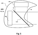
- a conventional display device 100 with two TFT-LCDs is schematically illustrated in Fig. 5 as a cross-sectional view from a side of the display device 100.
- the display device 100 comprises a first TFT-LCD 200 arranged on the left behind a flat combiner 500 at a first distance D1 and a second TFT-LCD 300 arranged on top of the combiner 500 at a second distance D2.
- Two displays 200, 300 which may have different sizes are arranged at an angle of 90 degrees to each other.
- the flat combiner 500 is made of glass and is arranged between the two TFT-LCDs 200, 300 at an angle of 45 degrees.
- An anti-reflection coating is provided on a first surface of the combiner 500 facing the first TFT-LCD 200, and a reflective coating is provided on a second surface of the combiner 500 facing the second TFT-LCD 300.
- One or more embodiments describe an improved display device for displaying images conveying depth information is provided.
- the display device comprises a first display unit for representing first image information on a first screen.
- the first display unit comprises the first screen which is provided with a holographic optical element (HOE) thereon.
- HOE is an optical element such as for example a lens, filter, beam splitter, diffraction grating or mirror that is produced using holographic imaging processes or principles.
- the first display device further comprises a first light source for providing light for illuminating the first screen.
- the first light source serves as a backlight of the first screen.
- a preferred first light source emits light across a broad spectrum of the visible range, such as white light.
- the display device further comprises a second display unit for representing second image information.
- the second display unit comprises a second light source for providing light with a plurality of predetermined discrete wavelengths for creating the second image information.
- the second display unit further comprises a second screen oriented at an acute angle relative to the first screen in order to project the second image information onto the first screen and thereby generate a virtual image corresponding to the second image information behind the first screen.
- the HOE is reflective for the plurality of predetermined discrete wavelengths and transmissive for other wavelengths of the visible spectrum, such that the first image information and the second image information are combined in order to convey depth information.
- the HOE is transmissive for the entire visible spectrum except for the plurality of predetermined discrete wavelengths.
- the display device described herein is thus able to generate images with depth information, wherein a plurality of image planes can be realized by combining the first image information of the first display unit with the second image information of the second display unit.
- One of the image planes corresponds to the first screen.
- the other image planes are virtual image planes appearing behind the first screen.
- the HOE serves to align the second image information projected onto the first display with the first image information in order to combine the first and second image information into a combined image conveying depth information.
- the HOE is a volume HOE which is preferably recorded in a transparent photopolymer film.
- a volume HOE is a HOE with a thickness of the recording material being larger than the light wavelength used for recording.
- visible light has a wavelength between about 390 nm and 700 nm.
- a typical thickness of a volume HOE lies between about 5 ⁇ m and 50 ⁇ m.
- a larger thickness can increase the amount of light reflected by the HOE while decreasing the amount of transmitted light.
- a photopolymer is foreseen as the material for the HOE.
- the holographic structure that is inserted into the HOE can be introduced, for example, by means of a laser.
- a hologram for all of the plurality of predetermined discrete wavelengths is recorded into a single HOE.
- separate HOEs can be recorded for each of the plurality of predetermined discrete wavelengths. Since the HOE is recorded into a thin film, a plurality of separate holograms can be laminated on top of each other.
- the HOE is laminated into or on top of the first screen of the first display unit.
- the HOE can be affixed on one surface of the first screen or optically bonded to it.
- the HOE can be laminated into the first screen.
- the first display unit is a thin-film-transistor liquid-crystal display (TFT-LCD).
- TFT-LCD thin-film-transistor liquid-crystal display
- the first light source comprises light-emitting diodes (LEDs) or organic light-emitting diodes (OLEDs).
- LEDs light-emitting diodes
- OLEDs organic light-emitting diodes
- white light backlighting provided by LEDs or OLEDs can give very good optical contrast and homogenous illumination of the first display.
- the second light source is a laser light source, preferably comprising laser diodes, for example vertical-cavity surface-emitting lasers (VCSELs).
- VCSELs vertical-cavity surface-emitting lasers
- a laser can provide light with a very narrow-bandwidth of only a few nanometers.
- the plurality of predetermined discrete wavelengths may comprise at least red, green, and blue light.
- red, green, and blue light RGB-color scheme
- a broad array of colors can be produced by superimposing a predetermined intensity of each of the three colors.
- the second screen is a diffuser.
- a holographic diffuser may be used as the diffuser.
- a diffuser can be used to concentrate laser light within an angle determined by the field of view, and to reduce laser speckle.
- a real image of the second image information may be generated. This real image is then projected onto the first display unit, thereby generating the virtual image behind the first screen.
- the display device further comprises a control unit for synchronizing the first and second image information.
- a control unit for synchronizing the first and second image information.
- three-dimensional color images can be generated.
- the display device can thus present image information at different image planes, thus conveying depth information. It is thus possible to generate three-dimensional images without the need for glasses to be worn by the user.
- At least two virtual images are generated at different virtual image planes behind the first screen.
- information can be presented to the user in at least three different image planes.
- a first image plane is that of the first (real) image information on the first screen.
- Two more image planes are the at least two virtual image planes behind the first screen.
- information with different levels of priority can be displayed on different image planes.
- depth information can be conveyed in order to more realistically present three-dimensional information. For example, in an instrument cluster for a vehicle or aircraft, situational awareness of the driver or pilot can be improved by presenting information related to the environment of the vehicle or aircraft in different image planes.
- each of the at least two virtual images is generated using at least three predetermined discrete wavelengths, comprising red, green, and blue light.
- each of the virtual images generated at different image planes can be generated in full color using the RGB color scheme.
- a first virtual image is generated using a first wavelength of the plurality of predetermined discrete wavelengths and a second virtual image is generated using a second wavelength of the plurality of predetermined discrete wavelengths different from the first wavelength.
- each predetermined discrete wavelength may be associated with a virtual image plane.
- a first virtual image appearing further distant may be generated using a green laser light source and a second virtual image appearing closer to the user can be generated using a red laser light source.
- the HOE has a flat (planar) mirror element recorded therein.
- a flat mirror is recorded in the HOE, the apparent distance of the generated virtual image from the HOE corresponds to the distance of the object, i.e. of the real image generated on the second screen.
- the HOE has a curved mirror element recorded therein.
- the curved mirror element may be a convex or a concave mirror.
- a curved mirror changes the apparent distance of the virtual image since it either focusses or defocusses the light coming from the second screen.
- the at least two virtual images can be generated by recording at least two mirror functions into at least two HOEs with different sets of RGB laser wavelengths; or into a single HOE in spatial domain, i.e. the central area of the HOE has one mirror function and the outer area has another mirror function.
- different curvatures can be used for the recorded HOEs, such that the virtual images may appear at different distances depending on the wavelength.
- the second light source may use the multiple different sets of RGB laser wavelengths to generate different image planes in full color using the RGB color scheme.
- the second light source may use one set of RGB laser wavelengths, and the image planes may be single color images (for example the first, further distant virtual image is green, and the second, closer virtual image is red).
- an instrument cluster apparatus for a vehicle or an aircraft comprising at least one display device according to one or more embodiments.
- Fig. 1 schematically illustrates an exemplary embodiment of a display device 1 for displaying images conveying depth information to a user.
- a display device 1 may be used for example in an instrument cluster apparatus for a vehicle or an aircraft.
- Fig. 1 is a cross-sectional side view of the display device 1.
- the display device 1 of Fig. 1 comprises a first display unit 2 which may be a thin-film-transistor liquid-crystal display (TFT-LCD) with a first screen 2a onto which a reflective volume holographic optical element (HOE) 2c is laminated. Alternatively, the HOE 2c can be provided inside the first screen 2a.
- the TFT-LCD 2 comprises a first light source 2b which comprises light-emitting diodes (LEDs) or organic light-emitting diodes (OLEDs) emitting white light for illuminating the first screen 2a as backlight.
- first image information can be displayed as a real image.
- White light backlighting using LEDs or OLEDs can provide a very good optical contrast and a homogenous illumination of the first display 1a.
- An advantage of using a TFT-LCD for the first display unit 2 is that a TFT-LCD can provide high quality images with a high resolution. Furthermore, a TFT-LCD can have very good addressability and contrast. In particular, high addressability is important for synchronizing the first image information displayed on the first screen 2a with the second image information provided in the virtual images behind the first screen 2a.
- the display device 1 further comprises a second display unit 3 comprising a second light source 3b and a second screen 3a.
- second image information is represented as a real image.
- the second screen 3a is oriented in parallel or at an acute angle relative to the first screen 2a in order to project the second image information towards the HOE 2c and thereby generate at least one virtual image V1, V2 behind the first screen 2a, corresponding to the second image information and depending on the optical functions that were recorded in the HOE.
- the second light source 3b provides light with a plurality of predetermined discrete wavelengths for creating the second image information.
- the second light source 3b may be a laser system providing at least one red laser beam, one green laser beam, and one blue laser beam.
- the second light source 3b can thus be an RGB laser system.
- the second screen 3a may be a diffuser.
- a diffuser is used in order to concentrate the laser light of the second image within an angle determined by the Field Of View, and to reduce the laser speckle.
- a real image of the second image information may be generated. This real image is then projected onto the HOE 2c, thereby generating the virtual image V1, V2 behind the first screen 2a.
- FIG. 1 two virtual images V1, V2 are represented by dashed lines with different distances behind the first screen 2a.
- the arrows pointing towards the right indicate the direction in which the combined image information comprising the first and second image information is provided to the user.
- Each of the two virtual images V1, V2 can be generated using at least three predetermined discrete wavelengths, comprising red, green, and blue light.
- each of the virtual images V1, V2 generated at different image planes can be generated in full color using the RGB color scheme.
- the first virtual image V1 may be generated using a first wavelength and the second virtual image V2 may be generated using a second wavelength.
- each predetermined discrete wavelength may be associated with a virtual image plane.
- the first virtual image V1 appearing further away with a larger distance to the first screen 2a may be generated using a green laser beam and the second virtual image V2 appearing closer to the first screen 2a (and therefore also closer to the user) can be generated using a red laser beam.
- a warning presented in red as the second virtual image V2 which appears closer to the user than the first virtual image V1.
- the HOE 2c is a reflective volume HOE acting as a mirror for the plurality of predetermined discrete wavelengths emitted by the second light source 3b and transmissive for all other wavelengths of the visible spectrum, such that the first image information and the second image information are combined in order to convey depth information.
- the HOE 2c laminated to the first screen 2a reflects the light from the second display unit 3 toward the user at an angle such that the first display information and the second display information spatially overlap in order to create an image conveying depth information.
- the first and second image information is displayed in a synchronized manner such that the virtual images generated by the second display unit 3 add depth information to the first image information created by the first display unit 2.
- the resulting three-dimensional image therefore differs from conventional stereoscopic images which rely on providing separate images to the left and right eye of an observer.
- the depth information is created by the fact that the virtual images appear behind the first screen 2a.
- depth information can be added by the distance between the virtual and the real image.
- the first display unit 2 may be a TFT-LCD with a HOE 2c laminated on top of the first screen 2a, such that the first image information represented on the first screen 2a can be seen through the HOE 2c by a user as usual.
- the HOE 2c is illuminated by the second light source 3b using narrow-band light conveying second image information which is reflected by the HOE 2c.
- the second image information generates a virtual image behind the first display unit 2, thus conveying depth information to the user.
- the first display unit 2 and the second display unit 3 are arranged inside a cover 4.
- the display device 1 according to the present embodiment provides a significantly reduced package size.
- the depth information can be much greater, since it does not depend on a difference in distance to a centrally arranged combiner but rather depends on the optical properties of the optical elements recorded in the HOE 2c.
- the HOE 2c which acts as a combiner in this case, can be laminated on top of a flat or curved display, for example by using a Liquid Optically Clear Adhesive process, allowing for easier packaging than the centrally arranged glass combiner according to the prior art.
- the display device 1 further comprises a control unit (not depicted) for synchronizing the first and second image information. By synchronizing the first and second image information, three-dimensional color images can be generated. The display device 1 can thus present image information at different image planes or three-dimensional color images without the need for the user to wear special glasses.
- the first light source 2b may comprise LEDs or OLEDs for providing a homogeneous white backlight for illuminating the first screen 2a.
- Exemplary spectra of white light LEDs and white light OLEDs are illustrated in Fig. 2 .
- the line spectra of a blue laser with a wavelength of about 450 nm, of a green laser with a wavelength of about 530 nm, and a red laser with a wavelength of about 630 nm are illustrated in Fig. 2 .
- the three laser lines shown in Fig. 2 can be that of an RGB laser used for a second light source 3b in a second display unit 3.
- Fig. 3 illustrates a process for recording a reflective volume holographic optical element (HOE) by means of interference from a first laser beam and a second laser beam.
- This process corresponds to methods of creating a hologram using interference between a reference beam and an object beam.
- the first laser beam is the reference beam
- the second laser beam is the object beam, wherein the object is a mirror.
- the mirror is a flat mirror
- a flat mirror is recorded as the optical element in the hologram.
- the mirror reflecting the second beam is a curved mirror
- a curved mirror is recorded as the optical element in the hologram.
- the virtual image distance is equal to the distance of the object reflected by the mirror.
- the virtual image distance can be further than the object distance.
- an optical element such as a flat mirror or a curved mirror can be recorded in a thin photopolymer film with a thickness of about 5 to 50 ⁇ m.
- the HOE is a volume HOE which is preferably recorded in a transparent photopolymer film.
- a volume HOE is a HOE with a thickness of the recording material much higher than the light wavelength used for recording.
- visible light has a wavelength between about 390 nm and 700 nm.
- a typical thickness of a volume HOE lies between about 5 ⁇ m and 50 ⁇ m.
- a larger thickness can increase the amount of light reflected by the HOE while decreasing the amount of transmitted light.
- a photopolymer is foreseen as the material for the HOE.
- the holographic structure that is inserted into the HOE can be introduced, for example, by means of a laser.
- a hologram for all of the plurality of predetermined discrete wavelengths of the second light source 3b can be recorded into a single HOE.
- separate HOEs can be recorded for each of the plurality of predetermined discrete wavelengths. Since the HOE is recorded into a thin film, a plurality of separate holograms can be laminated on top of each other onto the first screen 2a.
- the HOE can have a flat (planar) mirror element recorded therein.
- a flat mirror is recorded in the HOE, the apparent distance of the generated virtual image from the HOE 2c corresponds to the distance of the object, i.e. of the real image generated on the second screen 3a, from the HOE 2c.
- the HOE 2c can have a curved mirror element recorded therein.
- a curved mirror changes the apparent distance of the virtual image since it either focusses or defocusses the light coming from the second screen.
- different curvatures can be used for the recorded HOEs, such that the virtual images may appear at different distances depending on the wavelength as illustrated in Fig. 1 .
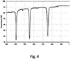
- Fig. 4 illustrates the transmission of light through an exemplary holographic optical element (HOE).
- the exemplary HOE transmits at least about 80% of incident light across a broad frequency spectrum in the visible range and reflects at least about 60% of the laser wavelengths. Narrow-band peaks are visible at about 450 nm, 530 nm, and 630 nm, corresponding to the three laser lines illustrated in the spectrum of Fig. 2 .
- the HOE is configured to reflect light of three predetermined discrete wavelengths in the blue, green, and red spectral range, and to transmit light across the entire visible range except for the three discrete wavelengths.
Landscapes
- Physics & Mathematics (AREA)
- General Physics & Mathematics (AREA)
- Optics & Photonics (AREA)
- Engineering & Computer Science (AREA)
- Chemical & Material Sciences (AREA)
- Nonlinear Science (AREA)
- Transportation (AREA)
- Mechanical Engineering (AREA)
- Combustion & Propulsion (AREA)
- Mathematical Physics (AREA)
- Crystallography & Structural Chemistry (AREA)
- Holo Graphy (AREA)
- Diffracting Gratings Or Hologram Optical Elements (AREA)
Abstract
Description
- One or more embodiments described herein relate to a display device. In particular, one or more embodiments related to a display device for a vehicle or aircraft, the display being configured for displaying images conveying depth information, are presented.
- Current three-dimensional display devices, for example in instrument clusters for vehicles or aircraft, use prism orthogonal display technologies, which employ two separate thin-film-transistor liquid-crystal displays (TFT-LCDs) of equal size arranged at an angle of about 90 degrees to each other. A flat combiner merges the two images from the two displays to create an image conveying depth information to a user. Such a device is described for example in
US 2018/157040 A1 . An issue of such an arrangement is the relatively large packaging size due to the perpendicular arrangement of the two TFT-LCDs, as well as the combiner which is at about 45° to both displays. - For example, in a vehicle such as automobiles and in an aircraft there are often tight dimensional constraints for systems and components. These tight dimensional constraints may result in forgoing systems and components of relatively large packaging sizes, such as when the packaging sizes exceed the dimensional constraints. Alternatively, incorporating systems and components having relatively large packaging sizes may result in forgoing other technologies, such as when the packaging sizes equal the dimensional constraints; thus preventing other systems and components from being incorporated due to a lack of space. As one example, in a vehicle, these issues appear in the space between a dashboard and a firewall.
- A
conventional display device 100 with two TFT-LCDs, like the one mentioned above, is schematically illustrated inFig. 5 as a cross-sectional view from a side of thedisplay device 100. Thedisplay device 100 comprises a first TFT-LCD 200 arranged on the left behind aflat combiner 500 at a first distance D1 and a second TFT-LCD 300 arranged on top of thecombiner 500 at a second distance D2. Twodisplays flat combiner 500 is made of glass and is arranged between the two TFT-LCDs combiner 500 facing the first TFT-LCD 200, and a reflective coating is provided on a second surface of thecombiner 500 facing the second TFT-LCD 300. By reflecting light from the second TFT-LCD 300 and transmitting light from the first TFT-LCD 200 as indicated by the arrows, the images of the two displays 200, 300 are combined into a single image conveying depth information. The difference in distances D2-D1 characterizes the depth of information which can be conveyed by thedisplay device 100. However, only two image planes corresponding to the twodisplays bulky case 400 surrounds the twodisplays combiner 400. - One or more embodiments describe an improved display device for displaying images conveying depth information is provided.
- The display device comprises a first display unit for representing first image information on a first screen. The first display unit comprises the first screen which is provided with a holographic optical element (HOE) thereon. A HOE is an optical element such as for example a lens, filter, beam splitter, diffraction grating or mirror that is produced using holographic imaging processes or principles.
- The first display device further comprises a first light source for providing light for illuminating the first screen. Preferably, the first light source serves as a backlight of the first screen. A preferred first light source emits light across a broad spectrum of the visible range, such as white light.
- The display device further comprises a second display unit for representing second image information. The second display unit comprises a second light source for providing light with a plurality of predetermined discrete wavelengths for creating the second image information. The second display unit further comprises a second screen oriented at an acute angle relative to the first screen in order to project the second image information onto the first screen and thereby generate a virtual image corresponding to the second image information behind the first screen.
- The HOE is reflective for the plurality of predetermined discrete wavelengths and transmissive for other wavelengths of the visible spectrum, such that the first image information and the second image information are combined in order to convey depth information. Preferably, the HOE is transmissive for the entire visible spectrum except for the plurality of predetermined discrete wavelengths.
- The display device described herein is thus able to generate images with depth information, wherein a plurality of image planes can be realized by combining the first image information of the first display unit with the second image information of the second display unit. One of the image planes corresponds to the first screen. The other image planes are virtual image planes appearing behind the first screen. The HOE serves to align the second image information projected onto the first display with the first image information in order to combine the first and second image information into a combined image conveying depth information.
- According to an aspect, the HOE is a volume HOE which is preferably recorded in a transparent photopolymer film. A volume HOE is a HOE with a thickness of the recording material being larger than the light wavelength used for recording. For example, visible light has a wavelength between about 390 nm and 700 nm. A typical thickness of a volume HOE lies between about 5 µm and 50 µm. A larger thickness can increase the amount of light reflected by the HOE while decreasing the amount of transmitted light. At a preferred thickness of about 10 µm a good tradeoff between transmission and reflection of light can be achieved. Preferably, a photopolymer is foreseen as the material for the HOE. The holographic structure that is inserted into the HOE can be introduced, for example, by means of a laser.
- According to an aspect, a hologram for all of the plurality of predetermined discrete wavelengths is recorded into a single HOE. Alternatively, separate HOEs can be recorded for each of the plurality of predetermined discrete wavelengths. Since the HOE is recorded into a thin film, a plurality of separate holograms can be laminated on top of each other.
- According to an aspect, the HOE is laminated into or on top of the first screen of the first display unit. For example, the HOE can be affixed on one surface of the first screen or optically bonded to it. Alternatively, the HOE can be laminated into the first screen.
- According to a further aspect, the first display unit is a thin-film-transistor liquid-crystal display (TFT-LCD). An advantage of using a TFT-LCD is that these displays can provide high-resolution images. Furthermore, a TFT-LCD can have very good addressability and contrast. In particular, high addressability is important for synchronizing the first image information displayed on the first screen with the second image information provided in the virtual images behind the first screen.
- According to an aspect, the first light source comprises light-emitting diodes (LEDs) or organic light-emitting diodes (OLEDs). In particular, white light backlighting provided by LEDs or OLEDs can give very good optical contrast and homogenous illumination of the first display.
- According to an aspect, the second light source is a laser light source, preferably comprising laser diodes, for example vertical-cavity surface-emitting lasers (VCSELs). A laser can provide light with a very narrow-bandwidth of only a few nanometers.
- According to yet another aspect, the plurality of predetermined discrete wavelengths may comprise at least red, green, and blue light. By combining red, green, and blue light (RGB-color scheme), a broad array of colors can be produced by superimposing a predetermined intensity of each of the three colors.
- According to an aspect, the second screen is a diffuser. In particular, a holographic diffuser may be used as the diffuser. A diffuser can be used to concentrate laser light within an angle determined by the field of view, and to reduce laser speckle. On the diffuser, a real image of the second image information may be generated. This real image is then projected onto the first display unit, thereby generating the virtual image behind the first screen.
- According to an aspect, the display device further comprises a control unit for synchronizing the first and second image information. By synchronizing thefirstand second image information, three-dimensional color images can be generated. The display device can thus present image information at different image planes, thus conveying depth information. It is thus possible to generate three-dimensional images without the need for glasses to be worn by the user.
- According to an aspect, at least two virtual images are generated at different virtual image planes behind the first screen. This way, information can be presented to the user in at least three different image planes. A first image plane is that of the first (real) image information on the first screen. Two more image planes are the at least two virtual image planes behind the first screen. For example, information with different levels of priority can be displayed on different image planes. Furthermore, depth information can be conveyed in order to more realistically present three-dimensional information. For example, in an instrument cluster for a vehicle or aircraft, situational awareness of the driver or pilot can be improved by presenting information related to the environment of the vehicle or aircraft in different image planes.
- According to an aspect, each of the at least two virtual images is generated using at least three predetermined discrete wavelengths, comprising red, green, and blue light. Thus, each of the virtual images generated at different image planes can be generated in full color using the RGB color scheme.
- According to a further aspect, a first virtual image is generated using a first wavelength of the plurality of predetermined discrete wavelengths and a second virtual image is generated using a second wavelength of the plurality of predetermined discrete wavelengths different from the first wavelength. In other words, each predetermined discrete wavelength may be associated with a virtual image plane. For example, a first virtual image appearing further distant may be generated using a green laser light source and a second virtual image appearing closer to the user can be generated using a red laser light source. Thereby it is possible to divert more attention of the user to a warning presented in red which also appears closer to the user than the first virtual image.
- According to an aspect, the HOE has a flat (planar) mirror element recorded therein. When a flat mirror is recorded in the HOE, the apparent distance of the generated virtual image from the HOE corresponds to the distance of the object, i.e. of the real image generated on the second screen.
- According to yet another aspect, the HOE has a curved mirror element recorded therein. The curved mirror element may be a convex or a concave mirror. A curved mirror changes the apparent distance of the virtual image since it either focusses or defocusses the light coming from the second screen. The at least two virtual images can be generated by recording at least two mirror functions into at least two HOEs with different sets of RGB laser wavelengths; or into a single HOE in spatial domain, i.e. the central area of the HOE has one mirror function and the outer area has another mirror function. In particular when using separate holograms for different wavelengths, different curvatures can be used for the recorded HOEs, such that the virtual images may appear at different distances depending on the wavelength. The second light source may use the multiple different sets of RGB laser wavelengths to generate different image planes in full color using the RGB color scheme. In another case, the second light source may use one set of RGB laser wavelengths, and the image planes may be single color images (for example the first, further distant virtual image is green, and the second, closer virtual image is red).
- According to yet another aspect, an instrument cluster apparatus for a vehicle or an aircraft is provided comprising at least one display device according to one or more embodiments.
-
-
Fig. 1 schematically illustrates an exemplary embodiment of a display device. -
Fig. 2 schematically illustrates the emission spectra of a light-emitting diode (LED) or an organic light-emitting diode (OLED), each emitting white light, and a laser source emitting three discrete wavelengths. -
Fig. 3 schematically illustrates a process for recording a holographic optical element. -
Fig. 4 illustrates the transmission of light through an exemplary holographic optical element. -
Fig. 5 illustrates a conventional display device according to the prior art. -
Fig. 1 schematically illustrates an exemplary embodiment of adisplay device 1 for displaying images conveying depth information to a user. Such adisplay device 1 may be used for example in an instrument cluster apparatus for a vehicle or an aircraft.Fig. 1 is a cross-sectional side view of thedisplay device 1. - The
display device 1 ofFig. 1 comprises afirst display unit 2 which may be a thin-film-transistor liquid-crystal display (TFT-LCD) with afirst screen 2a onto which a reflective volume holographic optical element (HOE) 2c is laminated. Alternatively, theHOE 2c can be provided inside thefirst screen 2a. The TFT-LCD 2 comprises a firstlight source 2b which comprises light-emitting diodes (LEDs) or organic light-emitting diodes (OLEDs) emitting white light for illuminating thefirst screen 2a as backlight. On thefirst screen 2a, first image information can be displayed as a real image. White light backlighting using LEDs or OLEDs can provide a very good optical contrast and a homogenous illumination of the first display 1a. - An advantage of using a TFT-LCD for the
first display unit 2 is that a TFT-LCD can provide high quality images with a high resolution. Furthermore, a TFT-LCD can have very good addressability and contrast. In particular, high addressability is important for synchronizing the first image information displayed on thefirst screen 2a with the second image information provided in the virtual images behind thefirst screen 2a. - The
display device 1 further comprises asecond display unit 3 comprising a secondlight source 3b and asecond screen 3a. On thesecond screen 3a, second image information is represented as a real image. Thesecond screen 3a is oriented in parallel or at an acute angle relative to thefirst screen 2a in order to project the second image information towards theHOE 2c and thereby generate at least one virtual image V1, V2 behind thefirst screen 2a, corresponding to the second image information and depending on the optical functions that were recorded in the HOE. - The second
light source 3b provides light with a plurality of predetermined discrete wavelengths for creating the second image information. For example, the secondlight source 3b may be a laser system providing at least one red laser beam, one green laser beam, and one blue laser beam. The secondlight source 3b can thus be an RGB laser system. - In the present embodiment, the
second screen 3a may be a diffuser. A diffuser is used in order to concentrate the laser light of the second image within an angle determined by the Field Of View, and to reduce the laser speckle. On thediffuser 3a, a real image of the second image information may be generated. This real image is then projected onto theHOE 2c, thereby generating the virtual image V1, V2 behind thefirst screen 2a. - In
Fig. 1 , two virtual images V1, V2 are represented by dashed lines with different distances behind thefirst screen 2a. The arrows pointing towards the right indicate the direction in which the combined image information comprising the first and second image information is provided to the user. - Each of the two virtual images V1, V2 can be generated using at least three predetermined discrete wavelengths, comprising red, green, and blue light. Thus, each of the virtual images V1, V2 generated at different image planes can be generated in full color using the RGB color scheme.
- Alternatively, the first virtual image V1 may be generated using a first wavelength and the second virtual image V2 may be generated using a second wavelength. In other words, each predetermined discrete wavelength may be associated with a virtual image plane. For example, the first virtual image V1 appearing further away with a larger distance to the
first screen 2a may be generated using a green laser beam and the second virtual image V2 appearing closer to thefirst screen 2a (and therefore also closer to the user) can be generated using a red laser beam. Thereby it is possible to divert more attention of the user to a warning, presented in red as the second virtual image V2 which appears closer to the user than the first virtual image V1. - The
HOE 2c is a reflective volume HOE acting as a mirror for the plurality of predetermined discrete wavelengths emitted by the secondlight source 3b and transmissive for all other wavelengths of the visible spectrum, such that the first image information and the second image information are combined in order to convey depth information. - The
HOE 2c laminated to thefirst screen 2a reflects the light from thesecond display unit 3 toward the user at an angle such that the first display information and the second display information spatially overlap in order to create an image conveying depth information. In particular, the first and second image information is displayed in a synchronized manner such that the virtual images generated by thesecond display unit 3 add depth information to the first image information created by thefirst display unit 2. - The resulting three-dimensional image therefore differs from conventional stereoscopic images which rely on providing separate images to the left and right eye of an observer. In the
present display device 1, the depth information is created by the fact that the virtual images appear behind thefirst screen 2a. When the displayed content corresponding to the first and second image information is synchronized, depth information can be added by the distance between the virtual and the real image. - In principle, the
first display unit 2 may be a TFT-LCD with aHOE 2c laminated on top of thefirst screen 2a, such that the first image information represented on thefirst screen 2a can be seen through theHOE 2c by a user as usual. TheHOE 2c is illuminated by the secondlight source 3b using narrow-band light conveying second image information which is reflected by theHOE 2c. The second image information generates a virtual image behind thefirst display unit 2, thus conveying depth information to the user. - The
first display unit 2 and thesecond display unit 3 are arranged inside acover 4. As becomes apparent when comparingFig. 1 with theconventional display device 100 illustrated inFig. 5 , thedisplay device 1 according to the present embodiment provides a significantly reduced package size. Furthermore, the depth information can be much greater, since it does not depend on a difference in distance to a centrally arranged combiner but rather depends on the optical properties of the optical elements recorded in theHOE 2c. Moreover, theHOE 2c, which acts as a combiner in this case, can be laminated on top of a flat or curved display, for example by using a Liquid Optically Clear Adhesive process, allowing for easier packaging than the centrally arranged glass combiner according to the prior art. - The
display device 1 further comprises a control unit (not depicted) for synchronizing the first and second image information. By synchronizing the first and second image information, three-dimensional color images can be generated. Thedisplay device 1 can thus present image information at different image planes or three-dimensional color images without the need for the user to wear special glasses. - As described above, the first
light source 2b may comprise LEDs or OLEDs for providing a homogeneous white backlight for illuminating thefirst screen 2a. Exemplary spectra of white light LEDs and white light OLEDs are illustrated inFig. 2 . For comparison, the line spectra of a blue laser with a wavelength of about 450 nm, of a green laser with a wavelength of about 530 nm, and a red laser with a wavelength of about 630 nm are illustrated inFig. 2 . The three laser lines shown inFig. 2 can be that of an RGB laser used for a secondlight source 3b in asecond display unit 3. -
Fig. 3 illustrates a process for recording a reflective volume holographic optical element (HOE) by means of interference from a first laser beam and a second laser beam. This process corresponds to methods of creating a hologram using interference between a reference beam and an object beam. Here, the first laser beam is the reference beam and the second laser beam is the object beam, wherein the object is a mirror. If the mirror is a flat mirror, a flat mirror is recorded as the optical element in the hologram. If the mirror reflecting the second beam is a curved mirror, a curved mirror is recorded as the optical element in the hologram. For a flat mirror, the virtual image distance is equal to the distance of the object reflected by the mirror. For a curved mirror, the virtual image distance can be further than the object distance. By means of the process illustrated inFig. 3 , an optical element such as a flat mirror or a curved mirror can be recorded in a thin photopolymer film with a thickness of about 5 to 50 µm. - According to an aspect, the HOE is a volume HOE which is preferably recorded in a transparent photopolymer film. A volume HOE is a HOE with a thickness of the recording material much higher than the light wavelength used for recording. For example, visible light has a wavelength between about 390 nm and 700 nm. A typical thickness of a volume HOE lies between about 5 µm and 50 µm. A larger thickness can increase the amount of light reflected by the HOE while decreasing the amount of transmitted light. At a preferred thickness of about 10 to 20 µm a good tradeoff between transmission and reflection of light can be achieved. Preferably, a photopolymer is foreseen as the material for the HOE. The holographic structure that is inserted into the HOE can be introduced, for example, by means of a laser.
- By means of the illustrated process a hologram for all of the plurality of predetermined discrete wavelengths of the second
light source 3b can be recorded into a single HOE. Alternatively, separate HOEs can be recorded for each of the plurality of predetermined discrete wavelengths. Since the HOE is recorded into a thin film, a plurality of separate holograms can be laminated on top of each other onto thefirst screen 2a. - For example, the HOE can have a flat (planar) mirror element recorded therein. When a flat mirror is recorded in the HOE, the apparent distance of the generated virtual image from the
HOE 2c corresponds to the distance of the object, i.e. of the real image generated on thesecond screen 3a, from theHOE 2c. - Alternatively, the
HOE 2c can have a curved mirror element recorded therein. A curved mirror changes the apparent distance of the virtual image since it either focusses or defocusses the light coming from the second screen. In particular when using separate holograms for different wavelengths, different curvatures can be used for the recorded HOEs, such that the virtual images may appear at different distances depending on the wavelength as illustrated inFig. 1 . -
Fig. 4 illustrates the transmission of light through an exemplary holographic optical element (HOE). As can be seenFig. 4 , the exemplary HOE transmits at least about 80% of incident light across a broad frequency spectrum in the visible range and reflects at least about 60% of the laser wavelengths. Narrow-band peaks are visible at about 450 nm, 530 nm, and 630 nm, corresponding to the three laser lines illustrated in the spectrum ofFig. 2 . In other words, the HOE is configured to reflect light of three predetermined discrete wavelengths in the blue, green, and red spectral range, and to transmit light across the entire visible range except for the three discrete wavelengths. - The features described in the above description, claims and figures can be relevant to the invention in any combination. Their reference numerals in the claims have merely been introduced to facilitate reading of the claims. They are by no means meant to be limiting.
- Throughout this specification various indications have been given as to embodiments of the invention. However, it should be understood that the invention is not limited to any one of these. It is therefore intended that the foregoing detailed description be regarded as illustrative rather than limiting. It is, thus, understood that various changes may be made without departing from the spirit and scope of the invention. Additionally, the features of various implementing embodiments may be combined to form further embodiments of the invention.
-
- 1
- display device
- 2
- first display unit (TFT-LCD)
- 2a
- first screen
- 2b
- first light source (LED or OLED)
- 2c
- holographic optical element (HOE)
- 3
- second display unit
- 3a
- second screen (diffuser)
- 3b
- second light source (RGB laser)
- 4
- case
- V1
- first virtual image
- V2
- second virtual image
Claims (15)
- Display device (1) for displaying images conveying depth information comprising:a first display unit (2) for representing first image information on a first screen (2a), the first display unit (2) comprising:- the first screen (2a) comprising a holographic optical element, HOE, (2c) provided thereon; and- a first light source (2b) for providing light for illuminating the first screen (2a);a second display unit (3) for representing second image information, the second display unit (3) comprising:- a second light source (3b) for providing light with a plurality of predetermined discrete wavelengths for creating the second image information; and- a second screen (3a) provided in parallel or oriented at an angle relative to the first screen (2a) in order to project the second image information onto the first screen (2a) and thereby generate a virtual image corresponding to the second image information behind the first screen (2a),wherein the HOE (2c) is reflective for the plurality of predetermined discrete wavelengths and transmissive for other wavelengths of the visible spectrum, such that the first image information and the second image information are combined in order to convey depth information.
- Display device (1) according to claim 1, wherein the HOE (2c) is a volume HOE recorded in a transparent photopolymer film.
- Display device (1) according to claim 1 or 2, wherein the HOE (2c) is laminated on or into the first screen (2a) of the first display unit (2).
- Display device (1) according to at least one of the preceding claims, wherein the first display unit (2) is a thin-film-transistor liquid-crystal display (TFT-LCD).
- Display device (1) according to at least one of the preceding claims, wherein the first light source (2b) comprises light-emitting diodes (LED) or organic light-emitting diodes (OLED).
- Display device (1) according to at least one of the preceding claims, wherein the second light source (3b) is a laser light source.
- Display device (1) according to at least one of the preceding claims, wherein the plurality of predetermined discrete wavelengths at least comprises red, green, and blue light.
- Display device (1) according to at least one of the preceding claims, wherein the second screen (3a) is a diffuser.
- Display device (1) according to at least one of the preceding claims, further comprising a control unit for synchronizing the first and second image information.
- Display device (1) according to at least one of the preceding claims, wherein one or multiple virtual images (V1, V2) are generated at different virtual image planes behind the first screen (2a).
- Display device (1) according to claim 10, wherein each of the multiple virtual images (V1, V2) is generated using at least three predetermined discrete wavelengths, comprising red, green, and blue light.
- Display device (1) according to claim 10, wherein a first virtual image (V1) is generated using a first wavelength (λ1) of the plurality of predetermined discrete wavelengths and a second virtual image (V2) is generated using a second wavelength (λ2) of the plurality of predetermined discrete wavelengths different from the first wavelength (λ1).
- Display device (1) according to at least one of the preceding claims, wherein the HOE (2c) has a flat mirror element recorded therein.
- Display device (1) according to at any one of claims 1 to 12, wherein the HOE (2c) has a curved mirror element recorded therein.
- Instrument cluster apparatus for a vehicle or an aircraft comprising at least one display device (1) according to at least one of claims 1 to 14.
Priority Applications (2)
| Application Number | Priority Date | Filing Date | Title |
|---|---|---|---|
| EP18184264.2A EP3598200A1 (en) | 2018-07-18 | 2018-07-18 | Display device for displaying image information conveying depth information |
| US16/515,701 US11448810B2 (en) | 2018-07-18 | 2019-07-18 | Display device for displaying image information conveying depth information |
Applications Claiming Priority (1)
| Application Number | Priority Date | Filing Date | Title |
|---|---|---|---|
| EP18184264.2A EP3598200A1 (en) | 2018-07-18 | 2018-07-18 | Display device for displaying image information conveying depth information |
Publications (1)
| Publication Number | Publication Date |
|---|---|
| EP3598200A1 true EP3598200A1 (en) | 2020-01-22 |
Family
ID=63142914
Family Applications (1)
| Application Number | Title | Priority Date | Filing Date |
|---|---|---|---|
| EP18184264.2A Withdrawn EP3598200A1 (en) | 2018-07-18 | 2018-07-18 | Display device for displaying image information conveying depth information |
Country Status (2)
| Country | Link |
|---|---|
| US (1) | US11448810B2 (en) |
| EP (1) | EP3598200A1 (en) |
Citations (9)
| Publication number | Priority date | Publication date | Assignee | Title |
|---|---|---|---|---|
| WO1979000308A1 (en) * | 1977-11-21 | 1979-06-14 | D Ricks | Three dimensional television system |
| JPH10293264A (en) * | 1997-04-18 | 1998-11-04 | Matsushita Electric Ind Co Ltd | Head-up display device |
| FR2815142A1 (en) * | 2000-10-11 | 2002-04-12 | Bosch Gmbh Robert | DEVICE FOR DISPLAYING INFORMATION IN A VEHICLE |
| US20040066547A1 (en) * | 2002-10-04 | 2004-04-08 | William Parker | Full color holographic image combiner system |
| WO2016081890A1 (en) * | 2014-11-20 | 2016-05-26 | Intel Corporation | Adjustable focal plane optical system |
| US20170052369A1 (en) * | 2014-04-30 | 2017-02-23 | Sharp Kabushiki Kaisha | Reflective projection display device |
| US20170153450A1 (en) * | 2005-11-23 | 2017-06-01 | Fusao Ishii | High contrast projection screen |
| JP2017144924A (en) * | 2016-02-18 | 2017-08-24 | 株式会社デンソー | Display device |
| US20180157040A1 (en) | 2016-12-01 | 2018-06-07 | Alexander van Laack | Display device for a motor vehicle |
Family Cites Families (1)
| Publication number | Priority date | Publication date | Assignee | Title |
|---|---|---|---|---|
| US7656585B1 (en) * | 2008-08-19 | 2010-02-02 | Microvision, Inc. | Embedded relay lens for head-up displays or the like |
-
2018
- 2018-07-18 EP EP18184264.2A patent/EP3598200A1/en not_active Withdrawn
-
2019
- 2019-07-18 US US16/515,701 patent/US11448810B2/en active Active
Patent Citations (9)
| Publication number | Priority date | Publication date | Assignee | Title |
|---|---|---|---|---|
| WO1979000308A1 (en) * | 1977-11-21 | 1979-06-14 | D Ricks | Three dimensional television system |
| JPH10293264A (en) * | 1997-04-18 | 1998-11-04 | Matsushita Electric Ind Co Ltd | Head-up display device |
| FR2815142A1 (en) * | 2000-10-11 | 2002-04-12 | Bosch Gmbh Robert | DEVICE FOR DISPLAYING INFORMATION IN A VEHICLE |
| US20040066547A1 (en) * | 2002-10-04 | 2004-04-08 | William Parker | Full color holographic image combiner system |
| US20170153450A1 (en) * | 2005-11-23 | 2017-06-01 | Fusao Ishii | High contrast projection screen |
| US20170052369A1 (en) * | 2014-04-30 | 2017-02-23 | Sharp Kabushiki Kaisha | Reflective projection display device |
| WO2016081890A1 (en) * | 2014-11-20 | 2016-05-26 | Intel Corporation | Adjustable focal plane optical system |
| JP2017144924A (en) * | 2016-02-18 | 2017-08-24 | 株式会社デンソー | Display device |
| US20180157040A1 (en) | 2016-12-01 | 2018-06-07 | Alexander van Laack | Display device for a motor vehicle |
Also Published As
| Publication number | Publication date |
|---|---|
| US20200025992A1 (en) | 2020-01-23 |
| US11448810B2 (en) | 2022-09-20 |
Similar Documents
| Publication | Publication Date | Title |
|---|---|---|
| US11977227B2 (en) | Methods and devices for data projection | |
| EP2755074B1 (en) | Display device for vehicle | |
| EP3770669B1 (en) | Display apparatus and display method | |
| JP6314518B2 (en) | Image display device and display device | |
| US9804564B2 (en) | Apparatus and method for displaying transmission and reflection holograms | |
| US20100079865A1 (en) | Near-to-eye scanning display with exit-pupil expansion | |
| US20140232651A1 (en) | Cascading optics in optical combiners of head mounted displays | |
| US20180081172A1 (en) | Head-up display apparatus | |
| CN104039578A (en) | Reflective display device | |
| KR20130086956A (en) | Display, in particular head-up display of a vehicle | |
| CN111443489B (en) | Multi-angle multi-content heads-up display system and method | |
| EP2312374A1 (en) | Composite image generation system | |
| KR19980020357A (en) | Color holographic head up display | |
| US10955673B2 (en) | Devices for data superimposition | |
| CN116931263A (en) | Head-up display device, head-up display method and vehicle | |
| JP6450944B2 (en) | Display device | |
| US20200103652A1 (en) | Virtual image display device | |
| US11789271B2 (en) | Display apparatus for providing expanded viewing window | |
| US11061370B2 (en) | Viewing system including a holographic optical device allowing images to be displayed in different planes | |
| Martin et al. | Holographic optical elements and projector design considerations for automotive windshield displays | |
| US11448810B2 (en) | Display device for displaying image information conveying depth information | |
| WO2026001050A1 (en) | Display apparatus, head-up display system and vehicle | |
| US20260079289A1 (en) | Optical film for augmented reality devices | |
| JP2017227681A (en) | Head-up display device | |
| JP2022090496A (en) | Virtual image display device and cold mirror |
Legal Events
| Date | Code | Title | Description |
|---|---|---|---|
| PUAI | Public reference made under article 153(3) epc to a published international application that has entered the european phase |
Free format text: ORIGINAL CODE: 0009012 |
|
| STAA | Information on the status of an ep patent application or granted ep patent |
Free format text: STATUS: REQUEST FOR EXAMINATION WAS MADE |
|
| 17P | Request for examination filed |
Effective date: 20191211 |
|
| AK | Designated contracting states |
Kind code of ref document: A1 Designated state(s): AL AT BE BG CH CY CZ DE DK EE ES FI FR GB GR HR HU IE IS IT LI LT LU LV MC MK MT NL NO PL PT RO RS SE SI SK SM TR |
|
| AX | Request for extension of the european patent |
Extension state: BA ME |
|
| STAA | Information on the status of an ep patent application or granted ep patent |
Free format text: STATUS: EXAMINATION IS IN PROGRESS |
|
| 17Q | First examination report despatched |
Effective date: 20200511 |
|
| STAA | Information on the status of an ep patent application or granted ep patent |
Free format text: STATUS: THE APPLICATION HAS BEEN WITHDRAWN |
|
| 18W | Application withdrawn |
Effective date: 20200827 |