EP3598189A1 - Duplex clip assembly for fiber optic connectors - Google Patents
Duplex clip assembly for fiber optic connectors Download PDFInfo
- Publication number
- EP3598189A1 EP3598189A1 EP19195746.3A EP19195746A EP3598189A1 EP 3598189 A1 EP3598189 A1 EP 3598189A1 EP 19195746 A EP19195746 A EP 19195746A EP 3598189 A1 EP3598189 A1 EP 3598189A1
- Authority
- EP
- European Patent Office
- Prior art keywords
- connectors
- duplex
- boot
- clip body
- clip assembly
- Prior art date
- Legal status (The legal status is an assumption and is not a legal conclusion. Google has not performed a legal analysis and makes no representation as to the accuracy of the status listed.)
- Granted
Links
Images












Classifications
-
- G—PHYSICS
- G02—OPTICS
- G02B—OPTICAL ELEMENTS, SYSTEMS OR APPARATUS
- G02B6/00—Light guides; Structural details of arrangements comprising light guides and other optical elements, e.g. couplings
- G02B6/24—Coupling light guides
- G02B6/36—Mechanical coupling means
- G02B6/38—Mechanical coupling means having fibre to fibre mating means
-
- G—PHYSICS
- G02—OPTICS
- G02B—OPTICAL ELEMENTS, SYSTEMS OR APPARATUS
- G02B6/00—Light guides; Structural details of arrangements comprising light guides and other optical elements, e.g. couplings
- G02B6/24—Coupling light guides
- G02B6/36—Mechanical coupling means
- G02B6/38—Mechanical coupling means having fibre to fibre mating means
- G02B6/3807—Dismountable connectors, i.e. comprising plugs
- G02B6/3873—Connectors using guide surfaces for aligning ferrule ends, e.g. tubes, sleeves, V-grooves, rods, pins, balls
- G02B6/3874—Connectors using guide surfaces for aligning ferrule ends, e.g. tubes, sleeves, V-grooves, rods, pins, balls using tubes, sleeves to align ferrules
- G02B6/3878—Connectors using guide surfaces for aligning ferrule ends, e.g. tubes, sleeves, V-grooves, rods, pins, balls using tubes, sleeves to align ferrules comprising a plurality of ferrules, branching and break-out means
- G02B6/3879—Linking of individual connector plugs to an overconnector, e.g. using clamps, clips, common housings comprising several individual connector plugs
-
- G—PHYSICS
- G02—OPTICS
- G02B—OPTICAL ELEMENTS, SYSTEMS OR APPARATUS
- G02B6/00—Light guides; Structural details of arrangements comprising light guides and other optical elements, e.g. couplings
- G02B6/24—Coupling light guides
- G02B6/36—Mechanical coupling means
- G02B6/38—Mechanical coupling means having fibre to fibre mating means
- G02B6/3807—Dismountable connectors, i.e. comprising plugs
- G02B6/381—Dismountable connectors, i.e. comprising plugs of the ferrule type, e.g. fibre ends embedded in ferrules, connecting a pair of fibres
- G02B6/3825—Dismountable connectors, i.e. comprising plugs of the ferrule type, e.g. fibre ends embedded in ferrules, connecting a pair of fibres with an intermediate part, e.g. adapter, receptacle, linking two plugs
-
- G—PHYSICS
- G02—OPTICS
- G02B—OPTICAL ELEMENTS, SYSTEMS OR APPARATUS
- G02B6/00—Light guides; Structural details of arrangements comprising light guides and other optical elements, e.g. couplings
- G02B6/24—Coupling light guides
- G02B6/36—Mechanical coupling means
- G02B6/38—Mechanical coupling means having fibre to fibre mating means
- G02B6/3807—Dismountable connectors, i.e. comprising plugs
- G02B6/3873—Connectors using guide surfaces for aligning ferrule ends, e.g. tubes, sleeves, V-grooves, rods, pins, balls
- G02B6/3885—Multicore or multichannel optical connectors, i.e. one single ferrule containing more than one fibre, e.g. ribbon type
-
- G—PHYSICS
- G02—OPTICS
- G02B—OPTICAL ELEMENTS, SYSTEMS OR APPARATUS
- G02B6/00—Light guides; Structural details of arrangements comprising light guides and other optical elements, e.g. couplings
- G02B6/24—Coupling light guides
- G02B6/36—Mechanical coupling means
- G02B6/38—Mechanical coupling means having fibre to fibre mating means
- G02B6/3807—Dismountable connectors, i.e. comprising plugs
- G02B6/3887—Anchoring optical cables to connector housings, e.g. strain relief features
- G02B6/38875—Protection from bending or twisting
-
- G—PHYSICS
- G02—OPTICS
- G02B—OPTICAL ELEMENTS, SYSTEMS OR APPARATUS
- G02B6/00—Light guides; Structural details of arrangements comprising light guides and other optical elements, e.g. couplings
- G02B6/24—Coupling light guides
- G02B6/36—Mechanical coupling means
- G02B6/38—Mechanical coupling means having fibre to fibre mating means
- G02B6/3807—Dismountable connectors, i.e. comprising plugs
- G02B6/389—Dismountable connectors, i.e. comprising plugs characterised by the method of fastening connecting plugs and sockets, e.g. screw- or nut-lock, snap-in, bayonet type
- G02B6/3893—Push-pull type, e.g. snap-in, push-on
-
- G—PHYSICS
- G02—OPTICS
- G02B—OPTICAL ELEMENTS, SYSTEMS OR APPARATUS
- G02B6/00—Light guides; Structural details of arrangements comprising light guides and other optical elements, e.g. couplings
- G02B6/24—Coupling light guides
- G02B6/36—Mechanical coupling means
- G02B6/38—Mechanical coupling means having fibre to fibre mating means
- G02B6/3807—Dismountable connectors, i.e. comprising plugs
- G02B6/3898—Tools, e.g. handheld; Tuning wrenches; Jigs used with connectors, e.g. for extracting, removing or inserting in a panel, for engaging or coupling connectors, for assembling or disassembling components within the connector, for applying clips to hold two connectors together or for crimping
Definitions
- the present invention relates generally to fiber optic connectors and more specifically to duplex clip assemblies for LC type connectors.
- signals are often paired together, one for transmission and one for reception.
- it is often desirable to have an assembly that can keep the connectors paired together and arranged in the proper polarity.
- due to the high density of the equipment it is also desirable to be able to remove connectors without having to reach the connector housings in order to depress the connector latches.
- the assembly includes a clip body with a hood.
- the clip body has a central wall, upper tabs and lower tabs configured to loosely retain a pair of LC connectors such as to allow the clip body to move axially relative to the LC connectors.
- the hood is configured to engage a camming surface on the LC connector latches when the clip body is moved axially rearward relative to the LC connector.
- the assembly in a second embodiment, includes a duplex housing and a housing cover.
- the duplex housing retains the LC connectors such as to allow them to rotate.
- the housing cover has a hood protruding from the top configured to engage a camming surface on the LC connector latches.
- Figures 1-7 show a first embodiment of an LC duplex clip assembly 100.
- the assembly includes a pair of LC connectors 101, a clip body 102, and a boot 103.
- the clip body 102 has a set of upper tabs 104 and a set of lower tabs 105 connected by a central wall 106.
- the set of upper tabs 104 is perpendicular to the central wall 106 and parallel to the set of lower tabs 105.
- the upper tabs 104 and lower tabs 105 are configured to loosely retain the LC connectors 101 on either side of the central wall 106 such as to allow the clip body 102 to move axially relative to the LC connectors 101.
- the clip body also has a hood 107.
- the hood 107 protrudes from the top of the clip body 102.
- the hood 107 is configured to engage a camming surface 109 on the LC connector latches 108 when the boot 103 and clip body 102 are moved in an axially rearward direction relative to the LC connectors 101.
- the boot 103 attaches to the clip body 102 and is designed to loosely encircle the cables 110 such as to allow the boot 103 to move axially relative to the cables 110 and LC connectors 101.
- the boot 103 connects to the clip body 102 via engagement features 111, 112 on the clip body 102 and boot 103.
- the boot 103 can be manufactured from an elastomeric material to allow bend radius control while also allowing for adequate rigidity for gripping during connector removal and insertion.
- Figs. 8-12 show a second embodiment of an LC duplex clip assembly 200.
- This embodiment adds a center stiffening member 213 to the boot 203.
- the center stiffening member 213 can help prevent the inner walls of the boot 203 from collapsing on the cables 110 when a compressive force, such as from gripping the boot 203 too tightly, is applied to the boot 203. If the walls of the boot 203 were allowed to collapse onto the cable 110, the friction created between the boot 203 and the cables 110 could restrict the free axial motion of the clip body 202 and boot 203.
- the center stiffening member 213 can be located proximate the end of the boot 203 opposite where the boot 203 connects to the clip body 202 in order to allow the boot 203 to flex for bend radius control.
- the boot 203 can be connected to the clip body 102 via a second type of engagement features 211, 212 on the clip body 202 and boot 203.
- the engagement features 211, 212 shown in Figs. 8-12 allow the boot 203 to be disengaged from the clip body 202 by squeezing the sides of the boot 203 to disengage the engagement features 211, 212 and then pulling the boot away from the clip body 202 (see specifically Figs. 11 and 12 ).
- the simple removal process also allows the connectors 101 to be removed from the clip body 202 without a tool and switched from side-to-side in order to reverse the polarity of the duplex clip assembly 200, if necessary.
- the boot 203 can also have raised grip surfaces 214 and an annular protrusion 215 to aid in gripping the boot 203.
- Figure 13 shows another embodiment of an LC duplex clip assembly 300 with a hood 307 in which a portion of the hood can operate as a manual release lever 316, allowing a user to disengage the LC connector latches 108 from their respective ports by either moving the boot 203 and clip body 302 rearward relative to the connectors 101 or by depressing the manual release lever 316.
- FIGS 14-17 show a fourth embodiment of an LC duplex clip assembly 400.
- This embodiment can be used in instances where two fibers are contained in a single cable, such as dual core jacketed cables.
- the assembly 400 includes a duplex housing 451, a housing cover 452, a crimp sleeve 453, a boot 454 and a pair of LC connectors 101.
- the duplex housing 451 can be formed of two halves 451a, 451b and can have a backbone 455 integral with the housing halves (as shown in Figure 14 ) or can be a separate piece trapped by the housing halves 451a, 451b.
- the duplex housing 451 is configured to retain the LC connectors 101 such as to allow them to rotate relative to the duplex housing 451.
- the optical fibers 456 of the cable 458 are terminated to the connectors 101 and the Kevlar fibers 457 of the cable 458 can be secured to the duplex housing 451 via the crimp sleeve 453.
- the housing cover 452 has a hood 459 protruding from the top and is configured to loosely retain the duplex housing 451 and LC connectors 101 such as to allow the housing cover 452 to move axially relative to the LC connectors 101 and duplex housing 451.
- the housing cover 452 can also have an annular protrusion 464 to assist to aid in gripping the housing cover 452.
- moving the housing cover 452 axially rearward relative to the LC connectors 101 and duplex housing 451 causes the hood 459 of the housing cover 403 to engage a camming surface 109 on the LC connector latches 108, which in turn allows the LC connectors 101 to be disengaged from a port 120.
- the LC duplex assembly 400 can be easily reversed in the field by squeezing the sides of the housing cover 452 to disengage the bottom snap 460, retracting the housing cover 452 from the duplex housing 451 and LC connectors 101, rotating each of the LC connectors 101 180 degrees relative to the duplex housing 451, rotating the housing cover 452 180 degrees relative to the duplex housing 451, and pushing the housing cover 452 forward onto the duplex housing 451.
- Figures 18-21 show a fifth embodiment of an LC duplex assembly 500.
- This embodiment is similar to the fourth embodiment except a portion of the hood 559 of the housing cover 552 can also be used as a manual release lever 561 in order to allow a user to disengage the LC connectors 101 from their respective ports by either moving the housing cover 552 rearward relative to the connectors or by depressing the manual release lever 561.
- the manual release lever 561 can snap into place on the remaining portion of the hood 559.
- Figure 22 shows a sixth embodiment of an LC duplex assembly 600.
- This embodiment has a housing cover 652 that does not have a hood and is not designed to move axially relative to the duplex housing and connectors.
- the housing cover 652, as in other embodiments, can be designed to provide side support and prevent the connectors 101 from rotating.
- FIGS 23-24 show a seventh embodiment of an LC duplex assembly 700. This embodiment is similar to the sixth embodiment, except it has a manual release lever 761 extending from the top of the housing cover 752.
- FIGS. 25-28 show an eighth embodiment of an LC duplex assembly 800.
- This embodiment is also similar to the sixth embodiment except the housing cover 852 has locking assembly 870 similar to the one described in U.S. Patent No. 7,632,125 , which is herein incorporated by reference in its entirety.
- Fig. 29 shows a ninth embodiment of an LC duplex clip assembly 900. This embodiment is similar to the sixth embodiment except the duplex housing 951 does not allow the connectors 101 to rotate relative to the duplex housing 951.
- This embodiment 900 can also be easily reversed in the field by retracting the housing cover 652 from the duplex housing 951, sliding each connector 101 out of the duplex housing 951, rotating each connector 101 180 degrees relative to the duplex housing 951, sliding the LC connectors 101 back into the duplex housing 951, rotating the housing cover 652 180 degrees relative to the duplex housing 951, and sliding the housing cover 652 back onto the duplex housing 951.
Landscapes
- Physics & Mathematics (AREA)
- General Physics & Mathematics (AREA)
- Optics & Photonics (AREA)
- Mechanical Coupling Of Light Guides (AREA)
Abstract
Description
- The present invention relates generally to fiber optic connectors and more specifically to duplex clip assemblies for LC type connectors.
- In fiber optic networks signals are often paired together, one for transmission and one for reception. As a result, it is often desirable to have an assembly that can keep the connectors paired together and arranged in the proper polarity. In addition, due to the high density of the equipment, it is also desirable to be able to remove connectors without having to reach the connector housings in order to depress the connector latches.
- This application describes several embodiments of a duplex clip assembly for use in aiding the insertion and removal of a pair of LC fiber optic connectors. In one embodiment, the assembly includes a clip body with a hood. The clip body has a central wall, upper tabs and lower tabs configured to loosely retain a pair of LC connectors such as to allow the clip body to move axially relative to the LC connectors. The hood is configured to engage a camming surface on the LC connector latches when the clip body is moved axially rearward relative to the LC connector.
- In a second embodiment, the assembly includes a duplex housing and a housing cover. The duplex housing retains the LC connectors such as to allow them to rotate. The housing cover has a hood protruding from the top configured to engage a camming surface on the LC connector latches.
-
-
Figure 1 is a perspective view of a first embodiment of an LC duplex clip assembly. -
Figure 2 is a perspective view of the LC duplex clip assembly ofFigure 1 with the boot detached from the clip body. -
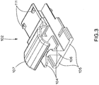
Figure 3 is a perspective view of the clip body of the LC duplex clip assembly ofFigure 1 . -
Figure 4 is a perspective view of the boot of the LC duplex clip assembly ofFigure 1 . -
Figure 5 is a perspective view showing the removal of an LC connector from the clip body of the LC duplex clip assembly ofFigure 1 . -
Figure 6 is a cross-sectional view of the LC duplex clip assembly ofFigure 1 inserted into a port with the LC connector latches engaged with the port. -
Figure 7 is a cross-sectional view of the LC duplex clip assembly ofFigure 1 with the LC connector latches disengaged due to the clip body and boot being moved axially rearward relative to the LC connectors and cables. -
Figure 8 is a perspective view of a second embodiment of a LC duplex clip assembly. -
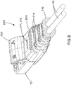
Figure 9 is a perspective view of the LC duplex clip assembly ofFigure 8 with the cables disconnected from the LC connectors to better show the center stiffening member. -
Figure 10 is a side view of the LC duplex clip assembly ofFigure 8 . -
Figure 11 is a cross-sectional view of the LC duplex clip assembly ofFigure 8 taken along line Z-Z ofFigure 10 . -
Figure 12 is a cross-sectional view of the LC duplex clip assembly ofFigure 8 taken along line Z-Z ofFigure 10 with the side of the boot pressed in to disengage the engagement features of the boot from the engagement features of the clip body. -
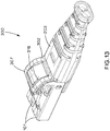
Figure 13 is a perspective view of a third embodiment of an LC duplex clip assembly in which a portion of the hood forms a manual release lever. -
Figure 14 is an exploded perspective view of a fourth embodiment of an LC duplex clip assembly. -
Figure 15 is a bottom perspective view of the LC duplex clip assembly ofFigure 14 . -
Figure 16 is a side view of the LC duplex clip assembly ofFigure 14 . -
Figure 17 is a side view of the LC duplex clip assembly ofFigure 14 with the LC connector latches depressed due to the housing cover being moved axially rearward relative to the LC connectors and duplex housing. -
Figure 18 is a perspective view of a fifth embodiment of an LC duplex clip assembly in which a portion of the hood forms a manual release lever. -
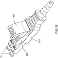
Figure 19 is a perspective view of the LC duplex clip assembly ofFigure 18 with the manual release lever partially removed. -
Figure 20 is a side view of the LC duplex clip assembly ofFigure 18 . -
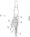
Figure 21 is a cross-sectional view of the LC duplex clip assembly ofFigure 18 . -
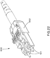
Figure 22 is a perspective view of a sixth embodiment of an LC duplex clip assembly. -
Figure 23 is a perspective view of a seventh embodiment of an LC duplex clip assembly. -
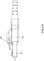
Figure 24 is a side view of the LC duplex clip assembly ofFigure 23 . -
Figure 25 is a perspective view of an eighth embodiment of an LC duplex clip assembly. -
Figure 26 is a bottom perspective view of the LC duplex clip assembly ofFigure 25 . -
Figure 27 is a side view of the LC duplex clip assembly ofFigure 25 . -
Figure 28 is a perspective view of the LC duplex clip assembly ofFigure 25 with a lock-in release tool inserted. -
Figure 29 is an exploded perspective view of a ninth embodiment of an LC duplex clip assembly. -
Figures 1-7 show a first embodiment of an LCduplex clip assembly 100. The assembly includes a pair ofLC connectors 101, aclip body 102, and aboot 103. - As best shown in
Figure 3 , theclip body 102 has a set ofupper tabs 104 and a set oflower tabs 105 connected by acentral wall 106. The set ofupper tabs 104 is perpendicular to thecentral wall 106 and parallel to the set oflower tabs 105. Theupper tabs 104 andlower tabs 105 are configured to loosely retain theLC connectors 101 on either side of thecentral wall 106 such as to allow theclip body 102 to move axially relative to theLC connectors 101. The clip body also has ahood 107. Thehood 107 protrudes from the top of theclip body 102. Thehood 107 is configured to engage acamming surface 109 on theLC connector latches 108 when theboot 103 andclip body 102 are moved in an axially rearward direction relative to theLC connectors 101. - The
boot 103 attaches to theclip body 102 and is designed to loosely encircle thecables 110 such as to allow theboot 103 to move axially relative to thecables 110 andLC connectors 101. In the embodiment shown inFigures 1-7 , theboot 103 connects to theclip body 102 via engagement features 111, 112 on theclip body 102 andboot 103. Theboot 103 can be manufactured from an elastomeric material to allow bend radius control while also allowing for adequate rigidity for gripping during connector removal and insertion. - As best shown is
Figures 6 and7 , moving theboot 103 andclip body 102 axially rearward relative to the LC connectors causes thehood 107 to engage thecamming surfaces 109 of theLC connector latches 108 which in turn disengages theLC connector 101 from theport 120. -
Figs. 8-12 show a second embodiment of an LCduplex clip assembly 200. This embodiment adds acenter stiffening member 213 to theboot 203. Thecenter stiffening member 213 can help prevent the inner walls of theboot 203 from collapsing on thecables 110 when a compressive force, such as from gripping theboot 203 too tightly, is applied to theboot 203. If the walls of theboot 203 were allowed to collapse onto thecable 110, the friction created between theboot 203 and thecables 110 could restrict the free axial motion of theclip body 202 and boot 203. Thecenter stiffening member 213 can be located proximate the end of theboot 203 opposite where theboot 203 connects to theclip body 202 in order to allow theboot 203 to flex for bend radius control. - As shown in
Figs. 8-12 , theboot 203 can be connected to theclip body 102 via a second type of engagement features 211, 212 on theclip body 202 andboot 203. The engagement features 211, 212 shown inFigs. 8-12 , allow theboot 203 to be disengaged from theclip body 202 by squeezing the sides of theboot 203 to disengage theengagement features 211, 212 and then pulling the boot away from the clip body 202 (see specificallyFigs. 11 and12 ). The simple removal process also allows theconnectors 101 to be removed from theclip body 202 without a tool and switched from side-to-side in order to reverse the polarity of theduplex clip assembly 200, if necessary. - The
boot 203 can also have raised grip surfaces 214 and anannular protrusion 215 to aid in gripping theboot 203. -
Figure 13 shows another embodiment of an LCduplex clip assembly 300 with ahood 307 in which a portion of the hood can operate as amanual release lever 316, allowing a user to disengage the LC connector latches 108 from their respective ports by either moving theboot 203 andclip body 302 rearward relative to theconnectors 101 or by depressing themanual release lever 316. -
Figures 14-17 show a fourth embodiment of an LCduplex clip assembly 400. This embodiment can be used in instances where two fibers are contained in a single cable, such as dual core jacketed cables. Theassembly 400 includes aduplex housing 451, ahousing cover 452, acrimp sleeve 453, aboot 454 and a pair ofLC connectors 101. - The
duplex housing 451 can be formed of twohalves backbone 455 integral with the housing halves (as shown inFigure 14 ) or can be a separate piece trapped by thehousing halves duplex housing 451 is configured to retain theLC connectors 101 such as to allow them to rotate relative to theduplex housing 451. Theoptical fibers 456 of thecable 458 are terminated to theconnectors 101 and theKevlar fibers 457 of thecable 458 can be secured to theduplex housing 451 via thecrimp sleeve 453. - The
housing cover 452 has ahood 459 protruding from the top and is configured to loosely retain theduplex housing 451 andLC connectors 101 such as to allow thehousing cover 452 to move axially relative to theLC connectors 101 andduplex housing 451. Thehousing cover 452 can also have anannular protrusion 464 to assist to aid in gripping thehousing cover 452. - As shown best in
Figures 16 and17 , moving thehousing cover 452 axially rearward relative to theLC connectors 101 andduplex housing 451 causes thehood 459 of the housing cover 403 to engage acamming surface 109 on the LC connector latches 108, which in turn allows theLC connectors 101 to be disengaged from aport 120. - If necessary, the
LC duplex assembly 400 can be easily reversed in the field by squeezing the sides of thehousing cover 452 to disengage thebottom snap 460, retracting thehousing cover 452 from theduplex housing 451 andLC connectors 101, rotating each of theLC connectors 101 180 degrees relative to theduplex housing 451, rotating thehousing cover 452 180 degrees relative to theduplex housing 451, and pushing thehousing cover 452 forward onto theduplex housing 451. -
Figures 18-21 show a fifth embodiment of anLC duplex assembly 500. This embodiment is similar to the fourth embodiment except a portion of thehood 559 of thehousing cover 552 can also be used as amanual release lever 561 in order to allow a user to disengage theLC connectors 101 from their respective ports by either moving thehousing cover 552 rearward relative to the connectors or by depressing themanual release lever 561. In one embodiment, themanual release lever 561 can snap into place on the remaining portion of thehood 559. -
Figure 22 shows a sixth embodiment of anLC duplex assembly 600. This embodiment has ahousing cover 652 that does not have a hood and is not designed to move axially relative to the duplex housing and connectors. Thehousing cover 652, as in other embodiments, can be designed to provide side support and prevent theconnectors 101 from rotating. -
Figures 23-24 show a seventh embodiment of anLC duplex assembly 700. This embodiment is similar to the sixth embodiment, except it has amanual release lever 761 extending from the top of thehousing cover 752. -
Figures 25-28 show an eighth embodiment of anLC duplex assembly 800. This embodiment is also similar to the sixth embodiment except thehousing cover 852 has lockingassembly 870 similar to the one described inU.S. Patent No. 7,632,125 , which is herein incorporated by reference in its entirety. -
Fig. 29 shows a ninth embodiment of an LCduplex clip assembly 900. This embodiment is similar to the sixth embodiment except theduplex housing 951 does not allow theconnectors 101 to rotate relative to theduplex housing 951. - This
embodiment 900 can also be easily reversed in the field by retracting thehousing cover 652 from theduplex housing 951, sliding eachconnector 101 out of theduplex housing 951, rotating eachconnector 101 180 degrees relative to theduplex housing 951, sliding theLC connectors 101 back into theduplex housing 951, rotating thehousing cover 652 180 degrees relative to theduplex housing 951, and sliding thehousing cover 652 back onto theduplex housing 951. - While particular embodiments and applications of the present invention have been illustrated and described, it is to be understood that the invention is not limited to the precise construction and compositions disclosed herein and that various modifications, changes, and variations may be apparent from the foregoing without departing from the spirit and scope of the invention as described.
- Also disclosed herein are the following numbered clauses:
- Clause 1. A duplex clip assembly for use in aiding the insertion and removal of a pair of LC fiber optic connectors comprising:
- a clip body, the clip body having a central wall, a set of upper tabs, and a set of lower tabs, the upper tabs being perpendicular to the central wall and parallel to the lower tabs, the central wall, upper tabs, and lower tabs configured to loosely retain a pair of LC connectors and fiber optic cables attached thereto such that the clip body can move axially relative to the LC connectors;
- a hood protruding from a top of the clip body, the hood configured to engage a camming surface on a latch of the LC connectors when the clip body is moved in a rearward, axial direction relative to the LC connectors.
- Clause 2. The duplex clip assembly of clause 1 further comprising a boot attached to the clip body, the boot configured to loosely encircle the fiber optic cables attached to the LC connectors such that the boot is able to move axially in conjunction with the clip body relative to the fiber optic cables and LC connectors.
- Clause 3. The duplex clip assembly of clause 2 wherein the boot has a first end, the first end being attached to the clip body, and a second end opposite the first end, the boot having a center stiffening member proximate the second end.
- Clause 4. The duplex clip assembly of clause 3 wherein the second end of the boot has an annular protrusion.
- Clause 5. The duplex clip assembly of any of clauses 2-4 wherein the boot further comprises raised grip surfaces.
- Clause 6. The duplex clip assembly of any preceding clause wherein at least a portion of the hood also forms a manual release lever that can simultaneously engage the latches on the LC connectors when depressed.
- Clause 7. A duplex clip assembly for use in aiding the insertion and removal of a pair of LC fiber optic connectors comprising:
- a duplex housing, the duplex housing configured to retain a portion of each LC connector;
- a housing cover, the housing cover at least partially enclosing and loosely retaining the duplex housing such as to allow the housing cover to move axially relative to the duplex housing and the LC connectors; and
- a hood, the hood protruding from a top of the housing cover, the hood configured to engage a camming surface on a latch of the LC connectors when the housing cover is moved in a rearward axial direction relative to the LC connectors and duplex housing.
- Clause 8. The duplex clip assembly of clause 7 further comprising a boot configured to partially enclose a dual core fiber optic cable attached to the LC connectors.
- Clause 9. The duplex clip assembly of clause 7 or 8 wherein the housing cover includes an annular protrusion.
- Clause 10. The duplex clip assembly of any of clauses 7 to 9 wherein at least a portion of the hood forms a lever that can simultaneously engage the latches on the LC connectors when depressed.
Claims (6)
- A duplex clip assembly for use in aiding the insertion and removal of a pair of LC fiber optic connectors comprising:a clip body, the clip body having a central wall, a set of upper tabs, and a set of lower tabs, the upper tabs being perpendicular to the central wall and parallel to the lower tabs, the central wall, upper tabs, and lower tabs configured to loosely retain a pair of LC connectors and fiber optic cables attached thereto such that the clip body can move axially relative to the LC connectors;a hood protruding from a top of the clip body, the hood configured to engage a camming surface on a latch of the LC connectors when the clip body is moved in a rearward, axial direction relative to the LC connectors.
- The duplex clip assembly of claim 1 further comprising a boot attached to the clip body, the boot configured to loosely encircle the fiber optic cables attached to the LC connectors such that the boot is able to move axially in conjunction with the clip body relative to the fiber optic cables and LC connectors.
- The duplex clip assembly of claim 2 wherein the boot has a first end, the first end being attached to the clip body, and a second end opposite the first end, the boot having a center stiffening member proximate the second end.
- The duplex clip assembly of claim 3 wherein the second end of the boot has an annular protrusion.
- The duplex clip assembly of any of claims 2 to 4 wherein the boot further comprises raised grip surfaces.
- The duplex clip assembly of any preceding claim wherein at least a portion of the hood also forms a manual release lever that can simultaneously engage the latches on the LC connectors when depressed.
Applications Claiming Priority (3)
| Application Number | Priority Date | Filing Date | Title |
|---|---|---|---|
| US13/153,945 US8764308B2 (en) | 2011-06-06 | 2011-06-06 | Duplex clip assembly for fiber optic connectors |
| PCT/US2012/039590 WO2012170221A1 (en) | 2011-06-06 | 2012-05-25 | Duplex clip assembly for fiber optic connectors |
| EP12726297.0A EP2718757A1 (en) | 2011-06-06 | 2012-05-25 | Duplex clip assembly for fiber optic connectors |
Related Parent Applications (1)
| Application Number | Title | Priority Date | Filing Date |
|---|---|---|---|
| EP12726297.0A Division EP2718757A1 (en) | 2011-06-06 | 2012-05-25 | Duplex clip assembly for fiber optic connectors |
Publications (2)
| Publication Number | Publication Date |
|---|---|
| EP3598189A1 true EP3598189A1 (en) | 2020-01-22 |
| EP3598189B1 EP3598189B1 (en) | 2025-07-09 |
Family
ID=46210443
Family Applications (2)
| Application Number | Title | Priority Date | Filing Date |
|---|---|---|---|
| EP12726297.0A Ceased EP2718757A1 (en) | 2011-06-06 | 2012-05-25 | Duplex clip assembly for fiber optic connectors |
| EP19195746.3A Active EP3598189B1 (en) | 2011-06-06 | 2012-05-25 | Duplex clip assembly for fiber optic connectors |
Family Applications Before (1)
| Application Number | Title | Priority Date | Filing Date |
|---|---|---|---|
| EP12726297.0A Ceased EP2718757A1 (en) | 2011-06-06 | 2012-05-25 | Duplex clip assembly for fiber optic connectors |
Country Status (8)
| Country | Link |
|---|---|
| US (6) | US8764308B2 (en) |
| EP (2) | EP2718757A1 (en) |
| JP (1) | JP6138770B2 (en) |
| KR (1) | KR101904503B1 (en) |
| CN (1) | CN103597390B (en) |
| MX (1) | MX2013013632A (en) |
| TW (1) | TWI504958B (en) |
| WO (1) | WO2012170221A1 (en) |
Families Citing this family (108)
| Publication number | Priority date | Publication date | Assignee | Title |
|---|---|---|---|---|
| ES2402632B1 (en) | 2011-02-08 | 2014-05-14 | Tyco Electronics Raychem Bvba | RELEASE TONGUE FOR AN ELECTRICAL CONNECTOR AND ELECTRICAL CONNECTOR THAT INCLUDES SUCH RELEASE TONGUE |
| ES2395358B1 (en) | 2011-02-08 | 2014-04-25 | Tyco Electronics Corporation | SINGLE ACTION CONNECTOR |
| US8764308B2 (en) | 2011-06-06 | 2014-07-01 | Panduit Corp. | Duplex clip assembly for fiber optic connectors |
| MX347713B (en) * | 2011-10-05 | 2017-05-10 | Senko Advanced Components Inc | Latching connector with remote release. |
| WO2013104125A1 (en) * | 2012-01-12 | 2013-07-18 | 3M Innovative Properties Company | Field mountable duplex optical fiber connector with mechanical splice elements |
| CN103257407B (en) | 2012-02-20 | 2015-11-25 | 泰科电子(上海)有限公司 | Connector and connector assembly |
| CN102565963B (en) * | 2012-02-27 | 2017-04-26 | 深圳日海通讯技术股份有限公司 | High-density optical fiber connector and assembly method thereof |
| WO2014085462A1 (en) | 2012-11-30 | 2014-06-05 | Tyco Electronics Corporation | Fiber optic connector with field installable outer connector housing |
| EP2759859B1 (en) * | 2013-01-29 | 2018-05-16 | Tyco Electronics Nederland B.V. | Guiding support and kit for terminating a transmission cable |
| US9698529B1 (en) * | 2013-02-28 | 2017-07-04 | Amazon Technologies, Inc. | Cable holder for system serviceabilty |
| US9461374B2 (en) * | 2013-03-15 | 2016-10-04 | Molex, Llc | Electrical connector assembly and connecting member thereof |
| US9293862B2 (en) * | 2013-08-26 | 2016-03-22 | Panduit Corp. | Patch cord plug organizer |
| US10048447B2 (en) * | 2013-10-31 | 2018-08-14 | CommScope Connectivity Belgium BVBA | Fiber optic connection system |
| CN104297862B (en) * | 2013-12-13 | 2016-05-18 | 中航光电科技股份有限公司 | Optical fiber connector plug and release clamp part thereof |
| EP3095000B1 (en) | 2014-01-13 | 2021-04-28 | CommScope Telecommunications (Shanghai) Co. Ltd. | Fiber optic connector |
| CN110635304B (en) * | 2014-02-06 | 2022-04-12 | 安费诺富加宜(亚洲)私人有限公司 | Connector assembly |
| CN104849815B (en) | 2014-02-14 | 2017-01-18 | 泰科电子(上海)有限公司 | Optical fiber connector and assembly method therefor |
| CN104849816B (en) | 2014-02-14 | 2017-01-11 | 泰科电子(上海)有限公司 | Optical fiber connector and assembly method therefor |
| JP6247576B2 (en) * | 2014-03-24 | 2017-12-13 | 日本航空電子工業株式会社 | Connector, plug with built-in connector |
| CN105278045B (en) * | 2014-06-20 | 2017-11-24 | 东莞东源光电有限公司 | The joint design of the joints of optical fibre |
| CN105445862B (en) | 2014-07-09 | 2018-01-19 | 泰科电子(上海)有限公司 | The joints of optical fibre and its on-site assembly method |
| WO2016073273A2 (en) * | 2014-11-04 | 2016-05-12 | 3M Innovative Properties Company | Field installed optical fiber connector for jacketed fiber cable and termination method |
| US9658409B2 (en) | 2015-03-03 | 2017-05-23 | Senko Advanced Components, Inc. | Optical fiber connector with changeable polarity |
| GB2538089B (en) * | 2015-05-06 | 2019-06-19 | Fibrefab Ltd | Fibre optic cable assembly |
| WO2017015085A1 (en) | 2015-07-17 | 2017-01-26 | Corning Optical Communications LLC | Systems and methods for tracing cables and cables for such systems and methods |
| US10620385B2 (en) | 2015-11-30 | 2020-04-14 | Commscope Technologies Llc | Fiber optic connector and assembly thereof |
| WO2017106514A1 (en) | 2015-12-16 | 2017-06-22 | Commscope Technologies Llc | Field installed fiber optic connector |
| US9678283B1 (en) * | 2016-01-15 | 2017-06-13 | Senko Advanced Components, Inc. | Fiber optic connector assemblies with adjustable polarity |
| US10158194B2 (en) | 2016-01-15 | 2018-12-18 | Senko Advanced Components, Inc. | Narrow width adapters and connectors with spring loaded remote release |
| USD823812S1 (en) * | 2016-03-02 | 2018-07-24 | Zound Industries International Ab | Data transmission cable |
| USD823261S1 (en) * | 2016-03-02 | 2018-07-17 | Zound Industries International Ab | Data transmission cable |
| USD823260S1 (en) * | 2016-03-02 | 2018-07-17 | Zound Industries International Ab | Data transmission cable |
| US10545298B2 (en) | 2016-12-21 | 2020-01-28 | Corning Research & Development Corporation | Traceable fiber optic cable assembly with illumination structure and tracing optical fibers for carrying light received from a light launch device |
| US10156683B2 (en) | 2016-04-11 | 2018-12-18 | Leviton Manufacturing Co., Inc. | Polarity identification for polarity reversing duplex unibody connectors |
| US9946035B2 (en) * | 2016-04-11 | 2018-04-17 | Leviton Manufacturing Co., Inc. | Fiber optic connector |
| JP2017207594A (en) * | 2016-05-17 | 2017-11-24 | エヌ・ティ・ティ・コミュニケーションズ株式会社 | Optical cable and insertion / extraction method |
| DE202016103178U1 (en) * | 2016-06-16 | 2016-07-07 | Reichle & De-Massari Ag | Connectors |
| US9726830B1 (en) | 2016-06-28 | 2017-08-08 | Senko Advanced Components, Inc. | Connector and adapter system for two-fiber mechanical transfer type ferrule |
| JP6173629B1 (en) | 2016-06-29 | 2017-08-02 | 株式会社精工技研 | Duplex optical connector plug, polarity conversion method of dual optical connector plug, and ferrule polishing method |
| DE102016117909A1 (en) | 2016-09-22 | 2018-03-22 | Reichle + De-Massari Ag | Connector and method for locking and / or unlocking a connector |
| CN106383383B (en) * | 2016-11-01 | 2019-02-15 | 南京普天天纪楼宇智能有限公司 | An a kind of cable twin-core LC type optical fiber connector |
| US10228521B2 (en) | 2016-12-05 | 2019-03-12 | Senko Advanced Components, Inc. | Narrow width adapters and connectors with modular latching arm |
| CN113156586B (en) * | 2017-01-30 | 2026-05-05 | 扇港元器件股份有限公司 | Optical connector with reversible polarity |
| US20190361177A1 (en) * | 2017-01-31 | 2019-11-28 | Sei Optifrontier Co., Ltd. | Optical connector and optical fiber with connector |
| CN108572416B (en) * | 2017-03-14 | 2023-04-11 | 连讯通信(天津)有限公司 | Optical fiber connector |
| USD884706S1 (en) * | 2017-03-27 | 2020-05-19 | Koninklijke Philps N.V. | Connector housing for medical optical fibers |
| CN106918869B (en) * | 2017-04-17 | 2018-10-26 | 深圳市飞博康光通讯技术有限公司 | A kind of LC duplexs connector |
| US10620384B2 (en) | 2017-05-25 | 2020-04-14 | Senko Advanced Components, Inc. | Adjustable polarity fiber optic connector assemblies with push-pull tabs |
| WO2018226959A1 (en) | 2017-06-07 | 2018-12-13 | Commscope Technologies Llc | Fiber optic adapter and cassette |
| US10281669B2 (en) | 2017-07-14 | 2019-05-07 | Senko Advance Components, Inc. | Ultra-small form factor optical connectors |
| US12001064B2 (en) | 2017-07-14 | 2024-06-04 | Senko Advanced Components, Inc. | Small form factor fiber optic connector with multi-purpose boot |
| US11822133B2 (en) | 2017-07-14 | 2023-11-21 | Senko Advanced Components, Inc. | Ultra-small form factor optical connector and adapter |
| US10718911B2 (en) | 2017-08-24 | 2020-07-21 | Senko Advanced Components, Inc. | Ultra-small form factor optical connectors using a push-pull boot receptacle release |
| TWM551769U (en) * | 2017-07-28 | 2017-11-11 | Amphenol Fiber Optic Tech (Shenzhen) | Power adapter apparatus |
| JP6363784B1 (en) * | 2017-07-31 | 2018-07-25 | 株式会社精工技研 | Optical connector plug and duplex optical connector plug |
| WO2019055820A1 (en) | 2017-09-15 | 2019-03-21 | Commscope Technologies Llc | Fiber optic connector with boot-integrated release and related assemblies |
| KR20190031662A (en) * | 2017-09-18 | 2019-03-27 | 코닝 리서치 앤드 디벨롭먼트 코포레이션 | Connection traceable duplex optical fiber connector |
| US10830963B2 (en) | 2017-11-17 | 2020-11-10 | Commscope Technologies Llc | Fiber optic connector locking feature |
| US11002923B2 (en) | 2017-11-21 | 2021-05-11 | Senko Advanced Components, Inc. | Fiber optic connector with cable boot release having a two-piece clip assembly |
| US10539747B2 (en) | 2017-12-05 | 2020-01-21 | Corning Research & Development Corporation | Bend induced light scattering fiber and cable assemblies and method of making |
| US10539758B2 (en) * | 2017-12-05 | 2020-01-21 | Corning Research & Development Corporation | Traceable fiber optic cable assembly with indication of polarity |
| EP3729154B1 (en) * | 2017-12-19 | 2025-02-12 | US Conec, Ltd | Mini duplex connector with push-pull polarity mechanism and carrier |
| US10634854B2 (en) * | 2018-01-03 | 2020-04-28 | Afl Ig Llc | Push-pull boot connector for fiber optic cables |
| KR102024730B1 (en) | 2018-02-23 | 2019-09-24 | (주)파이버폭스 | Soft boot for reinforcing tension power |
| EP3776038B1 (en) | 2018-03-28 | 2024-07-03 | Senko Advanced Components Inc. | Small form factor fiber optic connector with multi-purpose boot |
| EP4492108A3 (en) | 2018-04-06 | 2025-04-09 | US Conec, Ltd | Flexible push-pull boot and crimp body for fiber optic connector |
| USD897959S1 (en) * | 2018-04-06 | 2020-10-06 | Huber+Suhner Ag | Connecting plug for a fiber optic cable end |
| USD879039S1 (en) * | 2018-06-07 | 2020-03-24 | Advanced-Connectek Inc. | Optical fiber connector |
| US10852490B2 (en) * | 2018-06-10 | 2020-12-01 | Senko Advanced Components, Inc. | Fiber optic connector clip |
| JP7160959B2 (en) * | 2018-06-28 | 2022-10-25 | センコー アドバンスド コンポーネンツ インコーポレイテッド | Adjustable polarity fiber optic connector assembly with shortened rotatable boot assembly |
| JP7107083B2 (en) * | 2018-08-08 | 2022-07-27 | 住友電気工業株式会社 | Optical connector and method for manufacturing optical connector |
| CN112534324A (en) * | 2018-08-13 | 2021-03-19 | 扇港元器件股份有限公司 | Cable sleeve assembly for releasing fiber optic connectors from receptacles |
| US11086087B2 (en) | 2018-09-12 | 2021-08-10 | Senko Advanced Components, Inc. | LC type connector with clip-on push/pull tab for releasing connector from a receptacle using a cable boot |
| WO2020086184A1 (en) * | 2018-09-12 | 2020-04-30 | Senko Advanced Components, Inc | Lc type connector with push/pull assembly for releasing connector from a receptacle using a cable boot |
| US10921530B2 (en) | 2018-09-12 | 2021-02-16 | Senko Advanced Components, Inc. | LC type connector with push/pull assembly for releasing connector from a receptacle using a cable boot |
| WO2020055439A1 (en) * | 2018-09-12 | 2020-03-19 | Senko Advanced Components, Inc | Fiber optic connector assemblies with cable boot release |
| US10921531B2 (en) | 2018-09-12 | 2021-02-16 | Senko Advanced Components, Inc. | LC type connector with push/pull assembly for releasing connector from a receptacle using a cable boot |
| CN111007597A (en) * | 2018-10-08 | 2020-04-14 | 扇港元器件有限公司 | Optical connector |
| USD918916S1 (en) * | 2018-10-16 | 2021-05-11 | Dongguan City Jianghan Electronics Co., Ltd | Data cable |
| EP3887881B1 (en) * | 2018-11-30 | 2025-06-18 | Corning Optical Fiber Cable (Chengdu) Co., Ltd. | Fiber optic cable assemblies and methods of forming the same |
| US10935736B2 (en) | 2019-02-25 | 2021-03-02 | Leviton Manufacturing Co., Inc. | Rotary clip for duplex polarity change |
| CN113631976B (en) | 2019-03-28 | 2023-06-09 | 扇港元器件有限公司 | Fiber optic adapter assembly |
| US11340406B2 (en) | 2019-04-19 | 2022-05-24 | Senko Advanced Components, Inc. | Small form factor fiber optic connector with resilient latching mechanism for securing within a hook-less receptacle |
| US11397298B2 (en) * | 2019-05-30 | 2022-07-26 | Us Conec, Ltd. | Adapter to jacketed fiber interface |
| CN114026480B (en) | 2019-06-13 | 2023-05-26 | 扇港元器件有限公司 | Lever actuated latch arm for releasing fiber optic connectors from receptacle ports and method of use |
| WO2021050075A1 (en) * | 2019-09-12 | 2021-03-18 | Senko Advanced Components Inc | Fiber optic connector with cable boot release having a two-piece clip assembly |
| USD926138S1 (en) * | 2019-11-14 | 2021-07-27 | Navajo Manufacturing Company, Inc. | Strain relief cable |
| USD926137S1 (en) * | 2019-11-14 | 2021-07-27 | Navajo Manufacturing Company, Inc. | Strain relief cable |
| JP6812037B1 (en) * | 2020-03-05 | 2021-01-13 | 株式会社精工技研 | Jig for connector plug, connector plug, cable with connector plug |
| US11573381B2 (en) * | 2020-03-27 | 2023-02-07 | Afl Telecommunications Llc | Optical fiber connectors and methods of connecting optical fibers |
| US11409056B2 (en) * | 2020-03-27 | 2022-08-09 | Afl Ig Llc | Optical fiber connectors and methods of connecting optical fibers |
| US11509095B2 (en) * | 2020-03-27 | 2022-11-22 | Panduit Corp. | Quick release plug pack assembly |
| CN115698800A (en) | 2020-05-29 | 2023-02-03 | 康普技术有限责任公司 | Telecommunications connectors with latch release mechanism |
| USD931858S1 (en) * | 2021-01-15 | 2021-09-28 | Meiyan ZHANG | HDMI cable connector |
| USD981347S1 (en) * | 2021-02-24 | 2023-03-21 | Jyh Eng Technology Co., Ltd. | Network cable plug |
| US11934017B2 (en) | 2021-03-02 | 2024-03-19 | Corning Research & Development Corporation | Polarity changeable optical connector |
| WO2022216861A1 (en) | 2021-04-08 | 2022-10-13 | Commscope Technologies Llc | Telecommunications connector with latch release mechanism |
| CN113866904A (en) * | 2021-10-15 | 2021-12-31 | 华为技术有限公司 | Optical fiber connecting device and network equipment |
| US11502451B1 (en) * | 2021-10-28 | 2022-11-15 | Lingang Foung | Quick release device for releasing an electrical modular connector from an electrical jack |
| US20230168441A1 (en) * | 2021-11-30 | 2023-06-01 | Corning Research & Development Corporation | Unjacketed fiber optic cable assembly, and cable assembly including connector with travel limited ferrule |
| US11740413B1 (en) | 2022-03-02 | 2023-08-29 | Suncall America Inc. | Duplex optical connector with laterally repositionable connectors and pull boot release |
| US12560765B2 (en) | 2022-03-02 | 2026-02-24 | Corning Research & Development Corporation | Polarity changeable optical connector |
| EP4581412A1 (en) | 2022-08-29 | 2025-07-09 | Corning Research & Development Corporation | Optical connector with rotatable boot and related methods |
| TWD230921S (en) * | 2023-03-21 | 2024-04-21 | 大陸商立訊精密工業(滁州)有限公司 (中國大陸) | Transmission line ends |
| US12455418B2 (en) | 2023-04-20 | 2025-10-28 | Corning Research & Development Corporation | Duplex fiber optic assembly with repositionable latch housing for polarity reversal, and related methods |
| USD1008971S1 (en) * | 2023-05-22 | 2023-12-26 | Chundi Liu | Connector |
| US20250216640A1 (en) * | 2023-12-29 | 2025-07-03 | Belden Canada Ulc | Duplex connector structurally configured to couple with another duplex connector to enhance installation and cable management |
| CN223284417U (en) * | 2024-10-24 | 2025-08-29 | 连讯通信(天津)有限公司 | Fiber optic connector plug-in mechanism |
Citations (8)
| Publication number | Priority date | Publication date | Assignee | Title |
|---|---|---|---|---|
| US20040247252A1 (en) * | 2003-02-28 | 2004-12-09 | John Ehrenreich | Retractable fiber optic connector housing |
| US7588373B1 (en) * | 2008-07-16 | 2009-09-15 | Sanwa Denki Kogyo Co., Ltd. | Optical connector plug |
| WO2009135787A1 (en) * | 2008-05-07 | 2009-11-12 | Huber+Suhner Ag | Plug connector having unlocking mechanism |
| US7632125B2 (en) | 2007-08-17 | 2009-12-15 | Panduit Corp. | Plug locking assembly |
| WO2010099141A1 (en) * | 2009-02-27 | 2010-09-02 | Corning Cable Systems Llc | Duplex fiber optic assemblies suitable for polarity reversal and methods therefor |
| DE202010009146U1 (en) * | 2010-06-16 | 2010-09-16 | Tyco Electronics Nederland B.V. | Contact device and contact system |
| US20110081113A1 (en) * | 2009-10-02 | 2011-04-07 | Jones Ashley W | Fiber Optic Connector Assembly and Methods Therefor |
| US20110091159A1 (en) * | 2009-10-15 | 2011-04-21 | De Jong Michael | Push-Pull Fiber Optic Connectors and Methods for Making the Same |
Family Cites Families (58)
| Publication number | Priority date | Publication date | Assignee | Title |
|---|---|---|---|---|
| JPS58103006A (en) | 1981-12-14 | 1983-06-18 | Omron Tateisi Electronics Co | Programming device with crt display by diagram for programmable controller |
| JPS58103006U (en) * | 1981-12-29 | 1983-07-13 | 富士通株式会社 | Coupling structure of optical connector |
| US4798440A (en) | 1983-01-24 | 1989-01-17 | Amp Incorporated | Fiber optic connector assembly |
| JPS62104205A (en) | 1985-07-17 | 1987-05-14 | Toyota Motor Corp | High frequency antenna system for building |
| JPS62104205U (en) * | 1985-12-18 | 1987-07-03 | ||
| US4872736A (en) | 1988-04-19 | 1989-10-10 | American Telephone And Telegraph Company, At&T Bell Laboratories | Connector assembly having a latching mechanism |
| US4953929A (en) | 1989-07-21 | 1990-09-04 | International Business Machines | Fiber optic connector assembly and adapter for use therewith |
| US5123071A (en) | 1990-03-09 | 1992-06-16 | Amp Incorporated | Overconnector assembly for a pair of push-pull coupling type optical fiber connectors |
| JP3219099B2 (en) | 1991-07-26 | 2001-10-15 | 日新製鋼株式会社 | Ferrite heat-resistant stainless steel with excellent heat resistance, low temperature toughness and weldability |
| JP2560386Y2 (en) * | 1991-10-09 | 1998-01-21 | ミツミ電機株式会社 | Optical fiber connector unlocking device |
| US5315679A (en) | 1992-04-27 | 1994-05-24 | International Business Machines Corporation | Optical fibers duplex connector assembly |
| US5268982A (en) | 1992-06-29 | 1993-12-07 | The Whitaker Corporation | Friction detent duplex plug assembly |
| US5321784A (en) | 1993-02-18 | 1994-06-14 | Minnesota Mining And Manufacturing Company | Pull-proof, modular fiber optic connector system |
| US5293581A (en) | 1993-04-16 | 1994-03-08 | Alcoa Fujikura Ltd. | Flexible connector assembly for fiber optics |
| US5343547A (en) | 1993-05-04 | 1994-08-30 | Palecek Vincent J | Overconnector assembly |
| US5398295A (en) | 1993-09-08 | 1995-03-14 | Chang; Peter C. | Duplex clip for optical fiber connector assembly |
| US5553180A (en) | 1995-01-17 | 1996-09-03 | Molex Incorporated | Adapter assembly for fiber optic connectors |
| US5528712A (en) | 1995-02-06 | 1996-06-18 | Belenkiy; Yuriy | Duplex connector |
| EP0729048B1 (en) | 1995-02-21 | 1998-04-15 | Diamond S.A. | Connector assembly consisting of at least two optical connectors |
| US5613025A (en) | 1995-07-13 | 1997-03-18 | Grois; Igor | Adapter assembly for fiber optic connectors |
| US5579425A (en) * | 1995-08-30 | 1996-11-26 | Lucent Technologies Inc. | Anti-snag duplex connector |
| US5638474A (en) | 1995-08-30 | 1997-06-10 | Lucent Technologies Inc. | Anti-snag latch assembly for a connector |
| US5692080A (en) | 1996-10-03 | 1997-11-25 | Adc Telecommunications, Inc. | Double ferrule SC connector and adapter |
| US6142676A (en) * | 1997-05-20 | 2000-11-07 | Adc Telecommunications, Inc. | Fiber connector and adaptor |
| US6024498A (en) * | 1998-02-05 | 2000-02-15 | Lucent Technologies Inc. | Optical fiber connector assembly |
| USD413302S (en) | 1998-07-31 | 1999-08-31 | Hosiden Corporation | Connector plug for optical fiber |
| JP3654063B2 (en) * | 1999-07-12 | 2005-06-02 | ソニー株式会社 | Optical connector |
| US6409392B1 (en) | 1999-10-19 | 2002-06-25 | Fitel Usa Corp. | Duplex clip for clipping two optical fiber simplex connectors together to form a duplex connector |
| US6250817B1 (en) * | 1999-10-19 | 2001-06-26 | Lucent Technologies Inc. | Device that attaches to the boot of an optical fiber simplex connector to provide the connector with anti-snagging and/or polarity identification features |
| JP3361785B2 (en) * | 1999-11-12 | 2003-01-07 | セイコーインスツルメンツ株式会社 | Optical connector assembly |
| US6357934B1 (en) * | 2000-01-27 | 2002-03-19 | Lucent Technologies Inc. | Optical fiber boot for a connector that provides anti-snagging and polarity identification |
| US6511230B1 (en) | 2000-02-04 | 2003-01-28 | Panduit Corp. | Fiber optic connection system |
| DE10019104C2 (en) * | 2000-04-18 | 2003-04-03 | Krone Gmbh | Duplex connector for fiber optic connectors |
| US6547585B2 (en) | 2001-06-15 | 2003-04-15 | Alcatel, Societe Anonyme | Cable holder for supporting a plurality of cable connectors |
| TW549463U (en) * | 2002-09-11 | 2003-08-21 | Hon Hai Prec Ind Co Ltd | Optical connector |
| JP2004258094A (en) * | 2003-02-24 | 2004-09-16 | Hitachi Cable Ltd | Package with release mechanism |
| US6857900B2 (en) | 2003-04-29 | 2005-02-22 | Carlyle, Inc. | Cable connector holders and methods for connecting and disconnecting a plurality of cable connectors |
| USD503296S1 (en) | 2004-01-02 | 2005-03-29 | First Learning Company Limited | Combination dry erase and chalkboard desk |
| USD503926S1 (en) | 2004-01-23 | 2005-04-12 | Panduit Corp. | Duplex clip for a fiber optic connector |
| US7052186B1 (en) * | 2005-06-08 | 2006-05-30 | Itt Manufacturing Enterprises, Inc. | Secondary latch sleeve for connector connections |
| US7381087B2 (en) | 2005-07-19 | 2008-06-03 | Realm Communications Group | Connector assembly |
| WO2007084408A2 (en) | 2006-01-13 | 2007-07-26 | Allied Telesis, Inc. | Secure connection device |
| JP4776504B2 (en) * | 2006-11-15 | 2011-09-21 | 富士通株式会社 | Auxiliary release releasing device for optical connector and printed circuit board device |
| US7407331B2 (en) | 2006-12-11 | 2008-08-05 | Fujikura Ltd. | Optical branching module and optical cable boot |
| WO2008112986A1 (en) | 2007-03-15 | 2008-09-18 | Senko Advanced Components, Inc. | Single boot for duplex fiber optic connectors |
| US7470331B1 (en) | 2007-11-01 | 2008-12-30 | The Clorox Company | Acidic cleaning composition |
| JP2009222932A (en) * | 2008-03-14 | 2009-10-01 | Sony Corp | Connector |
| JP5154985B2 (en) * | 2008-03-19 | 2013-02-27 | 三和電気工業株式会社 | Optical connector plug |
| TW200921172A (en) | 2008-12-11 | 2009-05-16 | Protai Photonic Co Ltd | Flexibly bended boot for optical fiber connector |
| US7712970B1 (en) * | 2009-01-12 | 2010-05-11 | Alliance Fiber Optic Products Co., Ltd. | Detachable fiber optic connector |
| JP4743724B2 (en) * | 2009-02-26 | 2011-08-10 | ヒロセ電機株式会社 | Waterproof connector and waterproof device using the waterproof connector |
| US7695198B1 (en) | 2009-03-30 | 2010-04-13 | Tyco Electronics Corporation | Latch protection clip for a connector |
| US8690593B2 (en) * | 2010-02-12 | 2014-04-08 | Adc Telecommunications, Inc. | Managed fiber connectivity systems |
| US8172468B2 (en) * | 2010-05-06 | 2012-05-08 | Corning Incorporated | Radio frequency identification (RFID) in communication connections, including fiber optic components |
| US8287191B2 (en) * | 2010-05-21 | 2012-10-16 | Commscope, Inc. Of North Carolina | Locking optical and/or electrical connectors and cable assemblies |
| US8715012B2 (en) * | 2011-04-15 | 2014-05-06 | Adc Telecommunications, Inc. | Managed electrical connectivity systems |
| WO2012151175A2 (en) | 2011-05-04 | 2012-11-08 | The Siemon Company | Fiber optic connector with polarity change |
| US8764308B2 (en) * | 2011-06-06 | 2014-07-01 | Panduit Corp. | Duplex clip assembly for fiber optic connectors |
-
2011
- 2011-06-06 US US13/153,945 patent/US8764308B2/en active Active
-
2012
- 2012-05-25 KR KR1020137031274A patent/KR101904503B1/en active Active
- 2012-05-25 MX MX2013013632A patent/MX2013013632A/en active IP Right Grant
- 2012-05-25 CN CN201280027599.7A patent/CN103597390B/en active Active
- 2012-05-25 JP JP2014514487A patent/JP6138770B2/en active Active
- 2012-05-25 WO PCT/US2012/039590 patent/WO2012170221A1/en not_active Ceased
- 2012-05-25 EP EP12726297.0A patent/EP2718757A1/en not_active Ceased
- 2012-05-25 EP EP19195746.3A patent/EP3598189B1/en active Active
- 2012-06-01 TW TW101119761A patent/TWI504958B/en active
-
2014
- 2014-06-27 US US14/317,849 patent/US9063303B2/en active Active
-
2015
- 2015-06-22 US US14/745,784 patent/US9557496B2/en active Active
-
2017
- 2017-01-27 US US15/417,883 patent/US9829650B2/en active Active
- 2017-11-28 US US15/824,140 patent/US20180081128A1/en not_active Abandoned
-
2018
- 2018-07-06 US US16/029,220 patent/US20180314014A1/en not_active Abandoned
Patent Citations (8)
| Publication number | Priority date | Publication date | Assignee | Title |
|---|---|---|---|---|
| US20040247252A1 (en) * | 2003-02-28 | 2004-12-09 | John Ehrenreich | Retractable fiber optic connector housing |
| US7632125B2 (en) | 2007-08-17 | 2009-12-15 | Panduit Corp. | Plug locking assembly |
| WO2009135787A1 (en) * | 2008-05-07 | 2009-11-12 | Huber+Suhner Ag | Plug connector having unlocking mechanism |
| US7588373B1 (en) * | 2008-07-16 | 2009-09-15 | Sanwa Denki Kogyo Co., Ltd. | Optical connector plug |
| WO2010099141A1 (en) * | 2009-02-27 | 2010-09-02 | Corning Cable Systems Llc | Duplex fiber optic assemblies suitable for polarity reversal and methods therefor |
| US20110081113A1 (en) * | 2009-10-02 | 2011-04-07 | Jones Ashley W | Fiber Optic Connector Assembly and Methods Therefor |
| US20110091159A1 (en) * | 2009-10-15 | 2011-04-21 | De Jong Michael | Push-Pull Fiber Optic Connectors and Methods for Making the Same |
| DE202010009146U1 (en) * | 2010-06-16 | 2010-09-16 | Tyco Electronics Nederland B.V. | Contact device and contact system |
Also Published As
| Publication number | Publication date |
|---|---|
| JP6138770B2 (en) | 2017-05-31 |
| KR20140027328A (en) | 2014-03-06 |
| EP3598189B1 (en) | 2025-07-09 |
| US9557496B2 (en) | 2017-01-31 |
| US20120308183A1 (en) | 2012-12-06 |
| EP2718757A1 (en) | 2014-04-16 |
| MX2013013632A (en) | 2013-12-10 |
| JP2014516172A (en) | 2014-07-07 |
| US20180081128A1 (en) | 2018-03-22 |
| US20150286012A1 (en) | 2015-10-08 |
| TW201312188A (en) | 2013-03-16 |
| US20170139156A1 (en) | 2017-05-18 |
| KR101904503B1 (en) | 2018-10-04 |
| US20140321808A1 (en) | 2014-10-30 |
| US20180314014A1 (en) | 2018-11-01 |
| WO2012170221A1 (en) | 2012-12-13 |
| CN103597390A (en) | 2014-02-19 |
| US9829650B2 (en) | 2017-11-28 |
| US8764308B2 (en) | 2014-07-01 |
| TWI504958B (en) | 2015-10-21 |
| US9063303B2 (en) | 2015-06-23 |
| CN103597390B (en) | 2016-05-18 |
Similar Documents
| Publication | Publication Date | Title |
|---|---|---|
| US8764308B2 (en) | Duplex clip assembly for fiber optic connectors | |
| US11320606B2 (en) | Optical connector | |
| US10976505B2 (en) | Optical connectors with reversible polarity and method of use | |
| US10877226B2 (en) | Remote release tab connector assembly | |
| JP5439319B2 (en) | Optical connector and optical connector insertion / extraction method | |
| AU2018290780B2 (en) | Multiport assemblies including retention features | |
| US8641293B2 (en) | Optical fiber connector and apparatus of facilitating to pull out optical fiber connector | |
| US9492914B2 (en) | Optical interface insertion and extraction tool | |
| US11112566B2 (en) | Removal tool for removing a plural of micro optical connectors from an adapter interface | |
| US8632259B2 (en) | Optical fiber connector | |
| JP2014516172A5 (en) | ||
| CN112859253A (en) | Optical fiber connector, optical fiber connecting system and box body | |
| EP3707541B1 (en) | Shroud for sc optical connector | |
| US20140064690A1 (en) | Adapter Pack with Removable Sleeves | |
| US8845207B2 (en) | Optical fiber connector and adapter capable of preventing dust | |
| KR20140139937A (en) | Optical connector having assembly structure of open-tool for optical cable |
Legal Events
| Date | Code | Title | Description |
|---|---|---|---|
| PUAI | Public reference made under article 153(3) epc to a published international application that has entered the european phase |
Free format text: ORIGINAL CODE: 0009012 |
|
| STAA | Information on the status of an ep patent application or granted ep patent |
Free format text: STATUS: THE APPLICATION HAS BEEN PUBLISHED |
|
| AC | Divisional application: reference to earlier application |
Ref document number: 2718757 Country of ref document: EP Kind code of ref document: P |
|
| AK | Designated contracting states |
Kind code of ref document: A1 Designated state(s): AL AT BE BG CH CY CZ DE DK EE ES FI FR GB GR HR HU IE IS IT LI LT LU LV MC MK MT NL NO PL PT RO RS SE SI SK SM TR |
|
| STAA | Information on the status of an ep patent application or granted ep patent |
Free format text: STATUS: REQUEST FOR EXAMINATION WAS MADE |
|
| 17P | Request for examination filed |
Effective date: 20200722 |
|
| RBV | Designated contracting states (corrected) |
Designated state(s): AL AT BE BG CH CY CZ DE DK EE ES FI FR GB GR HR HU IE IS IT LI LT LU LV MC MK MT NL NO PL PT RO RS SE SI SK SM TR |
|
| STAA | Information on the status of an ep patent application or granted ep patent |
Free format text: STATUS: EXAMINATION IS IN PROGRESS |
|
| 17Q | First examination report despatched |
Effective date: 20220824 |
|
| GRAP | Despatch of communication of intention to grant a patent |
Free format text: ORIGINAL CODE: EPIDOSNIGR1 |
|
| STAA | Information on the status of an ep patent application or granted ep patent |
Free format text: STATUS: GRANT OF PATENT IS INTENDED |
|
| INTG | Intention to grant announced |
Effective date: 20250204 |
|
| GRAS | Grant fee paid |
Free format text: ORIGINAL CODE: EPIDOSNIGR3 |
|
| GRAA | (expected) grant |
Free format text: ORIGINAL CODE: 0009210 |
|
| STAA | Information on the status of an ep patent application or granted ep patent |
Free format text: STATUS: THE PATENT HAS BEEN GRANTED |
|
| AC | Divisional application: reference to earlier application |
Ref document number: 2718757 Country of ref document: EP Kind code of ref document: P |
|
| AK | Designated contracting states |
Kind code of ref document: B1 Designated state(s): AL AT BE BG CH CY CZ DE DK EE ES FI FR GB GR HR HU IE IS IT LI LT LU LV MC MK MT NL NO PL PT RO RS SE SI SK SM TR |
|
| REG | Reference to a national code |
Ref country code: GB Ref legal event code: FG4D |
|
| REG | Reference to a national code |
Ref country code: CH Ref legal event code: EP |
|
| REG | Reference to a national code |
Ref country code: IE Ref legal event code: FG4D |
|
| REG | Reference to a national code |
Ref country code: DE Ref legal event code: R096 Ref document number: 602012081616 Country of ref document: DE |
|
| REG | Reference to a national code |
Ref country code: NL Ref legal event code: MP Effective date: 20250709 |
|
| PG25 | Lapsed in a contracting state [announced via postgrant information from national office to epo] |
Ref country code: PT Free format text: LAPSE BECAUSE OF FAILURE TO SUBMIT A TRANSLATION OF THE DESCRIPTION OR TO PAY THE FEE WITHIN THE PRESCRIBED TIME-LIMIT Effective date: 20251110 |
|
| PG25 | Lapsed in a contracting state [announced via postgrant information from national office to epo] |
Ref country code: NL Free format text: LAPSE BECAUSE OF FAILURE TO SUBMIT A TRANSLATION OF THE DESCRIPTION OR TO PAY THE FEE WITHIN THE PRESCRIBED TIME-LIMIT Effective date: 20250709 |
|
| REG | Reference to a national code |
Ref country code: AT Ref legal event code: MK05 Ref document number: 1812335 Country of ref document: AT Kind code of ref document: T Effective date: 20250709 |
|
| PG25 | Lapsed in a contracting state [announced via postgrant information from national office to epo] |
Ref country code: IS Free format text: LAPSE BECAUSE OF FAILURE TO SUBMIT A TRANSLATION OF THE DESCRIPTION OR TO PAY THE FEE WITHIN THE PRESCRIBED TIME-LIMIT Effective date: 20251109 |
|
| PG25 | Lapsed in a contracting state [announced via postgrant information from national office to epo] |
Ref country code: NO Free format text: LAPSE BECAUSE OF FAILURE TO SUBMIT A TRANSLATION OF THE DESCRIPTION OR TO PAY THE FEE WITHIN THE PRESCRIBED TIME-LIMIT Effective date: 20251009 |
|
| REG | Reference to a national code |
Ref country code: LT Ref legal event code: MG9D |
|
| PG25 | Lapsed in a contracting state [announced via postgrant information from national office to epo] |
Ref country code: AT Free format text: LAPSE BECAUSE OF FAILURE TO SUBMIT A TRANSLATION OF THE DESCRIPTION OR TO PAY THE FEE WITHIN THE PRESCRIBED TIME-LIMIT Effective date: 20250709 |
|
| PG25 | Lapsed in a contracting state [announced via postgrant information from national office to epo] |
Ref country code: FI Free format text: LAPSE BECAUSE OF FAILURE TO SUBMIT A TRANSLATION OF THE DESCRIPTION OR TO PAY THE FEE WITHIN THE PRESCRIBED TIME-LIMIT Effective date: 20250709 |
|
| PG25 | Lapsed in a contracting state [announced via postgrant information from national office to epo] |
Ref country code: HR Free format text: LAPSE BECAUSE OF FAILURE TO SUBMIT A TRANSLATION OF THE DESCRIPTION OR TO PAY THE FEE WITHIN THE PRESCRIBED TIME-LIMIT Effective date: 20250709 |
|
| PG25 | Lapsed in a contracting state [announced via postgrant information from national office to epo] |
Ref country code: GR Free format text: LAPSE BECAUSE OF FAILURE TO SUBMIT A TRANSLATION OF THE DESCRIPTION OR TO PAY THE FEE WITHIN THE PRESCRIBED TIME-LIMIT Effective date: 20251010 |
|
| PG25 | Lapsed in a contracting state [announced via postgrant information from national office to epo] |
Ref country code: SE Free format text: LAPSE BECAUSE OF FAILURE TO SUBMIT A TRANSLATION OF THE DESCRIPTION OR TO PAY THE FEE WITHIN THE PRESCRIBED TIME-LIMIT Effective date: 20250709 |
|
| PG25 | Lapsed in a contracting state [announced via postgrant information from national office to epo] |
Ref country code: LV Free format text: LAPSE BECAUSE OF FAILURE TO SUBMIT A TRANSLATION OF THE DESCRIPTION OR TO PAY THE FEE WITHIN THE PRESCRIBED TIME-LIMIT Effective date: 20250709 |
|
| PG25 | Lapsed in a contracting state [announced via postgrant information from national office to epo] |
Ref country code: PL Free format text: LAPSE BECAUSE OF FAILURE TO SUBMIT A TRANSLATION OF THE DESCRIPTION OR TO PAY THE FEE WITHIN THE PRESCRIBED TIME-LIMIT Effective date: 20250709 Ref country code: BG Free format text: LAPSE BECAUSE OF FAILURE TO SUBMIT A TRANSLATION OF THE DESCRIPTION OR TO PAY THE FEE WITHIN THE PRESCRIBED TIME-LIMIT Effective date: 20250709 |
|
| PG25 | Lapsed in a contracting state [announced via postgrant information from national office to epo] |
Ref country code: RS Free format text: LAPSE BECAUSE OF FAILURE TO SUBMIT A TRANSLATION OF THE DESCRIPTION OR TO PAY THE FEE WITHIN THE PRESCRIBED TIME-LIMIT Effective date: 20251009 |
|
| PG25 | Lapsed in a contracting state [announced via postgrant information from national office to epo] |
Ref country code: ES Free format text: LAPSE BECAUSE OF FAILURE TO SUBMIT A TRANSLATION OF THE DESCRIPTION OR TO PAY THE FEE WITHIN THE PRESCRIBED TIME-LIMIT Effective date: 20250709 |
|
| PG25 | Lapsed in a contracting state [announced via postgrant information from national office to epo] |
Ref country code: SM Free format text: LAPSE BECAUSE OF FAILURE TO SUBMIT A TRANSLATION OF THE DESCRIPTION OR TO PAY THE FEE WITHIN THE PRESCRIBED TIME-LIMIT Effective date: 20250709 |
|
| PG25 | Lapsed in a contracting state [announced via postgrant information from national office to epo] |
Ref country code: DK Free format text: LAPSE BECAUSE OF FAILURE TO SUBMIT A TRANSLATION OF THE DESCRIPTION OR TO PAY THE FEE WITHIN THE PRESCRIBED TIME-LIMIT Effective date: 20250709 |
|
| PG25 | Lapsed in a contracting state [announced via postgrant information from national office to epo] |
Ref country code: IT Free format text: LAPSE BECAUSE OF FAILURE TO SUBMIT A TRANSLATION OF THE DESCRIPTION OR TO PAY THE FEE WITHIN THE PRESCRIBED TIME-LIMIT Effective date: 20250709 |
|
| PG25 | Lapsed in a contracting state [announced via postgrant information from national office to epo] |
Ref country code: CZ Free format text: LAPSE BECAUSE OF FAILURE TO SUBMIT A TRANSLATION OF THE DESCRIPTION OR TO PAY THE FEE WITHIN THE PRESCRIBED TIME-LIMIT Effective date: 20250709 |
|
| PG25 | Lapsed in a contracting state [announced via postgrant information from national office to epo] |
Ref country code: EE Free format text: LAPSE BECAUSE OF FAILURE TO SUBMIT A TRANSLATION OF THE DESCRIPTION OR TO PAY THE FEE WITHIN THE PRESCRIBED TIME-LIMIT Effective date: 20250709 Ref country code: SK Free format text: LAPSE BECAUSE OF FAILURE TO SUBMIT A TRANSLATION OF THE DESCRIPTION OR TO PAY THE FEE WITHIN THE PRESCRIBED TIME-LIMIT Effective date: 20250709 |
|
| PLBE | No opposition filed within time limit |
Free format text: ORIGINAL CODE: 0009261 |
|
| STAA | Information on the status of an ep patent application or granted ep patent |
Free format text: STATUS: NO OPPOSITION FILED WITHIN TIME LIMIT |