EP3598024A1 - Heat pump - Google Patents
Heat pump Download PDFInfo
- Publication number
- EP3598024A1 EP3598024A1 EP18776762.9A EP18776762A EP3598024A1 EP 3598024 A1 EP3598024 A1 EP 3598024A1 EP 18776762 A EP18776762 A EP 18776762A EP 3598024 A1 EP3598024 A1 EP 3598024A1
- Authority
- EP
- European Patent Office
- Prior art keywords
- engine
- output
- fan
- electric compressor
- electric
- Prior art date
- Legal status (The legal status is an assumption and is not a legal conclusion. Google has not performed a legal analysis and makes no representation as to the accuracy of the status listed.)
- Granted
Links
Images


Classifications
-
- F—MECHANICAL ENGINEERING; LIGHTING; HEATING; WEAPONS; BLASTING
- F25—REFRIGERATION OR COOLING; COMBINED HEATING AND REFRIGERATION SYSTEMS; HEAT PUMP SYSTEMS; MANUFACTURE OR STORAGE OF ICE; LIQUEFACTION SOLIDIFICATION OF GASES
- F25B—REFRIGERATION MACHINES, PLANTS OR SYSTEMS; COMBINED HEATING AND REFRIGERATION SYSTEMS; HEAT PUMP SYSTEMS
- F25B1/00—Compression machines, plants or systems with non-reversible cycle
-
- F—MECHANICAL ENGINEERING; LIGHTING; HEATING; WEAPONS; BLASTING
- F25—REFRIGERATION OR COOLING; COMBINED HEATING AND REFRIGERATION SYSTEMS; HEAT PUMP SYSTEMS; MANUFACTURE OR STORAGE OF ICE; LIQUEFACTION SOLIDIFICATION OF GASES
- F25B—REFRIGERATION MACHINES, PLANTS OR SYSTEMS; COMBINED HEATING AND REFRIGERATION SYSTEMS; HEAT PUMP SYSTEMS
- F25B13/00—Compression machines, plants or systems, with reversible cycle
-
- F—MECHANICAL ENGINEERING; LIGHTING; HEATING; WEAPONS; BLASTING
- F24—HEATING; RANGES; VENTILATING
- F24F—AIR-CONDITIONING; AIR-HUMIDIFICATION; VENTILATION; USE OF AIR CURRENTS FOR SCREENING
- F24F11/00—Control or safety arrangements
- F24F11/30—Control or safety arrangements for purposes related to the operation of the system, e.g. for safety or monitoring
-
- F—MECHANICAL ENGINEERING; LIGHTING; HEATING; WEAPONS; BLASTING
- F24—HEATING; RANGES; VENTILATING
- F24F—AIR-CONDITIONING; AIR-HUMIDIFICATION; VENTILATION; USE OF AIR CURRENTS FOR SCREENING
- F24F11/00—Control or safety arrangements
- F24F11/30—Control or safety arrangements for purposes related to the operation of the system, e.g. for safety or monitoring
- F24F11/46—Improving electric energy efficiency or saving
-
- F—MECHANICAL ENGINEERING; LIGHTING; HEATING; WEAPONS; BLASTING
- F24—HEATING; RANGES; VENTILATING
- F24F—AIR-CONDITIONING; AIR-HUMIDIFICATION; VENTILATION; USE OF AIR CURRENTS FOR SCREENING
- F24F11/00—Control or safety arrangements
- F24F11/62—Control or safety arrangements characterised by the type of control or by internal processing, e.g. using fuzzy logic, adaptive control or estimation of values
-
- F—MECHANICAL ENGINEERING; LIGHTING; HEATING; WEAPONS; BLASTING
- F24—HEATING; RANGES; VENTILATING
- F24F—AIR-CONDITIONING; AIR-HUMIDIFICATION; VENTILATION; USE OF AIR CURRENTS FOR SCREENING
- F24F11/00—Control or safety arrangements
- F24F11/70—Control systems characterised by their outputs; Constructional details thereof
-
- F—MECHANICAL ENGINEERING; LIGHTING; HEATING; WEAPONS; BLASTING
- F24—HEATING; RANGES; VENTILATING
- F24F—AIR-CONDITIONING; AIR-HUMIDIFICATION; VENTILATION; USE OF AIR CURRENTS FOR SCREENING
- F24F11/00—Control or safety arrangements
- F24F11/70—Control systems characterised by their outputs; Constructional details thereof
- F24F11/72—Control systems characterised by their outputs; Constructional details thereof for controlling the supply of treated air, e.g. its pressure
- F24F11/74—Control systems characterised by their outputs; Constructional details thereof for controlling the supply of treated air, e.g. its pressure for controlling air flow rate or air velocity
- F24F11/77—Control systems characterised by their outputs; Constructional details thereof for controlling the supply of treated air, e.g. its pressure for controlling air flow rate or air velocity by controlling the speed of ventilators
-
- F—MECHANICAL ENGINEERING; LIGHTING; HEATING; WEAPONS; BLASTING
- F25—REFRIGERATION OR COOLING; COMBINED HEATING AND REFRIGERATION SYSTEMS; HEAT PUMP SYSTEMS; MANUFACTURE OR STORAGE OF ICE; LIQUEFACTION SOLIDIFICATION OF GASES
- F25B—REFRIGERATION MACHINES, PLANTS OR SYSTEMS; COMBINED HEATING AND REFRIGERATION SYSTEMS; HEAT PUMP SYSTEMS
- F25B27/00—Machines, plants or systems, using particular sources of energy
-
- F—MECHANICAL ENGINEERING; LIGHTING; HEATING; WEAPONS; BLASTING
- F25—REFRIGERATION OR COOLING; COMBINED HEATING AND REFRIGERATION SYSTEMS; HEAT PUMP SYSTEMS; MANUFACTURE OR STORAGE OF ICE; LIQUEFACTION SOLIDIFICATION OF GASES
- F25B—REFRIGERATION MACHINES, PLANTS OR SYSTEMS; COMBINED HEATING AND REFRIGERATION SYSTEMS; HEAT PUMP SYSTEMS
- F25B31/00—Compressor arrangements
-
- F—MECHANICAL ENGINEERING; LIGHTING; HEATING; WEAPONS; BLASTING
- F25—REFRIGERATION OR COOLING; COMBINED HEATING AND REFRIGERATION SYSTEMS; HEAT PUMP SYSTEMS; MANUFACTURE OR STORAGE OF ICE; LIQUEFACTION SOLIDIFICATION OF GASES
- F25B—REFRIGERATION MACHINES, PLANTS OR SYSTEMS; COMBINED HEATING AND REFRIGERATION SYSTEMS; HEAT PUMP SYSTEMS
- F25B49/00—Arrangement or mounting of control or safety devices
- F25B49/02—Arrangement or mounting of control or safety devices for compression type machines, plants or systems
-
- F—MECHANICAL ENGINEERING; LIGHTING; HEATING; WEAPONS; BLASTING
- F25—REFRIGERATION OR COOLING; COMBINED HEATING AND REFRIGERATION SYSTEMS; HEAT PUMP SYSTEMS; MANUFACTURE OR STORAGE OF ICE; LIQUEFACTION SOLIDIFICATION OF GASES
- F25B—REFRIGERATION MACHINES, PLANTS OR SYSTEMS; COMBINED HEATING AND REFRIGERATION SYSTEMS; HEAT PUMP SYSTEMS
- F25B49/00—Arrangement or mounting of control or safety devices
- F25B49/02—Arrangement or mounting of control or safety devices for compression type machines, plants or systems
- F25B49/022—Compressor control arrangements
-
- F—MECHANICAL ENGINEERING; LIGHTING; HEATING; WEAPONS; BLASTING
- F25—REFRIGERATION OR COOLING; COMBINED HEATING AND REFRIGERATION SYSTEMS; HEAT PUMP SYSTEMS; MANUFACTURE OR STORAGE OF ICE; LIQUEFACTION SOLIDIFICATION OF GASES
- F25B—REFRIGERATION MACHINES, PLANTS OR SYSTEMS; COMBINED HEATING AND REFRIGERATION SYSTEMS; HEAT PUMP SYSTEMS
- F25B2313/00—Compression machines, plants or systems with reversible cycle not otherwise provided for
- F25B2313/029—Control issues
- F25B2313/0293—Control issues related to the indoor fan, e.g. controlling speed
-
- F—MECHANICAL ENGINEERING; LIGHTING; HEATING; WEAPONS; BLASTING
- F25—REFRIGERATION OR COOLING; COMBINED HEATING AND REFRIGERATION SYSTEMS; HEAT PUMP SYSTEMS; MANUFACTURE OR STORAGE OF ICE; LIQUEFACTION SOLIDIFICATION OF GASES
- F25B—REFRIGERATION MACHINES, PLANTS OR SYSTEMS; COMBINED HEATING AND REFRIGERATION SYSTEMS; HEAT PUMP SYSTEMS
- F25B2313/00—Compression machines, plants or systems with reversible cycle not otherwise provided for
- F25B2313/029—Control issues
- F25B2313/0294—Control issues related to the outdoor fan, e.g. controlling speed
-
- F—MECHANICAL ENGINEERING; LIGHTING; HEATING; WEAPONS; BLASTING
- F25—REFRIGERATION OR COOLING; COMBINED HEATING AND REFRIGERATION SYSTEMS; HEAT PUMP SYSTEMS; MANUFACTURE OR STORAGE OF ICE; LIQUEFACTION SOLIDIFICATION OF GASES
- F25B—REFRIGERATION MACHINES, PLANTS OR SYSTEMS; COMBINED HEATING AND REFRIGERATION SYSTEMS; HEAT PUMP SYSTEMS
- F25B2327/00—Compressor driving means
- F25B2327/10—Compressor driving means using engines
- F25B2327/12—Compressor driving means using engines using internal combustion engines
-
- F—MECHANICAL ENGINEERING; LIGHTING; HEATING; WEAPONS; BLASTING
- F25—REFRIGERATION OR COOLING; COMBINED HEATING AND REFRIGERATION SYSTEMS; HEAT PUMP SYSTEMS; MANUFACTURE OR STORAGE OF ICE; LIQUEFACTION SOLIDIFICATION OF GASES
- F25B—REFRIGERATION MACHINES, PLANTS OR SYSTEMS; COMBINED HEATING AND REFRIGERATION SYSTEMS; HEAT PUMP SYSTEMS
- F25B2400/00—Component parts or details not otherwise provided for in this subclass
- F25B2400/07—Details of compressors or related parts
- F25B2400/075—Details of compressors or related parts with parallel compressors
-
- F—MECHANICAL ENGINEERING; LIGHTING; HEATING; WEAPONS; BLASTING
- F25—REFRIGERATION OR COOLING; COMBINED HEATING AND REFRIGERATION SYSTEMS; HEAT PUMP SYSTEMS; MANUFACTURE OR STORAGE OF ICE; LIQUEFACTION SOLIDIFICATION OF GASES
- F25B—REFRIGERATION MACHINES, PLANTS OR SYSTEMS; COMBINED HEATING AND REFRIGERATION SYSTEMS; HEAT PUMP SYSTEMS
- F25B2500/00—Problems to be solved
- F25B2500/26—Problems to be solved characterised by the startup of the refrigeration cycle
-
- F—MECHANICAL ENGINEERING; LIGHTING; HEATING; WEAPONS; BLASTING
- F25—REFRIGERATION OR COOLING; COMBINED HEATING AND REFRIGERATION SYSTEMS; HEAT PUMP SYSTEMS; MANUFACTURE OR STORAGE OF ICE; LIQUEFACTION SOLIDIFICATION OF GASES
- F25B—REFRIGERATION MACHINES, PLANTS OR SYSTEMS; COMBINED HEATING AND REFRIGERATION SYSTEMS; HEAT PUMP SYSTEMS
- F25B2600/00—Control issues
- F25B2600/01—Timing
-
- Y—GENERAL TAGGING OF NEW TECHNOLOGICAL DEVELOPMENTS; GENERAL TAGGING OF CROSS-SECTIONAL TECHNOLOGIES SPANNING OVER SEVERAL SECTIONS OF THE IPC; TECHNICAL SUBJECTS COVERED BY FORMER USPC CROSS-REFERENCE ART COLLECTIONS [XRACs] AND DIGESTS
- Y02—TECHNOLOGIES OR APPLICATIONS FOR MITIGATION OR ADAPTATION AGAINST CLIMATE CHANGE
- Y02B—CLIMATE CHANGE MITIGATION TECHNOLOGIES RELATED TO BUILDINGS, e.g. HOUSING, HOUSE APPLIANCES OR RELATED END-USER APPLICATIONS
- Y02B30/00—Energy efficient heating, ventilation or air conditioning [HVAC]
- Y02B30/70—Efficient control or regulation technologies, e.g. for control of refrigerant flow, motor or heating
Definitions
- the present invention relates to a heat pump including an engine-driven compressor driven by an engine and an electric compressor driven by a compressor motor.
- Patent Literature 1 (hereinafter, PTL 1) and Patent Literature 2 (hereinafter, PTL 2) disclose such hybrid heat pumps.
- PTL 1 describes that, based on air conditioning load, balance of output between a gas heat pump conditioner that uses an engine-driven compressor (a first compressor) and an electrical heat pump conditioner that uses an electric compressor (a second compressor) is decided. PTL 1 further describes that switching is performed between control where importance is placed on the efficiency or life of the gas heat pump conditioner and control where importance is placed on the life of the electrical heat pump conditioner and on suppression of increase in the amount of contract power (power consumption).
- PTL 2 describes that a gas heat pump conditioner and an electrical heat pump conditioner are driven according to a predetermined schedule. PTL 2 further describes that only one of the gas heat pump conditioner and the electrical heat pump conditioner is driven.
- each of PTL 1 and PTL 2 merely describes that the output ratio between the gas heat pump conditioner and the electrical heat pump conditioner is adjusted so as to suppress increase in power consumption. Even if power consumption increases only instantaneously, suitable equipment, electrical contract, or the like for the degree of power consumption is required.
- the present invention has been made in view of such circumstances and its main object is to provide a configuration for suppressing instantaneous increase in power consumption in a hybrid heat pump including an engine-driven compressor and an electric compressor.
- a heat pump having the following configuration. That is, the heat pump includes an engine, an electric compressor, an electric actuator different from a compressor motor and the electric compressor, and a controller.
- the engine is configured to be started by a starter motor and drive an engine-driven compressor.
- the electric compressor is configured to be driven by the compressor motor.
- the controller is configured to perform at least one of engine starting control and electric compressor starting control. In the engine starting control, the controller lowers or maintains output of at least one of the electric compressor and the electric actuator at an engine starting timing, and raises the output of the at least one of the electric compressor and the electric actuator after starting of the engine. In the electric compressor starting control, the controller lowers or maintains output of the electric actuator at an electric compressor starting timing, and raises the output of the electric actuator after starting of the electric compressor.
- the heat pump may preferably be configured as follows. That is, when the engine starting control is performed, at the engine starting timing, the output of the at least one of the electric compressor and the electric actuator that are driven is temporarily lowered. When the electric compressor starting control is performed, at the electric compressor starting timing, the output of the electric actuator that is driven is temporarily lowered.
- the heat pump may preferably be configured as follows. That is, the electric actuator includes a plurality of fans for performing heat exchange.
- the controller performs at least one of the engine starting control and the electric compressor starting control, the controller raises output of at least one of the fans after the starting of the engine or the electric compressor, and subsequently raises output of the remaining one or more fans.
- concentration of power consumption at a timing can be prevented by varying timings to raise the output of the plurality of fans. Accordingly, instantaneous increase in power consumption can be avoided.
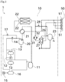
- FIG. 1 is a refrigerant circuit diagram of the heat pump 1.
- the heat pump 1 includes an outdoor unit 10 and an indoor unit 50.
- the heat pump 1 can raise or lower the temperature of air in a room where the indoor unit 50 is placed by performing heat exchange between outdoor heat exchangers 22 of the outdoor unit 10 and indoor heat exchangers 51 of the indoor unit 50 using a refrigerant.
- the outdoor unit 10 includes an engine 12 and a compressor motor 15 as power sources.
- the engine 12 is a gas engine, which generates power by burning supplied gas and drives two engine-driven compressors 13.
- the number of engine-driven compressors 13 driven by the engine 12 may be one or be three or more.
- Fuel for the engine 12 is not limited to gas and may be, for example, gasoline or light oil.
- the compressor motor 15 generates power using supplied power and drives one electric compressor 16.
- the compressor motor 15 may drive a plurality of electric compressors 16.
- the heat pump 1 according to the present embodiment is a hybrid heat pump, where an engine and an electric motor drive compressors.
- the heat pump 1 may include a plurality of engines 12 and/or a plurality of compressor motors 15.
- the engine-driven compressors 13 and the electric compressor 16 suck the refrigerant, which is in a gaseous form, from an accumulator 11.
- the accumulator 11 is a member for storing the gaseous refrigerant.
- the refrigerant is in a low-temperature and low-pressure gaseous form.
- the refrigerant in the accumulator 11 becomes a high-temperature and high-pressure gaseous form by being compressed by the engine-driven compressors 13 and the electric compressor 16.
- the engine-driven compressors 13 discharge the refrigerant to an oil separator 20 through a first check valve 14.
- the electric compressor 16 discharges the refrigerant to the oil separator 20 through a second check valve 17.
- the oil separator 20 separates lubricating oil for the engine-driven compressors 13 and the electric compressor 16 from the gaseous refrigerant.
- the separated lubricating oil is returned to the engine-driven compressors 13 and the electric compressor 16 through an unillustrated circuit.
- the gaseous refrigerant from which the lubricating oil is separated by the oil separator 20 is supplied to a four-way valve 21.
- the four-way valve 21 includes four ports and varies the destination of the supply of the refrigerant for heating and cooling. First, flow of the refrigerant during heating is described.
- the four-way valve 21 supplies the gaseous refrigerant to the indoor heat exchangers 51 as indicated with the solid lines in FIG. 1 .
- the indoor heat exchanger 51 performs heat exchange for transferring heat from the refrigerant to indoor air. This heat exchange raises the temperature of the indoor air. This heat exchange also changes the refrigerant into a form of low-temperature and high-pressure liquid.
- the number of the indoor heat exchangers 51 provided is two, which may, however, be one or be three or more.
- the refrigerant that has changed into a liquid form through the heat exchange by the indoor heat exchangers 51 is supplied to a receiver 23 through third check valves 26.
- the receiver 23 is a member for storing the liquid refrigerant.
- the refrigerant supplied to the receiver 23 flows through fourth check valves 27 and then through a first expansion valve 31 or a second expansion valve 32 to be supplied to the outdoor heat exchangers 22.
- the liquid refrigerant becomes like mists and low in pressure by flowing through the first expansion valve 31 or the second expansion valve 32.
- the two outdoor heat exchangers 22 are provided.
- the number of the outdoor heat exchangers 22 may be one or be three or more.
- the outdoor heat exchangers 22 perform heat exchange for transferring heat from outdoor air to the refrigerant. This heat exchange changes the refrigerant into a gaseous form.
- the gaseous refrigerant is supplied to the accumulator 11 through the four-way valve 21.
- the gaseous refrigerant is stored in the accumulator 11.
- the four-way valve 21 supplies the gaseous refrigerant to the outdoor heat exchangers 22 as indicated with the chain lines in FIG. 1 .
- the outdoor heat exchangers 22 perform heat exchange for transferring heat from the refrigerant to outdoor air. This heat exchange changes the refrigerant into a form of low-temperature and high-pressure liquid.
- the refrigerant that has changed into a liquid form through the heat exchange by the outdoor heat exchangers 22 is supplied to the receiver 23 through a fifth check valve 28.
- the liquid refrigerant supplied to the receiver 23 is supplied to the indoor heat exchangers 51.
- the indoor heat exchangers 51 perform heat exchange for transferring heat from indoor air to the refrigerant. This heat exchange lowers the temperature of the indoor air. This heat exchange also changes the refrigerant into a form of low-temperature and low-pressure gas.
- the refrigerant that has undergone the heat exchange by the indoor heat exchangers 51 is supplied to the accumulator 11 through the four-way valve 21.
- the gaseous refrigerant is stored in the accumulator 11.
- FIG. 2 is a block diagram illustrating the electrical configuration of the heat pump 1.
- actuators that are driven with electricity and exclude the electric compressor 16 and the compressor motor 15 may be simply referred to as "electric actuators.”
- the heat pump 1 includes a main controller 61.
- the main controller 61 is a computer including a CPU, RAM, ROM, and the like, and controls the units in the heat pump 1 by causing programs stored in the ROM to be read out to the RAM and executing the programs.
- the main controller 61 controls operations of a cooling water pump 12a, a starter motor 12b, the compressor motor 15, a first fan 71, a second fan 72, and a third fan 73. In the control that the main controller 61 performs on the operations, specifically, whether to drive each unit is changed and output during driving is changed.
- the cooling water pump 12a is a component for circulating cooling water in the engine 12.
- the main controller 61 basically continues to drive the cooling water pump 12a while the engine 12 is driven.
- the starter motor 12b is a component for starting the engine 12. Accordingly, the main controller 61 drives the starter motor 12b at a timing of starting the engine 12 and stops driving the starter motor 12b after the starting of the engine 12.
- the main controller 61 can adjust the output of the engine 12 by changing the amount of gas to be supplied to a cylinder, or the like.
- the main controller 61 controls the operation of the compressor motor 15 using the motor controller 62, which is another hardware. By controlling the operation of the compressor motor 15, the main controller 61 can change whether to drive the compressor motor 15 and change the output during driving.
- the first fan 71, the second fan 72, and the third fan 73 are provided near the outdoor heat exchangers 22 of the outdoor unit 10.
- the first fan 71, the second fan 72, and the third fan 73 are components for increasing the efficiency of heat exchange between outdoor air and the outdoor heat exchangers 22.
- the main controller 61 basically continues to drive the first fan 71, the second fan 72, and the third fan 73.
- the main controller 61 may be disposed in the indoor unit 50 or disposed at still another position. In the present embodiment, the main controller 61 is provided for each heat pump 1. A single main controller 61 may control a plurality of heat pumps 1.
- the main controller 61 and the motor controller 62 may be configured from the same hardware.
- the main controller 61 may control the engine 12, the first fan 71, the second fan 72, and the third fan 73 using another hardware.
- Electric actuators are supplied with power from power supply equipment, such as power transmission lines of a building, or the like. These electric actuators are started using the power from the power supply equipment by receiving, for example, predetermined starting signals from the main controller 61.
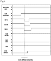
- FIG. 3 is a timing chart illustrating control performed by the main controller 61 in this case.
- an engine operation request indicates a result of determination on whether the main controller 61 operates the engine 12, based on which of the engine 12 and the electric compressor 16 takes precedence in being driven, requested air conditioning performance, and the like.
- an electric operation request indicates a result of determination on whether the main controller 61 operates the electric compressor 16, based on the above-named matters.
- the engine operation request and the electric operation request indicate "ON" when their objects are operated and indicate "OFF" when they are not operated.
- the main controller 61 starts the first fan 71 first after the engine operation request turns ON. After the completion of the starting of the first fan 71, that is, after the output of the first fan 71 becomes constant, the main controller 61 starts the second fan 72. Similarly, the main controller 61 starts the third fan 73 after the completion of the starting of the second fan 72. Next, the main controller 61 starts the cooling water pump 12a after the completion of the starting of the third fan 73.
- an electric actuator consumes a large amount of power at the time of being started.
- the main controller 61 stops driving the first fan 71, the second fan 72, the third fan 73, and the cooling water pump 12a in unison. Since a problem of power consumption is not caused when driving the electric actuators is stopped, the main controller 61 stops driving these electric actuators in unison. The main controller 61 drives the starter motor 12b after the completion of the stopping of driving these electric actuators.
- the starter motor 12b is assumed to be driven only for a short time.
- the main controller 61 drives the starter motor 12b again if the engine 12 is not started even after the starter motor 12b is driven.
- FIG. 3 presents an example in which the engine 12 is successfully started after driving the starter motor 12b three times.
- a timing that is after the engine operation request turns ON from OFF and a process related to the starting of the engine 12 is started and before the engine 12 is actually started is referred to as an "engine starting timing" (see FIG. 3 ).
- the main controller 61 starts the first fan 71, the second fan 72, the third fan 73, and the cooling water pump 12a, sequentially.
- the main controller 61 temporarily lowers output to zero at an engine starting timing by stopping driving the first fan 71, the second fan 72, the third fan 73, and the cooling water pump 12a, and raises the output after the starting of the engine 12 (in engine starting control).
- Driving the starter motor 12b needs a large amount of power. When this engine starting control is performed, however, concentration of power consumption at a timing can be prevented and accordingly, instantaneous increase in power consumption can be avoided.
- the output of the first fan 71, the second fan 72, and the third fan 73 at an engine starting timing is smaller than the output of the first fan 71, the second fan 72, and the third fan 73 after the starting of the engine 12.
- concentration of power consumption at a timing can be prevented. Accordingly, instantaneous increase in power consumption can be avoided.
- a process for lowering the output of an electric actuator is performed at an engine starting timing, and raises and restores the output of the electric actuator after the starting of the engine 12.
- the output of an electric actuator may be maintained at zero (that is, its starting is put on stanby), and after the starting of the engine 12, the output of the electric actuator may be raised to start the electric actuator.
- the engine starting control while the electric compressor 16 is not driven is performed on the first fan 71, the second fan 72, the third fan 73, and the cooling water pump 12a.
- the engine starting control is performed on an electric actuator driven if the heat pump 1 is driven and on an electric actuator driven if the engine 12 is driven.
- the engine starting control in this state may also be performed on an electric actuator driven if the electric compressor 16 is driven.
- FIG. 4 is a timing chart illustrating control performed by the main controller 61 in this case.
- the main controller 61 starts the first fan 71, the second fan 72, and the third fan 73, sequentially, so that the output thereof may become smaller than that during a normal time.
- the output during a normal time of an electric actuator herein represents the output that is set if a process for suppressing the output of an electric actuator is not performed, such as the engine starting control, the electric compressor starting control, or the like.
- a target value of the output of each electric actuator is set, for example, based on a value detected by a sensor, and the output with the target value constitutes the output during a normal time.
- the output constitutes the output during a normal time.
- the cooling water pump 12a is not started since there is no need to drive the cooling water pump 12a while the electric compressor 16 is driven.
- the main controller 61 initiates starting of the electric compressor 16 after the completion of the starting of the third fan 73. As illustrated in FIG. 4 , the main controller 61 raises the output of the electric compressor 16 in stages. In the present embodiment, a timing that is after the electric operation request turns ON from OFF so that a process related to the starting of the electric compressor 16 is started and before the output of the electric compressor 16 reaches target output is referred to as an "electric compressor starting timing.” Thus, when the output of the electric compressor 16 is increased in stages to reach the target output, the reach at the target output is regarded as completion of the starting of the electric compressor 16.
- the target output indicates target output for starting the electric compressor 16 and does not indicate target output changed with surrounding situations, various requests, and the like after the starting of the electric compressor 16.
- the main controller 61 raises the output of the electric compressor 16 to a first output value from zero while maintaining the output of the first fan 71, the second fan 72, and the third fan 73.
- the first output value is a value before the reach at target output (a second output value) by raising the output of the electric compressor 16 in stages to the target output. Accordingly, the first output value is smaller than the second output value, which is the target output of the electric compressor 16.
- the main controller 61 raises the output of the first fan 71, the second fan 72, and the third fan 73 concurrently to the output during a normal time while maintaining the output of the electric compressor 16 at the first output value.
- the main controller 61 raises the output of the electric compressor 16 to the target output.
- Power needed to start the electric compressor 16 is smaller than power needed to drive the starter motor 12b.
- the main controller 61 drives the first fan 71, the second fan 72, and the third fan 73 even if the output of the electric compressor 16 is raised from zero.
- the output of the first fan 71, the second fan 72, and the third fan 73 is smaller than that during a normal time.
- concentration of power consumption at a timing can be prevented by causing the output of an electric actuator to be lower than that during a normal time. Accordingly, instantaneous increase in power consumption can be avoided.
- FIG. 5 is a timing chart illustrating control performed by the main controller 61 in this case.
- the driven state of each unit before the engine operation request turns ON is the same as that after the starting of the electric compressor 16 in FIG. 4 .
- the main controller 61 stops driving the first fan 71, the second fan 72, and the third fan 73 and, at the same time, lowers the output of the electric compressor 16.
- the main controller 61 drives the starter motor 12b.
- the main controller 61 may lower the output of part or all of the first fan 71, the second fan 72, and the third fan 73 to a predetermined output value (# 0).
- the main controller 61 After the engine 12 is started by driving the starter motor 12b, the main controller 61 returns the output of the first fan 71, the second fan 72, and the third fan 73 concurrently to the output during a normal time. After all the output of the first fan 71, the second fan 72, and the third fan 73 is returned to the output during a normal time, the main controller 61 returns the output of the electric compressor 16 to preceding target output, which is the output immediately after the engine operation request turned ON.
- the main controller 61 temporarily lowers output of the first fan 71, the second fan 72, and the third fan 73 to zero by stopping driving the first fan 71, the second fan 72, and the third fan 73, and temporarily lowers the output of the electric compressor 16 to a predetermined value, and after the starting of the engine 12, the main controller 61 raises the output (in the engine starting control).
- the main controller 61 may perform control for starting the first fan 71, the second fan 72, and the third fan 73, sequentially. In contrast, when the engine 12 is started while the electric operation request is OFF ( FIG. 3 ), the main controller 61 may perform control for starting the first fan 71, the second fan 72, and the third fan 73 in unison.
- the engine starting control while the electric compressor 16 is driven is performed on the first fan 71, the second fan 72, the third fan 73, and the electric compressor 16.
- the objects of the engine starting control may exclude the first fan 71, the second fan 72, and the third fan 73, may further include another electric actuator, or may exclude the electric compressor 16.
- FIG. 6 is a timing chart illustrating control performed by the main controller 61 in this case.
- the driven state of each unit while the electric operation request is OFF is the same as that after the starting of the engine 12 in FIG. 3 .
- the main controller 61 stops driving the first fan 71, the second fan 72, and the third fan 73 in unison and makes the output thereof zero.
- necessary power is smaller than that of the first fan 71, the second fan 72, and the third fan 73 and is less influential and thus, the same output as that during a normal time is maintained.
- the main controller 61 raises the output of the electric compressor 16 after stopping driving all the first fan 71, the second fan 72, and the third fan 73. At this time, unlike FIG. 4 , the electric compressor 16 raises the output to target output in one go rather than in stages. After the output of the electric compressor 16 has risen to the target output, the main controller 61 starts the first fan 71, the second fan 72, and the third fan 73, sequentially, and raises the output thereof to the output during a normal time.
- the main controller 61 temporarily lowers the output of the first fan 71, the second fan 72, and the third fan 73 to zero by stopping driving the first fan 71, the second fan 72, and the third fan 73 and, after the starting of the electric compressor 16, raises the output (in the electric compressor starting control).
- the first fan 71, the second fan 72, and the third fan 73 are stopped at the time of starting the electric compressor 16 which is a time when necessary power increases. Therefore, concentration of power consumption at a timing can be prevented and accordingly, instantaneous increase in power consumption can be avoided.
- the heat pump 1 includes the engine 12, the electric compressor 16, the electric actuators different from the compressor motor 15 and the electric compressor 16, and the main controller 61.
- the engine 12 is started by the starter motor 12b and drives the engine-driven compressors 13.
- the electric compressor 16 is driven by the compressor motor.
- the main controller 61 performs the engine starting control and the electric compressor starting control. In the engine starting control, the main controller 61 lowers or maintains the output of at least one of the electric compressor 16 and the electric actuators at an engine starting timing, and raises the output thereof after the starting of the engine 12. In the electric compressor starting control, the main controller 61 lowers or maintains the output of the electric actuators at a starting timing of the electric compressor 16, and raises the output thereof after the starting of the electric compressor 16.
- concentration of power consumption at a timing can be prevented by lowering the output of the electric actuators and/or the electric compressor 16 or maintaining the output at a value lower than that during a normal time. Accordingly, instantaneous power consumption can be avoided.
- equipment suitable for the degree of the power consumption is required.
- the contract power may be decided, depending on the maximum power in a relatively short period (for example, in about a few minutes to an hour). Accordingly, as achieved by the heat pump 1 according to the present embodiment, the cost of power can be largely reduced simply by preventing instantaneous increase in power consumption.
- the output of at least one of the electric compressor 16 and the electric actuator that are driven is temporarily lowered at an engine starting timing.
- the output of the electric actuator that is driven is temporarily lowered at a starting timing of the electric compressor 16.
- the electric actuator includes the first fan 71, the second fan 72, and the third fan 73 for performing heat exchange.
- the main controller 61 raises the output of the first fan 71 after the starting of the engine 12 or the electric compressor 16. After that, the main controller 61 raises the output of the second fan 72 and subsequently raises the output of the third fan 73.
- concentration of power consumption at a timing can be prevented by varying the timings to raise the output of the plurality of fans. Accordingly, instantaneous power consumption can be further suppressed.
- the process of starting the electric actuator including the first fan 71, the second fan 72, the third fan 73, the cooling water pump 12a, and the like at an engine starting timing can be omitted.
- the output of these electric actuators is maintained at zero and, after the starting of the engine 12, the output is raised (in the engine starting control).
- the output of the electric actuators such as the first fan 71, the second fan 72, the third fan 73, and the like, may be temporarily raised and then lowered, and after the starting of the electric compressor 16, the output of the electric actuators may be raised (in the electric compressor starting control).
- the output may be maintained at zero and, after the starting of the electric compressor 16, the output may be raised.
- the output of the electric actuator may be maintained at zero or lowered at the engine starting timing, and after the starting of the engine 12, the output may be raised. At the starting of the electric compressor 16, the output may be raised in stages. The output of the electric compressor 16 may be raised earlier than the electric actuator.
- output of the cooling water pump 12a may be caused to be zero temporarily or lowered to a predetermined output value (# 0), which is lower than a value of a normal time.
- the output of the electric actuator is lowered to zero in the engine starting control and the electric compressor starting control ( FIGs. 3 , 5 , and 6 )
- the output may be lowered to a value that is not zero.
- the output of the electric compressor 16 is lowerd to a value that is not zero in the engine starting control ( FIG. 5 )
- the output of the electric compressor 16 may be lowered to zero. In this case, the electric compressor 16 is started again. Thus, the electric compressor starting control may be performed again at that time.
- the first fan 71, the second fan 72, and the third fan 73 are started one by one ( FIGs. 3 , 4 , and 6 )
- the first fan 71 and the second fan 72 may be started first concurrently and after that, the third fan 73 may be started.
- the first fan 71 may be started first and after that, the second fan 72 and the third fan 73 may be started concurrently.
- the fans may be started in units of two or more.
- the electric actuators described in the above-described embodiment are examples and at least one of the engine starting control and the electric compressor starting control may be performed on another electric actuator.
- Examples of such another electric actuator can include a heater that heats each unit of the heat pump 1.
- the heat pump 1 performs both the engine starting control and the electric compressor starting control, the heat pump 1 may be configured to perform only one of them.
- the heat pump 1 is applied to an air conditioner, it is also applicable to other configurations.
- the heat pump 1 is applicable to refrigerators, water heaters, or the like.
Landscapes
- Engineering & Computer Science (AREA)
- Mechanical Engineering (AREA)
- General Engineering & Computer Science (AREA)
- Physics & Mathematics (AREA)
- Combustion & Propulsion (AREA)
- Chemical & Material Sciences (AREA)
- Thermal Sciences (AREA)
- Fuzzy Systems (AREA)
- Mathematical Physics (AREA)
- Signal Processing (AREA)
- Fluid Mechanics (AREA)
- Control Of Vehicle Engines Or Engines For Specific Uses (AREA)
- Air Conditioning Control Device (AREA)
Abstract
Description
- The present invention relates to a heat pump including an engine-driven compressor driven by an engine and an electric compressor driven by a compressor motor.
- A hybrid heat pump including an engine-driven compressor and an electric compressor has been long known. Patent Literature 1 (hereinafter, PTL 1) and Patent Literature 2 (hereinafter, PTL 2) disclose such hybrid heat pumps.
-
PTL 1 describes that, based on air conditioning load, balance of output between a gas heat pump conditioner that uses an engine-driven compressor (a first compressor) and an electrical heat pump conditioner that uses an electric compressor (a second compressor) is decided.PTL 1 further describes that switching is performed between control where importance is placed on the efficiency or life of the gas heat pump conditioner and control where importance is placed on the life of the electrical heat pump conditioner and on suppression of increase in the amount of contract power (power consumption). - PTL 2 describes that a gas heat pump conditioner and an electrical heat pump conditioner are driven according to a predetermined schedule. PTL 2 further describes that only one of the gas heat pump conditioner and the electrical heat pump conditioner is driven.
-
- PTL 1: Japanese Patent Application Laid-Open No.
2007-187342 - PTL 2: Japanese Patent Application Laid-Open No.
2012-7867 - However, each of
PTL 1 and PTL 2 merely describes that the output ratio between the gas heat pump conditioner and the electrical heat pump conditioner is adjusted so as to suppress increase in power consumption. Even if power consumption increases only instantaneously, suitable equipment, electrical contract, or the like for the degree of power consumption is required. - The present invention has been made in view of such circumstances and its main object is to provide a configuration for suppressing instantaneous increase in power consumption in a hybrid heat pump including an engine-driven compressor and an electric compressor.
- Problems to be solved by the invention are as described above, and next, solutions for solving the problems and advantages thereof will be described.
- In an aspect of the present invention, a heat pump having the following configuration is provided. That is, the heat pump includes an engine, an electric compressor, an electric actuator different from a compressor motor and the electric compressor, and a controller. The engine is configured to be started by a starter motor and drive an engine-driven compressor. The electric compressor is configured to be driven by the compressor motor. The controller is configured to perform at least one of engine starting control and electric compressor starting control. In the engine starting control, the controller lowers or maintains output of at least one of the electric compressor and the electric actuator at an engine starting timing, and raises the output of the at least one of the electric compressor and the electric actuator after starting of the engine. In the electric compressor starting control, the controller lowers or maintains output of the electric actuator at an electric compressor starting timing, and raises the output of the electric actuator after starting of the electric compressor.
- With the above-described configuration, at the engine starting timing or electric compressor starting timing, concentration of power consumption at a timing can be prevented by lowering output of another electrical apparatus or putting the starting of the apparatus on stanby. Accordingly, instantaneous increase in power consumption can be avoided.
- The heat pump may preferably be configured as follows. That is, when the engine starting control is performed, at the engine starting timing, the output of the at least one of the electric compressor and the electric actuator that are driven is temporarily lowered. When the electric compressor starting control is performed, at the electric compressor starting timing, the output of the electric actuator that is driven is temporarily lowered.
- Thus, even while the electric compressor or electric actuator is driven, concentration of power consumption at a timing can be prevented by temporarily lowering the output thereof. Accordingly, instantaneous increase in power consumption can be avoided.
- The heat pump may preferably be configured as follows. That is, the electric actuator includes a plurality of fans for performing heat exchange. When the controller performs at least one of the engine starting control and the electric compressor starting control, the controller raises output of at least one of the fans after the starting of the engine or the electric compressor, and subsequently raises output of the remaining one or more fans.
- Thus, concentration of power consumption at a timing can be prevented by varying timings to raise the output of the plurality of fans. Accordingly, instantaneous increase in power consumption can be avoided.
-
- [
FIG. 1 ] A refrigerant circuit diagram of a heat pump according to an embodiment of the present invention. - [
FIG. 2 ] A block diagram illustrating an electrical configuration of the heat pump. - [
FIG. 3 ] A timing chart illustrating a case where an engine is started while an electric compressor is not driven. - [
FIG. 4 ] A timing chart illustrating a case where the electric compressor is started while the engine is not driven. - [
FIG. 5 ] A timing chart illustrating a case where the engine is started while the electric compressor is driven. - [
FIG. 6 ] A timing chart illustrating a case where the electric compressor is started while the engine is driven. - Embodiments of the present invention are described below with reference to the drawings. First, an air conditioner that includes a
heat pump 1 according to an embodiment and is used for a building is described with reference toFIG. 1. FIG. 1 is a refrigerant circuit diagram of theheat pump 1. - As illustrated in
FIG. 1 , theheat pump 1 includes anoutdoor unit 10 and anindoor unit 50. Theheat pump 1 can raise or lower the temperature of air in a room where theindoor unit 50 is placed by performing heat exchange betweenoutdoor heat exchangers 22 of theoutdoor unit 10 andindoor heat exchangers 51 of theindoor unit 50 using a refrigerant. - The
outdoor unit 10 includes anengine 12 and acompressor motor 15 as power sources. Theengine 12 is a gas engine, which generates power by burning supplied gas and drives two engine-drivencompressors 13. The number of engine-drivencompressors 13 driven by theengine 12 may be one or be three or more. Fuel for theengine 12 is not limited to gas and may be, for example, gasoline or light oil. - The
compressor motor 15 generates power using supplied power and drives oneelectric compressor 16. Thecompressor motor 15 may drive a plurality ofelectric compressors 16. Thus, theheat pump 1 according to the present embodiment is a hybrid heat pump, where an engine and an electric motor drive compressors. Theheat pump 1 may include a plurality ofengines 12 and/or a plurality ofcompressor motors 15. - The engine-driven
compressors 13 and theelectric compressor 16 suck the refrigerant, which is in a gaseous form, from anaccumulator 11. Theaccumulator 11 is a member for storing the gaseous refrigerant. In theaccumulator 11, the refrigerant is in a low-temperature and low-pressure gaseous form. The refrigerant in theaccumulator 11 becomes a high-temperature and high-pressure gaseous form by being compressed by the engine-drivencompressors 13 and theelectric compressor 16. The engine-drivencompressors 13 discharge the refrigerant to anoil separator 20 through afirst check valve 14. Theelectric compressor 16 discharges the refrigerant to theoil separator 20 through asecond check valve 17. - The
oil separator 20 separates lubricating oil for the engine-drivencompressors 13 and theelectric compressor 16 from the gaseous refrigerant. The separated lubricating oil is returned to the engine-drivencompressors 13 and theelectric compressor 16 through an unillustrated circuit. The gaseous refrigerant from which the lubricating oil is separated by theoil separator 20 is supplied to a four-way valve 21. - The four-
way valve 21 includes four ports and varies the destination of the supply of the refrigerant for heating and cooling. First, flow of the refrigerant during heating is described. - During heating, the four-
way valve 21 supplies the gaseous refrigerant to theindoor heat exchangers 51 as indicated with the solid lines inFIG. 1 . Theindoor heat exchanger 51 performs heat exchange for transferring heat from the refrigerant to indoor air. This heat exchange raises the temperature of the indoor air. This heat exchange also changes the refrigerant into a form of low-temperature and high-pressure liquid. InFIG. 1 , the number of theindoor heat exchangers 51 provided is two, which may, however, be one or be three or more. The refrigerant that has changed into a liquid form through the heat exchange by theindoor heat exchangers 51 is supplied to areceiver 23 throughthird check valves 26. - The
receiver 23 is a member for storing the liquid refrigerant. The refrigerant supplied to thereceiver 23 flows throughfourth check valves 27 and then through afirst expansion valve 31 or asecond expansion valve 32 to be supplied to theoutdoor heat exchangers 22. The liquid refrigerant becomes like mists and low in pressure by flowing through thefirst expansion valve 31 or thesecond expansion valve 32. In theheat pump 1 according to the present embodiment, the twooutdoor heat exchangers 22 are provided. The number of theoutdoor heat exchangers 22 may be one or be three or more. - The
outdoor heat exchangers 22 perform heat exchange for transferring heat from outdoor air to the refrigerant. This heat exchange changes the refrigerant into a gaseous form. The gaseous refrigerant is supplied to theaccumulator 11 through the four-way valve 21. The gaseous refrigerant is stored in theaccumulator 11. - Next, flow of the refrigerant during cooling is described. During cooling, the four-
way valve 21 supplies the gaseous refrigerant to theoutdoor heat exchangers 22 as indicated with the chain lines inFIG. 1 . Theoutdoor heat exchangers 22 perform heat exchange for transferring heat from the refrigerant to outdoor air. This heat exchange changes the refrigerant into a form of low-temperature and high-pressure liquid. The refrigerant that has changed into a liquid form through the heat exchange by theoutdoor heat exchangers 22 is supplied to thereceiver 23 through afifth check valve 28. - The liquid refrigerant supplied to the
receiver 23 is supplied to theindoor heat exchangers 51. Theindoor heat exchangers 51 perform heat exchange for transferring heat from indoor air to the refrigerant. This heat exchange lowers the temperature of the indoor air. This heat exchange also changes the refrigerant into a form of low-temperature and low-pressure gas. The refrigerant that has undergone the heat exchange by theindoor heat exchangers 51 is supplied to theaccumulator 11 through the four-way valve 21. The gaseous refrigerant is stored in theaccumulator 11. - An electrical configuration of the
heat pump 1 is described below with reference toFIG. 2. FIG. 2 is a block diagram illustrating the electrical configuration of theheat pump 1. In the description below, actuators that are driven with electricity and exclude theelectric compressor 16 and thecompressor motor 15 may be simply referred to as "electric actuators." - As illustrated in
FIG. 2 , theheat pump 1 includes amain controller 61. Themain controller 61 is a computer including a CPU, RAM, ROM, and the like, and controls the units in theheat pump 1 by causing programs stored in the ROM to be read out to the RAM and executing the programs. Specifically, as illustrated inFIG. 2 , themain controller 61 controls operations of acooling water pump 12a, astarter motor 12b, thecompressor motor 15, afirst fan 71, asecond fan 72, and athird fan 73. In the control that themain controller 61 performs on the operations, specifically, whether to drive each unit is changed and output during driving is changed. - The cooling
water pump 12a is a component for circulating cooling water in theengine 12. Themain controller 61 basically continues to drive the coolingwater pump 12a while theengine 12 is driven. Thestarter motor 12b is a component for starting theengine 12. Accordingly, themain controller 61 drives thestarter motor 12b at a timing of starting theengine 12 and stops driving thestarter motor 12b after the starting of theengine 12. Themain controller 61 can adjust the output of theengine 12 by changing the amount of gas to be supplied to a cylinder, or the like. - The
main controller 61 controls the operation of thecompressor motor 15 using themotor controller 62, which is another hardware. By controlling the operation of thecompressor motor 15, themain controller 61 can change whether to drive thecompressor motor 15 and change the output during driving. - The
first fan 71, thesecond fan 72, and thethird fan 73 are provided near theoutdoor heat exchangers 22 of theoutdoor unit 10. Thefirst fan 71, thesecond fan 72, and thethird fan 73 are components for increasing the efficiency of heat exchange between outdoor air and theoutdoor heat exchangers 22. Thus, while theheat pump 1 is driven, themain controller 61 basically continues to drive thefirst fan 71, thesecond fan 72, and thethird fan 73. - Although disposed in the
outdoor unit 10 in the present embodiment, themain controller 61 may be disposed in theindoor unit 50 or disposed at still another position. In the present embodiment, themain controller 61 is provided for eachheat pump 1. A singlemain controller 61 may control a plurality ofheat pumps 1. - The
main controller 61 and themotor controller 62 may be configured from the same hardware. For another example, themain controller 61 may control theengine 12, thefirst fan 71, thesecond fan 72, and thethird fan 73 using another hardware. - Described below is how the
main controller 61 controls the operation of each unit in starting theengine 12 or theelectric compressor 16. Electric actuators according to the present embodiment are supplied with power from power supply equipment, such as power transmission lines of a building, or the like. These electric actuators are started using the power from the power supply equipment by receiving, for example, predetermined starting signals from themain controller 61. - First, a case where the
engine 12 is started while theelectric compressor 16 is not driven is described with reference toFIG. 3. FIG. 3 is a timing chart illustrating control performed by themain controller 61 in this case. - In
FIG. 3 and the drawings thereafter, an engine operation request indicates a result of determination on whether themain controller 61 operates theengine 12, based on which of theengine 12 and theelectric compressor 16 takes precedence in being driven, requested air conditioning performance, and the like. Similarly, an electric operation request indicates a result of determination on whether themain controller 61 operates theelectric compressor 16, based on the above-named matters. InFIG. 3 , the engine operation request and the electric operation request indicate "ON" when their objects are operated and indicate "OFF" when they are not operated. - When both the engine operation request and the electric operation request indicate OFF, none of the electric actuators depicted in
FIG. 3 is driven. After that, themain controller 61 starts thefirst fan 71 first after the engine operation request turns ON. After the completion of the starting of thefirst fan 71, that is, after the output of thefirst fan 71 becomes constant, themain controller 61 starts thesecond fan 72. Similarly, themain controller 61 starts thethird fan 73 after the completion of the starting of thesecond fan 72. Next, themain controller 61 starts the coolingwater pump 12a after the completion of the starting of thethird fan 73. Typically, an electric actuator consumes a large amount of power at the time of being started. Thus, as in the present embodiment, by varying timings to start thefirst fan 71, thesecond fan 72, thethird fan 73, and the coolingwater pump 12a, concentration of power consumption at a timing can be prevented and accordingly, instantaneous increase in power consumption can be avoided. - After that, the
main controller 61 stops driving thefirst fan 71, thesecond fan 72, thethird fan 73, and the coolingwater pump 12a in unison. Since a problem of power consumption is not caused when driving the electric actuators is stopped, themain controller 61 stops driving these electric actuators in unison. Themain controller 61 drives thestarter motor 12b after the completion of the stopping of driving these electric actuators. - The
starter motor 12b is assumed to be driven only for a short time. In the present embodiment, themain controller 61 drives thestarter motor 12b again if theengine 12 is not started even after thestarter motor 12b is driven.FIG. 3 presents an example in which theengine 12 is successfully started after driving thestarter motor 12b three times. In the present embodiment, a timing that is after the engine operation request turns ON from OFF and a process related to the starting of theengine 12 is started and before theengine 12 is actually started is referred to as an "engine starting timing" (seeFIG. 3 ). - Similart to the above, after the starting of the
engine 12, themain controller 61 starts thefirst fan 71, thesecond fan 72, thethird fan 73, and the coolingwater pump 12a, sequentially. Thus, in the present embodiment, themain controller 61 temporarily lowers output to zero at an engine starting timing by stopping driving thefirst fan 71, thesecond fan 72, thethird fan 73, and the coolingwater pump 12a, and raises the output after the starting of the engine 12 (in engine starting control). Driving thestarter motor 12b needs a large amount of power. When this engine starting control is performed, however, concentration of power consumption at a timing can be prevented and accordingly, instantaneous increase in power consumption can be avoided. - The output of the
first fan 71, thesecond fan 72, and thethird fan 73 at an engine starting timing is smaller than the output of thefirst fan 71, thesecond fan 72, and thethird fan 73 after the starting of theengine 12. Thus, even if thestarter motor 12b is driven before the output of thefirst fan 71, thesecond fan 72, and thethird fan 73 turns zero, concentration of power consumption at a timing can be prevented. Accordingly, instantaneous increase in power consumption can be avoided. - In the engine starting control according to the present embodiment, a process for lowering the output of an electric actuator is performed at an engine starting timing, and raises and restores the output of the electric actuator after the starting of the
engine 12. Instead, at an engine starting timing, the output of an electric actuator may be maintained at zero (that is, its starting is put on stanby), and after the starting of theengine 12, the output of the electric actuator may be raised to start the electric actuator. - Thus, in the present embodiment, the engine starting control while the
electric compressor 16 is not driven is performed on thefirst fan 71, thesecond fan 72, thethird fan 73, and the coolingwater pump 12a. In other words, the engine starting control is performed on an electric actuator driven if theheat pump 1 is driven and on an electric actuator driven if theengine 12 is driven. The engine starting control in this state may also be performed on an electric actuator driven if theelectric compressor 16 is driven. - Next, a case where the
electric compressor 16 is started while theengine 12 is not driven is described with reference toFIG. 4. FIG. 4 is a timing chart illustrating control performed by themain controller 61 in this case. - Similar to
FIG. 3 , when the electric operation request turns ON from OFF, themain controller 61 starts thefirst fan 71, thesecond fan 72, and thethird fan 73, sequentially, so that the output thereof may become smaller than that during a normal time. The output during a normal time of an electric actuator herein represents the output that is set if a process for suppressing the output of an electric actuator is not performed, such as the engine starting control, the electric compressor starting control, or the like. For example, a target value of the output of each electric actuator is set, for example, based on a value detected by a sensor, and the output with the target value constitutes the output during a normal time. For another example, when an electric actuator is continuously driven with a constant output without using a value detected by a sensor, the output constitutes the output during a normal time. The coolingwater pump 12a is not started since there is no need to drive the coolingwater pump 12a while theelectric compressor 16 is driven. - The
main controller 61 initiates starting of theelectric compressor 16 after the completion of the starting of thethird fan 73. As illustrated inFIG. 4 , themain controller 61 raises the output of theelectric compressor 16 in stages. In the present embodiment, a timing that is after the electric operation request turns ON from OFF so that a process related to the starting of theelectric compressor 16 is started and before the output of theelectric compressor 16 reaches target output is referred to as an "electric compressor starting timing." Thus, when the output of theelectric compressor 16 is increased in stages to reach the target output, the reach at the target output is regarded as completion of the starting of theelectric compressor 16. Herein, the target output indicates target output for starting theelectric compressor 16 and does not indicate target output changed with surrounding situations, various requests, and the like after the starting of theelectric compressor 16. - After the completion of the starting of the
third fan 73, themain controller 61 raises the output of theelectric compressor 16 to a first output value from zero while maintaining the output of thefirst fan 71, thesecond fan 72, and thethird fan 73. The first output value is a value before the reach at target output (a second output value) by raising the output of theelectric compressor 16 in stages to the target output. Accordingly, the first output value is smaller than the second output value, which is the target output of theelectric compressor 16. After causing the output of theelectric compressor 16 to reach the first output value, themain controller 61 raises the output of thefirst fan 71, thesecond fan 72, and thethird fan 73 concurrently to the output during a normal time while maintaining the output of theelectric compressor 16 at the first output value. After the output of thefirst fan 71, thesecond fan 72, and thethird fan 73 reaches the output during a normal time, themain controller 61 raises the output of theelectric compressor 16 to the target output. - Power needed to start the
electric compressor 16 is smaller than power needed to drive thestarter motor 12b. Thus, at a starting timing of theelectric compressor 16, themain controller 61 drives thefirst fan 71, thesecond fan 72, and thethird fan 73 even if the output of theelectric compressor 16 is raised from zero. At an electric compressor starting timing, the output of thefirst fan 71, thesecond fan 72, and thethird fan 73 is smaller than that during a normal time. Thus, at an electric compressor starting timing, concentration of power consumption at a timing can be prevented by causing the output of an electric actuator to be lower than that during a normal time. Accordingly, instantaneous increase in power consumption can be avoided. - Next, a case where the
engine 12 is started while theelectric compressor 16 is driven is described with reference toFIG. 5. FIG. 5 is a timing chart illustrating control performed by themain controller 61 in this case. - The driven state of each unit before the engine operation request turns ON is the same as that after the starting of the
electric compressor 16 inFIG. 4 . When the engine operation request turns ON from this state, themain controller 61 stops driving thefirst fan 71, thesecond fan 72, and thethird fan 73 and, at the same time, lowers the output of theelectric compressor 16. After stopping thefirst fan 71, thesecond fan 72, and thethird fan 73 and lowering the output of theelectric compressor 16 are completed, themain controller 61 drives thestarter motor 12b. After the engine operation request turns ON, themain controller 61 may lower the output of part or all of thefirst fan 71, thesecond fan 72, and thethird fan 73 to a predetermined output value (# 0). - After the
engine 12 is started by driving thestarter motor 12b, themain controller 61 returns the output of thefirst fan 71, thesecond fan 72, and thethird fan 73 concurrently to the output during a normal time. After all the output of thefirst fan 71, thesecond fan 72, and thethird fan 73 is returned to the output during a normal time, themain controller 61 returns the output of theelectric compressor 16 to preceding target output, which is the output immediately after the engine operation request turned ON. - Thus, in the present embodiment, at an engine starting timing, the
main controller 61 temporarily lowers output of thefirst fan 71, thesecond fan 72, and thethird fan 73 to zero by stopping driving thefirst fan 71, thesecond fan 72, and thethird fan 73, and temporarily lowers the output of theelectric compressor 16 to a predetermined value, and after the starting of theengine 12, themain controller 61 raises the output (in the engine starting control). - When the
engine 12 is started while the electric operation request is ON (FIG. 5 ), themain controller 61 may perform control for starting thefirst fan 71, thesecond fan 72, and thethird fan 73, sequentially. In contrast, when theengine 12 is started while the electric operation request is OFF (FIG. 3 ), themain controller 61 may perform control for starting thefirst fan 71, thesecond fan 72, and thethird fan 73 in unison. - Thus, in the present embodiment, the engine starting control while the
electric compressor 16 is driven is performed on thefirst fan 71, thesecond fan 72, thethird fan 73, and theelectric compressor 16. The objects of the engine starting control may exclude thefirst fan 71, thesecond fan 72, and thethird fan 73, may further include another electric actuator, or may exclude theelectric compressor 16. - Next, a case where the
electric compressor 16 is started while theengine 12 is driven is described with reference toFIG. 6. FIG. 6 is a timing chart illustrating control performed by themain controller 61 in this case. - The driven state of each unit while the electric operation request is OFF is the same as that after the starting of the
engine 12 inFIG. 3 . When the electric operation request turns ON from this state, themain controller 61 stops driving thefirst fan 71, thesecond fan 72, and thethird fan 73 in unison and makes the output thereof zero. As for the coolingwater pump 12a, necessary power is smaller than that of thefirst fan 71, thesecond fan 72, and thethird fan 73 and is less influential and thus, the same output as that during a normal time is maintained. - The
main controller 61 raises the output of theelectric compressor 16 after stopping driving all thefirst fan 71, thesecond fan 72, and thethird fan 73. At this time, unlikeFIG. 4 , theelectric compressor 16 raises the output to target output in one go rather than in stages. After the output of theelectric compressor 16 has risen to the target output, themain controller 61 starts thefirst fan 71, thesecond fan 72, and thethird fan 73, sequentially, and raises the output thereof to the output during a normal time. - Thus, in the present embodiment, at an electric compressor starting timing, the
main controller 61 temporarily lowers the output of thefirst fan 71, thesecond fan 72, and thethird fan 73 to zero by stopping driving thefirst fan 71, thesecond fan 72, and thethird fan 73 and, after the starting of theelectric compressor 16, raises the output (in the electric compressor starting control). Thus, thefirst fan 71, thesecond fan 72, and thethird fan 73 are stopped at the time of starting theelectric compressor 16 which is a time when necessary power increases. Therefore, concentration of power consumption at a timing can be prevented and accordingly, instantaneous increase in power consumption can be avoided. - As described above, the
heat pump 1 according to the present embodiment includes theengine 12, theelectric compressor 16, the electric actuators different from thecompressor motor 15 and theelectric compressor 16, and themain controller 61. Theengine 12 is started by thestarter motor 12b and drives the engine-drivencompressors 13. Theelectric compressor 16 is driven by the compressor motor. Themain controller 61 performs the engine starting control and the electric compressor starting control. In the engine starting control, themain controller 61 lowers or maintains the output of at least one of theelectric compressor 16 and the electric actuators at an engine starting timing, and raises the output thereof after the starting of theengine 12. In the electric compressor starting control, themain controller 61 lowers or maintains the output of the electric actuators at a starting timing of theelectric compressor 16, and raises the output thereof after the starting of theelectric compressor 16. - With the above-described configuration, at an engine starting timing or electric compressor starting timing, concentration of power consumption at a timing can be prevented by lowering the output of the electric actuators and/or the
electric compressor 16 or maintaining the output at a value lower than that during a normal time. Accordingly, instantaneous power consumption can be avoided. Typically, even if power consumption increases only instantaneously, equipment suitable for the degree of the power consumption is required. In an electrical contract, the contract power may be decided, depending on the maximum power in a relatively short period (for example, in about a few minutes to an hour). Accordingly, as achieved by theheat pump 1 according to the present embodiment, the cost of power can be largely reduced simply by preventing instantaneous increase in power consumption. - Further, when the engine starting control is performed in the
heat pump 1 according to the present embodiment, the output of at least one of theelectric compressor 16 and the electric actuator that are driven is temporarily lowered at an engine starting timing. When the electric compressor starting control is performed, the output of the electric actuator that is driven is temporarily lowered at a starting timing of theelectric compressor 16. - Thus, even while the
electric compressor 16 or the electric actuator are driven, concentration of power consumption at a timing can be prevented by temporarily lowering the output thereof. Accordingly, instantaneous power consumption can be avoided. - Moreover, in the
heat pump 1 according to the present embodiment, the electric actuator includes thefirst fan 71, thesecond fan 72, and thethird fan 73 for performing heat exchange. In performing at least one of the engine starting control and the electric compressor starting control, themain controller 61 raises the output of thefirst fan 71 after the starting of theengine 12 or theelectric compressor 16. After that, themain controller 61 raises the output of thesecond fan 72 and subsequently raises the output of thethird fan 73. - Thus, concentration of power consumption at a timing can be prevented by varying the timings to raise the output of the plurality of fans. Accordingly, instantaneous power consumption can be further suppressed.
- Although a preferred embodiment of the present invention has been described above, the above-described configuration can be modified, for example, as follows.
- When the
engine 12 is started while theelectric compressor 16 is not driven (FIG. 3 ), the process of starting the electric actuator including thefirst fan 71, thesecond fan 72, thethird fan 73, the coolingwater pump 12a, and the like at an engine starting timing can be omitted. In this case, at the engine starting timing, the output of these electric actuators is maintained at zero and, after the starting of theengine 12, the output is raised (in the engine starting control). - When the
electric compressor 16 is started while theengine 12 is not driven (FIG. 4 ), at an electric compressor starting timing, similar toFIG. 3 , the output of the electric actuators, such as thefirst fan 71, thesecond fan 72, thethird fan 73, and the like, may be temporarily raised and then lowered, and after the starting of theelectric compressor 16, the output of the electric actuators may be raised (in the electric compressor starting control). At the electric compressor starting timing, the output may be maintained at zero and, after the starting of theelectric compressor 16, the output may be raised. - When the
engine 12 is started while theelectric compressor 16 is driven (FIG. 5 ) and if any electric actuator is driven at the time of driving theelectric compressor 16, the output of the electric actuator may be maintained at zero or lowered at the engine starting timing, and after the starting of theengine 12, the output may be raised. At the starting of theelectric compressor 16, the output may be raised in stages. The output of theelectric compressor 16 may be raised earlier than the electric actuator. - When the
electric compressor 16 is started while theengine 12 is driven (FIG. 6 ), at the engine starting timing, output of the coolingwater pump 12a may be caused to be zero temporarily or lowered to a predetermined output value (# 0), which is lower than a value of a normal time. - Although, in the above-described embodiment, the output of the electric actuator is lowered to zero in the engine starting control and the electric compressor starting control (
FIGs. 3 ,5 , and6 ), the output may be lowered to a value that is not zero. Although, in the above-described embodiment, the output of theelectric compressor 16 is lowerd to a value that is not zero in the engine starting control (FIG. 5 ), the output of theelectric compressor 16 may be lowered to zero. In this case, theelectric compressor 16 is started again. Thus, the electric compressor starting control may be performed again at that time. - Although the above-described embodiment describes an example where the
first fan 71, thesecond fan 72, and thethird fan 73 are started one by one (FIGs. 3 ,4 , and6 ), thefirst fan 71 and thesecond fan 72 may be started first concurrently and after that, thethird fan 73 may be started. For another example, thefirst fan 71 may be started first and after that, thesecond fan 72 and thethird fan 73 may be started concurrently. Depending on the number of fans, the fans may be started in units of two or more. - The electric actuators described in the above-described embodiment are examples and at least one of the engine starting control and the electric compressor starting control may be performed on another electric actuator. Examples of such another electric actuator can include a heater that heats each unit of the
heat pump 1. - Although the
heat pump 1 according to the above-described embodiment performs both the engine starting control and the electric compressor starting control, theheat pump 1 may be configured to perform only one of them. - Although the above-described embodiment describes an example where the
heat pump 1 is applied to an air conditioner, it is also applicable to other configurations. For example, theheat pump 1 is applicable to refrigerators, water heaters, or the like. -
- 1
- heat pump
- 10
- outdoor unit
- 12
- engine
- 13
- engine-driven compressor
- 15
- compressor motor
- 16
- electric compressor
- 12a
- cooling water pump (electric actuator)
- 61
- main controller (controller)
- 71
- first fan (electric actuator)
- 72
- second fan (electric actuator)
- 73
- third fan (electric actuator)
Claims (4)
- A heat pump comprising:an engine configured to be started by a starter motor and drive an engine-driven compressor;an electric compressor configured to be driven by a compressor motor;an electric actuator different from the compressor motor and the electric compressor; anda controller configured to perform at least one of engine starting control and electric compressor starting control, whereinin the engine starting control, the controller lowers or maintains output of at least one of the electric compressor and the electric actuator at an engine starting timing, and raises the output of the at least one of the electric compressor and the electric actuator after starting of the engine, andin the electric compressor starting control, the controller lowers or maintains output of the electric actuator at an electric compressor starting timing, and raises the output of the electric actuator after starting of the electric compressor.
- The heat pump according to claim 1, wherein
when the controller performs the engine starting control, at the engine starting timing, the controller temporarily lowers the output of the at least one of the electric compressor and the electric actuator that are driven, and
when the controller performs the electric compressor starting control, at the electric compressor starting timing, the controller temporarily lowers the output of the electric actuator that is driven. - The heat pump according to claim 1, wherein
the electric actuator includes a plurality of fans for performing heat exchange, and
when the controller performs the at least one of the engine starting control and the electric compressor starting control, the controller raises output of at least one of the fans after the starting of the engine or the electric compressor, and subsequently raises output of the remaining one or more fans. - The heat pump according to claim 2, wherein
the electric actuator includes a plurality of fans for performing heat exchange, and
when the controller performs the at least one of the engine starting control and the electric compressor starting control, the controller raises output of at least one of the fans after the starting of the engine or the electric compressor, and subsequently raises output of the remaining one or more fans.
Applications Claiming Priority (2)
| Application Number | Priority Date | Filing Date | Title |
|---|---|---|---|
| JP2017061547A JP6767906B2 (en) | 2017-03-27 | 2017-03-27 | heat pump |
| PCT/JP2018/007664 WO2018180161A1 (en) | 2017-03-27 | 2018-02-28 | Heat pump |
Publications (3)
| Publication Number | Publication Date |
|---|---|
| EP3598024A1 true EP3598024A1 (en) | 2020-01-22 |
| EP3598024A4 EP3598024A4 (en) | 2020-12-23 |
| EP3598024B1 EP3598024B1 (en) | 2024-05-22 |
Family
ID=63675431
Family Applications (1)
| Application Number | Title | Priority Date | Filing Date |
|---|---|---|---|
| EP18776762.9A Active EP3598024B1 (en) | 2017-03-27 | 2018-02-28 | Heat pump |
Country Status (5)
| Country | Link |
|---|---|
| EP (1) | EP3598024B1 (en) |
| JP (1) | JP6767906B2 (en) |
| KR (1) | KR102225432B1 (en) |
| CN (1) | CN110431363B (en) |
| WO (1) | WO2018180161A1 (en) |
Families Citing this family (2)
| Publication number | Priority date | Publication date | Assignee | Title |
|---|---|---|---|---|
| JP2020200958A (en) * | 2019-06-06 | 2020-12-17 | シャープ株式会社 | Air conditioner |
| JP2026068965A (en) * | 2024-10-11 | 2026-04-23 | パナソニックIpマネジメント株式会社 | Air conditioning system, control method for air conditioning system, and control program for air conditioning system |
Family Cites Families (14)
| Publication number | Priority date | Publication date | Assignee | Title |
|---|---|---|---|---|
| JPS58138938A (en) * | 1982-02-15 | 1983-08-18 | Matsushita Electric Ind Co Ltd | Air conditioner |
| JPS6110978A (en) * | 1984-06-27 | 1986-01-18 | Toshiba Corp | Parallel starting and operating method of motor driven compressor group operated in parallel |
| JP2557903B2 (en) * | 1987-09-10 | 1996-11-27 | 株式会社東芝 | Air conditioner |
| JP2845515B2 (en) * | 1989-10-02 | 1999-01-13 | 株式会社東芝 | Integrated air conditioner |
| JPH07305904A (en) * | 1994-05-11 | 1995-11-21 | Matsushita Refrig Co Ltd | Freezer |
| KR100423970B1 (en) * | 2001-11-24 | 2004-03-22 | 삼성전자주식회사 | Air conditioner and control method thereof |
| JP4951976B2 (en) | 2006-01-11 | 2012-06-13 | ダイキン工業株式会社 | Air conditioner group control device |
| JP2008267643A (en) * | 2007-04-17 | 2008-11-06 | Sanyo Electric Co Ltd | Air conditioner and engine start method of air conditioner |
| JP5491987B2 (en) | 2010-06-28 | 2014-05-14 | ダイキン工業株式会社 | Air conditioning controller |
| JP2012007868A (en) * | 2010-06-28 | 2012-01-12 | Daikin Industries Ltd | Air conditioning controller |
| JP2013231523A (en) * | 2012-04-27 | 2013-11-14 | Azbil Corp | Air conditioning control device and method |
| JP2015004444A (en) * | 2013-06-18 | 2015-01-08 | 津福工業株式会社 | Power control device for air-conditioning equipment |
| JP6154331B2 (en) * | 2014-01-10 | 2017-06-28 | 東京瓦斯株式会社 | Air conditioner |
| JP2015224799A (en) * | 2014-05-26 | 2015-12-14 | シャープ株式会社 | Air conditioner |
-
2017
- 2017-03-27 JP JP2017061547A patent/JP6767906B2/en active Active
-
2018
- 2018-02-28 KR KR1020197021244A patent/KR102225432B1/en not_active Expired - Fee Related
- 2018-02-28 WO PCT/JP2018/007664 patent/WO2018180161A1/en not_active Ceased
- 2018-02-28 CN CN201880011804.8A patent/CN110431363B/en not_active Expired - Fee Related
- 2018-02-28 EP EP18776762.9A patent/EP3598024B1/en active Active
Also Published As
| Publication number | Publication date |
|---|---|
| JP2018162948A (en) | 2018-10-18 |
| KR102225432B1 (en) | 2021-03-08 |
| EP3598024A4 (en) | 2020-12-23 |
| CN110431363A (en) | 2019-11-08 |
| KR20190100274A (en) | 2019-08-28 |
| CN110431363B (en) | 2021-10-08 |
| JP6767906B2 (en) | 2020-10-14 |
| WO2018180161A1 (en) | 2018-10-04 |
| EP3598024B1 (en) | 2024-05-22 |
Similar Documents
| Publication | Publication Date | Title |
|---|---|---|
| KR100766177B1 (en) | How to control the operation of the air conditioner | |
| CN100504214C (en) | Air conditioner and control method thereof | |
| EP3808978B1 (en) | Method and apparatus for controlling compressor to switch cylinder mode, machine set, and air conditioner system | |
| WO2007050063A1 (en) | Refrigerant system with pulse width modulated components and variable speed compressor | |
| KR20140022097A (en) | Heat source system | |
| CN101918776A (en) | Method and system for controlling an air conditioning system operating in free cooling mode | |
| CN110207420B (en) | Multi-line system and its control method | |
| EP3598024B1 (en) | Heat pump | |
| US20240401859A1 (en) | Control method and device suitable for air conditioner in high drop mode | |
| JP4622296B2 (en) | Combined power source heat pump air conditioner | |
| KR101635701B1 (en) | Air Conditioner and method for controlling the same | |
| US9903627B2 (en) | Method of operating an air conditioning system including reducing the energy consumed by the compressor crank case heaters | |
| JP2012149834A (en) | Heat pump | |
| CN105864010A (en) | Multi-speed motor driven air conditioner compressor and control method thereof | |
| CN113091237B (en) | Air conditioner control method and device and air conditioner | |
| JPH08178438A (en) | Engine heat pump | |
| EP3604952B1 (en) | Air conditioner | |
| CN110779113B (en) | Air conditioning apparatus | |
| CN114440408A (en) | Four-way valve control method and device for multi-split air conditioner and multi-split air conditioner | |
| EP3604973A1 (en) | Air conditioner | |
| CN222271748U (en) | Heat pump system and vehicle | |
| CN113883683A (en) | Control method for multi-line air conditioning units | |
| JP2005055150A (en) | Operation method and control device of air conditioner | |
| KR20060056511A (en) | Control method of inverter compressor in air conditioner | |
| CN120609161A (en) | Control method for heat pump system and heat pump system |
Legal Events
| Date | Code | Title | Description |
|---|---|---|---|
| STAA | Information on the status of an ep patent application or granted ep patent |
Free format text: STATUS: THE INTERNATIONAL PUBLICATION HAS BEEN MADE |
|
| PUAI | Public reference made under article 153(3) epc to a published international application that has entered the european phase |
Free format text: ORIGINAL CODE: 0009012 |
|
| STAA | Information on the status of an ep patent application or granted ep patent |
Free format text: STATUS: REQUEST FOR EXAMINATION WAS MADE |
|
| 17P | Request for examination filed |
Effective date: 20191017 |
|
| AK | Designated contracting states |
Kind code of ref document: A1 Designated state(s): AL AT BE BG CH CY CZ DE DK EE ES FI FR GB GR HR HU IE IS IT LI LT LU LV MC MK MT NL NO PL PT RO RS SE SI SK SM TR |
|
| AX | Request for extension of the european patent |
Extension state: BA ME |
|
| DAV | Request for validation of the european patent (deleted) | ||
| DAX | Request for extension of the european patent (deleted) | ||
| RAP1 | Party data changed (applicant data changed or rights of an application transferred) |
Owner name: YANMAR POWER TECHNOLOGY CO., LTD. |
|
| A4 | Supplementary search report drawn up and despatched |
Effective date: 20201120 |
|
| RIC1 | Information provided on ipc code assigned before grant |
Ipc: F25B 27/00 20060101ALI20201116BHEP Ipc: F25B 13/00 20060101ALI20201116BHEP Ipc: F24F 11/46 20180101ALI20201116BHEP Ipc: F24F 11/77 20180101ALI20201116BHEP Ipc: F25B 1/00 20060101AFI20201116BHEP Ipc: F25B 49/02 20060101ALI20201116BHEP |
|
| STAA | Information on the status of an ep patent application or granted ep patent |
Free format text: STATUS: EXAMINATION IS IN PROGRESS |
|
| 17Q | First examination report despatched |
Effective date: 20220314 |
|
| GRAP | Despatch of communication of intention to grant a patent |
Free format text: ORIGINAL CODE: EPIDOSNIGR1 |
|
| STAA | Information on the status of an ep patent application or granted ep patent |
Free format text: STATUS: GRANT OF PATENT IS INTENDED |
|
| INTG | Intention to grant announced |
Effective date: 20231213 |
|
| GRAS | Grant fee paid |
Free format text: ORIGINAL CODE: EPIDOSNIGR3 |
|
| GRAA | (expected) grant |
Free format text: ORIGINAL CODE: 0009210 |
|
| STAA | Information on the status of an ep patent application or granted ep patent |
Free format text: STATUS: THE PATENT HAS BEEN GRANTED |
|
| AK | Designated contracting states |
Kind code of ref document: B1 Designated state(s): AL AT BE BG CH CY CZ DE DK EE ES FI FR GB GR HR HU IE IS IT LI LT LU LV MC MK MT NL NO PL PT RO RS SE SI SK SM TR |
|
| REG | Reference to a national code |
Ref country code: GB Ref legal event code: FG4D |
|
| REG | Reference to a national code |
Ref country code: CH Ref legal event code: EP |
|
| REG | Reference to a national code |
Ref country code: DE Ref legal event code: R096 Ref document number: 602018069799 Country of ref document: DE |
|
| REG | Reference to a national code |
Ref country code: IE Ref legal event code: FG4D |
|
| REG | Reference to a national code |
Ref country code: LT Ref legal event code: MG9D |
|
| REG | Reference to a national code |
Ref country code: NL Ref legal event code: MP Effective date: 20240522 |
|
| PG25 | Lapsed in a contracting state [announced via postgrant information from national office to epo] |
Ref country code: IS Free format text: LAPSE BECAUSE OF FAILURE TO SUBMIT A TRANSLATION OF THE DESCRIPTION OR TO PAY THE FEE WITHIN THE PRESCRIBED TIME-LIMIT Effective date: 20240922 |
|
| PG25 | Lapsed in a contracting state [announced via postgrant information from national office to epo] |
Ref country code: BG Free format text: LAPSE BECAUSE OF FAILURE TO SUBMIT A TRANSLATION OF THE DESCRIPTION OR TO PAY THE FEE WITHIN THE PRESCRIBED TIME-LIMIT Effective date: 20240522 |
|
| PG25 | Lapsed in a contracting state [announced via postgrant information from national office to epo] |
Ref country code: FI Free format text: LAPSE BECAUSE OF FAILURE TO SUBMIT A TRANSLATION OF THE DESCRIPTION OR TO PAY THE FEE WITHIN THE PRESCRIBED TIME-LIMIT Effective date: 20240522 Ref country code: HR Free format text: LAPSE BECAUSE OF FAILURE TO SUBMIT A TRANSLATION OF THE DESCRIPTION OR TO PAY THE FEE WITHIN THE PRESCRIBED TIME-LIMIT Effective date: 20240522 |
|
| PG25 | Lapsed in a contracting state [announced via postgrant information from national office to epo] |
Ref country code: GR Free format text: LAPSE BECAUSE OF FAILURE TO SUBMIT A TRANSLATION OF THE DESCRIPTION OR TO PAY THE FEE WITHIN THE PRESCRIBED TIME-LIMIT Effective date: 20240823 |
|
| PG25 | Lapsed in a contracting state [announced via postgrant information from national office to epo] |
Ref country code: PT Free format text: LAPSE BECAUSE OF FAILURE TO SUBMIT A TRANSLATION OF THE DESCRIPTION OR TO PAY THE FEE WITHIN THE PRESCRIBED TIME-LIMIT Effective date: 20240923 |
|
| REG | Reference to a national code |
Ref country code: AT Ref legal event code: MK05 Ref document number: 1689068 Country of ref document: AT Kind code of ref document: T Effective date: 20240522 |
|
| PG25 | Lapsed in a contracting state [announced via postgrant information from national office to epo] |
Ref country code: NL Free format text: LAPSE BECAUSE OF FAILURE TO SUBMIT A TRANSLATION OF THE DESCRIPTION OR TO PAY THE FEE WITHIN THE PRESCRIBED TIME-LIMIT Effective date: 20240522 |
|
| PG25 | Lapsed in a contracting state [announced via postgrant information from national office to epo] |
Ref country code: ES Free format text: LAPSE BECAUSE OF FAILURE TO SUBMIT A TRANSLATION OF THE DESCRIPTION OR TO PAY THE FEE WITHIN THE PRESCRIBED TIME-LIMIT Effective date: 20240522 |
|
| PG25 | Lapsed in a contracting state [announced via postgrant information from national office to epo] |
Ref country code: AT Free format text: LAPSE BECAUSE OF FAILURE TO SUBMIT A TRANSLATION OF THE DESCRIPTION OR TO PAY THE FEE WITHIN THE PRESCRIBED TIME-LIMIT Effective date: 20240522 |
|
| PG25 | Lapsed in a contracting state [announced via postgrant information from national office to epo] |
Ref country code: PL Free format text: LAPSE BECAUSE OF FAILURE TO SUBMIT A TRANSLATION OF THE DESCRIPTION OR TO PAY THE FEE WITHIN THE PRESCRIBED TIME-LIMIT Effective date: 20240522 |
|
| PG25 | Lapsed in a contracting state [announced via postgrant information from national office to epo] |
Ref country code: LV Free format text: LAPSE BECAUSE OF FAILURE TO SUBMIT A TRANSLATION OF THE DESCRIPTION OR TO PAY THE FEE WITHIN THE PRESCRIBED TIME-LIMIT Effective date: 20240522 |
|
| PG25 | Lapsed in a contracting state [announced via postgrant information from national office to epo] |
Ref country code: PT Free format text: LAPSE BECAUSE OF FAILURE TO SUBMIT A TRANSLATION OF THE DESCRIPTION OR TO PAY THE FEE WITHIN THE PRESCRIBED TIME-LIMIT Effective date: 20240923 Ref country code: PL Free format text: LAPSE BECAUSE OF FAILURE TO SUBMIT A TRANSLATION OF THE DESCRIPTION OR TO PAY THE FEE WITHIN THE PRESCRIBED TIME-LIMIT Effective date: 20240522 Ref country code: NO Free format text: LAPSE BECAUSE OF FAILURE TO SUBMIT A TRANSLATION OF THE DESCRIPTION OR TO PAY THE FEE WITHIN THE PRESCRIBED TIME-LIMIT Effective date: 20240822 Ref country code: NL Free format text: LAPSE BECAUSE OF FAILURE TO SUBMIT A TRANSLATION OF THE DESCRIPTION OR TO PAY THE FEE WITHIN THE PRESCRIBED TIME-LIMIT Effective date: 20240522 Ref country code: LV Free format text: LAPSE BECAUSE OF FAILURE TO SUBMIT A TRANSLATION OF THE DESCRIPTION OR TO PAY THE FEE WITHIN THE PRESCRIBED TIME-LIMIT Effective date: 20240522 Ref country code: IS Free format text: LAPSE BECAUSE OF FAILURE TO SUBMIT A TRANSLATION OF THE DESCRIPTION OR TO PAY THE FEE WITHIN THE PRESCRIBED TIME-LIMIT Effective date: 20240922 Ref country code: HR Free format text: LAPSE BECAUSE OF FAILURE TO SUBMIT A TRANSLATION OF THE DESCRIPTION OR TO PAY THE FEE WITHIN THE PRESCRIBED TIME-LIMIT Effective date: 20240522 Ref country code: GR Free format text: LAPSE BECAUSE OF FAILURE TO SUBMIT A TRANSLATION OF THE DESCRIPTION OR TO PAY THE FEE WITHIN THE PRESCRIBED TIME-LIMIT Effective date: 20240823 Ref country code: FI Free format text: LAPSE BECAUSE OF FAILURE TO SUBMIT A TRANSLATION OF THE DESCRIPTION OR TO PAY THE FEE WITHIN THE PRESCRIBED TIME-LIMIT Effective date: 20240522 Ref country code: ES Free format text: LAPSE BECAUSE OF FAILURE TO SUBMIT A TRANSLATION OF THE DESCRIPTION OR TO PAY THE FEE WITHIN THE PRESCRIBED TIME-LIMIT Effective date: 20240522 Ref country code: BG Free format text: LAPSE BECAUSE OF FAILURE TO SUBMIT A TRANSLATION OF THE DESCRIPTION OR TO PAY THE FEE WITHIN THE PRESCRIBED TIME-LIMIT Effective date: 20240522 Ref country code: AT Free format text: LAPSE BECAUSE OF FAILURE TO SUBMIT A TRANSLATION OF THE DESCRIPTION OR TO PAY THE FEE WITHIN THE PRESCRIBED TIME-LIMIT Effective date: 20240522 Ref country code: RS Free format text: LAPSE BECAUSE OF FAILURE TO SUBMIT A TRANSLATION OF THE DESCRIPTION OR TO PAY THE FEE WITHIN THE PRESCRIBED TIME-LIMIT Effective date: 20240822 |
|
| PG25 | Lapsed in a contracting state [announced via postgrant information from national office to epo] |
Ref country code: DK Free format text: LAPSE BECAUSE OF FAILURE TO SUBMIT A TRANSLATION OF THE DESCRIPTION OR TO PAY THE FEE WITHIN THE PRESCRIBED TIME-LIMIT Effective date: 20240522 |
|
| PG25 | Lapsed in a contracting state [announced via postgrant information from national office to epo] |
Ref country code: EE Free format text: LAPSE BECAUSE OF FAILURE TO SUBMIT A TRANSLATION OF THE DESCRIPTION OR TO PAY THE FEE WITHIN THE PRESCRIBED TIME-LIMIT Effective date: 20240522 |
|
| PG25 | Lapsed in a contracting state [announced via postgrant information from national office to epo] |
Ref country code: CZ Free format text: LAPSE BECAUSE OF FAILURE TO SUBMIT A TRANSLATION OF THE DESCRIPTION OR TO PAY THE FEE WITHIN THE PRESCRIBED TIME-LIMIT Effective date: 20240522 |
|
| PG25 | Lapsed in a contracting state [announced via postgrant information from national office to epo] |
Ref country code: SK Free format text: LAPSE BECAUSE OF FAILURE TO SUBMIT A TRANSLATION OF THE DESCRIPTION OR TO PAY THE FEE WITHIN THE PRESCRIBED TIME-LIMIT Effective date: 20240522 Ref country code: RO Free format text: LAPSE BECAUSE OF FAILURE TO SUBMIT A TRANSLATION OF THE DESCRIPTION OR TO PAY THE FEE WITHIN THE PRESCRIBED TIME-LIMIT Effective date: 20240522 |
|
| PG25 | Lapsed in a contracting state [announced via postgrant information from national office to epo] |
Ref country code: SM Free format text: LAPSE BECAUSE OF FAILURE TO SUBMIT A TRANSLATION OF THE DESCRIPTION OR TO PAY THE FEE WITHIN THE PRESCRIBED TIME-LIMIT Effective date: 20240522 |
|
| PG25 | Lapsed in a contracting state [announced via postgrant information from national office to epo] |
Ref country code: SM Free format text: LAPSE BECAUSE OF FAILURE TO SUBMIT A TRANSLATION OF THE DESCRIPTION OR TO PAY THE FEE WITHIN THE PRESCRIBED TIME-LIMIT Effective date: 20240522 Ref country code: SK Free format text: LAPSE BECAUSE OF FAILURE TO SUBMIT A TRANSLATION OF THE DESCRIPTION OR TO PAY THE FEE WITHIN THE PRESCRIBED TIME-LIMIT Effective date: 20240522 Ref country code: RO Free format text: LAPSE BECAUSE OF FAILURE TO SUBMIT A TRANSLATION OF THE DESCRIPTION OR TO PAY THE FEE WITHIN THE PRESCRIBED TIME-LIMIT Effective date: 20240522 Ref country code: EE Free format text: LAPSE BECAUSE OF FAILURE TO SUBMIT A TRANSLATION OF THE DESCRIPTION OR TO PAY THE FEE WITHIN THE PRESCRIBED TIME-LIMIT Effective date: 20240522 Ref country code: DK Free format text: LAPSE BECAUSE OF FAILURE TO SUBMIT A TRANSLATION OF THE DESCRIPTION OR TO PAY THE FEE WITHIN THE PRESCRIBED TIME-LIMIT Effective date: 20240522 Ref country code: CZ Free format text: LAPSE BECAUSE OF FAILURE TO SUBMIT A TRANSLATION OF THE DESCRIPTION OR TO PAY THE FEE WITHIN THE PRESCRIBED TIME-LIMIT Effective date: 20240522 |
|
| PG25 | Lapsed in a contracting state [announced via postgrant information from national office to epo] |
Ref country code: IT Free format text: LAPSE BECAUSE OF FAILURE TO SUBMIT A TRANSLATION OF THE DESCRIPTION OR TO PAY THE FEE WITHIN THE PRESCRIBED TIME-LIMIT Effective date: 20240522 |
|
| REG | Reference to a national code |
Ref country code: DE Ref legal event code: R097 Ref document number: 602018069799 Country of ref document: DE |
|
| PLBE | No opposition filed within time limit |
Free format text: ORIGINAL CODE: 0009261 |
|
| STAA | Information on the status of an ep patent application or granted ep patent |
Free format text: STATUS: NO OPPOSITION FILED WITHIN TIME LIMIT |
|
| PG25 | Lapsed in a contracting state [announced via postgrant information from national office to epo] |
Ref country code: SI Free format text: LAPSE BECAUSE OF FAILURE TO SUBMIT A TRANSLATION OF THE DESCRIPTION OR TO PAY THE FEE WITHIN THE PRESCRIBED TIME-LIMIT Effective date: 20240522 |
|
| 26N | No opposition filed |
Effective date: 20250225 |
|
| REG | Reference to a national code |
Ref country code: DE Ref legal event code: R119 Ref document number: 602018069799 Country of ref document: DE |
|
| PG25 | Lapsed in a contracting state [announced via postgrant information from national office to epo] |
Ref country code: SE Free format text: LAPSE BECAUSE OF FAILURE TO SUBMIT A TRANSLATION OF THE DESCRIPTION OR TO PAY THE FEE WITHIN THE PRESCRIBED TIME-LIMIT Effective date: 20240522 |
|
| PG25 | Lapsed in a contracting state [announced via postgrant information from national office to epo] |
Ref country code: MC Free format text: LAPSE BECAUSE OF FAILURE TO SUBMIT A TRANSLATION OF THE DESCRIPTION OR TO PAY THE FEE WITHIN THE PRESCRIBED TIME-LIMIT Effective date: 20240522 |
|
| REG | Reference to a national code |
Ref country code: CH Ref legal event code: PL |
|
| PG25 | Lapsed in a contracting state [announced via postgrant information from national office to epo] |
Ref country code: LU Free format text: LAPSE BECAUSE OF NON-PAYMENT OF DUE FEES Effective date: 20250228 |
|
| PG25 | Lapsed in a contracting state [announced via postgrant information from national office to epo] |
Ref country code: CH Free format text: LAPSE BECAUSE OF NON-PAYMENT OF DUE FEES Effective date: 20250228 |
|
| GBPC | Gb: european patent ceased through non-payment of renewal fee |
Effective date: 20250228 |
|
| REG | Reference to a national code |
Ref country code: BE Ref legal event code: MM Effective date: 20250228 |
|
| PG25 | Lapsed in a contracting state [announced via postgrant information from national office to epo] |
Ref country code: DE Free format text: LAPSE BECAUSE OF NON-PAYMENT OF DUE FEES Effective date: 20250902 |
|
| PG25 | Lapsed in a contracting state [announced via postgrant information from national office to epo] |
Ref country code: GB Free format text: LAPSE BECAUSE OF NON-PAYMENT OF DUE FEES Effective date: 20250228 |
|
| PG25 | Lapsed in a contracting state [announced via postgrant information from national office to epo] |
Ref country code: FR Free format text: LAPSE BECAUSE OF NON-PAYMENT OF DUE FEES Effective date: 20250228 |
|
| PG25 | Lapsed in a contracting state [announced via postgrant information from national office to epo] |
Ref country code: BE Free format text: LAPSE BECAUSE OF NON-PAYMENT OF DUE FEES Effective date: 20250228 |
|
| PG25 | Lapsed in a contracting state [announced via postgrant information from national office to epo] |
Ref country code: IE Free format text: LAPSE BECAUSE OF NON-PAYMENT OF DUE FEES Effective date: 20250228 |