EP3597991A1 - Automotive light - Google Patents
Automotive light Download PDFInfo
- Publication number
- EP3597991A1 EP3597991A1 EP18425047.0A EP18425047A EP3597991A1 EP 3597991 A1 EP3597991 A1 EP 3597991A1 EP 18425047 A EP18425047 A EP 18425047A EP 3597991 A1 EP3597991 A1 EP 3597991A1
- Authority
- EP
- European Patent Office
- Prior art keywords
- transparent
- light
- semi
- shell
- platelike
- Prior art date
- Legal status (The legal status is an assumption and is not a legal conclusion. Google has not performed a legal analysis and makes no representation as to the accuracy of the status listed.)
- Granted
Links
Images


Classifications
-
- F—MECHANICAL ENGINEERING; LIGHTING; HEATING; WEAPONS; BLASTING
- F21—LIGHTING
- F21S—NON-PORTABLE LIGHTING DEVICES; SYSTEMS THEREOF; VEHICLE LIGHTING DEVICES SPECIALLY ADAPTED FOR VEHICLE EXTERIORS
- F21S43/00—Signalling devices specially adapted for vehicle exteriors, e.g. brake lamps, direction indicator lights or reversing lights
- F21S43/50—Signalling devices specially adapted for vehicle exteriors, e.g. brake lamps, direction indicator lights or reversing lights characterised by aesthetic components not otherwise provided for, e.g. decorative trim, partition walls or covers
-
- F—MECHANICAL ENGINEERING; LIGHTING; HEATING; WEAPONS; BLASTING
- F21—LIGHTING
- F21S—NON-PORTABLE LIGHTING DEVICES; SYSTEMS THEREOF; VEHICLE LIGHTING DEVICES SPECIALLY ADAPTED FOR VEHICLE EXTERIORS
- F21S43/00—Signalling devices specially adapted for vehicle exteriors, e.g. brake lamps, direction indicator lights or reversing lights
- F21S43/10—Signalling devices specially adapted for vehicle exteriors, e.g. brake lamps, direction indicator lights or reversing lights characterised by the light source
- F21S43/13—Signalling devices specially adapted for vehicle exteriors, e.g. brake lamps, direction indicator lights or reversing lights characterised by the light source characterised by the type of light source
- F21S43/14—Light emitting diodes [LED]
-
- F—MECHANICAL ENGINEERING; LIGHTING; HEATING; WEAPONS; BLASTING
- F21—LIGHTING
- F21S—NON-PORTABLE LIGHTING DEVICES; SYSTEMS THEREOF; VEHICLE LIGHTING DEVICES SPECIALLY ADAPTED FOR VEHICLE EXTERIORS
- F21S43/00—Signalling devices specially adapted for vehicle exteriors, e.g. brake lamps, direction indicator lights or reversing lights
- F21S43/20—Signalling devices specially adapted for vehicle exteriors, e.g. brake lamps, direction indicator lights or reversing lights characterised by refractors, transparent cover plates, light guides or filters
- F21S43/2605—Refractors
- F21S43/2621—Refractors characterised by the properties of the light beam shaping surface
- F21S43/26211—Refractors characterised by the properties of the light beam shaping surface redirecting, i.e. substantially only changing light propagation direction
-
- F—MECHANICAL ENGINEERING; LIGHTING; HEATING; WEAPONS; BLASTING
- F21—LIGHTING
- F21S—NON-PORTABLE LIGHTING DEVICES; SYSTEMS THEREOF; VEHICLE LIGHTING DEVICES SPECIALLY ADAPTED FOR VEHICLE EXTERIORS
- F21S43/00—Signalling devices specially adapted for vehicle exteriors, e.g. brake lamps, direction indicator lights or reversing lights
- F21S43/20—Signalling devices specially adapted for vehicle exteriors, e.g. brake lamps, direction indicator lights or reversing lights characterised by refractors, transparent cover plates, light guides or filters
- F21S43/2605—Refractors
- F21S43/2621—Refractors characterised by the properties of the light beam shaping surface
- F21S43/26231—Refractors characterised by the properties of the light beam shaping surface collimating, focusing, condensing or projecting beams, e.g. projection lenses or Fresnel lenses
-
- F—MECHANICAL ENGINEERING; LIGHTING; HEATING; WEAPONS; BLASTING
- F21—LIGHTING
- F21S—NON-PORTABLE LIGHTING DEVICES; SYSTEMS THEREOF; VEHICLE LIGHTING DEVICES SPECIALLY ADAPTED FOR VEHICLE EXTERIORS
- F21S43/00—Signalling devices specially adapted for vehicle exteriors, e.g. brake lamps, direction indicator lights or reversing lights
- F21S43/20—Signalling devices specially adapted for vehicle exteriors, e.g. brake lamps, direction indicator lights or reversing lights characterised by refractors, transparent cover plates, light guides or filters
- F21S43/265—Transparent cover plates, e.g. for protecting the interior of the signalling devices against environmental influences
-
- F—MECHANICAL ENGINEERING; LIGHTING; HEATING; WEAPONS; BLASTING
- F21—LIGHTING
- F21S—NON-PORTABLE LIGHTING DEVICES; SYSTEMS THEREOF; VEHICLE LIGHTING DEVICES SPECIALLY ADAPTED FOR VEHICLE EXTERIORS
- F21S43/00—Signalling devices specially adapted for vehicle exteriors, e.g. brake lamps, direction indicator lights or reversing lights
- F21S43/30—Signalling devices specially adapted for vehicle exteriors, e.g. brake lamps, direction indicator lights or reversing lights characterised by reflectors
- F21S43/31—Optical layout thereof
-
- F—MECHANICAL ENGINEERING; LIGHTING; HEATING; WEAPONS; BLASTING
- F21—LIGHTING
- F21S—NON-PORTABLE LIGHTING DEVICES; SYSTEMS THEREOF; VEHICLE LIGHTING DEVICES SPECIALLY ADAPTED FOR VEHICLE EXTERIORS
- F21S43/00—Signalling devices specially adapted for vehicle exteriors, e.g. brake lamps, direction indicator lights or reversing lights
- F21S43/30—Signalling devices specially adapted for vehicle exteriors, e.g. brake lamps, direction indicator lights or reversing lights characterised by reflectors
- F21S43/31—Optical layout thereof
- F21S43/315—Optical layout thereof using total internal reflection
-
- F—MECHANICAL ENGINEERING; LIGHTING; HEATING; WEAPONS; BLASTING
- F21—LIGHTING
- F21S—NON-PORTABLE LIGHTING DEVICES; SYSTEMS THEREOF; VEHICLE LIGHTING DEVICES SPECIALLY ADAPTED FOR VEHICLE EXTERIORS
- F21S43/00—Signalling devices specially adapted for vehicle exteriors, e.g. brake lamps, direction indicator lights or reversing lights
- F21S43/40—Signalling devices specially adapted for vehicle exteriors, e.g. brake lamps, direction indicator lights or reversing lights characterised by the combination of reflectors and refractors
- F21S43/402—Total internal reflection [TIR] collimators
Definitions
- the present invention relates to an automotive light.
- the present invention relates to a taillight for cars and similar vehicles, i.e. a lighting device adapted to be incorporated into a motor vehicle with the function of signalling the position, the sudden deceleration and/or the turning direction of the vehicle, and/or with the function of lighting the area surrounding the vehicle.
- a lighting device adapted to be incorporated into a motor vehicle with the function of signalling the position, the sudden deceleration and/or the turning direction of the vehicle, and/or with the function of lighting the area surrounding the vehicle.
- the taillights for cars and the like generally comprise: a rigid and substantially basin-shaped rear casing, which is structured so as to be stably recessed into a compartment specially realized in the rear part of the vehicle bodywork; a front half-shell, which is placed to close the rear casing so as to surface outside the vehicle bodywork, and is provided with a plurality of transparent or semi-transparent sectors, generally of a different colour to one another; and a series of lighting assemblies, which are located inside the casing, each immediately beneath a respective transparent or semi-transparent sector of the front half-shell, so as to be able to selectively backlight the above transparent or semi-transparent sector of the front half-shell.
- each transparent or semi-transparent sector of the front half-shell is moreover exclusively associated with a specific light signal adapted to indicate the position of the vehicle, its sudden deceleration or the turning direction of the vehicle while driving, and each lighting assembly is specifically structured for emitting, on command, a light beam that, once coming out from the automotive light through the corresponding transparent or semi-transparent sector of the half-shell, meets the approval specifications (colour and light distribution) provided for this light signal.
- each lighting assembly is basically made up of one or more high-power LEDs (acronym of Light Emitting Diode) which are placed inside the rear casing, usually close to the bottom of the rear casing together with the corresponding control electronics; and of a light-guide body which is made of polymethyl-methacrylate (PMMA) or other photoconductive material, and is placed inside the rear casing with a first end immediately adjacent to the LED(s) and a second end skimmed over the transparent or semi-transparent sector to be backlighted, in order to channel, by total internal reflection, the light emitted by the LED to the same transparent or semi-transparent sector of the half-shell.
- PMMA polymethyl-methacrylate
- the second end of the light-guide body is moreover specifically structured/shaped so as to direct the light emitted by the LEDs towards the facing transparent or semi-transparent sector of the half-shell, so as to be able to backlight the whole transparent or semi-transparent sector of the half-shell in a substantially even way.
- the backlighting via the lighting assemblies described above do not allow to vary, as desired, the shape and/or dimensions and/or colour of the single transparent or semi-transparent sectors of the front half-shell.
- Aim of the present invention is to realize automotive lights capable of overcoming the limits described above.
- an automotive light as defined in Claim 1 and preferably, though not necessarily, in any one of the depending claims.
- number 1 denotes as a whole an automotive light, i.e. a lighting device particularly adapted to be located on the front part or rear part of a motor-vehicle bodywork, with the function of emitting light signals suitable for signalling the position of the vehicle and/or the sudden deceleration of the vehicle and/or the turning direction of the vehicle while driving.
- the automotive light 1 is adapted to be attached to the front or rear part of the bodywork of a car, van, truck, motorcycle or other similar motor vehicle, to perform the function of a headlight or taillight.
- the automotive light 1 is preferably structured to be stably recessed into the rear part of the bodywork of a car or other similar motor vehicle.
- the automotive light 1 is a taillight for cars and the like.
- automotive light 1 could also be structured to be simply fixed protruding from the rear part of the vehicle bodywork (not shown).
- the automotive light 1 firstly comprises: a substantially rigid and preferably made of plastic material, rear casing 2 which is substantially basin-shaped and is preferably structured so as to be at least partially recessed into a seat specially made in the rear part of the vehicle bodywork (not shown); and a substantially rigid and preferably made of a plastic material, front half-shell 3 which is arranged to close the mouth of the rear casing 2, preferably so as to be able to surface outside the vehicle bodywork, and is provided with one or more transparent or semi-transparent areas.
- rear casing 2 could also be structured to be simply cantilever fixed to the rear part of the vehicle bodywork (not shown).
- the rear casing 2 is preferably made of an opaque plastic material, preferably via an injection moulding process.
- the front half-shell 3, is preferably made of a transparent or semi-transparent plastic material, such as for example polycarbonate or polymethyl-methacrylate, also in this case preferably via an injection moulding process.
- the automotive light 1 is moreover provided with at least one electrically-powered lighting assembly 4 that emits light on command, and is located inside the rear casing 2, beneath at least one of the transparent or semi-transparent areas of the front half-shell 3, so as to be able to selectively backlight the same transparent or semi-transparent area of the front half-shell 3.
- each transparent or semi-transparent area of front half-shell 3 is provided with/divided into one or more adjacent transparent or semi-transparent sectors, each of which is preferably exclusively associated with a specific light signal.
- the lighting assembly 4 in turn, is specifically designed to selectively backlight the transparent or semi-transparent sectors of the front half-shell 3, separately and independently from one another, so that the light beams coming out from the automotive light 1 through the various transparent or semi-transparent sectors of front half-shell 3, comply with the approval specifications for position and/or stop and/or turn signals of the vehicle.
- the front half-shell 3 is preferably provided with two adjacent transparent or semi-transparent areas.
- the first transparent or semi-transparent area of front half-shell 3 is preferably provided with a single large transparent or semi-transparent sector 5.
- the second transparent or semi-transparent area of front half-shell 3, on the other hand, is preferably provided with a plurality of transparent or semi-transparent sectors 6 (two sectors in the example shown).
- Lighting assembly 4 is preferably located inside the rear casing 2, beneath both transparent or semi-transparent areas of front half-shell 3, and is selectively adapted to backlight the transparent or semi-transparent sectors 5, 6 of both transparent or semi-transparent areas of front half-shell 3, separately and independently to one another.
- the lighting assembly 4 comprises: an electrically-powered platelike light source 10 that emits light on command and is located inside the rear casing 2 so as to be able to simultaneously backlight all transparent or semi-transparent sectors 5, 6 of the transparent or semi-transparent area(s) of front half-shell 3; a substantially platelike LCD panel 11 (acronym of Liquid Crystal Display) that extends inside the rear casing 2 in front of the transparent or semi-transparent area(s) of the front half-shell 3 to be backlighted, preferably substantially for the whole extension of the transparent or semi-transparent area(s) of the front half-shell 3 to be backlighted, so as to be crossed by the light emitted by the platelike light source 10 and directed towards the front half-shell 3; and an electronic control unit 12 which is located inside the rear casing 2, preferably behind the platelike light source 10, and is adapted to drive the LCD panel 11 so as to control the passing of the light through the single pixels of the LCD panel 11.
- an electrically-powered platelike light source 10 that emits light on command
- the LCD panel 11 extends inside to rear casing 2 preferably while remaining more or less skimmed over the inner face of the front half-shell 3, and is divided into a multitude of small-size sectors or pixels, preferably arranged in a matrix configuration, each of which is capable of, selectively and alternatively, allowing or preventing the light to pass through the same pixel.
- each pixel of LCD panel 11 can be, selectively and alternatively, transparent or opaque to the light coming from the beneath-located platelike light source 10.
- the LCD panel 11 is preferably substantially complementary in shape to the rear face of front half-shell 3.
- the electronic control unit 12 is adapted to control the transparent or opaque state of the single pixels of LCD panel 11, so that the platelike light source 10 can/ succeed in backlight only some specific areas of the front half-shell 3 whose shape and dimensions is determined by the number and position of the transparent pixels of the LCD panel 11.
- electronic control unit 12 is adapted to control the transparent or opaque state of the single pixels of LCD panel 11, so that the platelike light source 10 can selectively backlight each transparent or semi-transparent sector 5, 6 of front half-shell 3, or part of the same transparent or semi-transparent sector 5, 6, separately and independently from the other transparent or semi-transparent sectors 5, 6.
- electronic control unit 12 is furthermore adapted to also drive the platelike light source 10.
- the electronic control unit 12 is preferably adapted to activate the platelike light source 10 only when one or more pixels of the LCD panel 11 are configured so as to be transparent to the light coming from the same platelike light source 10.
- the lighting assembly 4 preferably also comprises a multidirectional collimation device 13 which is located inside the rear casing 2, between the platelike light source 10 and the LCD panel 11, and is adapted to collimate the light emitted by the platelike light source 10 in a plurality of main emission directions d 0 suitably angled to one another and each of which is uniquely associated with a respective transparent or semi-transparent sector 5, 6 of front half-shell 3.
- a multidirectional collimation device 13 which is located inside the rear casing 2, between the platelike light source 10 and the LCD panel 11, and is adapted to collimate the light emitted by the platelike light source 10 in a plurality of main emission directions d 0 suitably angled to one another and each of which is uniquely associated with a respective transparent or semi-transparent sector 5, 6 of front half-shell 3.
- the collimation device 13 is adapted to collimate the light emitted from the platelike light source 10 in a plurality of different predetermined directions, so that the light beam emitted from each transparent or semi-transparent sector 5, 6 has a predominant component parallel to the corresponding main emission direction d 0 and moreover has a predetermined angular distribution of the light around said main emission direction d 0 .
- the collimation device 13 is adapted to collimate the light emitted from the platelike light source 10 so as to form different light beams which, once crossing the corresponding transparent or semi-transparent sectors 5, 6, meet the requirements at the photometric grids (see figure 5 ) required by the approval regulations in force for light signals associated to the single transparent or semi-transparent sectors 5, 6.
- the collimation device 13 is adapted to collimate the light emitted from platelike light source 10 in a series of predetermined and suitably angled directions, so that the light intensity of the light beam coming out from each transparent or semi-transparent sector 5, 6 has, around the corresponding main emission direction d 0 , a substantially bell-shaped angular distribution with the maximum intensity on the main emission direction d 0 .
- each transparent or semi-transparent sector 5, 6 of front half-shell 3 is inclined of a given angle with respect to the optical axis A of the automotive light.
- Optical axis that, in use, is substantially parallel to the longitudinal axis of the vehicle (not shown) that accommodates the same automotive light 1.
- the multidirectional collimation device 13 is adapted to collimate the light coming from the platelike light source 10 in a series of predetermined and suitably angled directions, so that the light beam emitted from each transparent or semi-transparent sector 5, 6 of front half-shell 3 meets the automotive standards for the position, stop or turn light signal specifically associated to the same transparent or semi-transparent sector 5, 6.
- the platelike light source 10 preferably comprises a multitude of LEDs 14 (acronym for Light Emitting Diode) or other electrically-powered point light sources, which are suitably distributed beneath the transparent or semi-transparent area(s) of the front half-shell 3 to be backlighted, so as to direct the emitted light towards the same transparent or semi-transparent area(s) of the front half-shell 3.
- LEDs 14 ascronym for Light Emitting Diode
- other electrically-powered point light sources which are suitably distributed beneath the transparent or semi-transparent area(s) of the front half-shell 3 to be backlighted, so as to direct the emitted light towards the same transparent or semi-transparent area(s) of the front half-shell 3.
- the LEDs 14 of platelike light source 10 are preferably spread on the front face of one or more support boards 15 that are located inside the rear casing 2, facing the transparent or semi-transparent area(s) of front half-shell 3 to be backlighted, so that the single LEDs 14 can direct the emitted light towards the front half-shell 3.
- the LEDs 14 are moreover substantially uniformly spread underneath the transparent or semi-transparent area(s) of front half-shell 3 to be backlighted.
- the electronic control unit 12 is preferably adapted to control the switching on and off of the LEDs 14.
- electronic control unit 12 is preferably programmed/configured to turn on only the LEDs 14 beneath the zone(s) of LCD panel 11 that are momentarily transparent to light.
- the single LEDs 14 of platelike light source 10 are finally RGB LEDs capable of varying, on command, the colour of the emitted light.
- the electronic control unit 12 is preferably adapted to drive the single RGB LEDs 14 so as to vary/control the colour of the light emitted by the single areas of the platelike light source 10 towards the facing transparent or semi-transparent sectors 5, 6 of front half-shell 3.
- each pixel of the LCD panel 11 is preferably divided into three or more adjacent subpixels, which are able to allow or prevent the passing of the light independently to each other, and are provided with coloured filters having different colours from one another (typically the colours are red, green and blue).
- coloured filters typically the colours are red, green and blue.
- Electronic control unit 12 is preferably configured so as to control the transparent or opaque state of the single subpixels of LCD panel 11, in such a way to control/vary the hue/shade of the colour of the light passing through the pixel of LCD panel 11 and reaches the facing transparent or semi-transparent sector 5, 6 of front half-shell 3.
- the LCD panel 11 finally has a TFT architecture (acronym of Thin Film Transistor).
- the LCD panel 11 won't be further described.
- the multidirectional collimation device 13 preferably comprises a series of basic collimator members, each located at a respective LED 14 or point light source, and are structured to collimate the light rays emitted from the same LED 14 each in a respective predetermined direction d c not necessarily orthogonal to the immediately facing area of front half-shell 3.
- the collimation direction d c of the single basic collimator members are furthermore selected to form a series of light beams that are directed each towards a respective transparent or semi-transparent sector 5, 6 of front half-shell 3, and have, on coming out from the same transparent or semi-transparent sector 5, 6, a prevailing component parallel to the corresponding main emission direction d 0 and an angular distribution of the light intensity around the same main emission direction d 0 in accordance with the automotive regulations.
- the collimation device 13 preferably comprises a series of lenticular bodies 16 that are located each in front of a respective LED 14, and are structured to collimate the light rays emitted from the same LED 14 each in a respective predetermined direction d c not necessarily orthogonal to the immediately facing area of front half-shell 3.
- the multidirectional collimation device 13 also comprises a transparent or semi-transparent supporting plate 17, preferably made of plastic material, that extends inside the rear casing 2, more or less skimmed over and optionally also parallel to LCD panel 11, substantially for the whole extent of the LCD panel 11 and/or of the transparent or semi-transparent area(s) of front half-shell 3 to be backlighted.
- the lenticular bodies 16 are preferably located on the rear face of supporting plate 17.
- the lenticular bodies 16 are preferably made in one piece with the supporting plate 17.
- the lighting assembly 4 moreover comprises a spacer mask 18 with a platelike structure and preferably made of opaque plastic material, which is interposed between the platelike light source 10, or rather the supporting plate 17 of platelike light source 10, and the LCD panel 11, and is provided with a series of pass-through openings 19 each of which is aligned with a respective transparent or semi-transparent sector 5, 6 of front half-shell 3, and preferably also substantially copies the shape of the immediately-superjacent transparent or semi-transparent sector 5, 6.
- LCD panel 11 allows to selectively and separately backlight each transparent or semi-transparent sector 5, 6 of front half-shell 3 using a single/sole light source.
- the LCD panel 11 allows to dynamically backlight even a single part of the transparent or semi-transparent sector 5, 6 producing particularly innovative optical effects.
- the electronic control unit 12 can, for example, drive the LCD panel 11 so as to backlight a part of any transparent or semi-transparent sector 5, 6 of half-shell 3 that progressively grows in its extension over time, or that moves inside the transparent or semi-transparent sector 5, 6.
- RGB LEDs 14 in combination with an LCD panel 11 with coloured subpixels, enables the lighting assembly 4 to produce light beams with a wider range of colours than those obtainable from traditional backlighting systems, and even capable of reaching the chromatic shades required for the light signals of automotive lights.
- the multidirectional collimation device 13 enables the lighting assembly 4 to produce light beams that satisfy the emission requirement for light signals generated by automotive lights.
- the backlighting systems that are traditionally coupled to LCD panels to produce common displays and the like, in fact, basically comprise a LED matrix and a platelike diffusing screen which is interposed between the LED matrix and the LCD panel, and is structured to scatter the light produced by the LED matrix evenly over the entire extension of the LCD panel.
- the traditional white-light backlight systems do not allow the production of light beams that meet the colorimetric requirements (gradation and/or colour intensity) required by the approval specifications for automotive lights.
- the multidirectional collimation device 13 in combination with the platelike light source 10 additionally allows to considerably reduce the thickness of the automotive light, with all the advantages that this entails.
- the basic collimator members are a series of cup-shaped reflector bodies 26 preferably made of plastic material, that are fitted each onto a respective LED 14 of platelike light source 10 so as to surround the same LED 14, and have a substantially parabolic profile so as to collimate the light rays emitted from the same LED 14 in a predetermined direction d c not necessarily orthogonal to the immediately-facing area of front half-shell 3.
- reflector cup-shaped bodies 26 are moreover attached to the rear face of a transparent or semi-transparent supporting plate 27, preferably made of plastic material, which extends inside rear casing 2, more or less skimmed over and optionally also parallel to the LCD panel 11, substantially for the whole extent of the LCD panel 11 and/or of the transparent or semi-transparent areas of front half-shell 3 to be backlighted.
- a transparent or semi-transparent supporting plate 27 preferably made of plastic material, which extends inside rear casing 2, more or less skimmed over and optionally also parallel to the LCD panel 11, substantially for the whole extent of the LCD panel 11 and/or of the transparent or semi-transparent areas of front half-shell 3 to be backlighted.
- the LCD panel 11 can be at least partially embedded/incorporated in the front half-shell 3.
- the first transparent or semi-transparent area of front half-shell 3, and therefore its transparent or semi-transparent sector 5, may be backlighted by a second electrically-powered lighting assembly completely separated from lighting assembly 4.
- This second lighting assembly may comprise: a light-guide plate that is made of photoconductive material, and extends skimmed over the inner surface of front half-shell 3, immediately beneath the transparent or semi-transparent sector 5, so as to cover the whole area of the transparent or semi-transparent sector 5; and a series of LEDs (acronym for Light Emitting Diode) that are placed in abutment against one or more sides of the light-guide plate so as to direct the light inside the body of the light-guide plate. The light then travels within the body of the light-guide plate by total internal reflection and comes out in known manner from the front face of the light-guide plate directed towards the superjacent transparent or semi-transparent sector 5 of front half-shell 3.
- a light-guide plate that is made of photoconductive material, and extends skimmed over the inner surface of front half-shell 3, immediately beneath the transparent or semi-transparent sector 5, so as to cover the whole area of the transparent or semi-transparent sector 5; and a series of LEDs (acronym for Light Emitting
Landscapes
- Engineering & Computer Science (AREA)
- General Engineering & Computer Science (AREA)
- Physics & Mathematics (AREA)
- Microelectronics & Electronic Packaging (AREA)
- Optics & Photonics (AREA)
- Planar Illumination Modules (AREA)
- Non-Portable Lighting Devices Or Systems Thereof (AREA)
Abstract
Description
- The present invention relates to an automotive light.
- In more detail, the present invention relates to a taillight for cars and similar vehicles, i.e. a lighting device adapted to be incorporated into a motor vehicle with the function of signalling the position, the sudden deceleration and/or the turning direction of the vehicle, and/or with the function of lighting the area surrounding the vehicle. Use to which the following disclosure specifically refers without however any loss of generality.
- As we know, the taillights for cars and the like generally comprise: a rigid and substantially basin-shaped rear casing, which is structured so as to be stably recessed into a compartment specially realized in the rear part of the vehicle bodywork; a front half-shell, which is placed to close the rear casing so as to surface outside the vehicle bodywork, and is provided with a plurality of transparent or semi-transparent sectors, generally of a different colour to one another; and a series of lighting assemblies, which are located inside the casing, each immediately beneath a respective transparent or semi-transparent sector of the front half-shell, so as to be able to selectively backlight the above transparent or semi-transparent sector of the front half-shell.
- Usually each transparent or semi-transparent sector of the front half-shell is moreover exclusively associated with a specific light signal adapted to indicate the position of the vehicle, its sudden deceleration or the turning direction of the vehicle while driving, and each lighting assembly is specifically structured for emitting, on command, a light beam that, once coming out from the automotive light through the corresponding transparent or semi-transparent sector of the half-shell, meets the approval specifications (colour and light distribution) provided for this light signal.
- In the latest up-to-date taillights currently on the market, each lighting assembly is basically made up of one or more high-power LEDs (acronym of Light Emitting Diode) which are placed inside the rear casing, usually close to the bottom of the rear casing together with the corresponding control electronics; and of a light-guide body which is made of polymethyl-methacrylate (PMMA) or other photoconductive material, and is placed inside the rear casing with a first end immediately adjacent to the LED(s) and a second end skimmed over the transparent or semi-transparent sector to be backlighted, in order to channel, by total internal reflection, the light emitted by the LED to the same transparent or semi-transparent sector of the half-shell.
- Usually the second end of the light-guide body is moreover specifically structured/shaped so as to direct the light emitted by the LEDs towards the facing transparent or semi-transparent sector of the half-shell, so as to be able to backlight the whole transparent or semi-transparent sector of the half-shell in a substantially even way.
- Unfortunately, although working well, the backlighting via the lighting assemblies described above do not allow to vary, as desired, the shape and/or dimensions and/or colour of the single transparent or semi-transparent sectors of the front half-shell.
- Aim of the present invention is to realize automotive lights capable of overcoming the limits described above.
- In compliance with these aims, according to the present invention there is provided an automotive light as defined in
Claim 1 and preferably, though not necessarily, in any one of the depending claims. - The present invention will now be described with reference to the accompanying drawings illustrating a nonlimiting embodiment thereof, in which:
-
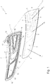
Figure 1 is a partially-exploded perspective view of an automotive light realized according to the teachings of the present invention; -
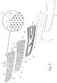
Figure 2 is an exploded perspective view of the backlighting system of the automotive light shown inFigure 1 , with parts in transparency and parts removed for clarity; -
Figure 3 is a sectional view of a portion of the automotive light shown inFigures 1 and2 , with parts removed for clarity; -
Figures 4 and 5 are two diagrams of the light intensity of a light beam emitted by the automotive light shown inFigure 1 ; whereas -
Figure 6 is a sectional view of a portion of a second embodiment of the automotive light shown inFigures 1 and2 , with parts removed for clarity. - With reference to
Figures 1 ,2 and3 ,number 1 denotes as a whole an automotive light, i.e. a lighting device particularly adapted to be located on the front part or rear part of a motor-vehicle bodywork, with the function of emitting light signals suitable for signalling the position of the vehicle and/or the sudden deceleration of the vehicle and/or the turning direction of the vehicle while driving. - In other words, the
automotive light 1 is adapted to be attached to the front or rear part of the bodywork of a car, van, truck, motorcycle or other similar motor vehicle, to perform the function of a headlight or taillight. - In the example shown, in particular, the
automotive light 1 is preferably structured to be stably recessed into the rear part of the bodywork of a car or other similar motor vehicle. - In other words, the
automotive light 1 is a taillight for cars and the like. - Obviously, in a different embodiment the
automotive light 1 could also be structured to be simply fixed protruding from the rear part of the vehicle bodywork (not shown). - With reference to
Figures 1 ,2 and3 , theautomotive light 1 firstly comprises: a substantially rigid and preferably made of plastic material,rear casing 2 which is substantially basin-shaped and is preferably structured so as to be at least partially recessed into a seat specially made in the rear part of the vehicle bodywork (not shown); and a substantially rigid and preferably made of a plastic material, front half-shell 3 which is arranged to close the mouth of therear casing 2, preferably so as to be able to surface outside the vehicle bodywork, and is provided with one or more transparent or semi-transparent areas. - Obviously, in a different embodiment the
rear casing 2 could also be structured to be simply cantilever fixed to the rear part of the vehicle bodywork (not shown). - In more detail, in the example shown the
rear casing 2 is preferably made of an opaque plastic material, preferably via an injection moulding process. The front half-shell 3, on the other hand, is preferably made of a transparent or semi-transparent plastic material, such as for example polycarbonate or polymethyl-methacrylate, also in this case preferably via an injection moulding process. - With reference to
Figures 1 ,2 and3 , in addition, theautomotive light 1 is moreover provided with at least one electrically-poweredlighting assembly 4 that emits light on command, and is located inside therear casing 2, beneath at least one of the transparent or semi-transparent areas of the front half-shell 3, so as to be able to selectively backlight the same transparent or semi-transparent area of the front half-shell 3. - In more detail, each transparent or semi-transparent area of front half-
shell 3 is provided with/divided into one or more adjacent transparent or semi-transparent sectors, each of which is preferably exclusively associated with a specific light signal. - The
lighting assembly 4, in turn, is specifically designed to selectively backlight the transparent or semi-transparent sectors of the front half-shell 3, separately and independently from one another, so that the light beams coming out from theautomotive light 1 through the various transparent or semi-transparent sectors of front half-shell 3, comply with the approval specifications for position and/or stop and/or turn signals of the vehicle. - In the example shown, in particular, the front half-
shell 3 is preferably provided with two adjacent transparent or semi-transparent areas. - The first transparent or semi-transparent area of front half-
shell 3 is preferably provided with a single large transparent orsemi-transparent sector 5. The second transparent or semi-transparent area of front half-shell 3, on the other hand, is preferably provided with a plurality of transparent or semi-transparent sectors 6 (two sectors in the example shown). -
Lighting assembly 4, in turn, is preferably located inside therear casing 2, beneath both transparent or semi-transparent areas of front half-shell 3, and is selectively adapted to backlight the transparent orsemi-transparent sectors shell 3, separately and independently to one another. - With reference to
Figures 2 and3 , thelighting assembly 4 comprises: an electrically-poweredplatelike light source 10 that emits light on command and is located inside therear casing 2 so as to be able to simultaneously backlight all transparent orsemi-transparent sectors shell 3; a substantially platelike LCD panel 11 (acronym of Liquid Crystal Display) that extends inside therear casing 2 in front of the transparent or semi-transparent area(s) of the front half-shell 3 to be backlighted, preferably substantially for the whole extension of the transparent or semi-transparent area(s) of the front half-shell 3 to be backlighted, so as to be crossed by the light emitted by theplatelike light source 10 and directed towards the front half-shell 3; and anelectronic control unit 12 which is located inside therear casing 2, preferably behind theplatelike light source 10, and is adapted to drive theLCD panel 11 so as to control the passing of the light through the single pixels of theLCD panel 11. - In more detail, the
LCD panel 11 extends inside torear casing 2 preferably while remaining more or less skimmed over the inner face of the front half-shell 3, and is divided into a multitude of small-size sectors or pixels, preferably arranged in a matrix configuration, each of which is capable of, selectively and alternatively, allowing or preventing the light to pass through the same pixel. - In other words, each pixel of
LCD panel 11 can be, selectively and alternatively, transparent or opaque to the light coming from the beneath-locatedplatelike light source 10. - In the example shown, in addition, the
LCD panel 11 is preferably substantially complementary in shape to the rear face of front half-shell 3. - The
electronic control unit 12, in turn, is adapted to control the transparent or opaque state of the single pixels ofLCD panel 11, so that theplatelike light source 10 can/ succeed in backlight only some specific areas of the front half-shell 3 whose shape and dimensions is determined by the number and position of the transparent pixels of theLCD panel 11. - In more detail,
electronic control unit 12 is adapted to control the transparent or opaque state of the single pixels ofLCD panel 11, so that theplatelike light source 10 can selectively backlight each transparent orsemi-transparent sector shell 3, or part of the same transparent orsemi-transparent sector semi-transparent sectors - Preferably,
electronic control unit 12 is furthermore adapted to also drive theplatelike light source 10. - In more detail, the
electronic control unit 12 is preferably adapted to activate theplatelike light source 10 only when one or more pixels of theLCD panel 11 are configured so as to be transparent to the light coming from the sameplatelike light source 10. - With reference to
Figures 2 and3 , moreover thelighting assembly 4 preferably also comprises amultidirectional collimation device 13 which is located inside therear casing 2, between theplatelike light source 10 and theLCD panel 11, and is adapted to collimate the light emitted by theplatelike light source 10 in a plurality of main emission directions d0 suitably angled to one another and each of which is uniquely associated with a respective transparent orsemi-transparent sector shell 3. - In more detail, the
collimation device 13 is adapted to collimate the light emitted from theplatelike light source 10 in a plurality of different predetermined directions, so that the light beam emitted from each transparent orsemi-transparent sector - In other words, the
collimation device 13 is adapted to collimate the light emitted from theplatelike light source 10 so as to form different light beams which, once crossing the corresponding transparent orsemi-transparent sectors figure 5 ) required by the approval regulations in force for light signals associated to the single transparent orsemi-transparent sectors - In even more detail, with reference to
Figures 4 and 5 , thecollimation device 13 is adapted to collimate the light emitted fromplatelike light source 10 in a series of predetermined and suitably angled directions, so that the light intensity of the light beam coming out from each transparent orsemi-transparent sector - Obviously the main emission direction d0 associated to each transparent or
semi-transparent sector shell 3 is inclined of a given angle with respect to the optical axis A of the automotive light. Optical axis that, in use, is substantially parallel to the longitudinal axis of the vehicle (not shown) that accommodates the sameautomotive light 1. - In other words, the
multidirectional collimation device 13 is adapted to collimate the light coming from theplatelike light source 10 in a series of predetermined and suitably angled directions, so that the light beam emitted from each transparent orsemi-transparent sector shell 3 meets the automotive standards for the position, stop or turn light signal specifically associated to the same transparent orsemi-transparent sector - With reference to
Figures 1 ,2 and3 , in the example shown, in particular, theplatelike light source 10 preferably comprises a multitude of LEDs 14 (acronym for Light Emitting Diode) or other electrically-powered point light sources, which are suitably distributed beneath the transparent or semi-transparent area(s) of the front half-shell 3 to be backlighted, so as to direct the emitted light towards the same transparent or semi-transparent area(s) of the front half-shell 3. - In more detail, the
LEDs 14 ofplatelike light source 10 are preferably spread on the front face of one ormore support boards 15 that are located inside therear casing 2, facing the transparent or semi-transparent area(s) of front half-shell 3 to be backlighted, so that thesingle LEDs 14 can direct the emitted light towards the front half-shell 3. Preferably, theLEDs 14 are moreover substantially uniformly spread underneath the transparent or semi-transparent area(s) of front half-shell 3 to be backlighted. - The
electronic control unit 12, in turn, is preferably adapted to control the switching on and off of theLEDs 14. - In more detail,
electronic control unit 12 is preferably programmed/configured to turn on only theLEDs 14 beneath the zone(s) ofLCD panel 11 that are momentarily transparent to light. - Preferably, the
single LEDs 14 ofplatelike light source 10 are finally RGB LEDs capable of varying, on command, the colour of the emitted light. - The
electronic control unit 12, in turn, is preferably adapted to drive thesingle RGB LEDs 14 so as to vary/control the colour of the light emitted by the single areas of theplatelike light source 10 towards the facing transparent orsemi-transparent sectors shell 3. - In the example shown, furthermore at least one and preferably each pixel of the
LCD panel 11 is preferably divided into three or more adjacent subpixels, which are able to allow or prevent the passing of the light independently to each other, and are provided with coloured filters having different colours from one another (typically the colours are red, green and blue). By appropriately varying the amount of light passing through each coloured subpixel, it is therefore possible to give/provide a specific colour hue/shade to the light that passes through the pixel ofLCD panel 11. -
Electronic control unit 12, in turn, is preferably configured so as to control the transparent or opaque state of the single subpixels ofLCD panel 11, in such a way to control/vary the hue/shade of the colour of the light passing through the pixel ofLCD panel 11 and reaches the facing transparent orsemi-transparent sector shell 3. - Preferably, the
LCD panel 11 finally has a TFT architecture (acronym of Thin Film Transistor). - Being an optoelectronic device widely known and easily available on the market, the
LCD panel 11 won't be further described. - With reference to
Figures 2 and3 , themultidirectional collimation device 13 preferably comprises a series of basic collimator members, each located at arespective LED 14 or point light source, and are structured to collimate the light rays emitted from thesame LED 14 each in a respective predetermined direction dc not necessarily orthogonal to the immediately facing area of front half-shell 3. - The collimation direction dc of the single basic collimator members are furthermore selected to form a series of light beams that are directed each towards a respective transparent or
semi-transparent sector shell 3, and have, on coming out from the same transparent orsemi-transparent sector - In more detail, the
collimation device 13 preferably comprises a series oflenticular bodies 16 that are located each in front of arespective LED 14, and are structured to collimate the light rays emitted from thesame LED 14 each in a respective predetermined direction dc not necessarily orthogonal to the immediately facing area of front half-shell 3. - Preferably furthermore the
multidirectional collimation device 13 also comprises a transparent or semi-transparent supportingplate 17, preferably made of plastic material, that extends inside therear casing 2, more or less skimmed over and optionally also parallel toLCD panel 11, substantially for the whole extent of theLCD panel 11 and/or of the transparent or semi-transparent area(s) of front half-shell 3 to be backlighted. Thelenticular bodies 16 are preferably located on the rear face of supportingplate 17. - In the example shown, in particular, the
lenticular bodies 16 are preferably made in one piece with the supportingplate 17. - With reference to
Figures 1 ,2 and3 , preferably thelighting assembly 4 moreover comprises aspacer mask 18 with a platelike structure and preferably made of opaque plastic material, which is interposed between the platelikelight source 10, or rather the supportingplate 17 of platelikelight source 10, and theLCD panel 11, and is provided with a series of pass-throughopenings 19 each of which is aligned with a respective transparent orsemi-transparent sector shell 3, and preferably also substantially copies the shape of the immediately-superjacent transparent orsemi-transparent sector - Operation of
automotive light 1 is easily inferable from the above and does not require further explanations. - As regards
lighting assembly 4,LCD panel 11 allows to selectively and separately backlight each transparent orsemi-transparent sector shell 3 using a single/sole light source. - In addition, the
LCD panel 11 allows to dynamically backlight even a single part of the transparent orsemi-transparent sector - In more detail, the
electronic control unit 12 can, for example, drive theLCD panel 11 so as to backlight a part of any transparent orsemi-transparent sector shell 3 that progressively grows in its extension over time, or that moves inside the transparent orsemi-transparent sector - Finally, the use of
RGB LEDs 14 in combination with anLCD panel 11 with coloured subpixels, enables thelighting assembly 4 to produce light beams with a wider range of colours than those obtainable from traditional backlighting systems, and even capable of reaching the chromatic shades required for the light signals of automotive lights. - The advantages associated with the particular structure of the
lighting assembly 4 are considerable. - Firstly, the
multidirectional collimation device 13 enables thelighting assembly 4 to produce light beams that satisfy the emission requirement for light signals generated by automotive lights. - The backlighting systems that are traditionally coupled to LCD panels to produce common displays and the like, in fact, basically comprise a LED matrix and a platelike diffusing screen which is interposed between the LED matrix and the LCD panel, and is structured to scatter the light produced by the LED matrix evenly over the entire extension of the LCD panel.
- Conventional backlighting systems, therefore, are physically unable to produce many light beams, each of which has a prevailing component parallel to a predetermined direction (i.e. the main emission direction d0) and a substantially Gaussian distribution of the light intensity around this predetermined direction.
- In addition, the traditional white-light backlight systems do not allow the production of light beams that meet the colorimetric requirements (gradation and/or colour intensity) required by the approval specifications for automotive lights.
- The
multidirectional collimation device 13 in combination with the platelikelight source 10 additionally allows to considerably reduce the thickness of the automotive light, with all the advantages that this entails. - It is finally clear that modifications and variations cab be made to the
automotive light 1 described above without however departing from the scope of the present invention. - For example, with reference to
Figure 6 , in a different embodiment ofmultidirectional collimation device 13, the basic collimator members are a series of cup-shapedreflector bodies 26 preferably made of plastic material, that are fitted each onto arespective LED 14 of platelikelight source 10 so as to surround thesame LED 14, and have a substantially parabolic profile so as to collimate the light rays emitted from thesame LED 14 in a predetermined direction dc not necessarily orthogonal to the immediately-facing area of front half-shell 3. - Preferably, reflector cup-shaped
bodies 26 are moreover attached to the rear face of a transparent or semi-transparent supportingplate 27, preferably made of plastic material, which extends insiderear casing 2, more or less skimmed over and optionally also parallel to theLCD panel 11, substantially for the whole extent of theLCD panel 11 and/or of the transparent or semi-transparent areas of front half-shell 3 to be backlighted. - In a more sophisticated embodiment, furthermore, the
LCD panel 11 can be at least partially embedded/incorporated in the front half-shell 3. - Finally, in a non-shown embodiment, instead of being backlighted by
lighting assembly 4, the first transparent or semi-transparent area of front half-shell 3, and therefore its transparent orsemi-transparent sector 5, may be backlighted by a second electrically-powered lighting assembly completely separated fromlighting assembly 4. - This second lighting assembly, in particular, may comprise: a light-guide plate that is made of photoconductive material, and extends skimmed over the inner surface of front half-
shell 3, immediately beneath the transparent orsemi-transparent sector 5, so as to cover the whole area of the transparent orsemi-transparent sector 5; and a series of LEDs (acronym for Light Emitting Diode) that are placed in abutment against one or more sides of the light-guide plate so as to direct the light inside the body of the light-guide plate. The light then travels within the body of the light-guide plate by total internal reflection and comes out in known manner from the front face of the light-guide plate directed towards the superjacent transparent orsemi-transparent sector 5 of front half-shell 3.
Claims (15)
- An automotive light (1) comprising: a substantially basin-shaped, rear casing (2); a front half-shell (3) which is arranged to close the mouth of the rear casing (2) and is provided with a plurality of transparent or semi-transparent sectors (5, 6); and at least one lighting assembly (4) that emits light on command, and is located inside the rear casing (2) so as to selectively backlight said transparent or semi-transparent sectors (5, 6) of the front half-shell (3);
the automotive light (1) being characterised in that the lighting assembly (4) comprises: an electrically-powered platelike light source (10) which emits light on command and is placed inside the rear casing (2) to contemporaneously backlight said transparent or semi-transparent sectors (5, 6) of the front half-shell (3); an LCD panel (11) that extends inside the rear casing (2), in front of the transparent or semi-transparent sectors (5, 6) of the front half-shell (3), so as to be crossed by the light emitted by the platelike light source (10) and directed towards the front half-shell (3); and an electronic control unit (12) which is adapted to drive the LCD panel (11) in order to control the passing of the light through the single pixels of the LCD panel (11) so that the platelike light source (10) can selectively backlight each transparent or semi-transparent sector (5, 6) of the front half-shell (3), or part of the same transparent or semi-transparent sector (5, 6), separately and independently from the other transparent or semi-transparent sectors (5, 6). - Automotive light according to Claim 1, wherein the lighting assembly (4) also comprises a multidirectional collimation device (13) which is placed inside the rear casing (2), between the platelike light source (10) and the LCD panel (11), and is adapted to collimate the light emitted by the platelike light source (10) into a plurality of main emission directions (d0) suitably angled to one another and each of which is uniquely associated to a respective transparent or semi-transparent sector (5, 6) of the front half-shell (3).
- Automotive light according to Claim 2, wherein the multidirectional collimation device (13) is adapted to collimate the light emitted from the platelike light source (10) so that the light beam coming out from each transparent or semi-transparent sector (5, 6) of the front half-shell (3) has a prevailing component parallel to the corresponding main emission direction (d0), and a predetermined angular distribution of the light around said main emission direction (do) .
- Automotive light according to Claim 3, wherein the multidirectional collimation device (13) is adapted to collimate the light coming out from the platelike light source (10) so that the light intensity of the light beam exiting each transparent or semi-transparent sector (5, 6) has a substantially bell-shaped angular distribution around the main emission direction (d0) with the maximum intensity on the main emission direction (d0).
- Automotive light according to any one of the preceding claims, wherein the electronic control unit (12) is moreover adapted to drive the platelike light source (10), so as to activate the platelike light source (10) only when one or more pixels of the LCD panel (11) are transparent to the light coming from the platelike light source (10).
- Automotive light according to any one of the preceding claims, in which the platelike light source (10) comprises a multitude of LEDs (14) which are distributed substantially uniformly beneath the areas of the front half-shell (3) to be backlighted.
- Automotive light according to Claim 6, wherein the multidirectional collimation device (13) comprises a series of basic collimator members (16, 26) that are located each at a respective LED (14), and are structured to collimate the light rays coming out of the same LED (14) each in a respective predetermined direction (dc).
- Automotive light according to Claim 7, wherein the basic collimator members are lenticular bodies (16) placed each in front of a respective LED (14) of the platelike light source (10).
- Automotive light according to Claim 7, wherein the basic collimator members are cup-shaped reflector bodies (26) fitted each onto a respective LED (14) of the platelike light source (10).
- Automotive light according to Claim 8 or 9, in which the basic collimator members (16, 26) are located on the rear face of a transparent or semi-transparent supporting plate (17, 27) that extends inside the rear casing (2), skimmed over the LCD panel (11).
- Automotive light according to any one of Claims 6 to 10, wherein the electronic control unit (12) is adapted to control the switching on and off of the LEDs (14) so as to turn on solely the LEDs (14) beneath the areas of the LCD panel (11) that are momentarily transparent to light.
- Automotive light according to any one of Claims 6 to 11, wherein the LEDs (14) are RGB LEDs capable of varying, on command, the colour of the emitted light; the electronic control unit (12) being adapted to drive the single RGB LEDs (14) so as to vary the colour of the light emitted by the single areas of the platelike light source (10).
- Automotive light according to Claim 12, wherein the single pixels of the LCD panel (11) are divided into three or more adjacent subpixels, which are able to allow or prevent the light to pass through independently to one another, and are provided with coloured filters having different colour to one another; the electronic control unit (12) being adapted to control the transparent or opaque state of the single subpixels so as to vary the hue/shade of the colour of the light that pass through the same pixel of the LCD panel (11).
- Automotive light according to any one of the preceding claims, wherein the LCD panel (11) has a TFT architecture.
- Automotive light according to any one of the preceding claims, wherein the lighting assembly (4) additionally comprises a platelike spacer mask (18) which is interposed between the platelike light source (10) and the LCD panel (11), and is provided with a series of pass-through openings (19) each of which is aligned with a respective transparent or semi-transparent sector (5, 6) of the front half-shell (3).
Priority Applications (1)
| Application Number | Priority Date | Filing Date | Title |
|---|---|---|---|
| EP18425047.0A EP3597991B1 (en) | 2018-06-21 | 2018-06-21 | Automotive light |
Applications Claiming Priority (1)
| Application Number | Priority Date | Filing Date | Title |
|---|---|---|---|
| EP18425047.0A EP3597991B1 (en) | 2018-06-21 | 2018-06-21 | Automotive light |
Publications (3)
| Publication Number | Publication Date |
|---|---|
| EP3597991A1 true EP3597991A1 (en) | 2020-01-22 |
| EP3597991A8 EP3597991A8 (en) | 2020-04-15 |
| EP3597991B1 EP3597991B1 (en) | 2025-05-21 |
Family
ID=63350487
Family Applications (1)
| Application Number | Title | Priority Date | Filing Date |
|---|---|---|---|
| EP18425047.0A Active EP3597991B1 (en) | 2018-06-21 | 2018-06-21 | Automotive light |
Country Status (1)
| Country | Link |
|---|---|
| EP (1) | EP3597991B1 (en) |
Cited By (4)
| Publication number | Priority date | Publication date | Assignee | Title |
|---|---|---|---|---|
| EP3945242A1 (en) * | 2020-07-29 | 2022-02-02 | Hyundai Mobis Co., Ltd. | Head lamp for vehicle |
| DE102021122264A1 (en) | 2021-08-27 | 2023-03-02 | HELLA GmbH & Co. KGaA | Lighting device for a vehicle |
| WO2024003140A1 (en) * | 2022-06-30 | 2024-01-04 | Valeo Vision | Lighting and signalling device for a motor vehicle |
| EP4198383A4 (en) * | 2020-08-11 | 2024-09-25 | LG Innotek Co., Ltd. | Lighting apparatus and vehicle having same |
Citations (8)
| Publication number | Priority date | Publication date | Assignee | Title |
|---|---|---|---|---|
| US5361190A (en) * | 1990-02-20 | 1994-11-01 | K. W. Muth Co. Inc. | Mirror assembly |
| US20030081153A1 (en) * | 2001-10-26 | 2003-05-01 | Keiji Kobayashi | Lens array substrate and liquid crystal display apparatus |
| DE10233719A1 (en) * | 2002-07-24 | 2004-02-05 | Bayerische Motoren Werke Ag | Light, especially for motor vehicle has light source(s), cover in light radiation direction with electrical diffuser whose optical action can be varied to produce multiple functionality of light |
| DE102011076330A1 (en) * | 2011-05-24 | 2012-11-29 | Osram Ag | Exterior lighting unit e.g. brake light of motor vehicle e.g. passenger car, has light-generating unit that is equipped with screen formed with several controllable pixels arranged in matrix form |
| US20150036373A1 (en) * | 2013-08-02 | 2015-02-05 | Hon Hai Precision Industry Co., Ltd. | Led vehicle headlamp with electrochromic device |
| DE102013223717A1 (en) * | 2013-11-20 | 2015-05-21 | Automotive Lighting Reutlingen Gmbh | Automotive lighting device |
| EP2980866A1 (en) * | 2013-03-25 | 2016-02-03 | LG Innotek Co., Ltd. | Light-emitting element package |
| US20160039333A1 (en) * | 2014-08-06 | 2016-02-11 | Young Optics Inc. | Vehicle lighting system and method of fabrication |
Family Cites Families (3)
| Publication number | Priority date | Publication date | Assignee | Title |
|---|---|---|---|---|
| US20060250809A1 (en) * | 2001-05-25 | 2006-11-09 | Michael Strazzanti | Vehicle lamp apparatus |
| KR20080036190A (en) * | 2005-07-08 | 2008-04-25 | 코닌클리즈케 필립스 일렉트로닉스 엔.브이. | Light modules that produce light with electrically changeable scattering patterns and their use as multipurpose lights |
| DE102012004759A1 (en) * | 2012-03-08 | 2013-09-12 | GM Global Technology Operations LLC (n.d. Ges. d. Staates Delaware) | Tail lamp arrangement of motor car, has display surface portion that is arranged with several distributed luminous elements for forming and independently controlling different light patterns |
-
2018
- 2018-06-21 EP EP18425047.0A patent/EP3597991B1/en active Active
Patent Citations (8)
| Publication number | Priority date | Publication date | Assignee | Title |
|---|---|---|---|---|
| US5361190A (en) * | 1990-02-20 | 1994-11-01 | K. W. Muth Co. Inc. | Mirror assembly |
| US20030081153A1 (en) * | 2001-10-26 | 2003-05-01 | Keiji Kobayashi | Lens array substrate and liquid crystal display apparatus |
| DE10233719A1 (en) * | 2002-07-24 | 2004-02-05 | Bayerische Motoren Werke Ag | Light, especially for motor vehicle has light source(s), cover in light radiation direction with electrical diffuser whose optical action can be varied to produce multiple functionality of light |
| DE102011076330A1 (en) * | 2011-05-24 | 2012-11-29 | Osram Ag | Exterior lighting unit e.g. brake light of motor vehicle e.g. passenger car, has light-generating unit that is equipped with screen formed with several controllable pixels arranged in matrix form |
| EP2980866A1 (en) * | 2013-03-25 | 2016-02-03 | LG Innotek Co., Ltd. | Light-emitting element package |
| US20150036373A1 (en) * | 2013-08-02 | 2015-02-05 | Hon Hai Precision Industry Co., Ltd. | Led vehicle headlamp with electrochromic device |
| DE102013223717A1 (en) * | 2013-11-20 | 2015-05-21 | Automotive Lighting Reutlingen Gmbh | Automotive lighting device |
| US20160039333A1 (en) * | 2014-08-06 | 2016-02-11 | Young Optics Inc. | Vehicle lighting system and method of fabrication |
Cited By (7)
| Publication number | Priority date | Publication date | Assignee | Title |
|---|---|---|---|---|
| EP3945242A1 (en) * | 2020-07-29 | 2022-02-02 | Hyundai Mobis Co., Ltd. | Head lamp for vehicle |
| US11378249B2 (en) | 2020-07-29 | 2022-07-05 | Hyundai Mobis Co., Ltd. | Head lamp for vehicle |
| EP4198383A4 (en) * | 2020-08-11 | 2024-09-25 | LG Innotek Co., Ltd. | Lighting apparatus and vehicle having same |
| US12259625B2 (en) | 2020-08-11 | 2025-03-25 | Lg Innotek Co., Ltd. | Lighting device and vehicle lamp having same |
| DE102021122264A1 (en) | 2021-08-27 | 2023-03-02 | HELLA GmbH & Co. KGaA | Lighting device for a vehicle |
| WO2024003140A1 (en) * | 2022-06-30 | 2024-01-04 | Valeo Vision | Lighting and signalling device for a motor vehicle |
| FR3137437A1 (en) * | 2022-06-30 | 2024-01-05 | Valeo Vision | Lighting and signaling device for a motor vehicle. |
Also Published As
| Publication number | Publication date |
|---|---|
| EP3597991B1 (en) | 2025-05-21 |
| EP3597991A8 (en) | 2020-04-15 |
Similar Documents
| Publication | Publication Date | Title |
|---|---|---|
| EP3597991B1 (en) | Automotive light | |
| US12429188B2 (en) | Illumination apparatus for a motor vehicle | |
| EP3597987A1 (en) | Automotive light | |
| US20120002442A1 (en) | Display device for a vehicle and method for producing the display device | |
| US12276389B2 (en) | Illumination device for a motor vehicle | |
| US11186221B2 (en) | Work vehicle with rear pillar lamp | |
| US7252418B2 (en) | Lights for motor vehicles | |
| EP3671019B1 (en) | Vehicle lighting and/or signalling device | |
| CN108775547B (en) | Lighting display device | |
| JP6609135B2 (en) | Rear combination lamp for vehicles | |
| US11237318B1 (en) | Light for a motor vehicle | |
| EP3908481B1 (en) | Covering device, body part and motor vehicle | |
| US11760253B2 (en) | Lighting device for a motor vehicle | |
| CN112539392B (en) | Automobile headlamp system and automobile lamp | |
| US20190323674A1 (en) | Illumination device for vehicle, lighting tool for vehicle, window panel attached with lighting tool for vehicle, and on-vehicle display | |
| US20230099347A1 (en) | Lighting device | |
| JP5297560B2 (en) | Automotive lighting equipment | |
| US8232492B1 (en) | Electronically balanced illuminated panel | |
| US10690313B2 (en) | Automotive lighting unit | |
| CN109386813B (en) | Display device for vehicle | |
| WO2019186313A1 (en) | Electrical device for a vehicle running board | |
| CN117287660A (en) | Car Light | |
| CN112268263A (en) | Dynamic luminous tail lamp of automobile | |
| EP4023935B1 (en) | Automotive light | |
| JP7139140B2 (en) | Vehicle lighting device, vehicle lamp, window panel with vehicle lamp, in-vehicle display |
Legal Events
| Date | Code | Title | Description |
|---|---|---|---|
| PUAI | Public reference made under article 153(3) epc to a published international application that has entered the european phase |
Free format text: ORIGINAL CODE: 0009012 |
|
| STAA | Information on the status of an ep patent application or granted ep patent |
Free format text: STATUS: THE APPLICATION HAS BEEN PUBLISHED |
|
| AK | Designated contracting states |
Kind code of ref document: A1 Designated state(s): AL AT BE BG CH CY CZ DE DK EE ES FI FR GB GR HR HU IE IS IT LI LT LU LV MC MK MT NL NO PL PT RO RS SE SI SK SM TR |
|
| AX | Request for extension of the european patent |
Extension state: BA ME |
|
| STAA | Information on the status of an ep patent application or granted ep patent |
Free format text: STATUS: REQUEST FOR EXAMINATION WAS MADE |
|
| 17P | Request for examination filed |
Effective date: 20200721 |
|
| RBV | Designated contracting states (corrected) |
Designated state(s): AL AT BE BG CH CY CZ DE DK EE ES FI FR GB GR HR HU IE IS IT LI LT LU LV MC MK MT NL NO PL PT RO RS SE SI SK SM TR |
|
| STAA | Information on the status of an ep patent application or granted ep patent |
Free format text: STATUS: EXAMINATION IS IN PROGRESS |
|
| 17Q | First examination report despatched |
Effective date: 20220714 |
|
| REG | Reference to a national code |
Ref country code: DE Ref legal event code: R079 Free format text: PREVIOUS MAIN CLASS: F21S0043500000 Ref country code: DE Ref legal event code: R079 Ref document number: 602018082073 Country of ref document: DE Free format text: PREVIOUS MAIN CLASS: F21S0043500000 Ipc: F21S0043140000 |
|
| GRAP | Despatch of communication of intention to grant a patent |
Free format text: ORIGINAL CODE: EPIDOSNIGR1 |
|
| STAA | Information on the status of an ep patent application or granted ep patent |
Free format text: STATUS: GRANT OF PATENT IS INTENDED |
|
| RIC1 | Information provided on ipc code assigned before grant |
Ipc: F21S 43/50 20180101ALI20241125BHEP Ipc: F21S 43/40 20180101ALI20241125BHEP Ipc: F21S 43/31 20180101ALI20241125BHEP Ipc: F21S 43/20 20180101ALI20241125BHEP Ipc: F21S 43/14 20180101AFI20241125BHEP |
|
| INTG | Intention to grant announced |
Effective date: 20241213 |
|
| GRAS | Grant fee paid |
Free format text: ORIGINAL CODE: EPIDOSNIGR3 |
|
| GRAA | (expected) grant |
Free format text: ORIGINAL CODE: 0009210 |
|
| STAA | Information on the status of an ep patent application or granted ep patent |
Free format text: STATUS: THE PATENT HAS BEEN GRANTED |
|
| RAP3 | Party data changed (applicant data changed or rights of an application transferred) |
Owner name: MARELLI AUTOMOTIVE LIGHTING ITALY S.P.A. |
|
| P01 | Opt-out of the competence of the unified patent court (upc) registered |
Free format text: CASE NUMBER: APP_15127/2025 Effective date: 20250327 |
|
| AK | Designated contracting states |
Kind code of ref document: B1 Designated state(s): AL AT BE BG CH CY CZ DE DK EE ES FI FR GB GR HR HU IE IS IT LI LT LU LV MC MK MT NL NO PL PT RO RS SE SI SK SM TR |
|
| REG | Reference to a national code |
Ref country code: GB Ref legal event code: FG4D |
|
| REG | Reference to a national code |
Ref country code: CH Ref legal event code: EP |
|
| REG | Reference to a national code |
Ref country code: DE Ref legal event code: R096 Ref document number: 602018082073 Country of ref document: DE |
|
| REG | Reference to a national code |
Ref country code: IE Ref legal event code: FG4D |
|
| REG | Reference to a national code |
Ref country code: NL Ref legal event code: MP Effective date: 20250521 |
|
| PG25 | Lapsed in a contracting state [announced via postgrant information from national office to epo] |
Ref country code: PT Free format text: LAPSE BECAUSE OF FAILURE TO SUBMIT A TRANSLATION OF THE DESCRIPTION OR TO PAY THE FEE WITHIN THE PRESCRIBED TIME-LIMIT Effective date: 20250922 Ref country code: FI Free format text: LAPSE BECAUSE OF FAILURE TO SUBMIT A TRANSLATION OF THE DESCRIPTION OR TO PAY THE FEE WITHIN THE PRESCRIBED TIME-LIMIT Effective date: 20250521 Ref country code: ES Free format text: LAPSE BECAUSE OF FAILURE TO SUBMIT A TRANSLATION OF THE DESCRIPTION OR TO PAY THE FEE WITHIN THE PRESCRIBED TIME-LIMIT Effective date: 20250521 |
|
| REG | Reference to a national code |
Ref country code: LT Ref legal event code: MG9D |
|
| PG25 | Lapsed in a contracting state [announced via postgrant information from national office to epo] |
Ref country code: NO Free format text: LAPSE BECAUSE OF FAILURE TO SUBMIT A TRANSLATION OF THE DESCRIPTION OR TO PAY THE FEE WITHIN THE PRESCRIBED TIME-LIMIT Effective date: 20250821 Ref country code: GR Free format text: LAPSE BECAUSE OF FAILURE TO SUBMIT A TRANSLATION OF THE DESCRIPTION OR TO PAY THE FEE WITHIN THE PRESCRIBED TIME-LIMIT Effective date: 20250822 |
|
| PG25 | Lapsed in a contracting state [announced via postgrant information from national office to epo] |
Ref country code: PL Free format text: LAPSE BECAUSE OF FAILURE TO SUBMIT A TRANSLATION OF THE DESCRIPTION OR TO PAY THE FEE WITHIN THE PRESCRIBED TIME-LIMIT Effective date: 20250521 Ref country code: NL Free format text: LAPSE BECAUSE OF FAILURE TO SUBMIT A TRANSLATION OF THE DESCRIPTION OR TO PAY THE FEE WITHIN THE PRESCRIBED TIME-LIMIT Effective date: 20250521 |
|
| PG25 | Lapsed in a contracting state [announced via postgrant information from national office to epo] |
Ref country code: BG Free format text: LAPSE BECAUSE OF FAILURE TO SUBMIT A TRANSLATION OF THE DESCRIPTION OR TO PAY THE FEE WITHIN THE PRESCRIBED TIME-LIMIT Effective date: 20250521 |
|
| PG25 | Lapsed in a contracting state [announced via postgrant information from national office to epo] |
Ref country code: HR Free format text: LAPSE BECAUSE OF FAILURE TO SUBMIT A TRANSLATION OF THE DESCRIPTION OR TO PAY THE FEE WITHIN THE PRESCRIBED TIME-LIMIT Effective date: 20250521 |
|
| PG25 | Lapsed in a contracting state [announced via postgrant information from national office to epo] |
Ref country code: RS Free format text: LAPSE BECAUSE OF FAILURE TO SUBMIT A TRANSLATION OF THE DESCRIPTION OR TO PAY THE FEE WITHIN THE PRESCRIBED TIME-LIMIT Effective date: 20250821 |
|
| PG25 | Lapsed in a contracting state [announced via postgrant information from national office to epo] |
Ref country code: IS Free format text: LAPSE BECAUSE OF FAILURE TO SUBMIT A TRANSLATION OF THE DESCRIPTION OR TO PAY THE FEE WITHIN THE PRESCRIBED TIME-LIMIT Effective date: 20250921 |
|
| PG25 | Lapsed in a contracting state [announced via postgrant information from national office to epo] |
Ref country code: LV Free format text: LAPSE BECAUSE OF FAILURE TO SUBMIT A TRANSLATION OF THE DESCRIPTION OR TO PAY THE FEE WITHIN THE PRESCRIBED TIME-LIMIT Effective date: 20250521 |
|
| REG | Reference to a national code |
Ref country code: AT Ref legal event code: MK05 Ref document number: 1797006 Country of ref document: AT Kind code of ref document: T Effective date: 20250521 |
|
| REG | Reference to a national code |
Ref country code: DE Ref legal event code: R119 Ref document number: 602018082073 Country of ref document: DE |
|
| PG25 | Lapsed in a contracting state [announced via postgrant information from national office to epo] |
Ref country code: AT Free format text: LAPSE BECAUSE OF FAILURE TO SUBMIT A TRANSLATION OF THE DESCRIPTION OR TO PAY THE FEE WITHIN THE PRESCRIBED TIME-LIMIT Effective date: 20250521 Ref country code: SM Free format text: LAPSE BECAUSE OF FAILURE TO SUBMIT A TRANSLATION OF THE DESCRIPTION OR TO PAY THE FEE WITHIN THE PRESCRIBED TIME-LIMIT Effective date: 20250521 Ref country code: DK Free format text: LAPSE BECAUSE OF FAILURE TO SUBMIT A TRANSLATION OF THE DESCRIPTION OR TO PAY THE FEE WITHIN THE PRESCRIBED TIME-LIMIT Effective date: 20250521 |
|
| PG25 | Lapsed in a contracting state [announced via postgrant information from national office to epo] |
Ref country code: CZ Free format text: LAPSE BECAUSE OF FAILURE TO SUBMIT A TRANSLATION OF THE DESCRIPTION OR TO PAY THE FEE WITHIN THE PRESCRIBED TIME-LIMIT Effective date: 20250521 |
|
| PG25 | Lapsed in a contracting state [announced via postgrant information from national office to epo] |
Ref country code: EE Free format text: LAPSE BECAUSE OF FAILURE TO SUBMIT A TRANSLATION OF THE DESCRIPTION OR TO PAY THE FEE WITHIN THE PRESCRIBED TIME-LIMIT Effective date: 20250521 |
|
| PG25 | Lapsed in a contracting state [announced via postgrant information from national office to epo] |
Ref country code: RO Free format text: LAPSE BECAUSE OF FAILURE TO SUBMIT A TRANSLATION OF THE DESCRIPTION OR TO PAY THE FEE WITHIN THE PRESCRIBED TIME-LIMIT Effective date: 20250521 Ref country code: SK Free format text: LAPSE BECAUSE OF FAILURE TO SUBMIT A TRANSLATION OF THE DESCRIPTION OR TO PAY THE FEE WITHIN THE PRESCRIBED TIME-LIMIT Effective date: 20250521 |
|
| REG | Reference to a national code |
Ref country code: CH Ref legal event code: H13 Free format text: ST27 STATUS EVENT CODE: U-0-0-H10-H13 (AS PROVIDED BY THE NATIONAL OFFICE) Effective date: 20260127 |
|
| PG25 | Lapsed in a contracting state [announced via postgrant information from national office to epo] |
Ref country code: LU Free format text: LAPSE BECAUSE OF NON-PAYMENT OF DUE FEES Effective date: 20250621 |
|
| PG25 | Lapsed in a contracting state [announced via postgrant information from national office to epo] |
Ref country code: MC Free format text: LAPSE BECAUSE OF FAILURE TO SUBMIT A TRANSLATION OF THE DESCRIPTION OR TO PAY THE FEE WITHIN THE PRESCRIBED TIME-LIMIT Effective date: 20250521 |
|
| REG | Reference to a national code |
Ref country code: BE Ref legal event code: MM Effective date: 20250630 |
|
| PLBE | No opposition filed within time limit |
Free format text: ORIGINAL CODE: 0009261 |
|
| STAA | Information on the status of an ep patent application or granted ep patent |
Free format text: STATUS: NO OPPOSITION FILED WITHIN TIME LIMIT |
|
| REG | Reference to a national code |
Ref country code: CH Ref legal event code: L10 Free format text: ST27 STATUS EVENT CODE: U-0-0-L10-L00 (AS PROVIDED BY THE NATIONAL OFFICE) Effective date: 20260402 |
|
| PG25 | Lapsed in a contracting state [announced via postgrant information from national office to epo] |
Ref country code: DE Free format text: LAPSE BECAUSE OF NON-PAYMENT OF DUE FEES Effective date: 20260101 Ref country code: IE Free format text: LAPSE BECAUSE OF NON-PAYMENT OF DUE FEES Effective date: 20250621 |
|
| PG25 | Lapsed in a contracting state [announced via postgrant information from national office to epo] |
Ref country code: BE Free format text: LAPSE BECAUSE OF NON-PAYMENT OF DUE FEES Effective date: 20250630 Ref country code: IT Free format text: LAPSE BECAUSE OF NON-PAYMENT OF DUE FEES Effective date: 20250621 |
|
| PG25 | Lapsed in a contracting state [announced via postgrant information from national office to epo] |
Ref country code: FR Free format text: LAPSE BECAUSE OF NON-PAYMENT OF DUE FEES Effective date: 20250721 |
|
| PG25 | Lapsed in a contracting state [announced via postgrant information from national office to epo] |
Ref country code: CH Free format text: LAPSE BECAUSE OF NON-PAYMENT OF DUE FEES Effective date: 20250630 |
|
| 26N | No opposition filed |
Effective date: 20260224 |
|
| GBPC | Gb: european patent ceased through non-payment of renewal fee |
Effective date: 20250821 |