EP3597971A1 - Valve assembly - Google Patents
Valve assembly Download PDFInfo
- Publication number
- EP3597971A1 EP3597971A1 EP18461576.3A EP18461576A EP3597971A1 EP 3597971 A1 EP3597971 A1 EP 3597971A1 EP 18461576 A EP18461576 A EP 18461576A EP 3597971 A1 EP3597971 A1 EP 3597971A1
- Authority
- EP
- European Patent Office
- Prior art keywords
- rupture
- frangible member
- valve assembly
- housing
- contact
- Prior art date
- Legal status (The legal status is an assumption and is not a legal conclusion. Google has not performed a legal analysis and makes no representation as to the accuracy of the status listed.)
- Granted
Links
Images

Classifications
-
- F—MECHANICAL ENGINEERING; LIGHTING; HEATING; WEAPONS; BLASTING
- F16—ENGINEERING ELEMENTS AND UNITS; GENERAL MEASURES FOR PRODUCING AND MAINTAINING EFFECTIVE FUNCTIONING OF MACHINES OR INSTALLATIONS; THERMAL INSULATION IN GENERAL
- F16K—VALVES; TAPS; COCKS; ACTUATING-FLOATS; DEVICES FOR VENTING OR AERATING
- F16K13/00—Other constructional types of cut-off apparatus; Arrangements for cutting-off
- F16K13/04—Other constructional types of cut-off apparatus; Arrangements for cutting-off with a breakable closure member
-
- B—PERFORMING OPERATIONS; TRANSPORTING
- B64—AIRCRAFT; AVIATION; COSMONAUTICS
- B64D—EQUIPMENT FOR FITTING IN OR TO AIRCRAFT; FLIGHT SUITS; PARACHUTES; ARRANGEMENT OR MOUNTING OF POWER PLANTS OR PROPULSION TRANSMISSIONS IN AIRCRAFT
- B64D25/00—Emergency apparatus or devices, not otherwise provided for
- B64D25/08—Ejecting or escaping means
- B64D25/14—Inflatable escape chutes
-
- F—MECHANICAL ENGINEERING; LIGHTING; HEATING; WEAPONS; BLASTING
- F16—ENGINEERING ELEMENTS AND UNITS; GENERAL MEASURES FOR PRODUCING AND MAINTAINING EFFECTIVE FUNCTIONING OF MACHINES OR INSTALLATIONS; THERMAL INSULATION IN GENERAL
- F16K—VALVES; TAPS; COCKS; ACTUATING-FLOATS; DEVICES FOR VENTING OR AERATING
- F16K17/00—Safety valves; Equalising valves, e.g. pressure relief valves
- F16K17/02—Safety valves; Equalising valves, e.g. pressure relief valves opening on surplus pressure on one side; closing on insufficient pressure on one side
- F16K17/14—Safety valves; Equalising valves, e.g. pressure relief valves opening on surplus pressure on one side; closing on insufficient pressure on one side with fracturing member
- F16K17/16—Safety valves; Equalising valves, e.g. pressure relief valves opening on surplus pressure on one side; closing on insufficient pressure on one side with fracturing member with fracturing diaphragm ; Rupture discs
-
- F—MECHANICAL ENGINEERING; LIGHTING; HEATING; WEAPONS; BLASTING
- F16—ENGINEERING ELEMENTS AND UNITS; GENERAL MEASURES FOR PRODUCING AND MAINTAINING EFFECTIVE FUNCTIONING OF MACHINES OR INSTALLATIONS; THERMAL INSULATION IN GENERAL
- F16K—VALVES; TAPS; COCKS; ACTUATING-FLOATS; DEVICES FOR VENTING OR AERATING
- F16K17/00—Safety valves; Equalising valves, e.g. pressure relief valves
- F16K17/40—Safety valves; Equalising valves, e.g. pressure relief valves with a fracturing member, e.g. fracturing diaphragm, glass, fusible joint
- F16K17/403—Safety valves; Equalising valves, e.g. pressure relief valves with a fracturing member, e.g. fracturing diaphragm, glass, fusible joint with a fracturing valve member
-
- F—MECHANICAL ENGINEERING; LIGHTING; HEATING; WEAPONS; BLASTING
- F16—ENGINEERING ELEMENTS AND UNITS; GENERAL MEASURES FOR PRODUCING AND MAINTAINING EFFECTIVE FUNCTIONING OF MACHINES OR INSTALLATIONS; THERMAL INSULATION IN GENERAL
- F16K—VALVES; TAPS; COCKS; ACTUATING-FLOATS; DEVICES FOR VENTING OR AERATING
- F16K31/00—Actuating devices; Operating means; Releasing devices
- F16K31/44—Mechanical actuating means
- F16K31/56—Mechanical actuating means without stable intermediate position, e.g. with snap action
-
- F—MECHANICAL ENGINEERING; LIGHTING; HEATING; WEAPONS; BLASTING
- F17—STORING OR DISTRIBUTING GASES OR LIQUIDS
- F17C—VESSELS FOR CONTAINING OR STORING COMPRESSED, LIQUEFIED OR SOLIDIFIED GASES; FIXED-CAPACITY GAS-HOLDERS; FILLING VESSELS WITH, OR DISCHARGING FROM VESSELS, COMPRESSED, LIQUEFIED, OR SOLIDIFIED GASES
- F17C2205/00—Vessel construction, in particular mounting arrangements, attachments or identifications means
- F17C2205/03—Fluid connections, filters, valves, closure means or other attachments
- F17C2205/0302—Fittings, valves, filters, or components in connection with the gas storage device
- F17C2205/0311—Closure means
- F17C2205/032—Closure means pierceable
-
- F—MECHANICAL ENGINEERING; LIGHTING; HEATING; WEAPONS; BLASTING
- F17—STORING OR DISTRIBUTING GASES OR LIQUIDS
- F17C—VESSELS FOR CONTAINING OR STORING COMPRESSED, LIQUEFIED OR SOLIDIFIED GASES; FIXED-CAPACITY GAS-HOLDERS; FILLING VESSELS WITH, OR DISCHARGING FROM VESSELS, COMPRESSED, LIQUEFIED, OR SOLIDIFIED GASES
- F17C2270/00—Applications
- F17C2270/07—Applications for household use
- F17C2270/0772—Inflation devices, e.g. for rescue vests or tyres
Definitions
- the present disclosure relates to valve assemblies and in particular, but not exclusively, to a valve assembly provided between a pressurized fluid source and an inflatable device to be inflated on release of the fluid from the source, e.g. for an inflatable escape slide in an aircraft or for an inflatable rescue raft on a ship or the like.
- Valves are used in many applications to allow/prevent or control the flow of fluid between a source and a destination.
- Valves are used, for example, in inflatable escape slides provided as emergency exits on aircraft.
- the escape slide is connected to a source e.g. a canister or cylinder of pressurised fluid.
- the valve is locked to prevent the fluid flowing from the cylinder into the slide or, indeed, escaping from the cylinder at all.
- the valve needs to be configured such that, in an emergency, it can be opened quickly and reliably, to automatically and immediately allow the inflation fluid to flow from the cylinder into the inflatable slide to activate and fully inflate the slide.
- Inflatable escape slides and the pressure vessel containing the pressurised fluid for inflation and its regulating valve mechanism are stored in a compartment adjacent a door of an aircraft in a stowed, deflated state.
- the emergency system When the door is closed, the emergency system is armed by means of a mechanical connection between the aircraft floor and the slide pack. To open the doors in a normal situation, the emergency system has to first be disarmed. In an emergency, or when evacuation is necessary, the deflated slide is deployed out of the door compartment. As the slide exits the aircraft, a trigger is actuated to open the valve to allow the fluid to flow to inflate the slide.
- Aircraft safety regulations for in-door evacuation slides require that the deployment and valve mechanism is purely mechanical, not relying on any electrical systems, and that the inflation is triggered by kinetic energy from the full weight of the slide falling out of the door.
- the valve should not, for example, be triggered by the pressure vessel being knocked or falling or some other impact on the vessel or some other, less than full deployment, movement of the slide.
- the valve mechanism also needs to be arranged such that regardless of the orientation of the slide package as it falls out of the door, the valve can be triggered.
- FIG. 1 shows an example of commonly used valve assemblies for evacuation slides as will be described further below. Valve assemblies are also disclosed in US 6,431,197 and US 4,269,386 .
- a problem with such assemblies is that they require several mechanical moving parts which result in more potential points of failure.
- the assemblies are also relatively bulky and heavy and complex and expensive to manufacture.
- valve assembly that is simple, lightweight, can be triggered from all angles and is reliable.
- valve assembly comprising:
- the frangible member comprises a disk or a membrane.
- the rupture means comprises a rod axially movable within the housing.
- the rod has a pointed end to rupture the frangible member.
- the biasing means comprises a spring in contact with the rupture means, biased to expand to bring the rupture means into contact with the frangible member.
- the bearing comprises two or more ball bearings mounted in a channel around the housing, the ball bearings extending into the housing to retain the biasing means in a non-biased state and the release means comprises a basket formed over a part of the housing and extending across at least part of the channel so as to hold the ball bearings in the state where they extend into the housing.
- the trigger comprises a wire or lanyard attached to the basket to lift the basket such that the ball bearings can move out of engagement with the biasing means so that the biasing means takes up its biased state.
- the ball bearings are attached to the basket.
- the trigger is fixed to the basket at a plurality of points.
- valve assemblies will be described by way of background.
- the assembly will be mainly described in relation to an aircraft evacuation slide, but such valve assemblies may find application in other areas, e.g. life rafts, off-shore emergency escape systems or, in fact, and inflatable objects.
- the valve assembly 10 is mounted, in use, to the pressurised vessel containing the pressurised fluid (not shown) via a port 1 in a valve housing 2.
- a fluid channel is formed through the valve between the port 1 and an outlet 3 that, in use, is fluidly connected to the evacuation slide or other inflatable object (not shown).
- the inflatable objected is stowed and deflated and the fluid channel is closed by the valve to prevent fluid flowing from the vessel to the slide/object.
- the fluid channel is closed by means of a valve rod 4 mounted in the housing.
- the rod 4 is axially moveable in the housing but in the closed or locked position an end 4a of the rod 4 sits in or across the port.
- the pressure inside the vessel, P V is greater than atmospheric pressure P A , which pushes an insert 12 upwards so as to seal side channels 11, thus preventing fluid flow into the fluid channel to the outlet 3.
- P A atmospheric pressure
- the rod 4 is held in this closed position, against the pressure of the fluid, by means of a lever 5 that is spring biased and secured in the closed position by a cam 6 that, in turn, is secured in position by a trigger in the form of a removable pin or lanyard 7.
- the lever 5, cam 6 and trigger are all mounted in a rotatable housing part 8, which is arranged to rotate relative to the rod 4. The rotation is necessary because the trigger 7 can only be pulled out in one direction but, as the evacuation slide is deployed and falls from the aircraft, it will tumble and take on different orientations - the housing part 8 will thus rotate so that the trigger can always be pulled out at the required angle.
- the aircraft door (not shown) is opened and the deflated slide is ejected out of the door compartment.
- the trigger lanyard 7 is attached to the slide such that as the slide falls out, the full weight of the slide pulling on the cam 6 causes the cam 6 to rotate and unlock the lever 5.
- the lever 5, under the bias of the lever spring 9, is then released thus, in turn, releasing the rod 4.
- the rod 4 is then moved axially (upwards in Fig 1A ). This causes a reduction in the pressure difference between P V and P A and fluid from the vessel can flow through the fluid channel this forcing the insert 12 down and opening the side channels 11. Fluid then flows from the vessel through the fluid channel and out of the outlet 3 into the slide to inflate the slide.
- a problem with such conventional systems is that they require a relatively large number of metal/mechanical components such as springs, cams, levers etc. This all adds more potential points of failure and adds to the bulk and weight of the assembly as well is its complexity and cost of manufacture.
- the present disclosure describes a so-called 'basket' valve assembly such as shown in the Figures.
- This comprises a housing 100 within which is defined a fluid channel 200 that is open at one end 200A for fluid connection to the pressure vessel (not shown).
- the fluid path is defined from the pressure vessel, through the fluid channel 200, out of the housing 100 via an outlet 300 to the slide or inflatable object (not shown).
- the flow path is closed by means of a disk or membrane 400 across the diameter of the fluid channel.
- this disk 400 is ruptured as described in more detail below, allowing fluid to flow from the pressure vessel to the slide via the fluid channel 200 and the outlet 300.
- a rod 500 is mounted in the housing extending into the fluid channel 200.
- a free end of the rod 500 is configured to rupture the disk 400 e.g. by piercing the disk when the rod 500 is brought into contact with the disk with sufficient force.
- the end of the rod 500 is pointed or sharpened like a needle 500A but other forms are also possible.
- the rod 500 is mounted, by its other end 500B to a spring biased piston component 600 mounted in a top part 100A of the valve assembly housing 100.
- a spring 700 secures the piston component 600 within the top part of the housing and, in normal conditions (deflated) is compressed.
- One or more bearings 800 are provided and positioned to retain the piston component, against the force of the spring 700, in the top part of the housing which ensures that the free end 500A of the rod 500 does not come into rupturing contact with the disk 400.
- the bearings are in the form of two or more balls provided in a recess below the top part of the housing and extending radially into the housing sufficient to act as a detent against the piston component and to prevent the spring 700 from expanding.
- the bearings 500 are secured in the detent configuration holding the piston component in position, by means of a basket 900 of preferably lightweight material having some flexibility.
- the basket 900 is fitted over the top part of the housing and extends across the bearings to secure them in the position where they act as a detent for the piston component.
- the basket may or may not be attached to the bearings.
- the basket 900 is, as mentioned above, preferably made of a lightweight material and can be made e.g. by 3D print/additive manufacture.
- the basket should fit around the top portion of the housing but does not need to be a complete cover and can have, as shown, spaces 900A in coverage which adds to the lightweight advantage.
- a trigger 1000 is attached to the basket and attaches the basket, in use, to the slide.
- the trigger is again preferably a lightweight component such as a light cable or wire or spring and its purpose is to pull the basket at least partially off from the top portion of the housing, as shown by the arrow A in Fig. 2C under the weight of the slide as it falls from the aircraft door on deployment.
- the attachment between the trigger and the slide and the valve assembly such be such that the full weight of the falling slide is at least sufficient to lift the basket so that it no longer covers the bearings 800 or, if attached to the bearings, that it lifts the bearings out of engagement with the piston component.
- the trigger has several points of attachment to the basket, with these being evenly spaced, so that the trigger force of the falling slide lifts the basket away from the bearings or lifts the basket and connected bearings away from contact with the piston component in a relatively equal and uniform manner.
- four points of contact are shown but other variations are of course possible.
- the deployed slide pulls on the trigger 1000 with enough force to lift the basket 900 so that it no longer extends over the bearings 800.
- the force of the spring 700 acting down on the piston component 600 is then sufficient to push the bearings radially outwards in the direction of arrow B so that they no longer retain the piston component in the top portion of the housing.
- the bias of the spring 700 then pushes the rod 500 down and the spring and rod are configured such that the free end 500A impacts against the disk 400 causing the disk to rupture. This then opens the fluid channel 200 and the pressurised fluid flows from the pressure vessel into the slide, inflating the slide.
- the bearings are mounted in the housing such that they can rotate relative to the housing - e.g. in a recess formed around the housing periphery. This also enables the basket to rotate relative to the housing. This rotation means that the valve can be reliably triggered regardless of the orientation of the assembly as the slide is deployed.
- the trigger Whilst deployment has been described in relation to an evacuation slide falling from a door of an aircraft, in other applications, the trigger can be activated by other movement or force provided it is sufficient to lift the basked so as to release the piston component.
- the described valve assembly provides a lightweight, simple, yet reliable solution to controlling fluid flow for inflation of an object from a pressurised fluid source.
- 3D printing the basket using composite materials a single piece of material can be used.
Landscapes
- Engineering & Computer Science (AREA)
- General Engineering & Computer Science (AREA)
- Mechanical Engineering (AREA)
- Business, Economics & Management (AREA)
- Emergency Management (AREA)
- Aviation & Aerospace Engineering (AREA)
- Safety Valves (AREA)
- Filling Or Discharging Of Gas Storage Vessels (AREA)
Abstract
Description
- The present disclosure relates to valve assemblies and in particular, but not exclusively, to a valve assembly provided between a pressurized fluid source and an inflatable device to be inflated on release of the fluid from the source, e.g. for an inflatable escape slide in an aircraft or for an inflatable rescue raft on a ship or the like.
- Valves are used in many applications to allow/prevent or control the flow of fluid between a source and a destination. Valves are used, for example, in inflatable escape slides provided as emergency exits on aircraft. The escape slide is connected to a source e.g. a canister or cylinder of pressurised fluid. Generally, the valve is locked to prevent the fluid flowing from the cylinder into the slide or, indeed, escaping from the cylinder at all. The valve needs to be configured such that, in an emergency, it can be opened quickly and reliably, to automatically and immediately allow the inflation fluid to flow from the cylinder into the inflatable slide to activate and fully inflate the slide.
- Inflatable escape slides and the pressure vessel containing the pressurised fluid for inflation and its regulating valve mechanism are stored in a compartment adjacent a door of an aircraft in a stowed, deflated state. When the door is closed, the emergency system is armed by means of a mechanical connection between the aircraft floor and the slide pack. To open the doors in a normal situation, the emergency system has to first be disarmed. In an emergency, or when evacuation is necessary, the deflated slide is deployed out of the door compartment. As the slide exits the aircraft, a trigger is actuated to open the valve to allow the fluid to flow to inflate the slide. Aircraft safety regulations for in-door evacuation slides require that the deployment and valve mechanism is purely mechanical, not relying on any electrical systems, and that the inflation is triggered by kinetic energy from the full weight of the slide falling out of the door. The valve should not, for example, be triggered by the pressure vessel being knocked or falling or some other impact on the vessel or some other, less than full deployment, movement of the slide.
- The valve mechanism also needs to be arranged such that regardless of the orientation of the slide package as it falls out of the door, the valve can be triggered.
-
Figure 1 shows an example of commonly used valve assemblies for evacuation slides as will be described further below. Valve assemblies are also disclosed inUS 6,431,197 andUS 4,269,386 . - A problem with such assemblies is that they require several mechanical moving parts which result in more potential points of failure. The assemblies are also relatively bulky and heavy and complex and expensive to manufacture.
- There is a need for a valve assembly that is simple, lightweight, can be triggered from all angles and is reliable.
- The present disclosure, in one aspect, provides a valve assembly comprising:
- a valve housing defining therein a fluid flow channel between a first end arranged to be connected to a source of pressurised fluid, and an outlet; a frangible member disposed within and across the fluid flow channel so as to block flow from the first end to the outlet;
- rupture means for rupturing the frangible member to allow flow from the first end to the outlet;
- biasing means for biasing the means for rupturing into contact with the frangible member to cause rupture thereof;
- retaining means for retaining the rupture means out of contact with the frangible member to prevent rupture thereof;
- release means configured to release the retaining means to allow the biasing means to bias the rupture means into contact with the frangible member;
- wherein the retaining means a bearing extending to engage the biasing means and hold it in a compressed state, against its bias; and securing means for securing the bearing in the engaged state,
- wherein the release means comprises a trigger (1000) attached to the securing means which, when actuated, moves the securing means to release the bearing away from engagement with the biasing means whereby the biasing means expands to bias the rupture means into contact with the frangible member to cause rupture thereof.
- Preferably, the frangible member comprises a disk or a membrane.
- Preferably, the rupture means comprises a rod axially movable within the housing.
- Preferably, the rod has a pointed end to rupture the frangible member.
- Preferably, the biasing means comprises a spring in contact with the rupture means, biased to expand to bring the rupture means into contact with the frangible member.
- Preferably, the bearing comprises two or more ball bearings mounted in a channel around the housing, the ball bearings extending into the housing to retain the biasing means in a non-biased state and the release means comprises a basket formed over a part of the housing and extending across at least part of the channel so as to hold the ball bearings in the state where they extend into the housing.
- Preferably, the trigger comprises a wire or lanyard attached to the basket to lift the basket such that the ball bearings can move out of engagement with the biasing means so that the biasing means takes up its biased state.
- Preferably, the ball bearings are attached to the basket.
- Preferably, the trigger is fixed to the basket at a plurality of points.
- Preferred embodiments will now be described by way of example only, with reference to the drawings.
-
-
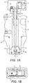
Figure 1A is a cross-sectional view of a conventional valve assembly. -
Figure 1B is a top view of the assembly ofFigure 1A . -
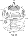
Figure 2A is a perspective view of a valve assembly according to the present disclosure. -
Figure 2B is a cut-away view of the top part of the assembly ofFigure 2A . -
Figure 2C is a detail fromFigure 2B . - Referring first to
Figures 1A and 1B a conventional valve assembly will be described by way of background. The assembly will be mainly described in relation to an aircraft evacuation slide, but such valve assemblies may find application in other areas, e.g. life rafts, off-shore emergency escape systems or, in fact, and inflatable objects. - The
valve assembly 10 is mounted, in use, to the pressurised vessel containing the pressurised fluid (not shown) via aport 1 in avalve housing 2. A fluid channel is formed through the valve between theport 1 and anoutlet 3 that, in use, is fluidly connected to the evacuation slide or other inflatable object (not shown). In normal circumstances, the inflatable objected is stowed and deflated and the fluid channel is closed by the valve to prevent fluid flowing from the vessel to the slide/object. In the example shown, the fluid channel is closed by means of avalve rod 4 mounted in the housing. Therod 4 is axially moveable in the housing but in the closed or locked position anend 4a of therod 4 sits in or across the port. Generally, the pressure inside the vessel, PV, is greater than atmospheric pressure PA, which pushes aninsert 12 upwards so as to sealside channels 11, thus preventing fluid flow into the fluid channel to theoutlet 3. Therod 4 is held in this closed position, against the pressure of the fluid, by means of alever 5 that is spring biased and secured in the closed position by acam 6 that, in turn, is secured in position by a trigger in the form of a removable pin orlanyard 7. Thelever 5,cam 6 and trigger are all mounted in arotatable housing part 8, which is arranged to rotate relative to therod 4. The rotation is necessary because thetrigger 7 can only be pulled out in one direction but, as the evacuation slide is deployed and falls from the aircraft, it will tumble and take on different orientations - thehousing part 8 will thus rotate so that the trigger can always be pulled out at the required angle. - In the event of evacuation being required, the aircraft door (not shown) is opened and the deflated slide is ejected out of the door compartment. The
trigger lanyard 7 is attached to the slide such that as the slide falls out, the full weight of the slide pulling on thecam 6 causes thecam 6 to rotate and unlock thelever 5. Thelever 5, under the bias of thelever spring 9, is then released thus, in turn, releasing therod 4. Therod 4 is then moved axially (upwards inFig 1A ). This causes a reduction in the pressure difference between PV and PA and fluid from the vessel can flow through the fluid channel this forcing theinsert 12 down and opening theside channels 11. Fluid then flows from the vessel through the fluid channel and out of theoutlet 3 into the slide to inflate the slide. - A problem with such conventional systems is that they require a relatively large number of metal/mechanical components such as springs, cams, levers etc. This all adds more potential points of failure and adds to the bulk and weight of the assembly as well is its complexity and cost of manufacture.
- There is, therefore, a need for a simpler, lighter assembly that retains reliability and that can allow release of the valve at a large range of angles and that can be more easily and inexpensively manufactured and maintained.
- Referring now to
Figs 2A to 2C , the assembly of the present disclosure will now be described. - The present disclosure describes a so-called 'basket' valve assembly such as shown in the Figures. This comprises a
housing 100 within which is defined afluid channel 200 that is open at oneend 200A for fluid connection to the pressure vessel (not shown). The fluid path is defined from the pressure vessel, through thefluid channel 200, out of thehousing 100 via anoutlet 300 to the slide or inflatable object (not shown). - In normal use, when the slide is deflated/stowed, the flow path is closed by means of a disk or
membrane 400 across the diameter of the fluid channel. When the slide is required to be inflated, thisdisk 400 is ruptured as described in more detail below, allowing fluid to flow from the pressure vessel to the slide via thefluid channel 200 and theoutlet 300. - Rupturing of the
disk 400 is controlled by the valve mechanism now described. - A
rod 500 is mounted in the housing extending into thefluid channel 200. A free end of therod 500 is configured to rupture thedisk 400 e.g. by piercing the disk when therod 500 is brought into contact with the disk with sufficient force. In the example shown, the end of therod 500 is pointed or sharpened like aneedle 500A but other forms are also possible. - In the deflated/stowed state when the valve is closed, the end of the
rod 500 is biased away from rupturing contact with thedisk 400 by means of the mechanism shown most clearly inFigs. 2B and 2C . - The
rod 500 is mounted, by itsother end 500B to a springbiased piston component 600 mounted in atop part 100A of thevalve assembly housing 100. Aspring 700 secures thepiston component 600 within the top part of the housing and, in normal conditions (deflated) is compressed. One ormore bearings 800 are provided and positioned to retain the piston component, against the force of thespring 700, in the top part of the housing which ensures that thefree end 500A of therod 500 does not come into rupturing contact with thedisk 400. In the example shown, the bearings are in the form of two or more balls provided in a recess below the top part of the housing and extending radially into the housing sufficient to act as a detent against the piston component and to prevent thespring 700 from expanding. - The
bearings 500 are secured in the detent configuration holding the piston component in position, by means of abasket 900 of preferably lightweight material having some flexibility. Thebasket 900 is fitted over the top part of the housing and extends across the bearings to secure them in the position where they act as a detent for the piston component. The basket may or may not be attached to the bearings. - The
basket 900 is, as mentioned above, preferably made of a lightweight material and can be made e.g. by 3D print/additive manufacture. The basket should fit around the top portion of the housing but does not need to be a complete cover and can have, as shown,spaces 900A in coverage which adds to the lightweight advantage. - A
trigger 1000 is attached to the basket and attaches the basket, in use, to the slide. - The trigger is again preferably a lightweight component such as a light cable or wire or spring and its purpose is to pull the basket at least partially off from the top portion of the housing, as shown by the arrow A in
Fig. 2C under the weight of the slide as it falls from the aircraft door on deployment. The attachment between the trigger and the slide and the valve assembly such be such that the full weight of the falling slide is at least sufficient to lift the basket so that it no longer covers thebearings 800 or, if attached to the bearings, that it lifts the bearings out of engagement with the piston component. - Preferably, the trigger has several points of attachment to the basket, with these being evenly spaced, so that the trigger force of the falling slide lifts the basket away from the bearings or lifts the basket and connected bearings away from contact with the piston component in a relatively equal and uniform manner. In the drawings four points of contact are shown but other variations are of course possible.
- On deployment, then, the deployed slide pulls on the
trigger 1000 with enough force to lift thebasket 900 so that it no longer extends over thebearings 800. The force of thespring 700 acting down on thepiston component 600 is then sufficient to push the bearings radially outwards in the direction of arrow B so that they no longer retain the piston component in the top portion of the housing. The bias of thespring 700 then pushes therod 500 down and the spring and rod are configured such that thefree end 500A impacts against thedisk 400 causing the disk to rupture. This then opens thefluid channel 200 and the pressurised fluid flows from the pressure vessel into the slide, inflating the slide. - The bearings are mounted in the housing such that they can rotate relative to the housing - e.g. in a recess formed around the housing periphery. This also enables the basket to rotate relative to the housing. This rotation means that the valve can be reliably triggered regardless of the orientation of the assembly as the slide is deployed.
- Whilst deployment has been described in relation to an evacuation slide falling from a door of an aircraft, in other applications, the trigger can be activated by other movement or force provided it is sufficient to lift the basked so as to release the piston component.
- The described valve assembly provides a lightweight, simple, yet reliable solution to controlling fluid flow for inflation of an object from a pressurised fluid source. By 3D printing the basket using composite materials a single piece of material can be used.
Claims (9)
- A valve assembly comprising:a valve housing (100) defining therein a fluid flow channel (200) between a first end (200A) arranged to be connected to a source of pressurised fluid, and an outlet (300),a frangible member (400) disposed within and across the fluid flow channel so as to block flow from the first end to the outlet,rupture means (500) for rupturing the frangible member to allow flow from the first end to the outlet;biasing means (700) for biasing the means for rupturing into contact with the frangible member to cause rupture thereof;retaining means for retaining the rupture means out of contact with the frangible member to prevent rupture thereof;release means configured to release the retaining means to allow the biasing means to bias the rupture means into contact with the frangible member;wherein the retaining means a bearing (800) extending to engage the biasing means and hold it in a compressed state, against its bias; and securing means (900) for securing the bearing in the engaged state,wherein the release means comprises a trigger (1000) attached to the securing means which, when actuated, moves the securing means to release the bearing away from engagement with the biasing means whereby the biasing means expands to bias the rupture means into contact with the frangible member to cause rupture thereof.
- The valve assembly of claim 1, wherein the frangible member comprises a disk or a membrane.
- The valve assembly of claim 1 or 2, wherein the rupture means comprises a rod axially movable within the housing (100).
- The valve assembly of claim 3, wherein the rod has a pointed end (500A) to rupture the frangible member.
- The valve assembly of any preceding claim, wherein the biasing means comprises a spring in contact with the rupture means, biased to expand to bring the rupture means into contact with the frangible member.
- The valve assembly of any preceding claim, wherein the bearing comprises two or more ball bearings mounted in a channel around the housing, the ball bearings extending into the housing to retain the biasing means in a non-biased state and the release means comprises a basket formed over a part of the housing and extending across at least part of the channel so as to hold the ball bearings in the state where they extend into the housing.
- The valve assembly of claim 6, wherein the trigger comprises a wire or lanyard attached to the basket to lift the basket such that the ball bearings can move out of engagement with the biasing means so that the biasing means takes up its biased state.
- The valve assembly of claim 6 or 7, wherein the ball bearings are attached to the basket.
- The valve assembly of claim 7, wherein the trigger is fixed to the basket at a plurality of points.
Priority Applications (2)
| Application Number | Priority Date | Filing Date | Title |
|---|---|---|---|
| EP18461576.3A EP3597971B1 (en) | 2018-07-16 | 2018-07-16 | Valve assembly |
| US16/380,020 US11022225B2 (en) | 2018-07-16 | 2019-04-10 | Valve assembly |
Applications Claiming Priority (1)
| Application Number | Priority Date | Filing Date | Title |
|---|---|---|---|
| EP18461576.3A EP3597971B1 (en) | 2018-07-16 | 2018-07-16 | Valve assembly |
Publications (2)
| Publication Number | Publication Date |
|---|---|
| EP3597971A1 true EP3597971A1 (en) | 2020-01-22 |
| EP3597971B1 EP3597971B1 (en) | 2022-05-04 |
Family
ID=62981157
Family Applications (1)
| Application Number | Title | Priority Date | Filing Date |
|---|---|---|---|
| EP18461576.3A Not-in-force EP3597971B1 (en) | 2018-07-16 | 2018-07-16 | Valve assembly |
Country Status (2)
| Country | Link |
|---|---|
| US (1) | US11022225B2 (en) |
| EP (1) | EP3597971B1 (en) |
Families Citing this family (5)
| Publication number | Priority date | Publication date | Assignee | Title |
|---|---|---|---|---|
| US11299282B2 (en) * | 2019-05-10 | 2022-04-12 | Goodrich Corporation | Regulator with orientation valve |
| US12017781B2 (en) * | 2020-07-21 | 2024-06-25 | Goodrich Corporation | Systems and methods for regulators for inflation systems for evacuation assemblies |
| US12491480B2 (en) * | 2021-10-08 | 2025-12-09 | Coravin, Inc. | Pressurized gas supply and gas cylinder |
| US12066847B2 (en) * | 2021-10-18 | 2024-08-20 | Goodrich Corporation | Solenoid initiator for compressed fluid source regulator valve assembly |
| EP4166452B1 (en) * | 2021-10-18 | 2024-08-07 | Goodrich Corporation | Solenoid initiator for compressed fluid source regulator valve assembly |
Citations (12)
| Publication number | Priority date | Publication date | Assignee | Title |
|---|---|---|---|---|
| US3008479A (en) * | 1959-02-10 | 1961-11-14 | Altair Inc | Valves |
| US3029982A (en) * | 1957-03-19 | 1962-04-17 | Frankenstein & Sons Manchester | Immersion-responsive actuator for valves or other devices |
| US3633596A (en) * | 1970-07-23 | 1972-01-11 | Us Navy | Diaphragm valve |
| FR2252519A1 (en) * | 1973-11-26 | 1975-06-20 | Labem | Safety valve for pressurised storage container - overpressure releases plunger to rupture sealing diaphragm |
| US4006780A (en) * | 1976-05-24 | 1977-02-08 | The Protectoseal Company | Rupturing head for fire extinguishers |
| FR2458015A1 (en) * | 1979-05-30 | 1980-12-26 | Legris | Remote controlled fluid release valve - has cable operated striker and tubular guide member containing control rod |
| US4269386A (en) | 1979-11-05 | 1981-05-26 | Sargent Industries, Inc. | Valve assembly |
| US4475664A (en) * | 1982-07-29 | 1984-10-09 | Mackal Glenn H | Automatic inflator |
| JP2002193170A (en) * | 2000-12-25 | 2002-07-10 | Mizuho Sewing Machine Kk | Instantaneous expansion device |
| US6431197B2 (en) | 1999-12-31 | 2002-08-13 | Goodrich Corp. | Regulator valve for escape slide |
| WO2012063020A1 (en) * | 2010-11-11 | 2012-05-18 | United Moulders Limited | Inflation device mechanism |
| JP2014119044A (en) * | 2012-12-17 | 2014-06-30 | Nec Corp | Gas bomb opener |
Family Cites Families (1)
| Publication number | Priority date | Publication date | Assignee | Title |
|---|---|---|---|---|
| US6260570B1 (en) * | 1997-06-16 | 2001-07-17 | Lloyd G. Wass | Puncture disc raft inflation valve having a one-piece valve body |
-
2018
- 2018-07-16 EP EP18461576.3A patent/EP3597971B1/en not_active Not-in-force
-
2019
- 2019-04-10 US US16/380,020 patent/US11022225B2/en not_active Expired - Fee Related
Patent Citations (12)
| Publication number | Priority date | Publication date | Assignee | Title |
|---|---|---|---|---|
| US3029982A (en) * | 1957-03-19 | 1962-04-17 | Frankenstein & Sons Manchester | Immersion-responsive actuator for valves or other devices |
| US3008479A (en) * | 1959-02-10 | 1961-11-14 | Altair Inc | Valves |
| US3633596A (en) * | 1970-07-23 | 1972-01-11 | Us Navy | Diaphragm valve |
| FR2252519A1 (en) * | 1973-11-26 | 1975-06-20 | Labem | Safety valve for pressurised storage container - overpressure releases plunger to rupture sealing diaphragm |
| US4006780A (en) * | 1976-05-24 | 1977-02-08 | The Protectoseal Company | Rupturing head for fire extinguishers |
| FR2458015A1 (en) * | 1979-05-30 | 1980-12-26 | Legris | Remote controlled fluid release valve - has cable operated striker and tubular guide member containing control rod |
| US4269386A (en) | 1979-11-05 | 1981-05-26 | Sargent Industries, Inc. | Valve assembly |
| US4475664A (en) * | 1982-07-29 | 1984-10-09 | Mackal Glenn H | Automatic inflator |
| US6431197B2 (en) | 1999-12-31 | 2002-08-13 | Goodrich Corp. | Regulator valve for escape slide |
| JP2002193170A (en) * | 2000-12-25 | 2002-07-10 | Mizuho Sewing Machine Kk | Instantaneous expansion device |
| WO2012063020A1 (en) * | 2010-11-11 | 2012-05-18 | United Moulders Limited | Inflation device mechanism |
| JP2014119044A (en) * | 2012-12-17 | 2014-06-30 | Nec Corp | Gas bomb opener |
Also Published As
| Publication number | Publication date |
|---|---|
| US11022225B2 (en) | 2021-06-01 |
| EP3597971B1 (en) | 2022-05-04 |
| US20200018407A1 (en) | 2020-01-16 |
Similar Documents
| Publication | Publication Date | Title |
|---|---|---|
| US11022225B2 (en) | Valve assembly | |
| EP3653825B1 (en) | Gas supply assembly for aircraft door actuator and evacuation system | |
| US7644739B1 (en) | Pressurized actuation system for inflatable structures | |
| EP1934088B1 (en) | Submarine , vessel and assembly for deploying a payload from a submarine | |
| EP3907135B1 (en) | A life raft system for an aircraft | |
| US20020017319A1 (en) | Regulator valve for escape slide | |
| US3938704A (en) | Inflation control valves | |
| US10293949B2 (en) | Inflation system pressure regulator with leakage vent | |
| US7819714B2 (en) | Water activated inflator for inflatable device and method of air deployment | |
| EP2862601B1 (en) | Poppet valve with a frangible sealing disc for a pressure vessel | |
| EP1103748B1 (en) | Inflation valve | |
| CA2643318C (en) | Actuator box assembly | |
| US20100163763A1 (en) | Pilot operated vacuum packable inflation system | |
| US7434600B1 (en) | Pressurized actuator system for inflatable structures | |
| EP0598601A1 (en) | Automatic activator | |
| US8794484B2 (en) | Actuators principally for inflatable systems | |
| EP3611414B1 (en) | Trigger mechanism for a valve assembly | |
| KR20130064687A (en) | High rate discharge (hrd) valve incorporating a rotating lever release mechanism | |
| US10823300B2 (en) | Aspirator pressure relief valve with relief control unit | |
| US3251566A (en) | Bail-out device | |
| US9989166B2 (en) | Directly coupled valve actuator for inflatable structures |
Legal Events
| Date | Code | Title | Description |
|---|---|---|---|
| PUAI | Public reference made under article 153(3) epc to a published international application that has entered the european phase |
Free format text: ORIGINAL CODE: 0009012 |
|
| STAA | Information on the status of an ep patent application or granted ep patent |
Free format text: STATUS: THE APPLICATION HAS BEEN PUBLISHED |
|
| AK | Designated contracting states |
Kind code of ref document: A1 Designated state(s): AL AT BE BG CH CY CZ DE DK EE ES FI FR GB GR HR HU IE IS IT LI LT LU LV MC MK MT NL NO PL PT RO RS SE SI SK SM TR |
|
| AX | Request for extension of the european patent |
Extension state: BA ME |
|
| STAA | Information on the status of an ep patent application or granted ep patent |
Free format text: STATUS: REQUEST FOR EXAMINATION WAS MADE |
|
| 17P | Request for examination filed |
Effective date: 20200722 |
|
| RBV | Designated contracting states (corrected) |
Designated state(s): AL AT BE BG CH CY CZ DE DK EE ES FI FR GB GR HR HU IE IS IT LI LT LU LV MC MK MT NL NO PL PT RO RS SE SI SK SM TR |
|
| STAA | Information on the status of an ep patent application or granted ep patent |
Free format text: STATUS: EXAMINATION IS IN PROGRESS |
|
| 17Q | First examination report despatched |
Effective date: 20210210 |
|
| GRAP | Despatch of communication of intention to grant a patent |
Free format text: ORIGINAL CODE: EPIDOSNIGR1 |
|
| STAA | Information on the status of an ep patent application or granted ep patent |
Free format text: STATUS: GRANT OF PATENT IS INTENDED |
|
| INTG | Intention to grant announced |
Effective date: 20211216 |
|
| GRAS | Grant fee paid |
Free format text: ORIGINAL CODE: EPIDOSNIGR3 |
|
| GRAA | (expected) grant |
Free format text: ORIGINAL CODE: 0009210 |
|
| STAA | Information on the status of an ep patent application or granted ep patent |
Free format text: STATUS: THE PATENT HAS BEEN GRANTED |
|
| AK | Designated contracting states |
Kind code of ref document: B1 Designated state(s): AL AT BE BG CH CY CZ DE DK EE ES FI FR GB GR HR HU IE IS IT LI LT LU LV MC MK MT NL NO PL PT RO RS SE SI SK SM TR |
|
| REG | Reference to a national code |
Ref country code: GB Ref legal event code: FG4D |
|
| REG | Reference to a national code |
Ref country code: CH Ref legal event code: EP |
|
| REG | Reference to a national code |
Ref country code: AT Ref legal event code: REF Ref document number: 1489377 Country of ref document: AT Kind code of ref document: T Effective date: 20220515 |
|
| REG | Reference to a national code |
Ref country code: IE Ref legal event code: FG4D Ref country code: DE Ref legal event code: R096 Ref document number: 602018034867 Country of ref document: DE |
|
| REG | Reference to a national code |
Ref country code: LT Ref legal event code: MG9D |
|
| REG | Reference to a national code |
Ref country code: NL Ref legal event code: MP Effective date: 20220504 |
|
| REG | Reference to a national code |
Ref country code: AT Ref legal event code: MK05 Ref document number: 1489377 Country of ref document: AT Kind code of ref document: T Effective date: 20220504 |
|
| PG25 | Lapsed in a contracting state [announced via postgrant information from national office to epo] |
Ref country code: SE Free format text: LAPSE BECAUSE OF FAILURE TO SUBMIT A TRANSLATION OF THE DESCRIPTION OR TO PAY THE FEE WITHIN THE PRESCRIBED TIME-LIMIT Effective date: 20220504 Ref country code: PT Free format text: LAPSE BECAUSE OF FAILURE TO SUBMIT A TRANSLATION OF THE DESCRIPTION OR TO PAY THE FEE WITHIN THE PRESCRIBED TIME-LIMIT Effective date: 20220905 Ref country code: NO Free format text: LAPSE BECAUSE OF FAILURE TO SUBMIT A TRANSLATION OF THE DESCRIPTION OR TO PAY THE FEE WITHIN THE PRESCRIBED TIME-LIMIT Effective date: 20220804 Ref country code: NL Free format text: LAPSE BECAUSE OF FAILURE TO SUBMIT A TRANSLATION OF THE DESCRIPTION OR TO PAY THE FEE WITHIN THE PRESCRIBED TIME-LIMIT Effective date: 20220504 Ref country code: LT Free format text: LAPSE BECAUSE OF FAILURE TO SUBMIT A TRANSLATION OF THE DESCRIPTION OR TO PAY THE FEE WITHIN THE PRESCRIBED TIME-LIMIT Effective date: 20220504 Ref country code: HR Free format text: LAPSE BECAUSE OF FAILURE TO SUBMIT A TRANSLATION OF THE DESCRIPTION OR TO PAY THE FEE WITHIN THE PRESCRIBED TIME-LIMIT Effective date: 20220504 Ref country code: GR Free format text: LAPSE BECAUSE OF FAILURE TO SUBMIT A TRANSLATION OF THE DESCRIPTION OR TO PAY THE FEE WITHIN THE PRESCRIBED TIME-LIMIT Effective date: 20220805 Ref country code: FI Free format text: LAPSE BECAUSE OF FAILURE TO SUBMIT A TRANSLATION OF THE DESCRIPTION OR TO PAY THE FEE WITHIN THE PRESCRIBED TIME-LIMIT Effective date: 20220504 Ref country code: ES Free format text: LAPSE BECAUSE OF FAILURE TO SUBMIT A TRANSLATION OF THE DESCRIPTION OR TO PAY THE FEE WITHIN THE PRESCRIBED TIME-LIMIT Effective date: 20220504 Ref country code: BG Free format text: LAPSE BECAUSE OF FAILURE TO SUBMIT A TRANSLATION OF THE DESCRIPTION OR TO PAY THE FEE WITHIN THE PRESCRIBED TIME-LIMIT Effective date: 20220804 Ref country code: AT Free format text: LAPSE BECAUSE OF FAILURE TO SUBMIT A TRANSLATION OF THE DESCRIPTION OR TO PAY THE FEE WITHIN THE PRESCRIBED TIME-LIMIT Effective date: 20220504 |
|
| PG25 | Lapsed in a contracting state [announced via postgrant information from national office to epo] |
Ref country code: RS Free format text: LAPSE BECAUSE OF FAILURE TO SUBMIT A TRANSLATION OF THE DESCRIPTION OR TO PAY THE FEE WITHIN THE PRESCRIBED TIME-LIMIT Effective date: 20220504 Ref country code: PL Free format text: LAPSE BECAUSE OF FAILURE TO SUBMIT A TRANSLATION OF THE DESCRIPTION OR TO PAY THE FEE WITHIN THE PRESCRIBED TIME-LIMIT Effective date: 20220504 Ref country code: LV Free format text: LAPSE BECAUSE OF FAILURE TO SUBMIT A TRANSLATION OF THE DESCRIPTION OR TO PAY THE FEE WITHIN THE PRESCRIBED TIME-LIMIT Effective date: 20220504 Ref country code: IS Free format text: LAPSE BECAUSE OF FAILURE TO SUBMIT A TRANSLATION OF THE DESCRIPTION OR TO PAY THE FEE WITHIN THE PRESCRIBED TIME-LIMIT Effective date: 20220904 |
|
| PG25 | Lapsed in a contracting state [announced via postgrant information from national office to epo] |
Ref country code: SM Free format text: LAPSE BECAUSE OF FAILURE TO SUBMIT A TRANSLATION OF THE DESCRIPTION OR TO PAY THE FEE WITHIN THE PRESCRIBED TIME-LIMIT Effective date: 20220504 Ref country code: SK Free format text: LAPSE BECAUSE OF FAILURE TO SUBMIT A TRANSLATION OF THE DESCRIPTION OR TO PAY THE FEE WITHIN THE PRESCRIBED TIME-LIMIT Effective date: 20220504 Ref country code: RO Free format text: LAPSE BECAUSE OF FAILURE TO SUBMIT A TRANSLATION OF THE DESCRIPTION OR TO PAY THE FEE WITHIN THE PRESCRIBED TIME-LIMIT Effective date: 20220504 Ref country code: EE Free format text: LAPSE BECAUSE OF FAILURE TO SUBMIT A TRANSLATION OF THE DESCRIPTION OR TO PAY THE FEE WITHIN THE PRESCRIBED TIME-LIMIT Effective date: 20220504 Ref country code: DK Free format text: LAPSE BECAUSE OF FAILURE TO SUBMIT A TRANSLATION OF THE DESCRIPTION OR TO PAY THE FEE WITHIN THE PRESCRIBED TIME-LIMIT Effective date: 20220504 Ref country code: CZ Free format text: LAPSE BECAUSE OF FAILURE TO SUBMIT A TRANSLATION OF THE DESCRIPTION OR TO PAY THE FEE WITHIN THE PRESCRIBED TIME-LIMIT Effective date: 20220504 |
|
| REG | Reference to a national code |
Ref country code: DE Ref legal event code: R097 Ref document number: 602018034867 Country of ref document: DE |
|
| PG25 | Lapsed in a contracting state [announced via postgrant information from national office to epo] |
Ref country code: MC Free format text: LAPSE BECAUSE OF FAILURE TO SUBMIT A TRANSLATION OF THE DESCRIPTION OR TO PAY THE FEE WITHIN THE PRESCRIBED TIME-LIMIT Effective date: 20220504 |
|
| REG | Reference to a national code |
Ref country code: CH Ref legal event code: PL |
|
| PLBE | No opposition filed within time limit |
Free format text: ORIGINAL CODE: 0009261 |
|
| STAA | Information on the status of an ep patent application or granted ep patent |
Free format text: STATUS: NO OPPOSITION FILED WITHIN TIME LIMIT |
|
| REG | Reference to a national code |
Ref country code: BE Ref legal event code: MM Effective date: 20220731 |
|
| PG25 | Lapsed in a contracting state [announced via postgrant information from national office to epo] |
Ref country code: AL Free format text: LAPSE BECAUSE OF FAILURE TO SUBMIT A TRANSLATION OF THE DESCRIPTION OR TO PAY THE FEE WITHIN THE PRESCRIBED TIME-LIMIT Effective date: 20220504 |
|
| 26N | No opposition filed |
Effective date: 20230207 |
|
| PG25 | Lapsed in a contracting state [announced via postgrant information from national office to epo] |
Ref country code: LU Free format text: LAPSE BECAUSE OF NON-PAYMENT OF DUE FEES Effective date: 20220716 Ref country code: LI Free format text: LAPSE BECAUSE OF NON-PAYMENT OF DUE FEES Effective date: 20220731 Ref country code: CH Free format text: LAPSE BECAUSE OF NON-PAYMENT OF DUE FEES Effective date: 20220731 |
|
| PG25 | Lapsed in a contracting state [announced via postgrant information from national office to epo] |
Ref country code: SI Free format text: LAPSE BECAUSE OF FAILURE TO SUBMIT A TRANSLATION OF THE DESCRIPTION OR TO PAY THE FEE WITHIN THE PRESCRIBED TIME-LIMIT Effective date: 20220504 Ref country code: BE Free format text: LAPSE BECAUSE OF NON-PAYMENT OF DUE FEES Effective date: 20220731 |
|
| P01 | Opt-out of the competence of the unified patent court (upc) registered |
Effective date: 20230521 |
|
| PG25 | Lapsed in a contracting state [announced via postgrant information from national office to epo] |
Ref country code: IE Free format text: LAPSE BECAUSE OF NON-PAYMENT OF DUE FEES Effective date: 20220716 |
|
| PG25 | Lapsed in a contracting state [announced via postgrant information from national office to epo] |
Ref country code: IT Free format text: LAPSE BECAUSE OF FAILURE TO SUBMIT A TRANSLATION OF THE DESCRIPTION OR TO PAY THE FEE WITHIN THE PRESCRIBED TIME-LIMIT Effective date: 20220504 |
|
| PG25 | Lapsed in a contracting state [announced via postgrant information from national office to epo] |
Ref country code: HU Free format text: LAPSE BECAUSE OF FAILURE TO SUBMIT A TRANSLATION OF THE DESCRIPTION OR TO PAY THE FEE WITHIN THE PRESCRIBED TIME-LIMIT; INVALID AB INITIO Effective date: 20180716 |
|
| PG25 | Lapsed in a contracting state [announced via postgrant information from national office to epo] |
Ref country code: MK Free format text: LAPSE BECAUSE OF FAILURE TO SUBMIT A TRANSLATION OF THE DESCRIPTION OR TO PAY THE FEE WITHIN THE PRESCRIBED TIME-LIMIT Effective date: 20220504 Ref country code: CY Free format text: LAPSE BECAUSE OF FAILURE TO SUBMIT A TRANSLATION OF THE DESCRIPTION OR TO PAY THE FEE WITHIN THE PRESCRIBED TIME-LIMIT Effective date: 20220504 |
|
| PG25 | Lapsed in a contracting state [announced via postgrant information from national office to epo] |
Ref country code: TR Free format text: LAPSE BECAUSE OF FAILURE TO SUBMIT A TRANSLATION OF THE DESCRIPTION OR TO PAY THE FEE WITHIN THE PRESCRIBED TIME-LIMIT Effective date: 20220504 |
|
| PGFP | Annual fee paid to national office [announced via postgrant information from national office to epo] |
Ref country code: GB Payment date: 20240620 Year of fee payment: 7 |
|
| PGFP | Annual fee paid to national office [announced via postgrant information from national office to epo] |
Ref country code: FR Payment date: 20240619 Year of fee payment: 7 |
|
| PG25 | Lapsed in a contracting state [announced via postgrant information from national office to epo] |
Ref country code: MT Free format text: LAPSE BECAUSE OF FAILURE TO SUBMIT A TRANSLATION OF THE DESCRIPTION OR TO PAY THE FEE WITHIN THE PRESCRIBED TIME-LIMIT Effective date: 20220504 |
|
| PGFP | Annual fee paid to national office [announced via postgrant information from national office to epo] |
Ref country code: DE Payment date: 20240619 Year of fee payment: 7 |
|
| PG25 | Lapsed in a contracting state [announced via postgrant information from national office to epo] |
Ref country code: BG Free format text: LAPSE BECAUSE OF FAILURE TO SUBMIT A TRANSLATION OF THE DESCRIPTION OR TO PAY THE FEE WITHIN THE PRESCRIBED TIME-LIMIT Effective date: 20220504 |
|
| PG25 | Lapsed in a contracting state [announced via postgrant information from national office to epo] |
Ref country code: BG Free format text: LAPSE BECAUSE OF FAILURE TO SUBMIT A TRANSLATION OF THE DESCRIPTION OR TO PAY THE FEE WITHIN THE PRESCRIBED TIME-LIMIT Effective date: 20220504 |
|
| REG | Reference to a national code |
Ref country code: DE Ref legal event code: R119 Ref document number: 602018034867 Country of ref document: DE |
|
| GBPC | Gb: european patent ceased through non-payment of renewal fee |
Effective date: 20250716 |
|
| PG25 | Lapsed in a contracting state [announced via postgrant information from national office to epo] |
Ref country code: GB Free format text: LAPSE BECAUSE OF NON-PAYMENT OF DUE FEES Effective date: 20250716 |
|
| PG25 | Lapsed in a contracting state [announced via postgrant information from national office to epo] |
Ref country code: DE Free format text: LAPSE BECAUSE OF NON-PAYMENT OF DUE FEES Effective date: 20260203 |
|
| PG25 | Lapsed in a contracting state [announced via postgrant information from national office to epo] |
Ref country code: FR Free format text: LAPSE BECAUSE OF NON-PAYMENT OF DUE FEES Effective date: 20250731 |