EP3597952A1 - Sliding-type constant velocity universal joint for rear-wheel drive shaft - Google Patents
Sliding-type constant velocity universal joint for rear-wheel drive shaft Download PDFInfo
- Publication number
- EP3597952A1 EP3597952A1 EP18767261.3A EP18767261A EP3597952A1 EP 3597952 A1 EP3597952 A1 EP 3597952A1 EP 18767261 A EP18767261 A EP 18767261A EP 3597952 A1 EP3597952 A1 EP 3597952A1
- Authority
- EP
- European Patent Office
- Prior art keywords
- joint member
- constant velocity
- velocity universal
- type constant
- ball
- Prior art date
- Legal status (The legal status is an assumption and is not a legal conclusion. Google has not performed a legal analysis and makes no representation as to the accuracy of the status listed.)
- Granted
Links
Images




Classifications
-
- F—MECHANICAL ENGINEERING; LIGHTING; HEATING; WEAPONS; BLASTING
- F16—ENGINEERING ELEMENTS AND UNITS; GENERAL MEASURES FOR PRODUCING AND MAINTAINING EFFECTIVE FUNCTIONING OF MACHINES OR INSTALLATIONS; THERMAL INSULATION IN GENERAL
- F16D—COUPLINGS FOR TRANSMITTING ROTATION; CLUTCHES; BRAKES
- F16D3/00—Yielding couplings, i.e. with means permitting movement between the connected parts during the drive
- F16D3/16—Universal joints in which flexibility is produced by means of pivots or sliding or rolling connecting parts
- F16D3/20—Universal joints in which flexibility is produced by means of pivots or sliding or rolling connecting parts one coupling part entering a sleeve of the other coupling part and connected thereto by sliding or rolling members
- F16D3/22—Universal joints in which flexibility is produced by means of pivots or sliding or rolling connecting parts one coupling part entering a sleeve of the other coupling part and connected thereto by sliding or rolling members the rolling members being balls, rollers, or the like, guided in grooves or sockets in both coupling parts
- F16D3/223—Universal joints in which flexibility is produced by means of pivots or sliding or rolling connecting parts one coupling part entering a sleeve of the other coupling part and connected thereto by sliding or rolling members the rolling members being balls, rollers, or the like, guided in grooves or sockets in both coupling parts the rolling members being guided in grooves in both coupling parts
- F16D3/226—Universal joints in which flexibility is produced by means of pivots or sliding or rolling connecting parts one coupling part entering a sleeve of the other coupling part and connected thereto by sliding or rolling members the rolling members being balls, rollers, or the like, guided in grooves or sockets in both coupling parts the rolling members being guided in grooves in both coupling parts the groove centre-lines in each coupling part lying on a cylinder co-axial with the respective coupling part
- F16D3/227—Universal joints in which flexibility is produced by means of pivots or sliding or rolling connecting parts one coupling part entering a sleeve of the other coupling part and connected thereto by sliding or rolling members the rolling members being balls, rollers, or the like, guided in grooves or sockets in both coupling parts the rolling members being guided in grooves in both coupling parts the groove centre-lines in each coupling part lying on a cylinder co-axial with the respective coupling part the joints being telescopic
-
- F—MECHANICAL ENGINEERING; LIGHTING; HEATING; WEAPONS; BLASTING
- F16—ENGINEERING ELEMENTS AND UNITS; GENERAL MEASURES FOR PRODUCING AND MAINTAINING EFFECTIVE FUNCTIONING OF MACHINES OR INSTALLATIONS; THERMAL INSULATION IN GENERAL
- F16D—COUPLINGS FOR TRANSMITTING ROTATION; CLUTCHES; BRAKES
- F16D3/00—Yielding couplings, i.e. with means permitting movement between the connected parts during the drive
- F16D3/16—Universal joints in which flexibility is produced by means of pivots or sliding or rolling connecting parts
- F16D3/20—Universal joints in which flexibility is produced by means of pivots or sliding or rolling connecting parts one coupling part entering a sleeve of the other coupling part and connected thereto by sliding or rolling members
- F16D3/22—Universal joints in which flexibility is produced by means of pivots or sliding or rolling connecting parts one coupling part entering a sleeve of the other coupling part and connected thereto by sliding or rolling members the rolling members being balls, rollers, or the like, guided in grooves or sockets in both coupling parts
- F16D3/223—Universal joints in which flexibility is produced by means of pivots or sliding or rolling connecting parts one coupling part entering a sleeve of the other coupling part and connected thereto by sliding or rolling members the rolling members being balls, rollers, or the like, guided in grooves or sockets in both coupling parts the rolling members being guided in grooves in both coupling parts
- F16D3/224—Universal joints in which flexibility is produced by means of pivots or sliding or rolling connecting parts one coupling part entering a sleeve of the other coupling part and connected thereto by sliding or rolling members the rolling members being balls, rollers, or the like, guided in grooves or sockets in both coupling parts the rolling members being guided in grooves in both coupling parts the groove centre-lines in each coupling part lying on a sphere
- F16D3/2245—Universal joints in which flexibility is produced by means of pivots or sliding or rolling connecting parts one coupling part entering a sleeve of the other coupling part and connected thereto by sliding or rolling members the rolling members being balls, rollers, or the like, guided in grooves or sockets in both coupling parts the rolling members being guided in grooves in both coupling parts the groove centre-lines in each coupling part lying on a sphere where the groove centres are offset from the joint centre
-
- F—MECHANICAL ENGINEERING; LIGHTING; HEATING; WEAPONS; BLASTING
- F16—ENGINEERING ELEMENTS AND UNITS; GENERAL MEASURES FOR PRODUCING AND MAINTAINING EFFECTIVE FUNCTIONING OF MACHINES OR INSTALLATIONS; THERMAL INSULATION IN GENERAL
- F16D—COUPLINGS FOR TRANSMITTING ROTATION; CLUTCHES; BRAKES
- F16D3/00—Yielding couplings, i.e. with means permitting movement between the connected parts during the drive
- F16D3/16—Universal joints in which flexibility is produced by means of pivots or sliding or rolling connecting parts
- F16D3/20—Universal joints in which flexibility is produced by means of pivots or sliding or rolling connecting parts one coupling part entering a sleeve of the other coupling part and connected thereto by sliding or rolling members
- F16D3/22—Universal joints in which flexibility is produced by means of pivots or sliding or rolling connecting parts one coupling part entering a sleeve of the other coupling part and connected thereto by sliding or rolling members the rolling members being balls, rollers, or the like, guided in grooves or sockets in both coupling parts
- F16D3/223—Universal joints in which flexibility is produced by means of pivots or sliding or rolling connecting parts one coupling part entering a sleeve of the other coupling part and connected thereto by sliding or rolling members the rolling members being balls, rollers, or the like, guided in grooves or sockets in both coupling parts the rolling members being guided in grooves in both coupling parts
- F16D2003/22313—Details of the inner part of the core or means for attachment of the core on the shaft
-
- Y—GENERAL TAGGING OF NEW TECHNOLOGICAL DEVELOPMENTS; GENERAL TAGGING OF CROSS-SECTIONAL TECHNOLOGIES SPANNING OVER SEVERAL SECTIONS OF THE IPC; TECHNICAL SUBJECTS COVERED BY FORMER USPC CROSS-REFERENCE ART COLLECTIONS [XRACs] AND DIGESTS
- Y10—TECHNICAL SUBJECTS COVERED BY FORMER USPC
- Y10S—TECHNICAL SUBJECTS COVERED BY FORMER USPC CROSS-REFERENCE ART COLLECTIONS [XRACs] AND DIGESTS
- Y10S464/00—Rotary shafts, gudgeons, housings, and flexible couplings for rotary shafts
- Y10S464/904—Homokinetic coupling
- Y10S464/906—Torque transmitted via radially spaced balls
Definitions
- the present invention relates to a plunging type constant velocity universal joint, and more particularly, to a plunging type constant velocity universal joint to be used for a rear-wheel drive shaft of an automobile.
- a drive shaft of an automobile includes an outboard-side constant velocity universal joint mounted to a wheel, an inboard-side constant velocity universal joint mounted to a differential gear, and an intermediate shaft coupling both the constant velocity universal joints to each other.
- the outboard-side constant velocity universal joint there is used a fixed type constant velocity universal joint that can form a large operating angle but is not displaced in an axial direction thereof.
- the inboard-side constant velocity universal joint there is used a plunging type constant velocity universal joint that has a relatively small maximum operating angle and can be displaced in the axial direction while forming the operating angle.
- a demand for reduction in weight of an automobile is as high as ever, and a power transmission mechanism including drive shafts is also required to achieve further reduction in weight and size. Accordingly, a plunging type constant velocity universal joint, which is incorporated into an inboard-side end portion of the drive shaft, is also required to achieve further reduction in weight and size.
- a double offset constant velocity universal joint As a representative of the plunging type constant velocity universal joint, a double offset constant velocity universal joint is known.
- a curvature center of a spherical portion formed on an outer peripheral surface of a cage and a curvature center of a spherical portion formed on an inner peripheral surface of the cage are offset to opposite sides in an axial direction of the joint with respect to a joint center by an equal distance.
- balls are always retained within a plane obtained by bisection of an operating angle, thereby ensuring a constant velocity characteristic between an outer joint member and an inner joint member.
- the double offset constant velocity universal joint typically includes six torque transmission balls.
- Patent Literature 1 a double offset constant velocity universal joint including eight torque transmission balls is disclosed. When the number of the balls is thus set to eight, reduction in weight and size can be achieved while ensuring strength, load capacity, and durability equivalent to or higher than those of the double offset constant velocity universal joint including the six balls.
- the double offset constant velocity universal joint including the eight balls as disclosed in Patent Literature 1 above is put to practical use as a mass-produced product.
- the present invention has been made through study on further reduction in weight and size of the plunging type constant velocity universal joint of this type.
- Patent Literature 2 a rear-wheel drive shaft is disclosed.
- a diameter of a spline formed in each end portion of an intermediate shaft (hollow shaft) is increased so that the hollow shaft has a sufficient margin of strength.
- reduction in thickness is available, and hence reduction in weight of the hollow shaft is also achieved.
- the invention proposed in Patent Literature 2 is made to achieve the reduction in weight and increase in strength of a hollow shaft to be used for a rear-wheel drive shaft.
- no description is made of an object to achieve the reduction in weight and size of the plunging type constant velocity universal joint.
- an object to be achieved by the present invention is to further reduce a weight and a size of a plunging type constant velocity universal joint through study on internal specifications of the plunging type constant velocity universal joint to be used for a rear-wheel drive shaft, in particular, a double offset constant velocity universal joint comprising eight balls.
- a fixed type constant velocity universal joint provided on an outboard side of a drive shaft is directly mounted to a wheel, and hence a maximum operating angle of the fixed type constant velocity universal joint significantly differs between a case in which the joint is mounted to a front wheel being a steered wheel and a case in which the joint is mounted to a rear wheel that is not steered.
- a plunging type constant velocity universal joint provided on an inboard side of the drive shaft is not directly mounted to the wheel, and hence is hardly affected by a steering angle of the wheel. Accordingly, in view of, for example, mass production cost, the plunging type constant velocity universal joints having the same specifications are hitherto used for the front-wheel drive shaft and the rear-wheel drive shaft.
- the inventors of the present invention have focused on the fact that, when the plunging type constant velocity universal joint is used exclusively for the rear-wheel drive shaft, the maximum operating angle can be reduced. That is, a large number of components are arranged at a vicinity of a front wheel of a vehicle, and hence a space is limited. Thus, for example, as illustrated in FIG. 9A , in some cases, it is inevitable that an axial center of a front wheel FW and an axial center of a differential gear G be arranged in an offset manner in a front-and-rear direction of the vehicle.
- a normal operating angle (operating angle when an automobile runs straight at a constant speed) ⁇ in the front-and-rear direction of the vehicle is not 0°, but the constant velocity universal joints J11 and J12 always rotate under a state of forming the operating angle in the front-and-rear direction of the vehicle. Therefore, the plunging type constant velocity universal joint J12 is affected in a complex manner by the above-mentioned normal operating angle ⁇ in the front-and-rear direction of the vehicle and an operating angle in an up-and-down direction accompanied with up-and-down movement of the wheel with respect to a vehicle body. Thus, the plunging type constant velocity universal joint J12 is required to have a relatively large operating angle.
- an axial center of a rear wheel RW and the axial center of the differential gear G are arranged under a state of being hardly offset to each other in a front-and-rear direction of the vehicle body.
- the constant velocity universal joints J21 and J22 for a rear-wheel drive shaft DS2 form a normal operating angle of about 0° in the front-and-rear direction of the vehicle, and hence the plunging type constant velocity universal joint J22 to be used for the rear-wheel drive shaft DS2 may have an operating angle smaller than that of the plunging type constant velocity universal joint J21 to be used for the front-wheel drive shaft DS1. Therefore, when the plunging type constant velocity universal joint is used exclusively for the rear-wheel drive shaft, the maximum operating angle can be reduced.
- a plunging type constant velocity universal joint to be used for a rear-wheel drive shaft, comprising: an outer joint member having a cylindrical inner peripheral surface in which eight track grooves extending in an axial direction of the plunging type constant velocity universal joint are formed; an inner joint member having a spherical outer peripheral surface in which eight track grooves extending in the axial direction are formed, and having a spline hole formed along an axial center of the inner joint member; eight balls arranged in ball tracks formed by the track grooves of the outer joint member and the track grooves of the inner joint member; and a cage, which has eight pockets configured to receive the balls, and is held in slide contact with the inner peripheral surface of the outer joint member and the outer peripheral surface of the inner joint member, wherein a curvature center of a spherical portion formed on an outer peripheral surface of the cage and a curvature center of a spherical portion formed on an inner peripheral surface of the cage
- a thickness of each component for example, a radial thickness of the inner joint member (specifically, a radial distance between a groove bottom of each of the track grooves of the inner joint member and a pitch circle of the spline hole) can be reduced.
- the track grooves formed in the outer peripheral surface of the inner joint member can be closer to a radially inner side, and hence a pitch circle diameter of the track grooves, that is, the pitch circle diameter of the balls arranged in the track grooves can be reduced as compared to that of a conventional product (double offset constant velocity universal joint having a large operating angle and including eight balls, which is applicable to both the front-wheel drive shaft and the rear-wheel drive shaft) .
- a size of the plunging type constant velocity universal joint in the radial direction can be reduced, and hence reduction in weight can be achieved.
- the pockets of the cage each have a thin shape elongated in the circumferential direction, and a circumferential dimension of each of the pockets is determined depending on the maximum operating angle of the constant velocity universal joint.
- the conventional product has a large maximum operating angle, and hence a circumferential length of each of the pockets is increased.
- it has been required to increase a diameter of the cage in order to ensure the circumferential length of each of the pockets. Therefore, a diameter of the outer peripheral surface of the inner joint member to be held in slide contact with the inner peripheral surface of the cage is increased. Consequently, the inner joint member has an excessively large thickness that is more than necessary in view of strength.
- the plunging type constant velocity universal joint when used exclusively for the rear-wheel drive shaft to reduce the maximum operating angle as described above, the circumferential dimension of each of the pockets of the cage can be reduced. Accordingly, a diameter of the cage can be reduced, and the diameter of the outer peripheral surface of the inner joint member to be held in slide contact with the inner peripheral surface of the cage can be reduced.
- a radial thickness of the inner joint member is reduced as compared to that of the conventional product so that the radial thickness can be set to an appropriate value (minimum value necessary in view of strength) . Accordingly, the pitch circle diameter of the balls is reduced as described above, thereby being capable of reducing a size of the plunging type constant velocity universal joint in the radial direction.
- the constant velocity universal joints are mass-produced products.
- stepwise sizes are set for the constant velocity universal joints in accordance with torque load capacity, and internal specifications (for example, dimensions and shapes of components) are set for each size (a series of the constant velocity universal joints is launched) .
- internal specifications for example, dimensions and shapes of components
- the ball diameter is reduced, contact pressure at contact portions between the balls and the track grooves is increased, which directly causes reduction in torque load capacity. Accordingly, when study is made on design change of the constant velocity universal joint, in order to maintain torque load capacity, the ball diameter is not changed in most cases unless the number of the balls is increased.
- the plunging type constant velocity universal joint is used exclusively for the rear-wheel drive shaft to reduce the maximum operating angle, and the dimension of each component with respect to the ball diameter ⁇ specifically, a ratio (PCD BALL /D BALL ) of the pitch circle diameter of the balls to the ball diameter and a ratio (T I /D BALL ) of the radial thickness of the inner joint member to the ball diameter ⁇ is reduced as compared to that of the conventional product.
- a new series of plunging type constant velocity universal joints each having a small weight and a small size can be launched.
- a ratio PCD SPL /D BALL of the pitch circle diameter PCD SPL of the spline hole of the inner joint member to the diameter D BALL of each of the balls can be set from 1.70 to 1.85 (preferably from 1.75 to 1.85).
- the pitch circle diameter of the balls can be reduced as described above, and hence a diameter of the outer joint member can be reduced.
- the thickness of the inner joint member can be reduced as described above, and hence a diameter of the spline hole of the inner joint member can be increased.
- a ratio D O /PCD SPL of an outer diameter D O of the outer joint member to the pitch circle diameter PCD SPL of the spline hole of the inner joint member can be reduced, specifically, the ratio D O /PCD SPL can be set from 2.7 to 3.0. In this manner, reduction in weight and size of the plunging type constant velocity universal joint, and improvement in strength of the intermediate shaft can be achieved at the same time.
- the above-mentioned plunging type constant velocity universal joint may have a maximum operating angle of 20° or less.
- the plunging type constant velocity universal joint to be used for the rear-wheel drive shaft through setting of the internal specifications (the pitch circle diameter of the balls and the radial thickness of the inner joint member determined with respect to the ball diameter) based on a design concept different from that of the related art, further reduction in weight and size can be achieved while maintaining torque load capacity.
- FIG. 1 is an illustration of a power transmission mechanism for a rear-wheel drive vehicle (such as an FR vehicle) of an independent suspension type.
- a rotational drive force output from an engine E is transmitted to a differential gear G through a transmission M and a propeller shaft PS, and then is transmitted to right and left rear wheels (wheel W) through right and left rear-wheel drive shafts 1.
- the rear-wheel drive shaft 1 comprises a plunging type constant velocity universal joint 2, a fixed type constant velocity universal joint 3, and an intermediate shaft 4.
- the plunging type constant velocity universal joint 2 is provided on an inboard side (right side in FIG. 2 ) and is configured to allow both axial displacement and angular displacement.
- the fixed type constant velocity universal joint 3 is provided on an outboard side (left side in FIG. 2 ) and is configured to allow only angular displacement.
- the rear-wheel drive shaft 1 has the structure in which both the constant velocity universal joints 2 and 3 are coupled by the intermediate shaft 4.
- the plunging type constant velocity universal joint 2 on the inboard side is coupled to the differential gear G, and the fixed type constant velocity universal joint 3 on the outboard side is coupled to the wheel W (see FIG. 1 ).
- the plunging type constant velocity universal joint 2 comprises an outer joint member 21, an inner joint member 22, eight balls 23, and a cage 24.
- the outer joint member 21 is mounted to the differential gear G (see FIG. 1 ).
- the inner joint member 22 is mounted to an inboard-side end portion of the intermediate shaft 4 (see FIG. 2 ).
- the eight balls 23 are configured to transmit torque between the outer joint member 21 and the inner joint member 22.
- the cage 24 is configured to retain the eight balls 23.
- the outer joint member 21 integrally comprises a mouth section 21a and a stem section 21b.
- the mouth section 21a has a cup shape that is open toward one side in an axial direction of the joint (outboard side or left side in FIG. 3A ).
- the stem section 21b extends from a bottom portion of the mouth section 21a to another side in the axial direction (inboard side or right side in FIG. 3A ).
- Eight linear track grooves 21d extending in the axial direction are formed in a cylindrical inner peripheral surface 21c of the mouth section 21a.
- a spline 21e to be inserted into a spline hole of the differential gear G is formed in an outer peripheral surface of an inboard-side end portion of the stem section 21b.
- the mouth section 21a and the stem section 21b may be integrally made of the same material, or may be joined to each other by, for example, welding after the mouth section 21a and the stem section 21b are formed into separate sections.
- a spline hole 22c into which the intermediate shaft 4 is to be inserted is formed along an axial center of the inner joint member 22.
- Eight linear track grooves 22e extending in the axial direction are formed in a spherical outer peripheral surface 22d of the inner joint member 22. That is, the inner joint member 22 integrally comprises a cylindrical portion 22a and a plurality of protruding portions 22b.
- the cylindrical portion 22a has the spline hole 22c.
- the plurality of protruding portions 22b protrude from the cylindrical portion 22a radially outward.
- the track grooves 22e are formed in circumferential regions between the plurality of protruding portions 22b. Radially outer surfaces of the plurality of protruding portions 22b form the spherical outer peripheral surface 22d of the inner joint member 22.
- the track grooves 21d of the outer joint member 21 and the track grooves 22e of the inner joint member 22 are opposed to each other in a radial direction to form eight ball tracks, and the balls 23 are arranged one by one in the ball tracks, respectively.
- a transverse sectional shape of each of the track grooves 21d and 22e is an elliptic shape or a Gothic arch shape. With this configuration, the track grooves 21d and 22e and the balls 23 are held in contact with each other at a contact angle of from about 30° to about 45°, in other words, held in so-called angular contact with each other.
- a transverse sectional shape of each of the track grooves 21d and 22e may be an arc shape, and the track grooves 21d and 22e and the balls 23 may be held in so-called circular contact with each other.
- the cage 24 has eight pockets 24a configured to retain the balls 23. All the eight pockets 24a have the same shape, and are arranged at equal intervals in a circumferential direction of the cage 24.
- An outer peripheral surface of the cage 24 comprises a spherical portion 24b and conical portions 24c.
- the spherical portion 24b is held in slide contact with the cylindrical inner peripheral surface 21c of the outer joint member 21.
- the conical portions 24c extend in tangential directions from both end portions of the spherical portion 24b in the axial direction. As illustrated in FIG.
- each of the conical portions 24c functions as a stopper configured to restrain further increase in operating angle through linear contact with the inner peripheral surface 21c of the outer joint member 21.
- An inclination angle of the conical portions 24c with respect to the axial center of the cage 24 is set to a half of a value of the maximum operating angle ⁇ of the plunging type constant velocity universal joint 2.
- a spherical portion 24d is formed on the inner peripheral surface of the cage 24, and is held in slide contact with the spherical outer peripheral surface 22d of the inner joint member 22. Through axial sliding of the spherical portion 24b of the outer peripheral surface of the cage 24 and the cylindrical inner peripheral surface 21c of the outer joint member 21, axial displacement is allowed between the outer joint member 21 and the inner joint member 22.
- a curvature center O 24b of the spherical portion 24b of the outer peripheral surface of the cage 24, and a curvature center O 24d of the spherical portion 24d of the inner peripheral surface of the cage 24 are offset to opposite sides in the axial direction with respect to joint center O (s) by an equal distance.
- the curvature center O 24b of the spherical portion 24b of the outer peripheral surface of the cage 24 is offset to the inboard side (joint deep side) with respect to the joint center 0(s), and the curvature center O 24d of the spherical portion 24d of the inner peripheral surface of the cage 24 is offset to the outboard side (joint opening side) with respect to the joint center O(s).
- the fixed type type constant velocity universal joint 3 comprises an outer joint member 31, an inner joint member 32, eight balls 33, and a cage 34.
- the outer joint member 31 is mounted to the wheel W (see FIG. 1 ).
- the inner joint member 32 is mounted to an outboard-side end portion of the intermediate shaft 4 (see FIG. 2 ).
- the eight balls 33 are configured to transmit torque between the outer joint member 31 and the inner joint member 32.
- the cage 34 is configured to retain the eight balls 33.
- the outer joint member 31 integrally comprises a mouth section 31a and a stem section 31b.
- the mouth section 31a has a cup shape that is open toward one side in an axial direction of the joint (inboard side or right side in FIG. 5A ).
- the stem section 31b extends from a bottom portion of the mouth section 31a to another side in the axial direction (outboard side or left side in FIG. 5A ).
- Eight arc-shaped track grooves 31d extending in the axial direction are formed in a spherical inner peripheral surface 31c of the mouth section 31a.
- a spline 31e to be inserted into a spline hole on the wheel W side is formed in an outer peripheral surface of the stem section 31b.
- the mouth section 31a and the stem section 31b may be integrally made of the same material, or may be joined to each other by, for example, welding after the mouth section 31a and the stem section 31b are formed into separate sections . Further, a through hole extending in the axial direction may be formed along the axial centers of the mouth section 31a and the stem section 31b.
- a spline hole 32c into which the intermediate shaft 4 (see FIG. 2 ) is to be inserted is formed along an axial center of the inner joint member 32.
- Eight arc-shaped track grooves 32e extending in the axial direction are formed in a spherical outer peripheral surface 32d of the inner joint member 32. That is, the inner joint member 32 integrally comprises a cylindrical portion 32a and a plurality of protruding portions 32b.
- the cylindrical portion 32a has the spline hole 32c.
- the plurality of protruding portions 32b protrude from the cylindrical portion 32a radially outward.
- the track grooves 32e are formed in circumferential regions between the plurality of protruding portions 32b. Radially outer surfaces of the plurality of protruding portions 32b form the spherical outer peripheral surface 32d of the inner joint member 32.
- the track grooves 31d of the outer joint member 31 and the track grooves 32e of the inner joint member 32 are opposed to each other in a radial direction to form eight ball tracks, and the balls 33 are arranged one by one in the ball tracks, respectively.
- a transverse sectional shape of each of the track grooves 31d and 32e is an elliptic shape or a Gothic arch shape. With this configuration, the track grooves 31d and 32e and the balls 33 are held in contact with each other at a contact angle of from about 30° to about 45°, in other words, held in so-called angular contact with each other.
- a transverse sectional shape of each of the track grooves 31d and 32e may be an arc shape, and the track grooves 31d and 32e and the balls 33 may be held in so-called circular contact with each other.
- a curvature center O 31d of the track grooves 31d of the outer joint member 31, and a curvature center O 32e of the track grooves 32e of the inner joint member 32 are offset to opposite sides in the axial direction with respect to a joint center O(f) by an equal distance.
- the curvature center O 31d of the track grooves 31d of the outer joint member 31 is offset to the inboard side (joint opening side) with respect to the joint center O(f)
- the curvature center O 32e of the track grooves 32e of the inner joint member 32 is offset to the outboard side (joint deep side) with respect to the joint center O(f).
- the cage 34 has eight pockets 34a configured to retain the balls 33. All the eight pockets 34a have the same shape, and are arranged at equal intervals in a circumferential direction of the cage 34.
- a spherical outer peripheral surface 34b of the cage 34 is held in slide contact with the spherical inner peripheral surface 31c of the outer joint member 31.
- a spherical inner peripheral surface 34c of the cage 34 is held in slide contact with the spherical outer peripheral surface 32d of the inner joint member 32.
- the intermediate shaft 4 a hollow shaft having a through hole 41 extending in the axial direction can be used.
- the intermediate shaft 4 comprises a large-diameter portion 42, small-diameter portions 43, and tapered portions 44.
- the large-diameter portion 42 is formed at a center of the intermediate shaft 4 in the axial direction.
- the small-diameter portions 43 are formed at both ends of the intermediate shaft 4 in the axial direction, respectively.
- Each of the tapered portions 44 connects the large-diameter portion 42 and the small-diameter portion 43.
- An annular groove 45 for mounting a boot and a spline 46 are formed in the small-diameter portion 43 of the intermediate shaft 4.
- the small-diameter portion 43 has a constant outer diameter except for the annular groove 45 and the spline 46.
- the intermediate shaft 4 is not limited to the hollow shaft, and a solid shaft may also be used.
- the spline 46 at an inboard-side end portion of the intermediate shaft 4 is press-fitted into the spline hole 22c of the inner joint member 22 of the plunging type constant velocity universal joint 2.
- the intermediate shaft 4 and the inner joint member 22 are coupled to each other in a torque transmittable manner through spline fitting.
- An annular recessed groove is formed in the inboard-side end portion of the intermediate shaft 4, and a snap ring 47 is fitted into the recessed groove .
- the spline 46 at an outboard-side end portion of the intermediate shaft 4 is press-fitted into the spline hole 32c of the inner joint member 32 of the fixed type constant velocity universal joint 3.
- the intermediate shaft 4 and the inner joint member 32 are coupled to each other in a torque transmittable manner through spline fitting.
- An annular recessed groove is formed in the outboard-side end portion of the intermediate shaft 4, and a snap ring 47 is fitted into the recessed groove.
- the plunging type constant velocity universal joint 2 and the fixed type constant velocity universal joint 3 described above are used exclusively for the rear-wheel drive shaft, and hence the maximum operating angle can be set smaller than that of a conventional product that is also usable for a front-wheel drive shaft.
- both of the maximum operating angle of the plunging type constant velocity universal joint 2 and the maximum operating angle of the fixed type constant velocity universal joint 3 are set to 20° or less. In this manner, reduction in weight and size of the plunging type constant velocity universal joint 2 and the fixed type constant velocity universal joint 3 can be achieved while maintaining load capacity.
- internal specifications of the plunging type constant velocity universal joint 2 are described in detail.
- FIG. 6 to FIG. 8 the internal specifications of the plunging type constant velocity universal joint 2 being the product of the present invention are shown and illustrated in comparison to a comparative product (double offset constant velocity universal joint having a maximum operating angle of 25° and eight balls) having the same ball diameter as that of the product of the present invention.
- An upper half of each of FIG. 6 to FIG. 8 is a sectional view of the plunging type constant velocity universal joint 2 being the product of the present invention, and a lower half thereof is a sectional view of a plunging type constant velocity universal joint 2' being the comparative product.
- Each component of the comparative product is denoted by the reference symbol obtained by adding a prime (') to the reference symbol of each component of the product of the present invention.
- the plunging type constant velocity universal joint 2 As the operating angle is increased, a maximum load applied to each of the balls 23 is increased. Accordingly, when the maximum operating angle is reduced as described above, the maximum load applied to each of the balls 23 is reduced. Thus, the inner joint member 22 to be held in contact with the balls 23 has a sufficient margin of strength. As a result, the radial thickness of the inner joint member 22 can be reduced. Therefore, without causing reduction in load capacity and durability, the pitch circle diameter of the track grooves 22e of the inner joint member 22, that is, the pitch circle diameter of the balls 23 arranged in the track grooves 22e can be reduced as compared to that of the comparative product ⁇ PCD BALL ⁇ PCD BALL ', see the row (1) in Table 1 above ⁇ . In this manner, a size of the plunging type constant velocity universal joint 2 in the radial direction is reduced, and thus reduction in weight can be achieved.
- the comparative product has a large maximum operating angle, and hence a circumferential length of each of pockets 24a' of a cage 24' is increased.
- it has been required to increase a diameter of the cage 24' in order to ensure the circumferential length of each of the pockets 24a'. Therefore, a diameter of an outer peripheral surface of an inner joint member 22' to be held in slide contact with an inner peripheral surface of the cage 24' is increased. Consequently, the inner joint member 22' has an excessively large thickness that is more than necessary in view of strength.
- a thickness of the inner joint member 22 can be reduced so as to be set to a minimum thickness necessary in view of strength ⁇ T I ⁇ T I ', see the row (3) in Table 1 above ⁇ .
- the pitch circle diameter of the balls 23 is reduced as described above, thereby being capable of reducing a size of the plunging type constant velocity universal joint 2 in the radial direction.
- an angle of the conical portions 24c of the outer peripheral surface of the cage 24 with respect to the axial center can be reduced, and can be set to 10° or less in this embodiment.
- a thickness for example, a thickness T C at a joint-opening-side end portion
- strength of the cage 24 can be increased.
- the radial thickness T I of the inner joint member 22 can be reduced as described above, with the result that a diameter of the spline hole 22c of the inner joint member 22 can be increased ⁇ PCD SPL >PCD SPL ', see the row (4) in Table 1 above ⁇ .
- the intermediate shaft 4 to be inserted into the spline hole 22c is increased in diameter, and thus torsional strength can be enhanced.
- the pitch circle diameter of the balls 23 can be reduced as described above, with the result that a diameter of the outer joint member 21 can be reduced.
- a ratio D O /PCD SPL of the outer diameter D O of the outer joint member 21 to the pitch circle diameter PCD SPL of the spline hole 22c of the inner joint member 22 can be set smaller than that of the comparative product ⁇ D O /PCD SPL ⁇ D O '/PCD SPL ', see the row (5) in Table 1 above ⁇ . In this manner, reduction in weight and size of the plunging type constant velocity universal joint 2, and improvement in strength of the intermediate shaft 4 can be achieved at the same time.
- an axial length (track effective length) of a locus of a contact point between the track groove 22e of the inner joint member 22 and the ball 23 is smaller in the product of the present invention having a small maximum operating angle than in the comparative product having a large maximum operating angle (Z I ⁇ ZI').
- the axial length of each of the track grooves 22e of the inner joint member 22 and the axial width of the entire inner joint member 22 can be reduced as compared to those of the comparative product ⁇ W I ⁇ W I ', see the row (2) in Table 1 above ⁇ .
- the spline hole 22c formed along the axial center of the inner joint member 22 has an insufficient axial length, which may lead to insufficient strength of a spline fitting portion between the inner joint member 22 and the intermediate shaft 4 (see FIG. 2 ).
- the radial thickness of the inner j oint member 22 can be reduced as described above, and hence a diameter of the spline hole 22c of the inner joint member 22 can be increased.
- the axial length of the spline hole 22c of the inner joint member 22 can be reduced.
- the axial width of the entire inner joint member 22 can be reduced as described above, and hence reduction in weight can be achieved.
- a track PCD gap difference between a pitch circle diameter of the track grooves of the outer joint member and a pitch circle diameter of the track grooves of the inner joint member
- a gap between the outer joint member and the cage difference between a diameter of the cylindrical inner peripheral surface of the outer joint member and a diameter of the spherical portion of the outer peripheral surface of the cage
- a spherical gap between the cage and the inner joint member are each required to be set to a significantly small value.
- the maximum operating angle is small, and the risk of noise can be reduced. Accordingly, the above-mentioned gaps can be set to values larger than those of the conventional product, and hence the product of the present invention is advantageous in view of manufacture.
- the related-art plunging type constant velocity universal joint is used also for the front-wheel drive shaft.
- the inner peripheral surface of the cage is processed into a special shape so that a relatively large axial gap is formed between the inner peripheral surface of the cage and the outer peripheral surface of the inner joint member (for example, see FIG. 3 and FIG. 4 in Patent Literature 1 above).
- the above-mentioned plunging type constant velocity universal joint 2 is used exclusively for the rear-wheel drive shaft.
- the countermeasures against idling vibration are not required, and the inner peripheral surface (portion to be held in slide contact with the inner joint member) of the cage can be formed into a simple spherical shape . Accordingly, the product of the present invention is more advantageous than the conventional product in view of manufacture.
- the present invention is not limited to the above-mentioned embodiment.
- the above-mentioned plunging type constant velocity universal joint is usable not only for the rear-wheel drive shaft of a rear-wheel drive vehicle (such as an FR vehicle) that drives only rear wheels, but also for a rear-wheel drive shaft of a four-wheel drive vehicle (in particular, a four-wheel drive vehicle in which rear wheels serve as main driving wheels) .
- a sport utility vehicle SUV
- wheels move up and down greatly, and angular displacement of drive shafts is large.
- the plunging type constant velocity universal joint having the low operating angle as described above is not applicable in some cases. Therefore, it is preferred that the above-mentioned plunging type constant velocity universal joint be applied to a rear-wheel drive shaft of a rear-wheel drive automobile or a four-wheel drive automobile.
Landscapes
- Engineering & Computer Science (AREA)
- General Engineering & Computer Science (AREA)
- Mechanical Engineering (AREA)
- Shafts, Cranks, Connecting Bars, And Related Bearings (AREA)
- Arrangement And Driving Of Transmission Devices (AREA)
Abstract
Description
- The present invention relates to a plunging type constant velocity universal joint, and more particularly, to a plunging type constant velocity universal joint to be used for a rear-wheel drive shaft of an automobile.
- In general, a drive shaft of an automobile includes an outboard-side constant velocity universal joint mounted to a wheel, an inboard-side constant velocity universal joint mounted to a differential gear, and an intermediate shaft coupling both the constant velocity universal joints to each other. Typically, as the outboard-side constant velocity universal joint, there is used a fixed type constant velocity universal joint that can form a large operating angle but is not displaced in an axial direction thereof. Meanwhile, as the inboard-side constant velocity universal joint, there is used a plunging type constant velocity universal joint that has a relatively small maximum operating angle and can be displaced in the axial direction while forming the operating angle.
- A demand for reduction in weight of an automobile is as high as ever, and a power transmission mechanism including drive shafts is also required to achieve further reduction in weight and size. Accordingly, a plunging type constant velocity universal joint, which is incorporated into an inboard-side end portion of the drive shaft, is also required to achieve further reduction in weight and size.
- As a representative of the plunging type constant velocity universal joint, a double offset constant velocity universal joint is known. In the double offset constant velocity universal joint, a curvature center of a spherical portion formed on an outer peripheral surface of a cage and a curvature center of a spherical portion formed on an inner peripheral surface of the cage are offset to opposite sides in an axial direction of the joint with respect to a joint center by an equal distance. With this configuration, balls are always retained within a plane obtained by bisection of an operating angle, thereby ensuring a constant velocity characteristic between an outer joint member and an inner joint member. The double offset constant velocity universal joint typically includes six torque transmission balls. In Patent Literature 1 below, a double offset constant velocity universal joint including eight torque transmission balls is disclosed. When the number of the balls is thus set to eight, reduction in weight and size can be achieved while ensuring strength, load capacity, and durability equivalent to or higher than those of the double offset constant velocity universal joint including the six balls.
-
- Patent Literature 1:
JP H10-73129 A - Patent Literature 2:
JP 2012-97797 A - The double offset constant velocity universal joint including the eight balls as disclosed in Patent Literature 1 above is put to practical use as a mass-produced product. The present invention has been made through study on further reduction in weight and size of the plunging type constant velocity universal joint of this type.
- For example, in
Patent Literature 2 above, a rear-wheel drive shaft is disclosed. In the rear-wheel drive shaft, a diameter of a spline formed in each end portion of an intermediate shaft (hollow shaft) is increased so that the hollow shaft has a sufficient margin of strength. Thus, reduction in thickness is available, and hence reduction in weight of the hollow shaft is also achieved. However, the invention proposed inPatent Literature 2 is made to achieve the reduction in weight and increase in strength of a hollow shaft to be used for a rear-wheel drive shaft. InPatent Literature 2, no description is made of an object to achieve the reduction in weight and size of the plunging type constant velocity universal joint. - Therefore, an object to be achieved by the present invention is to further reduce a weight and a size of a plunging type constant velocity universal joint through study on internal specifications of the plunging type constant velocity universal joint to be used for a rear-wheel drive shaft, in particular, a double offset constant velocity universal joint comprising eight balls.
- A fixed type constant velocity universal joint provided on an outboard side of a drive shaft is directly mounted to a wheel, and hence a maximum operating angle of the fixed type constant velocity universal joint significantly differs between a case in which the joint is mounted to a front wheel being a steered wheel and a case in which the joint is mounted to a rear wheel that is not steered. Meanwhile, a plunging type constant velocity universal joint provided on an inboard side of the drive shaft is not directly mounted to the wheel, and hence is hardly affected by a steering angle of the wheel. Accordingly, in view of, for example, mass production cost, the plunging type constant velocity universal joints having the same specifications are hitherto used for the front-wheel drive shaft and the rear-wheel drive shaft.
- However, the inventors of the present invention have focused on the fact that, when the plunging type constant velocity universal joint is used exclusively for the rear-wheel drive shaft, the maximum operating angle can be reduced. That is, a large number of components are arranged at a vicinity of a front wheel of a vehicle, and hence a space is limited. Thus, for example, as illustrated in
FIG. 9A , in some cases, it is inevitable that an axial center of a front wheel FW and an axial center of a differential gear G be arranged in an offset manner in a front-and-rear direction of the vehicle. In this case, in constant velocity universal joints J11 and J12 provided on a front-wheel drive shaft DS1, a normal operating angle (operating angle when an automobile runs straight at a constant speed) α in the front-and-rear direction of the vehicle is not 0°, but the constant velocity universal joints J11 and J12 always rotate under a state of forming the operating angle in the front-and-rear direction of the vehicle. Therefore, the plunging type constant velocity universal joint J12 is affected in a complex manner by the above-mentioned normal operating angle α in the front-and-rear direction of the vehicle and an operating angle in an up-and-down direction accompanied with up-and-down movement of the wheel with respect to a vehicle body. Thus, the plunging type constant velocity universal joint J12 is required to have a relatively large operating angle. - In contrast, at a vicinity of a rear wheel of the vehicle, there is a relatively sufficient margin of arrangement space for components. Thus, typically, as illustrated in
FIG. 9B , an axial center of a rear wheel RW and the axial center of the differential gear G are arranged under a state of being hardly offset to each other in a front-and-rear direction of the vehicle body. In this case, the constant velocity universal joints J21 and J22 for a rear-wheel drive shaft DS2 form a normal operating angle of about 0° in the front-and-rear direction of the vehicle, and hence the plunging type constant velocity universal joint J22 to be used for the rear-wheel drive shaft DS2 may have an operating angle smaller than that of the plunging type constant velocity universal joint J21 to be used for the front-wheel drive shaft DS1. Therefore, when the plunging type constant velocity universal joint is used exclusively for the rear-wheel drive shaft, the maximum operating angle can be reduced. - Based on the knowledge described above, according to one embodiment of the present invention, there is provided a plunging type constant velocity universal joint to be used for a rear-wheel drive shaft, comprising: an outer joint member having a cylindrical inner peripheral surface in which eight track grooves extending in an axial direction of the plunging type constant velocity universal joint are formed; an inner joint member having a spherical outer peripheral surface in which eight track grooves extending in the axial direction are formed, and having a spline hole formed along an axial center of the inner joint member; eight balls arranged in ball tracks formed by the track grooves of the outer joint member and the track grooves of the inner joint member; and a cage, which has eight pockets configured to receive the balls, and is held in slide contact with the inner peripheral surface of the outer joint member and the outer peripheral surface of the inner joint member, wherein a curvature center of a spherical portion formed on an outer peripheral surface of the cage and a curvature center of a spherical portion formed on an inner peripheral surface of the cage are offset to opposite sides in the axial direction with respect to a joint center by an equal distance, wherein a ratio PCDBALL/DBALL of a pitch circle diameter PCDBALL of the balls to a diameter DBALL of each of the balls is set from 3.3 to 3.6, and wherein a ratio TI/DBALL of a radial thickness TI of the inner joint member to the diameter DBALL of each of the balls is set from 0.30 to 0.45.
- In the plunging type constant velocity universal joint, loads are applied evenly to the respective balls under a state in which an operating angle is 0°. However, when the operating angle is formed, uneven loads are applied to the respective balls, and a difference in loads applied to the respective balls becomes larger as the operating angle becomes larger. Therefore, in a case of the large operating angle, maximum loads applied to the respective balls are large, and hence members (the outer joint member, the inner joint member, and the cage) held in contact with the balls are required to have thicknesses large enough to bear the maximum loads applied from the balls. Accordingly, when the plunging type constant velocity universal joint is used exclusively for the rear-wheel drive shaft to reduce the maximum operating angle as described above, the maximum loads applied to the balls are reduced, and each component held in contact with the balls has a sufficient margin of strength. Thus, without causing reduction in load capacity and durability, a thickness of each component, for example, a radial thickness of the inner joint member (specifically, a radial distance between a groove bottom of each of the track grooves of the inner joint member and a pitch circle of the spline hole) can be reduced. In this manner, the track grooves formed in the outer peripheral surface of the inner joint member can be closer to a radially inner side, and hence a pitch circle diameter of the track grooves, that is, the pitch circle diameter of the balls arranged in the track grooves can be reduced as compared to that of a conventional product (double offset constant velocity universal joint having a large operating angle and including eight balls, which is applicable to both the front-wheel drive shaft and the rear-wheel drive shaft) . Thus, a size of the plunging type constant velocity universal joint in the radial direction can be reduced, and hence reduction in weight can be achieved.
- When the plunging type constant velocity universal joint rotates under a state of forming the operating angle, the balls rotate while undergoing displacement in a circumferential direction with respect to the cage. Accordingly, in order to allow the balls to move in the circumferential direction, the pockets of the cage each have a thin shape elongated in the circumferential direction, and a circumferential dimension of each of the pockets is determined depending on the maximum operating angle of the constant velocity universal joint. The conventional product has a large maximum operating angle, and hence a circumferential length of each of the pockets is increased. Thus, it has been required to increase a diameter of the cage in order to ensure the circumferential length of each of the pockets. Therefore, a diameter of the outer peripheral surface of the inner joint member to be held in slide contact with the inner peripheral surface of the cage is increased. Consequently, the inner joint member has an excessively large thickness that is more than necessary in view of strength.
- In contrast, when the plunging type constant velocity universal joint is used exclusively for the rear-wheel drive shaft to reduce the maximum operating angle as described above, the circumferential dimension of each of the pockets of the cage can be reduced. Accordingly, a diameter of the cage can be reduced, and the diameter of the outer peripheral surface of the inner joint member to be held in slide contact with the inner peripheral surface of the cage can be reduced. Thus, a radial thickness of the inner joint member is reduced as compared to that of the conventional product so that the radial thickness can be set to an appropriate value (minimum value necessary in view of strength) . Accordingly, the pitch circle diameter of the balls is reduced as described above, thereby being capable of reducing a size of the plunging type constant velocity universal joint in the radial direction.
- Incidentally, the constant velocity universal joints are mass-produced products. Thus, typically, stepwise sizes are set for the constant velocity universal joints in accordance with torque load capacity, and internal specifications (for example, dimensions and shapes of components) are set for each size (a series of the constant velocity universal joints is launched) . In order to achieve reduction in weight and size of the constant velocity universal joint of respective sizes, when the ball diameter is reduced, contact pressure at contact portions between the balls and the track grooves is increased, which directly causes reduction in torque load capacity. Accordingly, when study is made on design change of the constant velocity universal joint, in order to maintain torque load capacity, the ball diameter is not changed in most cases unless the number of the balls is increased. Therefore, when a dimension of each component is represented by a ratio to the ball diameter, the internal specifications of the constant velocity universal joint in accordance with torque load capacity (that is, size of the constant velocity universal joint) can be shown. As descried above, the plunging type constant velocity universal joint is used exclusively for the rear-wheel drive shaft to reduce the maximum operating angle, and the dimension of each component with respect to the ball diameter {specifically, a ratio (PCDBALL/DBALL) of the pitch circle diameter of the balls to the ball diameter and a ratio (TI/DBALL) of the radial thickness of the inner joint member to the ball diameter} is reduced as compared to that of the conventional product. In this manner, a new series of plunging type constant velocity universal joints each having a small weight and a small size can be launched.
- Further, the radial thickness of the inner joint member is reduced as described above, and hence a diameter of the spline hole formed along the axial center of the inner joint member can be increased. In this manner, a diameter of a shaft to be inserted into the spline hole is increased, thereby improving torsional strength of the shaft. Specifically, a ratio PCDSPL/DBALL of the pitch circle diameter PCDSPL of the spline hole of the inner joint member to the diameter DBALL of each of the balls can be set from 1.70 to 1.85 (preferably from 1.75 to 1.85).
- When the maximum operating angle of the plunging type constant velocity universal joint is reduced, the pitch circle diameter of the balls can be reduced as described above, and hence a diameter of the outer joint member can be reduced. Further, when the maximum operating angle of the plunging type constant velocity universal joint is reduced, the thickness of the inner joint member can be reduced as described above, and hence a diameter of the spline hole of the inner joint member can be increased. From the above description, a ratio DO/PCDSPL of an outer diameter DO of the outer joint member to the pitch circle diameter PCDSPL of the spline hole of the inner joint member can be reduced, specifically, the ratio DO/PCDSPL can be set from 2.7 to 3.0. In this manner, reduction in weight and size of the plunging type constant velocity universal joint, and improvement in strength of the intermediate shaft can be achieved at the same time.
- The above-mentioned plunging type constant velocity universal joint may have a maximum operating angle of 20° or less.
- As described above, according to the present invention, in the plunging type constant velocity universal joint to be used for the rear-wheel drive shaft, through setting of the internal specifications (the pitch circle diameter of the balls and the radial thickness of the inner joint member determined with respect to the ball diameter) based on a design concept different from that of the related art, further reduction in weight and size can be achieved while maintaining torque load capacity.
-
-
FIG. 1 is a plan view for schematically illustrating a power transmission mechanism for a rear-wheel drive vehicle. -
FIG. 2 is a sectional view for illustrating a rear-wheel drive shaft. -
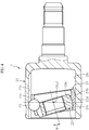
FIG. 3A is a longitudinal sectional view (sectional view taken along the line X-X ofFIG. 3B ) for illustrating a plunging type constant velocity universal joint incorporated into the above-mentioned rear-wheel drive shaft. -
FIG. 3B is a transverse sectional view (sectional view taken along the plane including a joint center ofFIG. 3A ) for illustrating the above-mentioned plunging type constant velocity universal joint. -
FIG. 4 is a longitudinal sectional view for illustrating a state in which the plunging type constant velocity universal joint ofFIGS. 3 forms a maximum operating angle. -
FIG. 5A is a longitudinal sectional view (sectional view taken along the line Y-Y ofFIG. 5B ) for illustrating a fixed type constant velocity universal joint incorporated into the above-mentioned rear-wheel drive shaft. -
FIG. 5B is a transverse sectional view (sectional view taken along the plane including a joint center ofFIG. 5A ) for illustrating the above-mentioned fixed type constant velocity universal joint. -
FIG. 6 is a longitudinal sectional view for illustrating the plunging type constant velocity universal joint, in which an upper half is an illustration of a product of the present invention, and a lower half is an illustration of a comparative product. -
FIG. 7 is a transverse sectional view for illustrating the plunging type constant velocity universal joint taken along the plane including a joint center, in which an upper half is an illustration of the product of the present invention, and a lower half is an illustration of the comparative product. -
FIG. 8 is a longitudinal sectional view for illustrating an inner joint member of the plunging type constant velocity universal joint, in which an upper half is an illustration of the product of the present invention, and a lower half is an illustration of the comparative product. -
FIG. 9A is a plan view for illustrating a state in which a front-wheel drive shaft is mounted so as to be inclined with respect to a vehicle width direction. -
FIG. 9B is a plan view for illustrating a state in which a rear-wheel drive shaft is mounted so as to be parallel to the vehicle width direction. - Now, an embodiment of the present invention is described with reference to the drawings.
-
FIG. 1 is an illustration of a power transmission mechanism for a rear-wheel drive vehicle (such as an FR vehicle) of an independent suspension type. In this power transmission mechanism, a rotational drive force output from an engine E is transmitted to a differential gear G through a transmission M and a propeller shaft PS, and then is transmitted to right and left rear wheels (wheel W) through right and left rear-wheel drive shafts 1. - As illustrated in
FIG. 2 , the rear-wheel drive shaft 1 comprises a plunging type constant velocityuniversal joint 2, a fixed type constant velocityuniversal joint 3, and anintermediate shaft 4. The plunging type constant velocityuniversal joint 2 is provided on an inboard side (right side inFIG. 2 ) and is configured to allow both axial displacement and angular displacement. The fixed type constant velocityuniversal joint 3 is provided on an outboard side (left side inFIG. 2 ) and is configured to allow only angular displacement. The rear-wheel drive shaft 1 has the structure in which both the constant velocityuniversal joints intermediate shaft 4. The plunging type constant velocityuniversal joint 2 on the inboard side is coupled to the differential gear G, and the fixed type constant velocityuniversal joint 3 on the outboard side is coupled to the wheel W (seeFIG. 1 ). - As illustrated in
FIGS. 3 , the plunging type constant velocityuniversal joint 2 comprises an outerjoint member 21, an innerjoint member 22, eightballs 23, and acage 24. The outerjoint member 21 is mounted to the differential gear G (seeFIG. 1 ). The innerjoint member 22 is mounted to an inboard-side end portion of the intermediate shaft 4 (seeFIG. 2 ). The eightballs 23 are configured to transmit torque between the outerjoint member 21 and the innerjoint member 22. Thecage 24 is configured to retain the eightballs 23. - The outer
joint member 21 integrally comprises amouth section 21a and astem section 21b. Themouth section 21a has a cup shape that is open toward one side in an axial direction of the joint (outboard side or left side inFIG. 3A ). Thestem section 21b extends from a bottom portion of themouth section 21a to another side in the axial direction (inboard side or right side inFIG. 3A ). Eightlinear track grooves 21d extending in the axial direction are formed in a cylindrical innerperipheral surface 21c of themouth section 21a. Aspline 21e to be inserted into a spline hole of the differential gear G is formed in an outer peripheral surface of an inboard-side end portion of thestem section 21b. Themouth section 21a and thestem section 21b may be integrally made of the same material, or may be joined to each other by, for example, welding after themouth section 21a and thestem section 21b are formed into separate sections. - A
spline hole 22c into which theintermediate shaft 4 is to be inserted is formed along an axial center of the innerjoint member 22. Eightlinear track grooves 22e extending in the axial direction are formed in a spherical outerperipheral surface 22d of the innerjoint member 22. That is, the innerjoint member 22 integrally comprises acylindrical portion 22a and a plurality of protrudingportions 22b. Thecylindrical portion 22a has thespline hole 22c. The plurality of protrudingportions 22b protrude from thecylindrical portion 22a radially outward. Thetrack grooves 22e are formed in circumferential regions between the plurality of protrudingportions 22b. Radially outer surfaces of the plurality of protrudingportions 22b form the spherical outerperipheral surface 22d of the innerjoint member 22. - The
track grooves 21d of the outerjoint member 21 and thetrack grooves 22e of the innerjoint member 22 are opposed to each other in a radial direction to form eight ball tracks, and theballs 23 are arranged one by one in the ball tracks, respectively. A transverse sectional shape of each of thetrack grooves track grooves balls 23 are held in contact with each other at a contact angle of from about 30° to about 45°, in other words, held in so-called angular contact with each other. A transverse sectional shape of each of thetrack grooves track grooves balls 23 may be held in so-called circular contact with each other. - The
cage 24 has eightpockets 24a configured to retain theballs 23. All the eightpockets 24a have the same shape, and are arranged at equal intervals in a circumferential direction of thecage 24. An outer peripheral surface of thecage 24 comprises aspherical portion 24b andconical portions 24c. Thespherical portion 24b is held in slide contact with the cylindrical innerperipheral surface 21c of the outerjoint member 21. Theconical portions 24c extend in tangential directions from both end portions of thespherical portion 24b in the axial direction. As illustrated inFIG. 4 , when the plunging type constant velocityuniversal joint 2 forms a maximum operating angle θ, each of theconical portions 24c functions as a stopper configured to restrain further increase in operating angle through linear contact with the innerperipheral surface 21c of the outerjoint member 21. An inclination angle of theconical portions 24c with respect to the axial center of thecage 24 is set to a half of a value of the maximum operating angle θ of the plunging type constant velocityuniversal joint 2. Aspherical portion 24d is formed on the inner peripheral surface of thecage 24, and is held in slide contact with the spherical outerperipheral surface 22d of the innerjoint member 22. Through axial sliding of thespherical portion 24b of the outer peripheral surface of thecage 24 and the cylindrical innerperipheral surface 21c of the outerjoint member 21, axial displacement is allowed between the outerjoint member 21 and the innerjoint member 22. - As illustrated in
FIG. 3 , a curvature center O24b of thespherical portion 24b of the outer peripheral surface of thecage 24, and a curvature center O24d of thespherical portion 24d of the inner peripheral surface of the cage 24 (that is, curvature center of the spherical outerperipheral surface 22d of the inner joint member 22) are offset to opposite sides in the axial direction with respect to joint center O (s) by an equal distance. In the illustrated example, the curvature center O24b of thespherical portion 24b of the outer peripheral surface of thecage 24 is offset to the inboard side (joint deep side) with respect to the joint center 0(s), and the curvature center O24d of thespherical portion 24d of the inner peripheral surface of thecage 24 is offset to the outboard side (joint opening side) with respect to the joint center O(s). With this configuration, at a freely-selected operating angle, theballs 23 retained by thecage 24 are always arranged within a plane obtained by bisection of the operating angle, thereby ensuring a constant velocity characteristic between the outerjoint member 21 and the innerjoint member 22. - As illustrated in
FIGS. 5 , the fixed type type constant velocityuniversal joint 3 comprises an outerjoint member 31, an innerjoint member 32, eightballs 33, and acage 34. The outerjoint member 31 is mounted to the wheel W (seeFIG. 1 ). The innerjoint member 32 is mounted to an outboard-side end portion of the intermediate shaft 4 (seeFIG. 2 ). The eightballs 33 are configured to transmit torque between the outerjoint member 31 and the innerjoint member 32. Thecage 34 is configured to retain the eightballs 33. - The outer
joint member 31 integrally comprises amouth section 31a and astem section 31b. Themouth section 31a has a cup shape that is open toward one side in an axial direction of the joint (inboard side or right side inFIG. 5A ). Thestem section 31b extends from a bottom portion of themouth section 31a to another side in the axial direction (outboard side or left side inFIG. 5A ). Eight arc-shapedtrack grooves 31d extending in the axial direction are formed in a spherical innerperipheral surface 31c of themouth section 31a. Aspline 31e to be inserted into a spline hole on the wheel W side is formed in an outer peripheral surface of thestem section 31b. Themouth section 31a and thestem section 31b may be integrally made of the same material, or may be joined to each other by, for example, welding after themouth section 31a and thestem section 31b are formed into separate sections . Further, a through hole extending in the axial direction may be formed along the axial centers of themouth section 31a and thestem section 31b. - A
spline hole 32c into which the intermediate shaft 4 (seeFIG. 2 ) is to be inserted is formed along an axial center of the innerjoint member 32. Eight arc-shapedtrack grooves 32e extending in the axial direction are formed in a spherical outerperipheral surface 32d of the innerjoint member 32. That is, the innerjoint member 32 integrally comprises acylindrical portion 32a and a plurality of protrudingportions 32b. Thecylindrical portion 32a has thespline hole 32c. The plurality of protrudingportions 32b protrude from thecylindrical portion 32a radially outward. Thetrack grooves 32e are formed in circumferential regions between the plurality of protrudingportions 32b. Radially outer surfaces of the plurality of protrudingportions 32b form the spherical outerperipheral surface 32d of the innerjoint member 32. - The
track grooves 31d of the outerjoint member 31 and thetrack grooves 32e of the innerjoint member 32 are opposed to each other in a radial direction to form eight ball tracks, and theballs 33 are arranged one by one in the ball tracks, respectively. A transverse sectional shape of each of thetrack grooves track grooves balls 33 are held in contact with each other at a contact angle of from about 30° to about 45°, in other words, held in so-called angular contact with each other. A transverse sectional shape of each of thetrack grooves track grooves balls 33 may be held in so-called circular contact with each other. - A curvature center O31d of the
track grooves 31d of the outerjoint member 31, and a curvature center O32e of thetrack grooves 32e of the innerjoint member 32 are offset to opposite sides in the axial direction with respect to a joint center O(f) by an equal distance. In the illustrated example, the curvature center O31d of thetrack grooves 31d of the outerjoint member 31 is offset to the inboard side (joint opening side) with respect to the joint center O(f), and the curvature center O32e of thetrack grooves 32e of the innerjoint member 32 is offset to the outboard side (joint deep side) with respect to the joint center O(f). With this configuration, at a freely-selected operating angle, theballs 33 retained by thecage 34 are always arranged within a plane obtained by bisection of the operating angle, thereby ensuring a constant velocity characteristic between the outerjoint member 31 and the innerjoint member 32. - The
cage 34 has eightpockets 34a configured to retain theballs 33. All the eightpockets 34a have the same shape, and are arranged at equal intervals in a circumferential direction of thecage 34. A spherical outerperipheral surface 34b of thecage 34 is held in slide contact with the spherical innerperipheral surface 31c of the outerjoint member 31. A spherical innerperipheral surface 34c of thecage 34 is held in slide contact with the spherical outerperipheral surface 32d of the innerjoint member 32. A curvature center of the outerperipheral surface 34b of the cage 34 (that is, curvature center of the spherical innerperipheral surface 31c of the outer joint member 31), and a curvature center of the innerperipheral surface 34c (that is, curvature center of the spherical outerperipheral surface 32d of the inner joint member 32) match with the joint center O(f). - As illustrated in
FIG. 2 , as theintermediate shaft 4, a hollow shaft having a throughhole 41 extending in the axial direction can be used. Theintermediate shaft 4 comprises a large-diameter portion 42, small-diameter portions 43, and taperedportions 44. The large-diameter portion 42 is formed at a center of theintermediate shaft 4 in the axial direction. The small-diameter portions 43 are formed at both ends of theintermediate shaft 4 in the axial direction, respectively. Each of the taperedportions 44 connects the large-diameter portion 42 and the small-diameter portion 43. Anannular groove 45 for mounting a boot and aspline 46 are formed in the small-diameter portion 43 of theintermediate shaft 4. The small-diameter portion 43 has a constant outer diameter except for theannular groove 45 and thespline 46. Theintermediate shaft 4 is not limited to the hollow shaft, and a solid shaft may also be used. - The
spline 46 at an inboard-side end portion of theintermediate shaft 4 is press-fitted into thespline hole 22c of the innerjoint member 22 of the plunging type constant velocityuniversal joint 2. Thus, theintermediate shaft 4 and the innerjoint member 22 are coupled to each other in a torque transmittable manner through spline fitting. An annular recessed groove is formed in the inboard-side end portion of theintermediate shaft 4, and asnap ring 47 is fitted into the recessed groove . Through engagement of thesnap ring 47 from the inboard side (shaft end side) of the innerjoint member 22, theintermediate shaft 4 and the innerjoint member 22 are prevented from coming off. - The
spline 46 at an outboard-side end portion of theintermediate shaft 4 is press-fitted into thespline hole 32c of the innerjoint member 32 of the fixed type constant velocityuniversal joint 3. Thus, theintermediate shaft 4 and the innerjoint member 32 are coupled to each other in a torque transmittable manner through spline fitting. An annular recessed groove is formed in the outboard-side end portion of theintermediate shaft 4, and asnap ring 47 is fitted into the recessed groove. Through engagement of thesnap ring 47 from the outboard side (shaft end side) of the innerjoint member 32, theintermediate shaft 4 and the innerjoint member 32 are prevented from coming off. - The plunging type constant velocity
universal joint 2 and the fixed type constant velocityuniversal joint 3 described above are used exclusively for the rear-wheel drive shaft, and hence the maximum operating angle can be set smaller than that of a conventional product that is also usable for a front-wheel drive shaft. In this embodiment, both of the maximum operating angle of the plunging type constant velocityuniversal joint 2 and the maximum operating angle of the fixed type constant velocityuniversal joint 3 are set to 20° or less. In this manner, reduction in weight and size of the plunging type constant velocityuniversal joint 2 and the fixed type constant velocityuniversal joint 3 can be achieved while maintaining load capacity. In the following, internal specifications of the plunging type constant velocityuniversal joint 2 are described in detail. - In Table 1 below and
FIG. 6 to FIG. 8 , the internal specifications of the plunging type constant velocityuniversal joint 2 being the product of the present invention are shown and illustrated in comparison to a comparative product (double offset constant velocity universal joint having a maximum operating angle of 25° and eight balls) having the same ball diameter as that of the product of the present invention. An upper half of each ofFIG. 6 to FIG. 8 is a sectional view of the plunging type constant velocityuniversal joint 2 being the product of the present invention, and a lower half thereof is a sectional view of a plunging type constant velocity universal joint 2' being the comparative product. Each component of the comparative product is denoted by the reference symbol obtained by adding a prime (') to the reference symbol of each component of the product of the present invention.[Table 1] Product of the present invention Comparative product (1) Ball PCD (PCDBALL)/ball diameter 3.3 to 3.6 3.6 to 3.9 (2) Inner ring width (WI) /ball diameter 1.2 to 1.55 1.6 to 1.8 (3) Inner ring thickness (TI)/ball diameter 0.30 to 0.45 0.45 to 0.60 (4) Spline PCD (PCDSPL) /ball diameter 1.70 to 1.85 1.65 to 1.75 (5) Outer-ring outer diameter (D0)/spline PCD (PCDSPL) 2.7 to 3.0 3.0 to 3.3 (6) Cage width (WC)/ball diameter 1.8 to 2.0 2.0 to 2.2 - Parameters described above are defined as follows.
- (1) Ball PCD (pitch circle diameter of the balls) PCDBALL: The ball PCD has a value twice as large as a distance between the axial center of the outer
joint member 21 and a center of theball 23 or between the axial center of the innerjoint member 22 and the center of theball 23. That is, the ball PCD corresponds to a diameter of a circle passing centers of all of theballs 23 under a state in which the operating angle is 0°. - (2) Inner ring width (axial width of the inner joint member) WI: The inner ring width is a maximum axial dimension of the inner
joint member 22. In the illustrated example, the inner ring width is an axial distance between both end surfaces of the innerjoint member 22. - (3) Inner ring thickness (radial thickness of the inner joint member) TI: The inner ring thickness is a radial distance between a groove bottom of the
track groove 22e in a joint center plane P {plane that passes the joint center O(s) and is orthogonal to an axis} and a pitch circle of thespline hole 22c. In the illustrated example, the inner joint member has a constant radial thickness in the axial direction. - (4) Spline PCD (pitch circle diameter of the spline hole of the inner joint member) PCDSPL: The spline PCD is a diameter of a pitch circle of meshing between the
spline hole 22c of the innerjoint member 22 and the spline 46 (seeFIG. 2 ) of theintermediate shaft 4. - (5) Outer-ring outer diameter DO: The outer-ring outer diameter is a maximum outer diameter of the outer
joint member 21. - (6) Cage width WC: The cage width is a maximum axial dimension of the
cage 24. In the illustrated example, the cage width is an axial distance between both end surfaces of thecage 24. - In the following, detailed description is made of a design concept leading to the above-mentioned internal specifications.
- In the plunging type constant velocity
universal joint 2, as the operating angle is increased, a maximum load applied to each of theballs 23 is increased. Accordingly, when the maximum operating angle is reduced as described above, the maximum load applied to each of theballs 23 is reduced. Thus, the innerjoint member 22 to be held in contact with theballs 23 has a sufficient margin of strength. As a result, the radial thickness of the innerjoint member 22 can be reduced. Therefore, without causing reduction in load capacity and durability, the pitch circle diameter of thetrack grooves 22e of the innerjoint member 22, that is, the pitch circle diameter of theballs 23 arranged in thetrack grooves 22e can be reduced as compared to that of the comparative product {PCDBALL<PCDBALL', see the row (1) in Table 1 above} . In this manner, a size of the plunging type constant velocityuniversal joint 2 in the radial direction is reduced, and thus reduction in weight can be achieved. - The comparative product has a large maximum operating angle, and hence a circumferential length of each of
pockets 24a' of acage 24' is increased. Thus, it has been required to increase a diameter of thecage 24' in order to ensure the circumferential length of each of thepockets 24a'. Therefore, a diameter of an outer peripheral surface of an innerjoint member 22' to be held in slide contact with an inner peripheral surface of thecage 24' is increased. Consequently, the innerjoint member 22' has an excessively large thickness that is more than necessary in view of strength. In contrast, in the product of the present invention, when the maximum operating angle is reduced as described above, a movement amount of each of theballs 23 in the circumferential direction with respect to thecage 24 is reduced, thereby being capable of reducing the circumferential dimension of each of thepockets 24a of the cage 24 (Lp<Lp'). Accordingly, while maintaining the circumferential dimension of apillar portion 24e between thepockets 24a (Lc≈Lc'), the diameter of thecage 24 can be reduced, and the diameter of the outerperipheral surface 22d of the innerjoint member 22 to be held in slide contact with thespherical portion 24d of the inner peripheral surface of thecage 24 can be reduced. As a result, a thickness of the innerjoint member 22 can be reduced so as to be set to a minimum thickness necessary in view of strength {TI<TI', see the row (3) in Table 1 above } . Further, the pitch circle diameter of theballs 23 is reduced as described above, thereby being capable of reducing a size of the plunging type constant velocityuniversal joint 2 in the radial direction. - Through reduction of the maximum operating angle of the plunging type constant velocity
universal joint 2, the maximum load applied to each of theballs 23 is reduced as described above, with the result that thecage 24 held in contact with theballs 23 has a sufficient margin of strength. Accordingly, an axial thickness of an annular portion formed at each end of thecage 24 in the axial direction can be reduced while maintaining durability equivalent to that of the comparative product. Thus, an axial width of theentire cage 24 can be reduced, and hence reduction in weight can be achieved {WC<WC', see the row (6) in Table 1 above}. - Through reduction of the maximum operating angle of the plunging type constant velocity
universal joint 2, an angle of theconical portions 24c of the outer peripheral surface of thecage 24 with respect to the axial center can be reduced, and can be set to 10° or less in this embodiment. With this configuration, a thickness (for example, a thickness TC at a joint-opening-side end portion) of a thin portion of thecage 24 can be increased, and hence strength of thecage 24 can be increased. - When the maximum operating angle of the plunging type constant velocity
universal joint 2 is reduced, the radial thickness TI of the innerjoint member 22 can be reduced as described above, with the result that a diameter of thespline hole 22c of the innerjoint member 22 can be increased {PCDSPL>PCDSPL', see the row (4) in Table 1 above}. In this manner, theintermediate shaft 4 to be inserted into thespline hole 22c is increased in diameter, and thus torsional strength can be enhanced. Further, when the maximum operating angle of the plunging type constant velocityuniversal joint 2 is reduced, the pitch circle diameter of theballs 23 can be reduced as described above, with the result that a diameter of the outerjoint member 21 can be reduced. From the above description, in the product of the present invention, a ratio DO/PCDSPL of the outer diameter DO of the outerjoint member 21 to the pitch circle diameter PCDSPL of thespline hole 22c of the innerjoint member 22 can be set smaller than that of the comparative product {DO/PCDSPL<DO'/PCDSPL', see the row (5) in Table 1 above}. In this manner, reduction in weight and size of the plunging type constant velocityuniversal joint 2, and improvement in strength of theintermediate shaft 4 can be achieved at the same time. - When the maximum operating angle of the plunging type constant velocity
universal joint 2 is reduced, a movement amount of each of theballs 23 in the axial direction with respect to the innerjoint member 22 is reduced. Specifically, as illustrated inFIG. 8 , an axial length (track effective length) of a locus of a contact point between thetrack groove 22e of the innerjoint member 22 and theball 23 is smaller in the product of the present invention having a small maximum operating angle than in the comparative product having a large maximum operating angle (ZI<ZI'). With this configuration, in the product of the present invention, the axial length of each of thetrack grooves 22e of the innerjoint member 22 and the axial width of the entire innerjoint member 22 can be reduced as compared to those of the comparative product {WI<WI', see the row (2) in Table 1 above}. - However, when the axial width of the inner
joint member 22 is excessively small, thespline hole 22c formed along the axial center of the innerjoint member 22 has an insufficient axial length, which may lead to insufficient strength of a spline fitting portion between the innerjoint member 22 and the intermediate shaft 4 (seeFIG. 2 ). In the plunging type constant velocityuniversal joint 2 being the product of the present invention, through reduction of the maximum operating angle, the radial thickness of the innerj oint member 22 can be reduced as described above, and hence a diameter of thespline hole 22c of the innerjoint member 22 can be increased. Accordingly, while maintaining the contact pressure for each spline tooth (that is, while maintaining strength of the spline fitting portion), the axial length of thespline hole 22c of the innerjoint member 22 can be reduced. In the above-mentioned manner, through reduction of the axial length of each of thetrack grooves 22e of the innerjoint member 22 and the axial length of thespline hole 22c, the axial width of the entire innerjoint member 22 can be reduced as described above, and hence reduction in weight can be achieved. - As described above, according to the present invention, in consideration of various conditions obtained by reducing the maximum operating angle of the plunging type constant velocity universal joint, study is made on the internal specifications of the plunging type constant velocity universal joint, thereby reducing the weight and size of the plunging type constant velocity universal joint while maintaining torque load capacity equivalent to that of the comparative product. Thus, there can be launched a new series of plunging type constant velocity universal joints each having a small weight and a small size and being usable exclusively for the rear-wheel drive shaft.
- Incidentally, when the plunging type constant velocity universal joint rotates under a state of forming a high operating angle, there is a risk in that noise is generated. In order to prevent generation of noise during such high operating angle, in the related-art plunging type constant velocity universal joint, a track PCD gap (difference between a pitch circle diameter of the track grooves of the outer joint member and a pitch circle diameter of the track grooves of the inner joint member), a gap between the outer joint member and the cage (difference between a diameter of the cylindrical inner peripheral surface of the outer joint member and a diameter of the spherical portion of the outer peripheral surface of the cage), and a spherical gap between the cage and the inner joint member (difference between the diameter of the spherical portion of the inner peripheral surface of the cage and a diameter of the spherical outer peripheral surface of the inner joint member) are each required to be set to a significantly small value. In contrast, in the above-mentioned plunging type constant velocity
universal joint 2, the maximum operating angle is small, and the risk of noise can be reduced. Accordingly, the above-mentioned gaps can be set to values larger than those of the conventional product, and hence the product of the present invention is advantageous in view of manufacture. - Further, the related-art plunging type constant velocity universal joint is used also for the front-wheel drive shaft. Thus, as countermeasures against idling vibration, the inner peripheral surface of the cage is processed into a special shape so that a relatively large axial gap is formed between the inner peripheral surface of the cage and the outer peripheral surface of the inner joint member (for example, see
FIG. 3 andFIG. 4 in Patent Literature 1 above). In contrast, the above-mentioned plunging type constant velocityuniversal joint 2 is used exclusively for the rear-wheel drive shaft. Thus, the countermeasures against idling vibration are not required, and the inner peripheral surface (portion to be held in slide contact with the inner joint member) of the cage can be formed into a simple spherical shape . Accordingly, the product of the present invention is more advantageous than the conventional product in view of manufacture. - Preferable ranges of the gaps, which are set in consideration of the above-mentioned circumstances, are shown in Table 2 below (unit: mm). Axial gaps between the pocket surfaces of the cage and the balls are equal to those of the conventional product. When minute axial gaps are formed between the pocket surfaces of the cage and the balls, rolling performance of the balls is improved, and torque transmitting efficiency is improved.
[Table 2] Track PCD gap 0.005 to 0.200 Gap between outer ring and cage 0.005 to 0.300 Spherical gap between cage and inner ring 0.005 to 0.100 Axial gap between cage and inner ring 0.005 to 0.300 Gap between cage pocket and ball 0.005 to 0.050 - The present invention is not limited to the above-mentioned embodiment. For example, the above-mentioned plunging type constant velocity universal joint is usable not only for the rear-wheel drive shaft of a rear-wheel drive vehicle (such as an FR vehicle) that drives only rear wheels, but also for a rear-wheel drive shaft of a four-wheel drive vehicle (in particular, a four-wheel drive vehicle in which rear wheels serve as main driving wheels) . In a sport utility vehicle (SUV), wheels move up and down greatly, and angular displacement of drive shafts is large. Accordingly, the plunging type constant velocity universal joint having the low operating angle as described above is not applicable in some cases. Therefore, it is preferred that the above-mentioned plunging type constant velocity universal joint be applied to a rear-wheel drive shaft of a rear-wheel drive automobile or a four-wheel drive automobile.
-
- 1
- rear-wheel drive shaft
- 2
- plunging type constant velocity universal joint
- 21
- outer joint member
- 22
- inner joint member
- 23
- ball
- 24
- cage
- 3
- fixed type constant velocity universal joint
- 31
- outer joint member
- 32
- inner joint member
- 33
- ball
- 34
- cage
- 4
- intermediate shaft
- E
- engine
- G
- differential gear
- M
- transmission
- PS
- propeller shaft
- W
- wheel
Claims (4)
- A plunging type constant velocity universal joint for a rear-wheel drive shaft, comprising:an outer joint member having a cylindrical inner peripheral surface in which eight track grooves extending in an axial direction of the plunging type constant velocity universal joint are formed;an inner joint member having a spherical outer peripheral surface in which eight track grooves extending in the axial direction are formed, and having a spline hole formed along an axial center of the inner joint member;eight balls arranged in ball tracks formed by the track grooves of the outer joint member and the track grooves of the inner joint member; anda cage, which has eight pockets configured to receive the balls, and is held in slide contact with the inner peripheral surface of the outer joint member and the outer peripheral surface of the inner joint member,wherein a curvature center of a spherical portion formed on an outer peripheral surface of the cage and a curvature center of a spherical portion formed on an inner peripheral surface of the cage are offset to opposite sides in the axial direction with respect to a joint center by an equal distance,wherein a ratio PCDBALL/DBALL of a pitch circle diameter PCDBALL of the balls to a diameter DBALL of each of the balls is set from 3.3 to 3.6, andwherein a ratio TI/DBALL of a radial thickness TI of the inner joint member to the diameter DBALL of each of the balls is set from 0.30 to 0.45.
- The plunging type constant velocity universal joint according to claim 1, wherein a ratio PCDSPL/DBALL of a pitch circle diameter PCDSPL of the spline hole of the inner joint member to the diameter DBALL of each of the balls is set from 1.70 to 1.85.
- The plunging type constant velocity universal joint according to claim 1 or 2, wherein a ratio DO/PCDSPL of an outer diameter DO of the outer joint member to the pitch circle diameter PCDSPL of the spline hole of the inner joint member is set from 2.7 to 3.0.
- The plunging type constant velocity universal joint according to any one of claims 1 to 3, wherein the plunging type constant velocity universal joint has a maximum operating angle of 20° or less.
Applications Claiming Priority (3)
| Application Number | Priority Date | Filing Date | Title |
|---|---|---|---|
| JP2017052646 | 2017-03-17 | ||
| JP2018037352A JP7292008B2 (en) | 2017-03-17 | 2018-03-02 | Sliding constant velocity universal joint for rear wheel drive shaft |
| PCT/JP2018/008949 WO2018168631A1 (en) | 2017-03-17 | 2018-03-08 | Sliding-type constant velocity universal joint for rear-wheel drive shaft |
Publications (3)
| Publication Number | Publication Date |
|---|---|
| EP3597952A1 true EP3597952A1 (en) | 2020-01-22 |
| EP3597952A4 EP3597952A4 (en) | 2020-12-09 |
| EP3597952B1 EP3597952B1 (en) | 2024-10-16 |
Family
ID=63718026
Family Applications (1)
| Application Number | Title | Priority Date | Filing Date |
|---|---|---|---|
| EP18767261.3A Active EP3597952B1 (en) | 2017-03-17 | 2018-03-08 | Sliding-type constant velocity universal joint for rear-wheel drive shaft |
Country Status (3)
| Country | Link |
|---|---|
| US (1) | US11359677B2 (en) |
| EP (1) | EP3597952B1 (en) |
| JP (1) | JP7292008B2 (en) |
Cited By (1)
| Publication number | Priority date | Publication date | Assignee | Title |
|---|---|---|---|---|
| EP4394200A4 (en) * | 2021-08-26 | 2024-12-18 | NTN Corporation | Plunging type constant velocity universal joint |
Families Citing this family (3)
| Publication number | Priority date | Publication date | Assignee | Title |
|---|---|---|---|---|
| JP7412099B2 (en) * | 2019-07-05 | 2024-01-12 | Ntn株式会社 | Power transmission mechanism and vehicle |
| JP7837162B2 (en) * | 2021-11-30 | 2026-03-30 | Ntn株式会社 | Sliding constant velocity universal joint |
| JP7599456B2 (en) * | 2022-06-16 | 2024-12-13 | Ntn株式会社 | Sliding constant velocity joint |
Family Cites Families (11)
| Publication number | Priority date | Publication date | Assignee | Title |
|---|---|---|---|---|
| CA930562A (en) | 1969-12-11 | 1973-07-24 | G. Fisher Leslie | Universal joints |
| JPS5226657Y1 (en) * | 1975-02-19 | 1977-06-17 | ||
| JPS5226657A (en) | 1975-08-26 | 1977-02-28 | Tsukishima Kikai Co Ltd | Horizontally rotating disc type filtering device |
| JP3859295B2 (en) * | 1996-06-28 | 2006-12-20 | Ntn株式会社 | Sliding type constant velocity universal joint |
| JP2007032648A (en) * | 2005-07-25 | 2007-02-08 | Ntn Corp | Large operation angle fixing type constant velocity universal joint |
| JP2009250342A (en) | 2008-04-04 | 2009-10-29 | Ntn Corp | Constant velocity universal joint |
| US8070611B2 (en) | 2009-05-13 | 2011-12-06 | Gkn Driveline North America, Inc. | Plunging cross-track constant velocity joint |
| JP5872150B2 (en) | 2010-11-01 | 2016-03-01 | Ntn株式会社 | Rear wheel drive shaft |
| JP5928942B2 (en) | 2012-03-12 | 2016-06-01 | 株式会社ショーワ | Constant velocity joint |
| US9926985B2 (en) | 2013-08-09 | 2018-03-27 | Hyundai Wia Corporation | Sliding ball type constant velocity joint for vehicles |
| CN112020613B (en) * | 2018-04-24 | 2023-11-14 | Ntn株式会社 | Sliding constant velocity universal coupling for transmission shaft |
-
2018
- 2018-03-02 JP JP2018037352A patent/JP7292008B2/en active Active
- 2018-03-08 EP EP18767261.3A patent/EP3597952B1/en active Active
- 2018-03-08 US US16/494,393 patent/US11359677B2/en active Active
Cited By (1)
| Publication number | Priority date | Publication date | Assignee | Title |
|---|---|---|---|---|
| EP4394200A4 (en) * | 2021-08-26 | 2024-12-18 | NTN Corporation | Plunging type constant velocity universal joint |
Also Published As
| Publication number | Publication date |
|---|---|
| EP3597952A4 (en) | 2020-12-09 |
| EP3597952B1 (en) | 2024-10-16 |
| US20200240476A1 (en) | 2020-07-30 |
| JP2018155404A (en) | 2018-10-04 |
| US11359677B2 (en) | 2022-06-14 |
| JP7292008B2 (en) | 2023-06-16 |
Similar Documents
| Publication | Publication Date | Title |
|---|---|---|
| EP3597952B1 (en) | Sliding-type constant velocity universal joint for rear-wheel drive shaft | |
| KR20120023789A (en) | Plunging cross-track constant velocity joint | |
| US12203510B2 (en) | Plunging type constant velocity universal joint for propeller shaft | |
| EP3597951B1 (en) | Fixed ball constant-velocity universal joint used in rear-wheel drive shaft | |
| JP7437868B2 (en) | Sliding type constant velocity universal joint for propeller shaft | |
| CN110431324B (en) | Sliding type constant velocity universal joint for rear wheel drive shaft | |
| US12359695B2 (en) | Fixed-type constant velocity universal joint | |
| US11359676B2 (en) | Fixed-type constant velocity universal joint | |
| EP3597949B1 (en) | Rear-wheel drive shaft | |
| US11326649B2 (en) | Rear-wheel drive shaft | |
| JP7224107B2 (en) | Sliding constant velocity universal joint for rear wheel drive shaft | |
| JP6899675B2 (en) | Fixed constant velocity universal joint used for drive shafts for rear wheels | |
| JP6736509B2 (en) | Fixed type constant velocity universal joint used for rear wheel drive shaft | |
| WO2018168634A1 (en) | Sliding-type constant velocity universal joint for rear-wheel drive shaft |
Legal Events
| Date | Code | Title | Description |
|---|---|---|---|
| STAA | Information on the status of an ep patent application or granted ep patent |
Free format text: STATUS: THE INTERNATIONAL PUBLICATION HAS BEEN MADE |
|
| PUAI | Public reference made under article 153(3) epc to a published international application that has entered the european phase |
Free format text: ORIGINAL CODE: 0009012 |
|
| STAA | Information on the status of an ep patent application or granted ep patent |
Free format text: STATUS: REQUEST FOR EXAMINATION WAS MADE |
|
| 17P | Request for examination filed |
Effective date: 20191002 |
|
| AK | Designated contracting states |
Kind code of ref document: A1 Designated state(s): AL AT BE BG CH CY CZ DE DK EE ES FI FR GB GR HR HU IE IS IT LI LT LU LV MC MK MT NL NO PL PT RO RS SE SI SK SM TR |
|
| AX | Request for extension of the european patent |
Extension state: BA ME |
|
| DAV | Request for validation of the european patent (deleted) | ||
| DAX | Request for extension of the european patent (deleted) | ||
| A4 | Supplementary search report drawn up and despatched |
Effective date: 20201111 |
|
| RIC1 | Information provided on ipc code assigned before grant |
Ipc: F16D 3/227 20060101AFI20201105BHEP |
|
| STAA | Information on the status of an ep patent application or granted ep patent |
Free format text: STATUS: EXAMINATION IS IN PROGRESS |
|
| 17Q | First examination report despatched |
Effective date: 20221123 |
|
| GRAP | Despatch of communication of intention to grant a patent |
Free format text: ORIGINAL CODE: EPIDOSNIGR1 |
|
| STAA | Information on the status of an ep patent application or granted ep patent |
Free format text: STATUS: GRANT OF PATENT IS INTENDED |
|
| INTG | Intention to grant announced |
Effective date: 20240611 |
|
| GRAS | Grant fee paid |
Free format text: ORIGINAL CODE: EPIDOSNIGR3 |
|
| GRAA | (expected) grant |
Free format text: ORIGINAL CODE: 0009210 |
|
| STAA | Information on the status of an ep patent application or granted ep patent |
Free format text: STATUS: THE PATENT HAS BEEN GRANTED |
|
| AK | Designated contracting states |
Kind code of ref document: B1 Designated state(s): AL AT BE BG CH CY CZ DE DK EE ES FI FR GB GR HR HU IE IS IT LI LT LU LV MC MK MT NL NO PL PT RO RS SE SI SK SM TR |
|
| REG | Reference to a national code |
Ref country code: GB Ref legal event code: FG4D |
|
| REG | Reference to a national code |
Ref country code: CH Ref legal event code: EP Ref country code: DE Ref legal event code: R096 Ref document number: 602018075513 Country of ref document: DE |
|
| REG | Reference to a national code |
Ref country code: IE Ref legal event code: FG4D |
|
| REG | Reference to a national code |
Ref country code: LT Ref legal event code: MG9D |
|
| REG | Reference to a national code |
Ref country code: NL Ref legal event code: MP Effective date: 20241016 |
|
| REG | Reference to a national code |
Ref country code: AT Ref legal event code: MK05 Ref document number: 1733131 Country of ref document: AT Kind code of ref document: T Effective date: 20241016 |
|
| PG25 | Lapsed in a contracting state [announced via postgrant information from national office to epo] |
Ref country code: NL Free format text: LAPSE BECAUSE OF FAILURE TO SUBMIT A TRANSLATION OF THE DESCRIPTION OR TO PAY THE FEE WITHIN THE PRESCRIBED TIME-LIMIT Effective date: 20241016 |
|
| PG25 | Lapsed in a contracting state [announced via postgrant information from national office to epo] |
Ref country code: NL Free format text: LAPSE BECAUSE OF FAILURE TO SUBMIT A TRANSLATION OF THE DESCRIPTION OR TO PAY THE FEE WITHIN THE PRESCRIBED TIME-LIMIT Effective date: 20241016 |
|
| PG25 | Lapsed in a contracting state [announced via postgrant information from national office to epo] |
Ref country code: PT Free format text: LAPSE BECAUSE OF FAILURE TO SUBMIT A TRANSLATION OF THE DESCRIPTION OR TO PAY THE FEE WITHIN THE PRESCRIBED TIME-LIMIT Effective date: 20250217 Ref country code: HR Free format text: LAPSE BECAUSE OF FAILURE TO SUBMIT A TRANSLATION OF THE DESCRIPTION OR TO PAY THE FEE WITHIN THE PRESCRIBED TIME-LIMIT Effective date: 20241016 Ref country code: IS Free format text: LAPSE BECAUSE OF FAILURE TO SUBMIT A TRANSLATION OF THE DESCRIPTION OR TO PAY THE FEE WITHIN THE PRESCRIBED TIME-LIMIT Effective date: 20250216 |
|
| PG25 | Lapsed in a contracting state [announced via postgrant information from national office to epo] |
Ref country code: FI Free format text: LAPSE BECAUSE OF FAILURE TO SUBMIT A TRANSLATION OF THE DESCRIPTION OR TO PAY THE FEE WITHIN THE PRESCRIBED TIME-LIMIT Effective date: 20241016 |
|
| PG25 | Lapsed in a contracting state [announced via postgrant information from national office to epo] |
Ref country code: BG Free format text: LAPSE BECAUSE OF FAILURE TO SUBMIT A TRANSLATION OF THE DESCRIPTION OR TO PAY THE FEE WITHIN THE PRESCRIBED TIME-LIMIT Effective date: 20241016 |
|
| PG25 | Lapsed in a contracting state [announced via postgrant information from national office to epo] |
Ref country code: ES Free format text: LAPSE BECAUSE OF FAILURE TO SUBMIT A TRANSLATION OF THE DESCRIPTION OR TO PAY THE FEE WITHIN THE PRESCRIBED TIME-LIMIT Effective date: 20241016 |
|
| PG25 | Lapsed in a contracting state [announced via postgrant information from national office to epo] |
Ref country code: NO Free format text: LAPSE BECAUSE OF FAILURE TO SUBMIT A TRANSLATION OF THE DESCRIPTION OR TO PAY THE FEE WITHIN THE PRESCRIBED TIME-LIMIT Effective date: 20250116 |
|
| PG25 | Lapsed in a contracting state [announced via postgrant information from national office to epo] |
Ref country code: AT Free format text: LAPSE BECAUSE OF FAILURE TO SUBMIT A TRANSLATION OF THE DESCRIPTION OR TO PAY THE FEE WITHIN THE PRESCRIBED TIME-LIMIT Effective date: 20241016 Ref country code: LV Free format text: LAPSE BECAUSE OF FAILURE TO SUBMIT A TRANSLATION OF THE DESCRIPTION OR TO PAY THE FEE WITHIN THE PRESCRIBED TIME-LIMIT Effective date: 20241016 Ref country code: GR Free format text: LAPSE BECAUSE OF FAILURE TO SUBMIT A TRANSLATION OF THE DESCRIPTION OR TO PAY THE FEE WITHIN THE PRESCRIBED TIME-LIMIT Effective date: 20250117 |
|
| PG25 | Lapsed in a contracting state [announced via postgrant information from national office to epo] |
Ref country code: PL Free format text: LAPSE BECAUSE OF FAILURE TO SUBMIT A TRANSLATION OF THE DESCRIPTION OR TO PAY THE FEE WITHIN THE PRESCRIBED TIME-LIMIT Effective date: 20241016 |
|
| PG25 | Lapsed in a contracting state [announced via postgrant information from national office to epo] |
Ref country code: RS Free format text: LAPSE BECAUSE OF FAILURE TO SUBMIT A TRANSLATION OF THE DESCRIPTION OR TO PAY THE FEE WITHIN THE PRESCRIBED TIME-LIMIT Effective date: 20250116 |
|
| PG25 | Lapsed in a contracting state [announced via postgrant information from national office to epo] |
Ref country code: SM Free format text: LAPSE BECAUSE OF FAILURE TO SUBMIT A TRANSLATION OF THE DESCRIPTION OR TO PAY THE FEE WITHIN THE PRESCRIBED TIME-LIMIT Effective date: 20241016 |
|
| PG25 | Lapsed in a contracting state [announced via postgrant information from national office to epo] |
Ref country code: DK Free format text: LAPSE BECAUSE OF FAILURE TO SUBMIT A TRANSLATION OF THE DESCRIPTION OR TO PAY THE FEE WITHIN THE PRESCRIBED TIME-LIMIT Effective date: 20241016 |
|
| REG | Reference to a national code |
Ref country code: DE Ref legal event code: R097 Ref document number: 602018075513 Country of ref document: DE |
|
| PG25 | Lapsed in a contracting state [announced via postgrant information from national office to epo] |
Ref country code: EE Free format text: LAPSE BECAUSE OF FAILURE TO SUBMIT A TRANSLATION OF THE DESCRIPTION OR TO PAY THE FEE WITHIN THE PRESCRIBED TIME-LIMIT Effective date: 20241016 |
|
| PG25 | Lapsed in a contracting state [announced via postgrant information from national office to epo] |
Ref country code: RO Free format text: LAPSE BECAUSE OF FAILURE TO SUBMIT A TRANSLATION OF THE DESCRIPTION OR TO PAY THE FEE WITHIN THE PRESCRIBED TIME-LIMIT Effective date: 20241016 |
|
| PG25 | Lapsed in a contracting state [announced via postgrant information from national office to epo] |
Ref country code: SK Free format text: LAPSE BECAUSE OF FAILURE TO SUBMIT A TRANSLATION OF THE DESCRIPTION OR TO PAY THE FEE WITHIN THE PRESCRIBED TIME-LIMIT Effective date: 20241016 |
|
| PG25 | Lapsed in a contracting state [announced via postgrant information from national office to epo] |
Ref country code: CZ Free format text: LAPSE BECAUSE OF FAILURE TO SUBMIT A TRANSLATION OF THE DESCRIPTION OR TO PAY THE FEE WITHIN THE PRESCRIBED TIME-LIMIT Effective date: 20241016 |
|
| PG25 | Lapsed in a contracting state [announced via postgrant information from national office to epo] |
Ref country code: IT Free format text: LAPSE BECAUSE OF FAILURE TO SUBMIT A TRANSLATION OF THE DESCRIPTION OR TO PAY THE FEE WITHIN THE PRESCRIBED TIME-LIMIT Effective date: 20241016 |
|
| PLBE | No opposition filed within time limit |
Free format text: ORIGINAL CODE: 0009261 |
|
| STAA | Information on the status of an ep patent application or granted ep patent |
Free format text: STATUS: NO OPPOSITION FILED WITHIN TIME LIMIT |
|
| PG25 | Lapsed in a contracting state [announced via postgrant information from national office to epo] |
Ref country code: SE Free format text: LAPSE BECAUSE OF FAILURE TO SUBMIT A TRANSLATION OF THE DESCRIPTION OR TO PAY THE FEE WITHIN THE PRESCRIBED TIME-LIMIT Effective date: 20241016 |
|
| 26N | No opposition filed |
Effective date: 20250717 |
|
| PG25 | Lapsed in a contracting state [announced via postgrant information from national office to epo] |
Ref country code: MC Free format text: LAPSE BECAUSE OF FAILURE TO SUBMIT A TRANSLATION OF THE DESCRIPTION OR TO PAY THE FEE WITHIN THE PRESCRIBED TIME-LIMIT Effective date: 20241016 |
|
| REG | Reference to a national code |
Ref country code: CH Ref legal event code: H13 Free format text: ST27 STATUS EVENT CODE: U-0-0-H10-H13 (AS PROVIDED BY THE NATIONAL OFFICE) Effective date: 20251023 |
|
| PG25 | Lapsed in a contracting state [announced via postgrant information from national office to epo] |
Ref country code: LU Free format text: LAPSE BECAUSE OF NON-PAYMENT OF DUE FEES Effective date: 20250308 |
|
| GBPC | Gb: european patent ceased through non-payment of renewal fee |
Effective date: 20250308 |
|
| REG | Reference to a national code |
Ref country code: BE Ref legal event code: MM Effective date: 20250331 |
|
| PG25 | Lapsed in a contracting state [announced via postgrant information from national office to epo] |
Ref country code: GB Free format text: LAPSE BECAUSE OF NON-PAYMENT OF DUE FEES Effective date: 20250308 |
|
| PG25 | Lapsed in a contracting state [announced via postgrant information from national office to epo] |
Ref country code: BE Free format text: LAPSE BECAUSE OF NON-PAYMENT OF DUE FEES Effective date: 20250331 |
|
| PG25 | Lapsed in a contracting state [announced via postgrant information from national office to epo] |
Ref country code: CH Free format text: LAPSE BECAUSE OF NON-PAYMENT OF DUE FEES Effective date: 20250331 |
|
| PG25 | Lapsed in a contracting state [announced via postgrant information from national office to epo] |
Ref country code: IE Free format text: LAPSE BECAUSE OF NON-PAYMENT OF DUE FEES Effective date: 20250308 |
|
| PGFP | Annual fee paid to national office [announced via postgrant information from national office to epo] |
Ref country code: DE Payment date: 20260128 Year of fee payment: 9 |
|
| PGFP | Annual fee paid to national office [announced via postgrant information from national office to epo] |
Ref country code: FR Payment date: 20260209 Year of fee payment: 9 |