EP3597938A1 - Servovalve - Google Patents
Servovalve Download PDFInfo
- Publication number
- EP3597938A1 EP3597938A1 EP18461586.2A EP18461586A EP3597938A1 EP 3597938 A1 EP3597938 A1 EP 3597938A1 EP 18461586 A EP18461586 A EP 18461586A EP 3597938 A1 EP3597938 A1 EP 3597938A1
- Authority
- EP
- European Patent Office
- Prior art keywords
- base
- pipes
- passage
- heat exchanger
- exchanger system
- Prior art date
- Legal status (The legal status is an assumption and is not a legal conclusion. Google has not performed a legal analysis and makes no representation as to the accuracy of the status listed.)
- Granted
Links
Images




Classifications
-
- F—MECHANICAL ENGINEERING; LIGHTING; HEATING; WEAPONS; BLASTING
- F15—FLUID-PRESSURE ACTUATORS; HYDRAULICS OR PNEUMATICS IN GENERAL
- F15B—SYSTEMS ACTING BY MEANS OF FLUIDS IN GENERAL; FLUID-PRESSURE ACTUATORS, e.g. SERVOMOTORS; DETAILS OF FLUID-PRESSURE SYSTEMS, NOT OTHERWISE PROVIDED FOR
- F15B13/00—Details of servomotor systems ; Valves for servomotor systems
- F15B13/02—Fluid distribution or supply devices characterised by their adaptation to the control of servomotors
- F15B13/04—Fluid distribution or supply devices characterised by their adaptation to the control of servomotors for use with a single servomotor
- F15B13/042—Fluid distribution or supply devices characterised by their adaptation to the control of servomotors for use with a single servomotor operated by fluid pressure
- F15B13/043—Fluid distribution or supply devices characterised by their adaptation to the control of servomotors for use with a single servomotor operated by fluid pressure with electrically-controlled pilot valves
- F15B13/0438—Fluid distribution or supply devices characterised by their adaptation to the control of servomotors for use with a single servomotor operated by fluid pressure with electrically-controlled pilot valves the pilot valves being of the nozzle-flapper type
-
- F—MECHANICAL ENGINEERING; LIGHTING; HEATING; WEAPONS; BLASTING
- F16—ENGINEERING ELEMENTS AND UNITS; GENERAL MEASURES FOR PRODUCING AND MAINTAINING EFFECTIVE FUNCTIONING OF MACHINES OR INSTALLATIONS; THERMAL INSULATION IN GENERAL
- F16K—VALVES; TAPS; COCKS; ACTUATING-FLOATS; DEVICES FOR VENTING OR AERATING
- F16K49/00—Means in or on valves for heating or cooling
- F16K49/005—Circulation means for a separate heat transfer fluid
-
- F—MECHANICAL ENGINEERING; LIGHTING; HEATING; WEAPONS; BLASTING
- F15—FLUID-PRESSURE ACTUATORS; HYDRAULICS OR PNEUMATICS IN GENERAL
- F15B—SYSTEMS ACTING BY MEANS OF FLUIDS IN GENERAL; FLUID-PRESSURE ACTUATORS, e.g. SERVOMOTORS; DETAILS OF FLUID-PRESSURE SYSTEMS, NOT OTHERWISE PROVIDED FOR
- F15B21/00—Common features of fluid actuator systems; Fluid-pressure actuator systems or details thereof, not covered by any other group of this subclass
- F15B21/04—Special measures taken in connection with the properties of the fluid
-
- F—MECHANICAL ENGINEERING; LIGHTING; HEATING; WEAPONS; BLASTING
- F16—ENGINEERING ELEMENTS AND UNITS; GENERAL MEASURES FOR PRODUCING AND MAINTAINING EFFECTIVE FUNCTIONING OF MACHINES OR INSTALLATIONS; THERMAL INSULATION IN GENERAL
- F16K—VALVES; TAPS; COCKS; ACTUATING-FLOATS; DEVICES FOR VENTING OR AERATING
- F16K31/00—Actuating devices; Operating means; Releasing devices
- F16K31/02—Actuating devices; Operating means; Releasing devices electric; magnetic
- F16K31/06—Actuating devices; Operating means; Releasing devices electric; magnetic using a magnet, e.g. diaphragm valves, cutting off by means of a liquid
-
- F—MECHANICAL ENGINEERING; LIGHTING; HEATING; WEAPONS; BLASTING
- F16—ENGINEERING ELEMENTS AND UNITS; GENERAL MEASURES FOR PRODUCING AND MAINTAINING EFFECTIVE FUNCTIONING OF MACHINES OR INSTALLATIONS; THERMAL INSULATION IN GENERAL
- F16K—VALVES; TAPS; COCKS; ACTUATING-FLOATS; DEVICES FOR VENTING OR AERATING
- F16K31/00—Actuating devices; Operating means; Releasing devices
- F16K31/02—Actuating devices; Operating means; Releasing devices electric; magnetic
- F16K31/06—Actuating devices; Operating means; Releasing devices electric; magnetic using a magnet, e.g. diaphragm valves, cutting off by means of a liquid
- F16K31/0603—Multiple-way valves
- F16K31/0624—Lift valves
- F16K31/0627—Lift valves with movable valve member positioned between seats
-
- F—MECHANICAL ENGINEERING; LIGHTING; HEATING; WEAPONS; BLASTING
- F16—ENGINEERING ELEMENTS AND UNITS; GENERAL MEASURES FOR PRODUCING AND MAINTAINING EFFECTIVE FUNCTIONING OF MACHINES OR INSTALLATIONS; THERMAL INSULATION IN GENERAL
- F16K—VALVES; TAPS; COCKS; ACTUATING-FLOATS; DEVICES FOR VENTING OR AERATING
- F16K31/00—Actuating devices; Operating means; Releasing devices
- F16K31/02—Actuating devices; Operating means; Releasing devices electric; magnetic
- F16K31/06—Actuating devices; Operating means; Releasing devices electric; magnetic using a magnet, e.g. diaphragm valves, cutting off by means of a liquid
- F16K31/0682—Actuating devices; Operating means; Releasing devices electric; magnetic using a magnet, e.g. diaphragm valves, cutting off by means of a liquid with an articulated or pivot armature
-
- F—MECHANICAL ENGINEERING; LIGHTING; HEATING; WEAPONS; BLASTING
- F28—HEAT EXCHANGE IN GENERAL
- F28F—DETAILS OF HEAT-EXCHANGE AND HEAT-TRANSFER APPARATUS, OF GENERAL APPLICATION
- F28F13/00—Arrangements for modifying heat-transfer, e.g. increasing, decreasing
- F28F13/06—Arrangements for modifying heat-transfer, e.g. increasing, decreasing by affecting the pattern of flow of the heat-exchange media
-
- F—MECHANICAL ENGINEERING; LIGHTING; HEATING; WEAPONS; BLASTING
- F15—FLUID-PRESSURE ACTUATORS; HYDRAULICS OR PNEUMATICS IN GENERAL
- F15B—SYSTEMS ACTING BY MEANS OF FLUIDS IN GENERAL; FLUID-PRESSURE ACTUATORS, e.g. SERVOMOTORS; DETAILS OF FLUID-PRESSURE SYSTEMS, NOT OTHERWISE PROVIDED FOR
- F15B21/00—Common features of fluid actuator systems; Fluid-pressure actuator systems or details thereof, not covered by any other group of this subclass
- F15B21/04—Special measures taken in connection with the properties of the fluid
- F15B21/042—Controlling the temperature of the fluid
- F15B21/0423—Cooling
-
- F—MECHANICAL ENGINEERING; LIGHTING; HEATING; WEAPONS; BLASTING
- F15—FLUID-PRESSURE ACTUATORS; HYDRAULICS OR PNEUMATICS IN GENERAL
- F15B—SYSTEMS ACTING BY MEANS OF FLUIDS IN GENERAL; FLUID-PRESSURE ACTUATORS, e.g. SERVOMOTORS; DETAILS OF FLUID-PRESSURE SYSTEMS, NOT OTHERWISE PROVIDED FOR
- F15B2211/00—Circuits for servomotor systems
- F15B2211/60—Circuit components or control therefor
- F15B2211/62—Cooling or heating means
-
- F—MECHANICAL ENGINEERING; LIGHTING; HEATING; WEAPONS; BLASTING
- F28—HEAT EXCHANGE IN GENERAL
- F28F—DETAILS OF HEAT-EXCHANGE AND HEAT-TRANSFER APPARATUS, OF GENERAL APPLICATION
- F28F2250/00—Arrangements for modifying the flow of the heat exchange media, e.g. flow guiding means; Particular flow patterns
- F28F2250/10—Particular pattern of flow of the heat exchange media
- F28F2250/102—Particular pattern of flow of the heat exchange media with change of flow direction
-
- F—MECHANICAL ENGINEERING; LIGHTING; HEATING; WEAPONS; BLASTING
- F28—HEAT EXCHANGE IN GENERAL
- F28F—DETAILS OF HEAT-EXCHANGE AND HEAT-TRANSFER APPARATUS, OF GENERAL APPLICATION
- F28F2270/00—Thermal insulation; Thermal decoupling
Definitions
- the present disclosure relates generally to a servovalve, and in particular to a pneumatic servovalve for an aircraft in which a cooling system is employed to isolate the torque motor of the servovalve from high temperatures, for example those that may be received from the supply port of the servovalve.
- Fig. 1 shows a conventional servovalve 10, which may comprise a housing 12, a torque motor 14, and a pneumatic section 16.
- the illustrated torque motor 14 is a conventional pneumatic torque motor, comprising upper and lower permanent magnets 20, electromagnetic coils 22 and an armature 24.
- the armature 24 is held in place using a torsion bridge 26, which acts to bias the armature 24 to its resting position as shown in Fig. 1 .
- a flapper 28 to move or rotate.
- the pneumatic section 16 of the servovalve 10 comprises a base 30, which comprises a supply port 32, a control port 34 and a return port 36 for pneumatic fluid. Movement of the flapper 28 as described above causes the pneumatic fluid (e.g., air) to move through the pneumatic section 16 from the supply port 32 to the return port 36.
- pneumatic fluid e.g., air
- the pneumatic fluid entering the base 30 of the servovalve 10 is typically very hot, such that the temperature of the supply fluid may be significantly higher than ambient temperature. As such, heat may be transferred from the pneumatic fluid to the torque motor 14 via part of the base 30, as indicated by arrows 40.
- a heat exchanger system for a servovalve comprising:
- the above construction insulates the base of the servovalve and can provide improved cooling for any components that are positioned above (e.g., adjacent to and/or over) the one or more pipes (e.g., the one or more pipes may be located between the base and the components).
- the one or more pipes may be located near to and/or across the surface of the base, such that they are spread over the surface and in close proximity thereto.
- the surface may be a substantially flat surface configured to support one or more components of a torque motor (e.g., as described below).
- a portion of the pipe or pipes may comprise a substantially flat layer of piping that is spread across the surface of the base and configured to provide a layer of insulation between the base and any components situated over the base and/or fixed to the base.
- the one or more pipes may comprise a labyrinthine pipe or pipes, which may increase the surface area coverage of the pipes across the base.
- the one or more pipes may extend from an outlet of the first passage located in the surface of the base to an inlet of the second passage located in the surface of the base.
- the inlet and outlet portions of the one or more pipes may extend into or onto the surface of the base.
- the majority e.g., over 90% of the pipes may form the substantially flat layer of piping referred to above.
- the one or more pipes may extend substantially parallel to the surface of the base.
- the longitudinal axis of the one or more pipes in this portion may remain substantially parallel to the surface of the base.
- the one or more pipes may extend over at least 30%, or even 50% of the surface area of the surface of the base, to maximise the cooling ability thereof.
- the one or more pipes may be a single pipe fluidly connected between the first passage and the second passage. Using a single pipe may simplify the construction of the heat exchanger.
- the one or more pipes may be located at least above the supply port. This is commonly where the high heat fluid is passing through the base, and so locating the one or more pipes at least above this feature leads to improved cooling as described herein.
- a pneumatic servovalve comprising a heat exchanger system as described in any of the above embodiments.
- the pneumatic servovalve may comprise a torque motor located over a surface of the base, wherein the one or more pipes are located between one or more components of the torque motor and the base.
- the torque motor may be fixed to the surface of the base (e.g., using one or more fasteners).
- the one or more pipes may be located between one or more components of the torque motor and the base.
- the one or more pipes may be located at least between a permanent magnet of the torque motor and the base.
- the one or more pipes may be located at least between the portion of the base comprising the supply port and a permanent magnet of the torque motor.
- Any aspect or embodiment of a heat exchanger system or pneumatic servovalve as described above may further comprise a layer of thermally insulating material located over (e.g., adjacent to and/or on) the surface of the base. This has been found to further decrease heat transfer from the base to the components of a torque motor positioned thereon.
- a pneumatic servovalve comprising:
- the layer of thermally insulating material may be configured to rest against a permanent magnet of the torque motor, and/or may be configured to plug one or more gaps (e.g., air gaps) between the components of the torque motor and the base.
- the layer of thermally insulating material may comprise or consist of mineral wool, for example ceramic fibre wool.
- a heat exchanger system or pneumatic servovalve as described above in any aspect or embodiment may further comprise one or more ceramic spacers located on the surface of the base and configured to support one or more components of a torque motor thereon.
- a pneumatic servovalve comprising:
- the ceramic columns may comprise tubular members that each fit tightly around a portion of a respective fastener.
- Each ceramic column may be configured to support a component of the torque motor (e.g., a lower permanent magnet and/or pole piece) thereof.
- a method of using a heat exchanger system or pneumatic servovalve as described above in any aspect or embodiment, wherein the method comprises passing a cooling fluid through the one or more pipes such that cooling fluid flows from the first passage to the second passage via the one or more pipes.
- a servovalve that comprises various features to assist in cooling the servovalve, and specifically a torque motor thereof to mitigate the effects of heat transfer from the high-temperature pneumatic fluid flowing through the servovalve.
- the servovalve may be used in any suitable application, for example as a servovalve for controlling aircraft working fluid such as engine bleed air or cabin air conditioning.
- Fig. 2 shows a cross-section of a servovalve 100 according to an embodiment of the present disclosure.
- the servovalve 100 comprises a housing 110, a torque motor 120, a pneumatic section 130 and an insulating section 140.
- the torque motor 120 may be a conventional torque motor, comprising upper and lower permanent magnets 121, one or more electromagnetic coils 122, an armature 123, a flapper 124, and a torsion bridge 125.
- the upper and lower permanent magnets 121 are located either side of the armature 123, and with the electromagnetic coils 122 provide a magnetic circuit that can be manipulated by supplying electrical current to the electromagnetic coils 122. That is, application of an electrical current to the electromagnetic coils 122 may cause the armature 123 to pivot against the action of the torsion bridge 125, which acts to move the armature 123 into its resting position (as shown in Fig. 2 ). Movement of the armature 123 causes a corresponding movement of the flapper 124, which controls the supply of pneumatic fluid through the servovalve as is known in the art.
- the torque motor 120 is contained within the housing 110, which extends over and around the torque motor 120 to protect and isolate the components of the torque motor 120 in use.
- the housing 110 comprises a plurality of heat exchanger fins 112 configured to transfer heat from the housing 110 to the external environment.
- the housing 110 may be provided without heat exchanger fins 112.
- a cap 118 may be provided, which may be located over a top surface 119 of the housing 110.
- the cap 118 may be configured to cover an aperture 117 located in the top surface 119 of the housing 110.
- the pneumatic section 130 of the servovalve 100 comprises a base 131, which comprises a supply port 132, a control port 134 and a return port 136 for pneumatic fluid.
- the base 131 may be comprised of aluminium. Movement of the flapper 124 as described above causes the pneumatic fluid (e.g., air) to move through the pneumatic section 130 from the supply port 132 to the return port 136.
- the pneumatic fluid passing through the supply port 132 is typically relatively hot, and heat may be undesirably transferred from the pneumatic fluid through the base 131 as indicated by arrows 40.
- insulation elements 140 is provided which comprises a number of parts configured to thermally isolate the components of the torque motor 120.
- the torque motor 120 may be connected to the base 131 using one or more fasteners 126.
- the fasteners 126 may extend through part of the torsion bridge 125 and into the base 131 for securement thereto.
- the fasteners 126 may comprise screws that cooperate with a corresponding screw thread within the base 131.
- the base 131 may comprise a central column 139 that extends in a direction towards the torque motor 120, and which may be configured to receive the flapper 124 of the torque motor 120.
- Fig. 3 shows a cross-section of the servovalve 100 oriented at 90 degrees to the cross-section shown in Fig. 2 , and showing a close-up of the insulation elements 140.
- the insulation elements 140 comprise three elements, any or all of which may be included in the servovalve 100 and various embodiments of the present disclosure in order to thermally isolate the torque motor 120.
- a first of the elements is a layer 142 of insulating material, which may comprise mineral wool, for example ceramic fibre wool.
- the layer 142 of insulating material may extend between an interior surface 114 of the housing 110 and an exterior surface 115 of the central column 139 of the base 131.
- the layer 142 may be configured to rest against one of the permanent magnets 121 of the torque motor 120, and/or the insulating material in the layer 142 may be configured to plug one or more gaps (e.g., air gaps) between the components of the torque motor 120.
- the types of mineral wool that can be used may be fire-resistant mineral wool such as ceramic fibre wool or kaowool.
- the layer 142 may be formed by sandwiching the mineral wool between aluminium sheets and compressing the sheets together to condense the mineral wool into its desired shape. At this point, the mineral wool may then be inserted into the torque motor during an appropriate stage of construction.
- a second of the elements comprises one or more ceramic columns 144, which may be configured to surround the fasteners of the torque motor 120 that secure it to the base 131.
- ceramic columns 144 has been found to provide improved thermal insulation and positioning of the torque motor 120 when providing insulation elements 140 as described herein, as well as providing a high compressive strength. It has been found that combining the first and second elements, namely the layer 142 of insulating material and the ceramic columns 144 lead to improvements in the thermal isolation of the components of the torque motor 120.
- a third of the elements comprises a heat exchanger system in the form of a labyrinthine pipe 146 that is located between the torque motor 120 and the base 131 of the servovalve 100.
- a cooling fluid may be transmitted through the pipe 146 such that heat may be transferred from the base 131 of the servovalve 100 to the fluid within the pipe 146, rather than being transferred to the components of the torque motor 120.
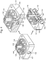
- Fig. 4 shows the heat exchanger system in more detail, and illustrates the base 131 of the servovalve 100 in isolation with various components of the heat exchanger system, as well as the ceramic columns 144.
- the heat exchanger system comprises an inlet 152 that forms the entrance to a first passage 154 within the base 131 of the servovalve 100 the first passage 154 extends from the inlet 152 to an outlet 155 in fluid communication with the pipe 146.
- the outlet 155 is located in an upper surface 133 of the base 131.
- the pipe 146 is formed by a single pipe, but in various embodiments additional pipes may be provided that receive cooling fluid from the first passage 154.
- the pipe 146 could be replaced by a network of pipes.
- the pipe 146 leads to a second passage 156 located within the base 131 which extends from an inlet 158 located in the upper surface 133 of the base 131 to an outlet 150 in fluid communication with the return port 136 of the servovalve 100.
- the inlet 152 of the first passage 154 may be in fluid communication with a source of cooling fluid, for example ambient air.
- the cooling fluid may be drawn through the first passage 154, then the pipe 146 (or network of pipes if applicable) and the second passage 156 by creating suction at the outlet 150 of the second passage 156.
- This section may be created by any suitable means.
- Fig. 5 illustrates an example of one particular means, which utilises the Venturi effect. That is, the second passage 156 is sized such that, upon activation of the servovalve 100 to transfer pneumatic fluid from the inlet port 132 to the return port 136, fluid passing through the return port 136 in the direction of arrows 170 creates a reduced pressure within the second passage 156. This draws the fluid contained within the second passage 156 and, in turn, the pipe 146 and first passage 154 into the flow of fluid passing through the return port 136 as indicated at arrows 172.
- fluid will be transmitted from the source of cooling fluid in fluid communication with the first passage 154 and into the pipe 146 to transfer heat from the base 131 and improve the thermal isolation of the components of the torque motor 120.
- suction will not occur.
- a layer of static cooling air within the pipe 146 may still provide insulation and thermal isolation for the components of the torque motor.
- the central column 139 of the base 131 may be the primary cause of heat transfer from the base 131 (e.g., a main body thereof) to the components of the torque motor 120.
- the insulation elements 140 described above, in particular the third element comprising a heat exchanger system and/or the first and second elements in combination thermal isolation of the torque motor 120 will be improved.
- the embodiments described herein mean that the torque motor 120 of the servovalve 100 is not exposed to high temperatures, or has less exposure to the high temperature of the pneumatic fluid flowing through the servovalve 100.
- the torque motor 120 may stay the same, or substantially similar to those of the prior art whilst incorporating the insulation elements 140 between the torque motor 120 and the base 131 of the servovalve 100.
- the heat exchanger system may be connected to ambient air as the source of cooling fluid, and the means for drawing the cooling fluid through the heat exchanger system may not require substantial amounts of energy (e.g., using the venturi effect as discussed above).
- Fig. 6 shows an exploded, cross-sectional view of the servovalve 100, from which it can be seen that the cap 118 may be secured onto the top surface 119 of the housing 110 using one or more fasteners 218.
- the housing 110 may be located over the torque motor 120 and the insulation elements 140, including the pipe 146 ceramic columns 144 and layer 142 of insulating material. These components then sit on top of the base 131 of the pneumatic section 130, including the supply port 132 control port 134 and return port 136.
Landscapes
- Engineering & Computer Science (AREA)
- General Engineering & Computer Science (AREA)
- Mechanical Engineering (AREA)
- Physics & Mathematics (AREA)
- Thermal Sciences (AREA)
- Fluid Mechanics (AREA)
- Chemical & Material Sciences (AREA)
- Analytical Chemistry (AREA)
- Motor Or Generator Cooling System (AREA)
Abstract
Description
- The present disclosure relates generally to a servovalve, and in particular to a pneumatic servovalve for an aircraft in which a cooling system is employed to isolate the torque motor of the servovalve from high temperatures, for example those that may be received from the supply port of the servovalve.
-
Fig. 1 shows aconventional servovalve 10, which may comprise ahousing 12, atorque motor 14, and apneumatic section 16. - The illustrated
torque motor 14 is a conventional pneumatic torque motor, comprising upper and lowerpermanent magnets 20,electromagnetic coils 22 and anarmature 24. Thearmature 24 is held in place using atorsion bridge 26, which acts to bias thearmature 24 to its resting position as shown inFig. 1 . As is known in the art, upon application of electrical current to theelectromagnetic coils 22, the armature is moved or displaced from its resting position, which movement causes aflapper 28 to move or rotate. - The
pneumatic section 16 of theservovalve 10 comprises abase 30, which comprises asupply port 32, acontrol port 34 and areturn port 36 for pneumatic fluid. Movement of theflapper 28 as described above causes the pneumatic fluid (e.g., air) to move through thepneumatic section 16 from thesupply port 32 to thereturn port 36. - The pneumatic fluid entering the
base 30 of theservovalve 10 is typically very hot, such that the temperature of the supply fluid may be significantly higher than ambient temperature. As such, heat may be transferred from the pneumatic fluid to thetorque motor 14 via part of thebase 30, as indicated byarrows 40. - It is desired to reduce the impact of heat transfer from the
pneumatic section 16 to thetorque motor 14 of theservovalve 10. - In accordance with an aspect of the disclosure, there is provided a heat exchanger system for a servovalve, comprising:
- a base comprising a supply port in fluid communication with a return port, a first passage for fluid connection to a source of cooling fluid, and a second passage in fluid communication with the return port; and
- one or more pipes located adjacent a surface of the base, the one or more pipes fluidly connected between the first passage and the second passage, such that in use cooling fluid may flow from the first passage to the second passage via the one or more pipes.
- The above construction insulates the base of the servovalve and can provide improved cooling for any components that are positioned above (e.g., adjacent to and/or over) the one or more pipes (e.g., the one or more pipes may be located between the base and the components).
- The one or more pipes may be located near to and/or across the surface of the base, such that they are spread over the surface and in close proximity thereto. The surface may be a substantially flat surface configured to support one or more components of a torque motor (e.g., as described below).
- A portion of the pipe or pipes may comprise a substantially flat layer of piping that is spread across the surface of the base and configured to provide a layer of insulation between the base and any components situated over the base and/or fixed to the base.
- The one or more pipes may comprise a labyrinthine pipe or pipes, which may increase the surface area coverage of the pipes across the base.
- The one or more pipes may extend from an outlet of the first passage located in the surface of the base to an inlet of the second passage located in the surface of the base. The inlet and outlet portions of the one or more pipes may extend into or onto the surface of the base. However, it will be appreciated that the majority (e.g., over 90% of the pipes may form the substantially flat layer of piping referred to above.
- The one or more pipes (e.g., the portion comprising the substantially flat layer) may extend substantially parallel to the surface of the base. For example, the longitudinal axis of the one or more pipes in this portion may remain substantially parallel to the surface of the base.
- The one or more pipes may extend over at least 30%, or even 50% of the surface area of the surface of the base, to maximise the cooling ability thereof.
- The one or more pipes may be a single pipe fluidly connected between the first passage and the second passage. Using a single pipe may simplify the construction of the heat exchanger.
- The one or more pipes may be located at least above the supply port. This is commonly where the high heat fluid is passing through the base, and so locating the one or more pipes at least above this feature leads to improved cooling as described herein.
- In accordance with an aspect of the invention there is provided a pneumatic servovalve comprising a heat exchanger system as described in any of the above embodiments.
- The pneumatic servovalve may comprise a torque motor located over a surface of the base, wherein the one or more pipes are located between one or more components of the torque motor and the base. The torque motor may be fixed to the surface of the base (e.g., using one or more fasteners).
- The one or more pipes may be located between one or more components of the torque motor and the base. For example, the one or more pipes may be located at least between a permanent magnet of the torque motor and the base. In a further refinement, the one or more pipes may be located at least between the portion of the base comprising the supply port and a permanent magnet of the torque motor.
- Any aspect or embodiment of a heat exchanger system or pneumatic servovalve as described above may further comprise a layer of thermally insulating material located over (e.g., adjacent to and/or on) the surface of the base. This has been found to further decrease heat transfer from the base to the components of a torque motor positioned thereon.
- This aspect of the disclosure is considered to achieve technical effects in its own right, and may be claimed independently, such that according to an aspect of the disclosure there is provided a pneumatic servovalve comprising:
- a base comprising a supply port in fluid communication with a return port, a first passage for fluid connection to a source of cooling fluid, and a second passage in fluid communication with the return port;
- a torque motor located over a surface of the base; and
- a layer of thermally insulating material located over (e.g., adjacent to and/or on) the surface of the base to thermally insulate one or more components of the torque motor from the base.
- In any of the aspects or embodiments including the layer of thermally insulating material, the layer of thermally insulating material may be configured to rest against a permanent magnet of the torque motor, and/or may be configured to plug one or more gaps (e.g., air gaps) between the components of the torque motor and the base. The layer of thermally insulating material may comprise or consist of mineral wool, for example ceramic fibre wool.
- Additionally, or alternatively, a heat exchanger system or pneumatic servovalve as described above in any aspect or embodiment may further comprise one or more ceramic spacers located on the surface of the base and configured to support one or more components of a torque motor thereon.
- This aspect of the disclosure is considered to achieve technical effects in its own right, and may be claimed independently, such that according to an aspect of the disclosure there is provided a pneumatic servovalve comprising:
- a base comprising a supply port in fluid communication with a return port, a first passage for fluid connection to a source of cooling fluid, and a second passage in fluid communication with the return port;
- a torque motor located over a surface of the base, wherein the torque motor is fastened to the base using one or more fasteners; and
- one or more ceramic columns, each configured to surround a respective one of the fasteners.
- In any of the aspects or embodiments including the ceramic columns, the ceramic columns may comprise tubular members that each fit tightly around a portion of a respective fastener. Each ceramic column may be configured to support a component of the torque motor (e.g., a lower permanent magnet and/or pole piece) thereof.
- In accordance with an aspect of the disclosure, there is provided a method of using a heat exchanger system or pneumatic servovalve as described above, in any aspect or embodiment, wherein the method comprises passing a cooling fluid through the one or more pipes such that cooling fluid flows from the first passage to the second passage via the one or more pipes.
- Various embodiments will now be described, by way of example only, and with reference to the accompanying drawings in which:
-
Fig. 1 shows a conventional arrangement for illustrative purposes only; -
Fig. 2 shows an embodiment of the present disclosure; -
Fig. 3 shows a close-up of part of the embodiment ofFig. 2 ; -
Fig. 4 shows various cross sections of the embodiment ofFig. 2 ; -
Fig. 5 shows a close-up of the embodiment ofFig. 2 illustrating some features of the embodiment in use; and -
Fig. 6 shows an exploded, cross-sectional view of the embodiment ofFig. 2 . - Herewith will be described various embodiments of a servovalve that comprises various features to assist in cooling the servovalve, and specifically a torque motor thereof to mitigate the effects of heat transfer from the high-temperature pneumatic fluid flowing through the servovalve. The servovalve may be used in any suitable application, for example as a servovalve for controlling aircraft working fluid such as engine bleed air or cabin air conditioning.
-
Fig. 2 shows a cross-section of a servovalve 100 according to an embodiment of the present disclosure. Theservovalve 100 comprises ahousing 110, atorque motor 120, apneumatic section 130 and an insulatingsection 140. - The
torque motor 120 may be a conventional torque motor, comprising upper and lowerpermanent magnets 121, one or moreelectromagnetic coils 122, anarmature 123, aflapper 124, and atorsion bridge 125. The upper and lowerpermanent magnets 121 are located either side of thearmature 123, and with theelectromagnetic coils 122 provide a magnetic circuit that can be manipulated by supplying electrical current to theelectromagnetic coils 122. That is, application of an electrical current to theelectromagnetic coils 122 may cause thearmature 123 to pivot against the action of thetorsion bridge 125, which acts to move thearmature 123 into its resting position (as shown inFig. 2 ). Movement of thearmature 123 causes a corresponding movement of theflapper 124, which controls the supply of pneumatic fluid through the servovalve as is known in the art. - The
torque motor 120 is contained within thehousing 110, which extends over and around thetorque motor 120 to protect and isolate the components of thetorque motor 120 in use. In the illustrated embodiment thehousing 110 comprises a plurality ofheat exchanger fins 112 configured to transfer heat from thehousing 110 to the external environment. However, in various embodiments thehousing 110 may be provided withoutheat exchanger fins 112. - A
cap 118 may be provided, which may be located over atop surface 119 of thehousing 110. Thecap 118 may be configured to cover anaperture 117 located in thetop surface 119 of thehousing 110. - The
pneumatic section 130 of theservovalve 100 comprises abase 131, which comprises asupply port 132, acontrol port 134 and areturn port 136 for pneumatic fluid. The base 131 may be comprised of aluminium. Movement of theflapper 124 as described above causes the pneumatic fluid (e.g., air) to move through thepneumatic section 130 from thesupply port 132 to thereturn port 136. - As discussed above the pneumatic fluid passing through the
supply port 132 is typically relatively hot, and heat may be undesirably transferred from the pneumatic fluid through the base 131 as indicated byarrows 40. In order to mitigate or reduce heat transfer to thetorque motor 120 andinsulation elements 140 is provided which comprises a number of parts configured to thermally isolate the components of thetorque motor 120. - The
torque motor 120 may be connected to the base 131 using one ormore fasteners 126. Thefasteners 126 may extend through part of thetorsion bridge 125 and into thebase 131 for securement thereto. Thefasteners 126 may comprise screws that cooperate with a corresponding screw thread within thebase 131. - The base 131 may comprise a
central column 139 that extends in a direction towards thetorque motor 120, and which may be configured to receive theflapper 124 of thetorque motor 120. -
Fig. 3 shows a cross-section of the servovalve 100 oriented at 90 degrees to the cross-section shown inFig. 2 , and showing a close-up of theinsulation elements 140. - The
insulation elements 140 comprise three elements, any or all of which may be included in theservovalve 100 and various embodiments of the present disclosure in order to thermally isolate thetorque motor 120. - A first of the elements is a
layer 142 of insulating material, which may comprise mineral wool, for example ceramic fibre wool. Thelayer 142 of insulating material may extend between aninterior surface 114 of thehousing 110 and anexterior surface 115 of thecentral column 139 of thebase 131. Thelayer 142 may be configured to rest against one of thepermanent magnets 121 of thetorque motor 120, and/or the insulating material in thelayer 142 may be configured to plug one or more gaps (e.g., air gaps) between the components of thetorque motor 120. - The types of mineral wool that can be used may be fire-resistant mineral wool such as ceramic fibre wool or kaowool. The
layer 142 may be formed by sandwiching the mineral wool between aluminium sheets and compressing the sheets together to condense the mineral wool into its desired shape. At this point, the mineral wool may then be inserted into the torque motor during an appropriate stage of construction. - A second of the elements comprises one or more
ceramic columns 144, which may be configured to surround the fasteners of thetorque motor 120 that secure it to thebase 131. Usingceramic columns 144 has been found to provide improved thermal insulation and positioning of thetorque motor 120 when providinginsulation elements 140 as described herein, as well as providing a high compressive strength. It has been found that combining the first and second elements, namely thelayer 142 of insulating material and theceramic columns 144 lead to improvements in the thermal isolation of the components of thetorque motor 120. - A third of the elements comprises a heat exchanger system in the form of a
labyrinthine pipe 146 that is located between thetorque motor 120 and thebase 131 of theservovalve 100. In use a cooling fluid may be transmitted through thepipe 146 such that heat may be transferred from thebase 131 of theservovalve 100 to the fluid within thepipe 146, rather than being transferred to the components of thetorque motor 120. -
Fig. 4 shows the heat exchanger system in more detail, and illustrates thebase 131 of theservovalve 100 in isolation with various components of the heat exchanger system, as well as theceramic columns 144. - The heat exchanger system comprises an
inlet 152 that forms the entrance to afirst passage 154 within thebase 131 of theservovalve 100 thefirst passage 154 extends from theinlet 152 to anoutlet 155 in fluid communication with thepipe 146. Theoutlet 155 is located in anupper surface 133 of thebase 131. In the illustrated embodiment thepipe 146 is formed by a single pipe, but in various embodiments additional pipes may be provided that receive cooling fluid from thefirst passage 154. For example, thepipe 146 could be replaced by a network of pipes. - The
pipe 146 leads to asecond passage 156 located within thebase 131 which extends from aninlet 158 located in theupper surface 133 of the base 131 to anoutlet 150 in fluid communication with thereturn port 136 of theservovalve 100. - The
inlet 152 of thefirst passage 154 may be in fluid communication with a source of cooling fluid, for example ambient air. The cooling fluid may be drawn through thefirst passage 154, then the pipe 146 (or network of pipes if applicable) and thesecond passage 156 by creating suction at theoutlet 150 of thesecond passage 156. This section may be created by any suitable means. -
Fig. 5 illustrates an example of one particular means, which utilises the Venturi effect. That is, thesecond passage 156 is sized such that, upon activation of theservovalve 100 to transfer pneumatic fluid from theinlet port 132 to thereturn port 136, fluid passing through thereturn port 136 in the direction ofarrows 170 creates a reduced pressure within thesecond passage 156. This draws the fluid contained within thesecond passage 156 and, in turn, thepipe 146 andfirst passage 154 into the flow of fluid passing through thereturn port 136 as indicated atarrows 172. - As such, fluid will be transmitted from the source of cooling fluid in fluid communication with the
first passage 154 and into thepipe 146 to transfer heat from thebase 131 and improve the thermal isolation of the components of thetorque motor 120. Using this venturi method, from time to time, for example if thereturn port 136 is closed, suction will not occur. However, even if there is reduced or no suction, a layer of static cooling air within thepipe 146 may still provide insulation and thermal isolation for the components of the torque motor. - It should be noted that the
central column 139 of the base 131 may be the primary cause of heat transfer from the base 131 (e.g., a main body thereof) to the components of thetorque motor 120. However, by using one or more of theinsulation elements 140 described above, in particular the third element comprising a heat exchanger system and/or the first and second elements in combination, thermal isolation of thetorque motor 120 will be improved. The embodiments described herein mean that thetorque motor 120 of theservovalve 100 is not exposed to high temperatures, or has less exposure to the high temperature of the pneumatic fluid flowing through theservovalve 100. In addition, thetorque motor 120 may stay the same, or substantially similar to those of the prior art whilst incorporating theinsulation elements 140 between thetorque motor 120 and thebase 131 of theservovalve 100. In various embodiments the heat exchanger system may be connected to ambient air as the source of cooling fluid, and the means for drawing the cooling fluid through the heat exchanger system may not require substantial amounts of energy (e.g., using the venturi effect as discussed above). -
Fig. 6 shows an exploded, cross-sectional view of theservovalve 100, from which it can be seen that thecap 118 may be secured onto thetop surface 119 of thehousing 110 using one ormore fasteners 218. Thehousing 110 may be located over thetorque motor 120 and theinsulation elements 140, including thepipe 146ceramic columns 144 andlayer 142 of insulating material. These components then sit on top of thebase 131 of thepneumatic section 130, including thesupply port 132control port 134 and returnport 136. - Although the present disclosure has been described with reference to various embodiments, it will be understood by those skilled in the art that various changes in form and detail may be made without departing from the scope of the invention as set forth in the accompanying claims.
Claims (15)
- A heat exchanger system for a servovalve (100), comprising:a base (131) comprising a supply port (132) in fluid communication with a return port (136), a first passage (154) for fluid connection to a source of cooling fluid, and a second passage (156) in fluid communication with the return port (136); andone or more pipes (146) located adjacent a surface (133) of the base (131), the one or more pipes (146) fluidly connected between the first passage (154) and the second passage (156), such that in use cooling fluid may flow from the first passage (154) to the second passage (156) via the one or more pipes (146).
- A heat exchanger system as claimed in claim 1, wherein the one or more pipes (146) comprise a labyrinthine pipe or pipes (146).
- A heat exchanger system as claimed in claim 1 or 2, wherein the one or more pipes (146) extend from an outlet (155) of the first passage located in the surface (133) of the base (131) to an inlet of the second passage (156) located in the surface (133) of the base (131).
- A heat exchanger system as claimed in claim 1, 2 or 3, wherein the one or more pipes (146) extend substantially parallel to the surface (133) of the base (131).
- A heat exchanger system as claimed in claim 4, wherein a longitudinal axis of the one or more pipes (146) extends substantially parallel to the surface (133) of the base (131).
- A heat exchanger system as claimed in any preceding claim, wherein the one or more pipes (146) extend over at least 30% of the surface area of the surface (133) of the base (131).
- A heat exchanger system as claimed in claim 6, wherein the one or more pipes (146) extend over at least 50% of the surface area of the surface (133) of the base (131).
- A heat exchanger system as claimed in any preceding claim, wherein the one or more pipes (146) is a single pipe fluidly connected between the first passage (154) and the second passage (156).
- A heat exchanger system as claimed in any preceding claim, wherein the one or more pipes (146) are located at least above the supply port (132).
- A pneumatic servovalve (100) comprising the heat exchanger system as claimed in any preceding claim.
- A pneumatic servovalve as claimed in claim 10, comprising a torque motor (120) located over a surface (133) of the base (131), wherein the one or more pipes (146) are located between one or more components of the torque motor (120) and the base (131).
- A pneumatic servovalve as claimed in claim 11, wherein the one or more pipes (146) are located between a permanent magnet (121) of the torque motor (120) and the base (131).
- A heat exchanger system or pneumatic servovalve as claimed in any preceding claim, further comprising a layer (142) of thermally insulating material located over the surface (133) of the base (131).
- A heat exchanger system or pneumatic servovalve as claimed in any preceding claim, further comprising one or more ceramic spacers (144) located on the surface (133) of the base (131) and configured to support one or more components of a torque motor (120) thereon.
- A method of using the heat exchanger system or pneumatic servovalve as claimed in any preceding claim, the method comprising:
passing a cooling fluid through the one or more pipes (146) such that cooling fluid flows from the first passage (154) to the second passage (156) via the one or more pipes (146).
Priority Applications (3)
| Application Number | Priority Date | Filing Date | Title |
|---|---|---|---|
| EP18461586.2A EP3597938B1 (en) | 2018-07-20 | 2018-07-20 | Servovalve |
| US16/433,405 US10962143B2 (en) | 2018-07-20 | 2019-06-06 | Servovalve |
| US17/186,147 US11454335B2 (en) | 2018-07-20 | 2021-02-26 | Servovalve |
Applications Claiming Priority (1)
| Application Number | Priority Date | Filing Date | Title |
|---|---|---|---|
| EP18461586.2A EP3597938B1 (en) | 2018-07-20 | 2018-07-20 | Servovalve |
Publications (2)
| Publication Number | Publication Date |
|---|---|
| EP3597938A1 true EP3597938A1 (en) | 2020-01-22 |
| EP3597938B1 EP3597938B1 (en) | 2021-09-22 |
Family
ID=63036002
Family Applications (1)
| Application Number | Title | Priority Date | Filing Date |
|---|---|---|---|
| EP18461586.2A Active EP3597938B1 (en) | 2018-07-20 | 2018-07-20 | Servovalve |
Country Status (2)
| Country | Link |
|---|---|
| US (2) | US10962143B2 (en) |
| EP (1) | EP3597938B1 (en) |
Families Citing this family (15)
| Publication number | Priority date | Publication date | Assignee | Title |
|---|---|---|---|---|
| US10914412B2 (en) | 2018-06-28 | 2021-02-09 | Watts Regulator Co. | Backflow prevention assembly having a variable lay-length and orientation |
| EP3597938B1 (en) | 2018-07-20 | 2021-09-22 | Hamilton Sundstrand Corporation | Servovalve |
| FR3087375B1 (en) * | 2018-10-19 | 2022-01-14 | Commissariat Energie Atomique | INSTRUMENT TOOLS BY FUNCTIONALIZED ADDITIVE MANUFACTURING |
| EP3705866B1 (en) | 2019-03-08 | 2023-09-20 | WATTS INDUSTRIES ITALIA S.r.l. | Differential pressure sensor with magnetic dial |
| USD944366S1 (en) | 2019-03-08 | 2022-02-22 | Watts Industries Italia S.R.L. | Static balancing valve |
| WO2020217127A1 (en) * | 2019-04-24 | 2020-10-29 | Alcon Inc. | Valve cooling and noise suppression |
| US11795666B2 (en) | 2019-05-08 | 2023-10-24 | Watts Regulator Co. | Wireless communication system within a mechanical room |
| US11815424B2 (en) | 2019-05-08 | 2023-11-14 | Watts Regulator Co. | Backflow prevention system test cock with a fluid sensor |
| US12195954B2 (en) | 2019-12-10 | 2025-01-14 | Watts Regulator Co. | System for monitoring backflow preventer condition |
| EP3835494A1 (en) * | 2019-12-10 | 2021-06-16 | Watts Regulator Co. | System for monitoring backflow preventer condition |
| US11585076B2 (en) | 2020-01-24 | 2023-02-21 | Watts Regulator Co. | Apparatus and method for valve cartridge extraction |
| US11719352B2 (en) | 2020-08-17 | 2023-08-08 | Watts Regulator Co. | Check cover assemblies for backflow prevention assemblies with integrated test cock protection shroud |
| US11773992B2 (en) | 2020-08-17 | 2023-10-03 | Watts Regulator Co. | Backflow prevention assembly with a linkage |
| US11739507B2 (en) | 2020-12-09 | 2023-08-29 | Watts Regulator Co. | Test cock with integrated extraction tool |
| USD1021000S1 (en) | 2021-08-17 | 2024-04-02 | Watts Regulator Co. | Valve assembly and body for same |
Citations (6)
| Publication number | Priority date | Publication date | Assignee | Title |
|---|---|---|---|---|
| EP0387533A2 (en) * | 1989-03-13 | 1990-09-19 | Hitachi, Ltd. | Direct-operated servo valve, fluid pressure servo mechanism and control method for the direct-operated servo valve |
| JPH06235404A (en) * | 1993-02-09 | 1994-08-23 | Mitsubishi Heavy Ind Ltd | Fluid pressure servo valve |
| WO2000034119A1 (en) * | 1998-11-26 | 2000-06-15 | Ab Volvo Penta | Hydraulic system in a boat hull, preferably a boat hull having an outboard drive |
| FR2980250A1 (en) * | 2011-09-21 | 2013-03-22 | Snecma | SERVOVALVE WITH REFRIGERATION CIRCUIT |
| CN103615431A (en) * | 2013-12-04 | 2014-03-05 | 中国航空工业第六一八研究所 | Heat dissipation torque motor cover used for hydraulic actuator servo valve |
| EP3045709A1 (en) * | 2015-01-19 | 2016-07-20 | Hamilton Sundstrand Corporation | Valve system comprising a heat exchanger and method of cooling a valve controller |
Family Cites Families (6)
| Publication number | Priority date | Publication date | Assignee | Title |
|---|---|---|---|---|
| US2889815A (en) * | 1956-07-20 | 1959-06-09 | Westinghouse Electric Corp | Pressure feedback servo valve |
| US6413601B1 (en) * | 1998-10-23 | 2002-07-02 | Graftech Inc. | Thermal insulating device |
| US9151130B2 (en) * | 2012-02-02 | 2015-10-06 | Cameron International Corporation | System for controlling temperature of subsea equipment |
| US9255737B2 (en) * | 2012-05-02 | 2016-02-09 | Jhonny Ramon Ramirez Dala | External insulation system for tanks and the like |
| US9328839B2 (en) * | 2014-01-08 | 2016-05-03 | Honeywell International Inc. | High-temperature torque motor actuator |
| EP3597938B1 (en) | 2018-07-20 | 2021-09-22 | Hamilton Sundstrand Corporation | Servovalve |
-
2018
- 2018-07-20 EP EP18461586.2A patent/EP3597938B1/en active Active
-
2019
- 2019-06-06 US US16/433,405 patent/US10962143B2/en active Active
-
2021
- 2021-02-26 US US17/186,147 patent/US11454335B2/en active Active
Patent Citations (6)
| Publication number | Priority date | Publication date | Assignee | Title |
|---|---|---|---|---|
| EP0387533A2 (en) * | 1989-03-13 | 1990-09-19 | Hitachi, Ltd. | Direct-operated servo valve, fluid pressure servo mechanism and control method for the direct-operated servo valve |
| JPH06235404A (en) * | 1993-02-09 | 1994-08-23 | Mitsubishi Heavy Ind Ltd | Fluid pressure servo valve |
| WO2000034119A1 (en) * | 1998-11-26 | 2000-06-15 | Ab Volvo Penta | Hydraulic system in a boat hull, preferably a boat hull having an outboard drive |
| FR2980250A1 (en) * | 2011-09-21 | 2013-03-22 | Snecma | SERVOVALVE WITH REFRIGERATION CIRCUIT |
| CN103615431A (en) * | 2013-12-04 | 2014-03-05 | 中国航空工业第六一八研究所 | Heat dissipation torque motor cover used for hydraulic actuator servo valve |
| EP3045709A1 (en) * | 2015-01-19 | 2016-07-20 | Hamilton Sundstrand Corporation | Valve system comprising a heat exchanger and method of cooling a valve controller |
Also Published As
| Publication number | Publication date |
|---|---|
| US20200025309A1 (en) | 2020-01-23 |
| US10962143B2 (en) | 2021-03-30 |
| EP3597938B1 (en) | 2021-09-22 |
| US20210180722A1 (en) | 2021-06-17 |
| US11454335B2 (en) | 2022-09-27 |
Similar Documents
| Publication | Publication Date | Title |
|---|---|---|
| US11454335B2 (en) | Servovalve | |
| US7478761B2 (en) | Self-contained ventilation flow control system | |
| US9365279B2 (en) | Fuselage of an aircraft or spacecraft and method of actively insulating such a fuselage | |
| US9328839B2 (en) | High-temperature torque motor actuator | |
| EP2808256B1 (en) | Heat exchanger bypass arrangement and valve assembly | |
| US20150122351A1 (en) | Control valve for installing on an internal combustion engine | |
| US10100729B2 (en) | Cooling device for electro-pneumatic controller | |
| US11306842B2 (en) | ACCV and a method for manufacturing the same | |
| CN104595036A (en) | Thermal protection device for equipment in a engine compartment of a turbine engine | |
| EP3187717A1 (en) | Tube thermal coupling assembly | |
| US9945292B2 (en) | Thermoelectric cooled torque motor | |
| US8292259B2 (en) | Magnetic valve | |
| US20080265196A1 (en) | Valves including an insulating member and methods of manufacture | |
| EP3190325B1 (en) | Heating of solenoids | |
| CN112539293A (en) | Plug-in type electromagnetic valve for attitude and orbit control of spaceflight | |
| US11821328B2 (en) | Porous regulator with integrated ventilation | |
| RU2469926C1 (en) | Device for automatic temperature control in spacesuit for outer space operation | |
| US11879448B2 (en) | Electromagnetic actuator | |
| CN211372660U (en) | Air conditioner capable of directly taking heat and cooling | |
| US10072768B1 (en) | Thermo-stratified, passive-cooled servo valve | |
| CN202733160U (en) | Cooling and heat-insulating device of high-temperature electric regulation valve | |
| CN205383013U (en) | Valve device | |
| JP2008060026A (en) | In-furnace induction heating system | |
| JPS60260778A (en) | Solenoid valve | |
| CN114483322A (en) | Aeroengine starts bleed device with temperature compensation function |
Legal Events
| Date | Code | Title | Description |
|---|---|---|---|
| PUAI | Public reference made under article 153(3) epc to a published international application that has entered the european phase |
Free format text: ORIGINAL CODE: 0009012 |
|
| STAA | Information on the status of an ep patent application or granted ep patent |
Free format text: STATUS: THE APPLICATION HAS BEEN PUBLISHED |
|
| AK | Designated contracting states |
Kind code of ref document: A1 Designated state(s): AL AT BE BG CH CY CZ DE DK EE ES FI FR GB GR HR HU IE IS IT LI LT LU LV MC MK MT NL NO PL PT RO RS SE SI SK SM TR |
|
| AX | Request for extension of the european patent |
Extension state: BA ME |
|
| STAA | Information on the status of an ep patent application or granted ep patent |
Free format text: STATUS: REQUEST FOR EXAMINATION WAS MADE |
|
| 17P | Request for examination filed |
Effective date: 20200721 |
|
| RBV | Designated contracting states (corrected) |
Designated state(s): AL AT BE BG CH CY CZ DE DK EE ES FI FR GB GR HR HU IE IS IT LI LT LU LV MC MK MT NL NO PL PT RO RS SE SI SK SM TR |
|
| RIC1 | Information provided on ipc code assigned before grant |
Ipc: F15B 21/04 20190101ALI20210303BHEP Ipc: F28F 9/00 20060101ALI20210303BHEP Ipc: F16K 31/06 20060101ALI20210303BHEP Ipc: F16K 49/00 20060101ALI20210303BHEP Ipc: F15B 13/043 20060101AFI20210303BHEP |
|
| GRAP | Despatch of communication of intention to grant a patent |
Free format text: ORIGINAL CODE: EPIDOSNIGR1 |
|
| STAA | Information on the status of an ep patent application or granted ep patent |
Free format text: STATUS: GRANT OF PATENT IS INTENDED |
|
| INTG | Intention to grant announced |
Effective date: 20210413 |
|
| RAP3 | Party data changed (applicant data changed or rights of an application transferred) |
Owner name: HAMILTON SUNDSTRAND CORPORATION |
|
| GRAS | Grant fee paid |
Free format text: ORIGINAL CODE: EPIDOSNIGR3 |
|
| GRAA | (expected) grant |
Free format text: ORIGINAL CODE: 0009210 |
|
| STAA | Information on the status of an ep patent application or granted ep patent |
Free format text: STATUS: THE PATENT HAS BEEN GRANTED |
|
| AK | Designated contracting states |
Kind code of ref document: B1 Designated state(s): AL AT BE BG CH CY CZ DE DK EE ES FI FR GB GR HR HU IE IS IT LI LT LU LV MC MK MT NL NO PL PT RO RS SE SI SK SM TR |
|
| REG | Reference to a national code |
Ref country code: GB Ref legal event code: FG4D |
|
| REG | Reference to a national code |
Ref country code: DE Ref legal event code: R096 Ref document number: 602018023874 Country of ref document: DE |
|
| REG | Reference to a national code |
Ref country code: IE Ref legal event code: FG4D |
|
| REG | Reference to a national code |
Ref country code: CH Ref legal event code: EP Ref country code: AT Ref legal event code: REF Ref document number: 1432547 Country of ref document: AT Kind code of ref document: T Effective date: 20211015 |
|
| REG | Reference to a national code |
Ref country code: LT Ref legal event code: MG9D |
|
| REG | Reference to a national code |
Ref country code: NL Ref legal event code: MP Effective date: 20210922 |
|
| PG25 | Lapsed in a contracting state [announced via postgrant information from national office to epo] |
Ref country code: NO Free format text: LAPSE BECAUSE OF FAILURE TO SUBMIT A TRANSLATION OF THE DESCRIPTION OR TO PAY THE FEE WITHIN THE PRESCRIBED TIME-LIMIT Effective date: 20211222 Ref country code: BG Free format text: LAPSE BECAUSE OF FAILURE TO SUBMIT A TRANSLATION OF THE DESCRIPTION OR TO PAY THE FEE WITHIN THE PRESCRIBED TIME-LIMIT Effective date: 20211222 Ref country code: LT Free format text: LAPSE BECAUSE OF FAILURE TO SUBMIT A TRANSLATION OF THE DESCRIPTION OR TO PAY THE FEE WITHIN THE PRESCRIBED TIME-LIMIT Effective date: 20210922 Ref country code: SE Free format text: LAPSE BECAUSE OF FAILURE TO SUBMIT A TRANSLATION OF THE DESCRIPTION OR TO PAY THE FEE WITHIN THE PRESCRIBED TIME-LIMIT Effective date: 20210922 Ref country code: RS Free format text: LAPSE BECAUSE OF FAILURE TO SUBMIT A TRANSLATION OF THE DESCRIPTION OR TO PAY THE FEE WITHIN THE PRESCRIBED TIME-LIMIT Effective date: 20210922 Ref country code: FI Free format text: LAPSE BECAUSE OF FAILURE TO SUBMIT A TRANSLATION OF THE DESCRIPTION OR TO PAY THE FEE WITHIN THE PRESCRIBED TIME-LIMIT Effective date: 20210922 Ref country code: HR Free format text: LAPSE BECAUSE OF FAILURE TO SUBMIT A TRANSLATION OF THE DESCRIPTION OR TO PAY THE FEE WITHIN THE PRESCRIBED TIME-LIMIT Effective date: 20210922 |
|
| REG | Reference to a national code |
Ref country code: AT Ref legal event code: MK05 Ref document number: 1432547 Country of ref document: AT Kind code of ref document: T Effective date: 20210922 |
|
| PG25 | Lapsed in a contracting state [announced via postgrant information from national office to epo] |
Ref country code: LV Free format text: LAPSE BECAUSE OF FAILURE TO SUBMIT A TRANSLATION OF THE DESCRIPTION OR TO PAY THE FEE WITHIN THE PRESCRIBED TIME-LIMIT Effective date: 20210922 Ref country code: GR Free format text: LAPSE BECAUSE OF FAILURE TO SUBMIT A TRANSLATION OF THE DESCRIPTION OR TO PAY THE FEE WITHIN THE PRESCRIBED TIME-LIMIT Effective date: 20211223 |
|
| PG25 | Lapsed in a contracting state [announced via postgrant information from national office to epo] |
Ref country code: AT Free format text: LAPSE BECAUSE OF FAILURE TO SUBMIT A TRANSLATION OF THE DESCRIPTION OR TO PAY THE FEE WITHIN THE PRESCRIBED TIME-LIMIT Effective date: 20210922 |
|
| PG25 | Lapsed in a contracting state [announced via postgrant information from national office to epo] |
Ref country code: IS Free format text: LAPSE BECAUSE OF FAILURE TO SUBMIT A TRANSLATION OF THE DESCRIPTION OR TO PAY THE FEE WITHIN THE PRESCRIBED TIME-LIMIT Effective date: 20220122 Ref country code: SK Free format text: LAPSE BECAUSE OF FAILURE TO SUBMIT A TRANSLATION OF THE DESCRIPTION OR TO PAY THE FEE WITHIN THE PRESCRIBED TIME-LIMIT Effective date: 20210922 Ref country code: RO Free format text: LAPSE BECAUSE OF FAILURE TO SUBMIT A TRANSLATION OF THE DESCRIPTION OR TO PAY THE FEE WITHIN THE PRESCRIBED TIME-LIMIT Effective date: 20210922 Ref country code: PT Free format text: LAPSE BECAUSE OF FAILURE TO SUBMIT A TRANSLATION OF THE DESCRIPTION OR TO PAY THE FEE WITHIN THE PRESCRIBED TIME-LIMIT Effective date: 20220124 Ref country code: PL Free format text: LAPSE BECAUSE OF FAILURE TO SUBMIT A TRANSLATION OF THE DESCRIPTION OR TO PAY THE FEE WITHIN THE PRESCRIBED TIME-LIMIT Effective date: 20210922 Ref country code: NL Free format text: LAPSE BECAUSE OF FAILURE TO SUBMIT A TRANSLATION OF THE DESCRIPTION OR TO PAY THE FEE WITHIN THE PRESCRIBED TIME-LIMIT Effective date: 20210922 Ref country code: ES Free format text: LAPSE BECAUSE OF FAILURE TO SUBMIT A TRANSLATION OF THE DESCRIPTION OR TO PAY THE FEE WITHIN THE PRESCRIBED TIME-LIMIT Effective date: 20210922 Ref country code: EE Free format text: LAPSE BECAUSE OF FAILURE TO SUBMIT A TRANSLATION OF THE DESCRIPTION OR TO PAY THE FEE WITHIN THE PRESCRIBED TIME-LIMIT Effective date: 20210922 Ref country code: CZ Free format text: LAPSE BECAUSE OF FAILURE TO SUBMIT A TRANSLATION OF THE DESCRIPTION OR TO PAY THE FEE WITHIN THE PRESCRIBED TIME-LIMIT Effective date: 20210922 Ref country code: AL Free format text: LAPSE BECAUSE OF FAILURE TO SUBMIT A TRANSLATION OF THE DESCRIPTION OR TO PAY THE FEE WITHIN THE PRESCRIBED TIME-LIMIT Effective date: 20210922 |
|
| REG | Reference to a national code |
Ref country code: DE Ref legal event code: R097 Ref document number: 602018023874 Country of ref document: DE |
|
| PG25 | Lapsed in a contracting state [announced via postgrant information from national office to epo] |
Ref country code: DK Free format text: LAPSE BECAUSE OF FAILURE TO SUBMIT A TRANSLATION OF THE DESCRIPTION OR TO PAY THE FEE WITHIN THE PRESCRIBED TIME-LIMIT Effective date: 20210922 |
|
| PLBE | No opposition filed within time limit |
Free format text: ORIGINAL CODE: 0009261 |
|
| STAA | Information on the status of an ep patent application or granted ep patent |
Free format text: STATUS: NO OPPOSITION FILED WITHIN TIME LIMIT |
|
| 26N | No opposition filed |
Effective date: 20220623 |
|
| PG25 | Lapsed in a contracting state [announced via postgrant information from national office to epo] |
Ref country code: SI Free format text: LAPSE BECAUSE OF FAILURE TO SUBMIT A TRANSLATION OF THE DESCRIPTION OR TO PAY THE FEE WITHIN THE PRESCRIBED TIME-LIMIT Effective date: 20210922 |
|
| PG25 | Lapsed in a contracting state [announced via postgrant information from national office to epo] |
Ref country code: IT Free format text: LAPSE BECAUSE OF FAILURE TO SUBMIT A TRANSLATION OF THE DESCRIPTION OR TO PAY THE FEE WITHIN THE PRESCRIBED TIME-LIMIT Effective date: 20210922 |
|
| PG25 | Lapsed in a contracting state [announced via postgrant information from national office to epo] |
Ref country code: MC Free format text: LAPSE BECAUSE OF FAILURE TO SUBMIT A TRANSLATION OF THE DESCRIPTION OR TO PAY THE FEE WITHIN THE PRESCRIBED TIME-LIMIT Effective date: 20210922 |
|
| REG | Reference to a national code |
Ref country code: CH Ref legal event code: PL |
|
| REG | Reference to a national code |
Ref country code: BE Ref legal event code: MM Effective date: 20220731 |
|
| PG25 | Lapsed in a contracting state [announced via postgrant information from national office to epo] |
Ref country code: LU Free format text: LAPSE BECAUSE OF NON-PAYMENT OF DUE FEES Effective date: 20220720 Ref country code: LI Free format text: LAPSE BECAUSE OF NON-PAYMENT OF DUE FEES Effective date: 20220731 Ref country code: CH Free format text: LAPSE BECAUSE OF NON-PAYMENT OF DUE FEES Effective date: 20220731 |
|
| PG25 | Lapsed in a contracting state [announced via postgrant information from national office to epo] |
Ref country code: BE Free format text: LAPSE BECAUSE OF NON-PAYMENT OF DUE FEES Effective date: 20220731 |
|
| P01 | Opt-out of the competence of the unified patent court (upc) registered |
Effective date: 20230522 |
|
| PG25 | Lapsed in a contracting state [announced via postgrant information from national office to epo] |
Ref country code: IE Free format text: LAPSE BECAUSE OF NON-PAYMENT OF DUE FEES Effective date: 20220720 |
|
| PG25 | Lapsed in a contracting state [announced via postgrant information from national office to epo] |
Ref country code: HU Free format text: LAPSE BECAUSE OF FAILURE TO SUBMIT A TRANSLATION OF THE DESCRIPTION OR TO PAY THE FEE WITHIN THE PRESCRIBED TIME-LIMIT; INVALID AB INITIO Effective date: 20180720 |
|
| PG25 | Lapsed in a contracting state [announced via postgrant information from national office to epo] |
Ref country code: SM Free format text: LAPSE BECAUSE OF FAILURE TO SUBMIT A TRANSLATION OF THE DESCRIPTION OR TO PAY THE FEE WITHIN THE PRESCRIBED TIME-LIMIT Effective date: 20210922 Ref country code: MK Free format text: LAPSE BECAUSE OF FAILURE TO SUBMIT A TRANSLATION OF THE DESCRIPTION OR TO PAY THE FEE WITHIN THE PRESCRIBED TIME-LIMIT Effective date: 20210922 Ref country code: CY Free format text: LAPSE BECAUSE OF FAILURE TO SUBMIT A TRANSLATION OF THE DESCRIPTION OR TO PAY THE FEE WITHIN THE PRESCRIBED TIME-LIMIT Effective date: 20210922 |
|
| PG25 | Lapsed in a contracting state [announced via postgrant information from national office to epo] |
Ref country code: MT Free format text: LAPSE BECAUSE OF FAILURE TO SUBMIT A TRANSLATION OF THE DESCRIPTION OR TO PAY THE FEE WITHIN THE PRESCRIBED TIME-LIMIT Effective date: 20210922 |
|
| PGFP | Annual fee paid to national office [announced via postgrant information from national office to epo] |
Ref country code: GB Payment date: 20250619 Year of fee payment: 8 |
|
| PGFP | Annual fee paid to national office [announced via postgrant information from national office to epo] |
Ref country code: FR Payment date: 20250620 Year of fee payment: 8 |
|
| PGFP | Annual fee paid to national office [announced via postgrant information from national office to epo] |
Ref country code: DE Payment date: 20250620 Year of fee payment: 8 |
|
| PG25 | Lapsed in a contracting state [announced via postgrant information from national office to epo] |
Ref country code: TR Free format text: LAPSE BECAUSE OF FAILURE TO SUBMIT A TRANSLATION OF THE DESCRIPTION OR TO PAY THE FEE WITHIN THE PRESCRIBED TIME-LIMIT Effective date: 20210922 |