EP3597930A1 - Cam isolation system for gas turbine engine compressor section - Google Patents
Cam isolation system for gas turbine engine compressor section Download PDFInfo
- Publication number
- EP3597930A1 EP3597930A1 EP19175251.8A EP19175251A EP3597930A1 EP 3597930 A1 EP3597930 A1 EP 3597930A1 EP 19175251 A EP19175251 A EP 19175251A EP 3597930 A1 EP3597930 A1 EP 3597930A1
- Authority
- EP
- European Patent Office
- Prior art keywords
- bracket
- cam
- actuator
- slot
- gas turbine
- Prior art date
- Legal status (The legal status is an assumption and is not a legal conclusion. Google has not performed a legal analysis and makes no representation as to the accuracy of the status listed.)
- Granted
Links
Images

Classifications
-
- F—MECHANICAL ENGINEERING; LIGHTING; HEATING; WEAPONS; BLASTING
- F04—POSITIVE - DISPLACEMENT MACHINES FOR LIQUIDS; PUMPS FOR LIQUIDS OR ELASTIC FLUIDS
- F04D—NON-POSITIVE-DISPLACEMENT PUMPS
- F04D29/00—Details, component parts, or accessories
- F04D29/40—Casings; Connections of working fluid
- F04D29/52—Casings; Connections of working fluid for axial pumps
- F04D29/54—Fluid-guiding means, e.g. diffusers
- F04D29/56—Fluid-guiding means, e.g. diffusers adjustable
- F04D29/563—Fluid-guiding means, e.g. diffusers adjustable specially adapted for elastic fluid pumps
-
- F—MECHANICAL ENGINEERING; LIGHTING; HEATING; WEAPONS; BLASTING
- F01—MACHINES OR ENGINES IN GENERAL; ENGINE PLANTS IN GENERAL; STEAM ENGINES
- F01D—NON-POSITIVE DISPLACEMENT MACHINES OR ENGINES, e.g. STEAM TURBINES
- F01D17/00—Regulating or controlling by varying flow
- F01D17/10—Final actuators
- F01D17/12—Final actuators arranged in stator parts
- F01D17/14—Final actuators arranged in stator parts varying effective cross-sectional area of nozzles or guide conduits
- F01D17/16—Final actuators arranged in stator parts varying effective cross-sectional area of nozzles or guide conduits by means of nozzle vanes
- F01D17/162—Final actuators arranged in stator parts varying effective cross-sectional area of nozzles or guide conduits by means of nozzle vanes for axial flow, i.e. the vanes turning around axes which are essentially perpendicular to the rotor centre line
-
- F—MECHANICAL ENGINEERING; LIGHTING; HEATING; WEAPONS; BLASTING
- F01—MACHINES OR ENGINES IN GENERAL; ENGINE PLANTS IN GENERAL; STEAM ENGINES
- F01D—NON-POSITIVE DISPLACEMENT MACHINES OR ENGINES, e.g. STEAM TURBINES
- F01D25/00—Component parts, details, or accessories, not provided for in, or of interest apart from, other groups
- F01D25/28—Supporting or mounting arrangements, e.g. for turbine casing
-
- F—MECHANICAL ENGINEERING; LIGHTING; HEATING; WEAPONS; BLASTING
- F05—INDEXING SCHEMES RELATING TO ENGINES OR PUMPS IN VARIOUS SUBCLASSES OF CLASSES F01-F04
- F05B—INDEXING SCHEME RELATING TO WIND, SPRING, WEIGHT, INERTIA OR LIKE MOTORS, TO MACHINES OR ENGINES FOR LIQUIDS COVERED BY SUBCLASSES F03B, F03D AND F03G
- F05B2260/00—Function
- F05B2260/50—Kinematic linkage, i.e. transmission of position
-
- F—MECHANICAL ENGINEERING; LIGHTING; HEATING; WEAPONS; BLASTING
- F05—INDEXING SCHEMES RELATING TO ENGINES OR PUMPS IN VARIOUS SUBCLASSES OF CLASSES F01-F04
- F05D—INDEXING SCHEME FOR ASPECTS RELATING TO NON-POSITIVE-DISPLACEMENT MACHINES OR ENGINES, GAS-TURBINES OR JET-PROPULSION PLANTS
- F05D2220/00—Application
- F05D2220/30—Application in turbines
- F05D2220/32—Application in turbines in gas turbines
-
- Y—GENERAL TAGGING OF NEW TECHNOLOGICAL DEVELOPMENTS; GENERAL TAGGING OF CROSS-SECTIONAL TECHNOLOGIES SPANNING OVER SEVERAL SECTIONS OF THE IPC; TECHNICAL SUBJECTS COVERED BY FORMER USPC CROSS-REFERENCE ART COLLECTIONS [XRACs] AND DIGESTS
- Y02—TECHNOLOGIES OR APPLICATIONS FOR MITIGATION OR ADAPTATION AGAINST CLIMATE CHANGE
- Y02T—CLIMATE CHANGE MITIGATION TECHNOLOGIES RELATED TO TRANSPORTATION
- Y02T50/00—Aeronautics or air transport
- Y02T50/60—Efficient propulsion technologies, e.g. for aircraft
Definitions
- Exemplary embodiments pertain to the art of gas turbine engines and, more particularly, to a cam isolation system of a compressor section for such gas turbine engines.
- OLE airfoils on leading edge (OLE) airfoils to axial compressor gas turbine engine technology has enhancements related to compressor efficiency, leading to increased thrust and fuel efficiency.
- OLE airfoils also drastically increase the surge loading experienced by the actuation system responsible for turning the airfoils. This is due to the center of pressure on the airfoil being farther away from a trunnion, or rotating axis of the airfoil. While the linkage system capability is being pushed to its limits, resolving the load out where the actuator is attached to the engine outer case may exceed material capability.
- the outer split cases of jet engines are now being driven to composite materials that are not as strong as conventional titanium. Combined with the higher surge loads, this threatens pushing the engine outer case back to titanium, which would lead to an undesirable massive weight gain.
- the system includes a torque tube.
- the system also includes a cam bracket operatively coupled to an engine case structure, the cam bracket defining a slot.
- the system further includes an actuator bracket operatively coupled to the torque tube at a first end of the actuator bracket, the actuator bracket having a pin disposed within the slot of the cam bracket.
- further embodiments may include that the engine case structure is formed of a composite material.
- cam bracket includes a first cam bracket side and a second cam bracket side, the first cam bracket side defining a first slot and the second cam bracket side defining a second slot, the actuator bracket having a first pin extending from a first side of the actuator bracket and into the first slot, the actuator bracket having a second pin extending from a second side of the actuator bracket and into the second slot.
- further embodiments may include that the first pin and the second pin are integrally formed with the actuator bracket.
- actuator bracket is not directly coupled to the engine case structure.
- further embodiments may include that the pin is disposed within the slot for movement within the slot during a surge event of the gas turbine engine compressor section.
- further embodiments may include that disposal of the pin within the slot prevents radial and tangential vibration of the actuator bracket.
- cam bracket is bolted to the engine case structure.
- a gas turbine engine including a compressor section, a combustor section, and a turbine section.
- the gas turbine engine also includes a variable vane actuator assembly for the compressor section.
- the variable vane actuator assembly includes a torque tube operatively coupled to a variable vane mechanism.
- the variable vane actuator assembly also includes a cam bracket operatively coupled to an engine case structure.
- the variable vane actuator assembly further includes an actuator bracket operatively coupled to the torque tube at a first end of the actuator bracket, the actuator bracket operatively coupled to the cam bracket at a second end of the actuator bracket, the actuator bracket not directly coupled to engine case structure.
- further embodiments may include that the engine case structure is formed of a composite material.
- cam bracket includes a first cam bracket side and a second cam bracket side, the first cam bracket side defining a first slot and the second cam bracket side defining a second slot, the actuator bracket having a first pin extending from a first side of the actuator bracket and into the first slot, the actuator bracket having a second pin extending from a second side of the actuator bracket and into the second slot.
- further embodiments may include that the first pin and the second pin are integrally formed with the actuator bracket.
- further embodiments may include that the pins are disposed in the slots for movement within the slots during a surge event of the compressor section.
- further embodiments may include that disposal of the pins within the slots prevents radial and tangential vibration of the actuator bracket.
- cam bracket is bolted to the engine case structure.
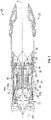
- FIG. 1 schematically illustrates a gas turbine engine 20.
- the gas turbine engine 20 is disclosed herein as a two-spool turbofan that generally incorporates a fan section 22, a compressor section 24, a combustor section 26, a turbine section 28, an augmenter section 30 and a nozzle section 32.
- the sections are defined along a central longitudinal engine axis A.
- FIG. 1 schematically illustrates a gas turbine engine 20.
- the gas turbine engine 20 is disclosed herein as a two-spool turbofan that generally incorporates a fan section 22, a compressor section 24, a combustor section 26, a turbine section 28, an augmenter section 30 and a nozzle section 32.
- the sections are defined along a central longitudinal engine axis A.
- FIG. 1 schematically illustrates a gas turbine engine 20.
- the gas turbine engine 20 is disclosed herein as a two-spool turbofan that generally incorporates a fan section 22, a compressor section 24, a combustor section 26, a turbine section 28, an augmenter section 30 and
- the compressor section 24, the combustor section 26 and the turbine section 28 are generally referred to as the engine core.
- the fan section 22 and a low pressure turbine 34 of the turbine section 28 are coupled by a first shaft 36 to define a low spool.
- the compressor section 24 and a high pressure turbine 38 of the turbine section 28 are coupled by a second shaft 40 to define a high spool.
- An outer engine case structure 42 and an inner engine structure 44 define a generally annular secondary flow path 46 around a core flow path 48 of the engine core. It should be understood that various structure within the engine may define the outer engine case structure 42 and the inner engine structure 44 which essentially define an exoskeleton to support the core engine therein.
- Air which enters the fan section 22 is divided between a core flow through the core flow path 48 and a secondary flow through the secondary flow path 46.
- the core flow passes through the combustor section 26, the turbine section 28, then the augmentor section 30 where fuel may be selectively injected and burned to generate additional thrust through the nozzle section 32.
- the secondary flow may be utilized for a multiple of purposes to include, for example, cooling and pressurization.
- the secondary flow as defined herein is any flow different from the primary combustion gas exhaust core flow.
- the secondary flow passes through an annulus defined by the outer engine case structure 42 and the inner engine structure 44 then may be at least partially injected into the core flow adjacent the nozzle section 32.
- a radial flow separation wall 72 is configured to separate a first flow path FP1 of the gas turbine engine 20 from a second flow path FP2 of the gas turbine engine 20.
- the first flow path FP1 flows through blades of the gas turbine engine 20 and the second flow path FP2 flows through guide vanes, also referred to as stators, of the gas turbine engine 20.
- the first flow path FP1 may be the core flow path 48 and the second flow path FP2 may be the secondary flow path. It is understood that embodiments disclosed herein are also applicable to gas turbine engines with more than two flow paths.
- the radial flow separation wall 72 may be composed of one or more components of the gas turbine engine 20.
- variable vane actuator assembly 50 for the compressor section 24 is illustrated.
- the variable vane actuator assembly 50 may also be referred to as a cam isolation system, as the variable vane actuator assembly 50 dissociates surge loads experienced by the compressor section 24 from the outer engine case structure 42, as will be appreciated from the disclosure herein.
- the outer engine case structure 42 is a composite material. By dissociating the compressor surge loads from the outer engine case structure 42, the structure 42 may remain composite and provide the beneficial weight savings associated with the composite, when compared to other materials, such as titanium.
- the variable vane actuator assembly 50 includes a torque tube 52 that is operatively coupled to a variable vane mechanism (not shown) that transfers forces to one or more variable vanes to impart movement of the vane(s).
- the torque tube 52 is disposed within an aperture 54 of an actuator bracket 56.
- the aperture 54 of the actuator bracket 56 is located proximate a first end 58 of the actuator bracket 56.
- the torque tube 52 includes an outer end 60 that extends through, and out of, the aperture 54 of the actuator bracket 56.
- a mount spherical 62 provides an interface between the torque tube 52 and the actuator bracket 56.
- the actuator bracket 56 includes a second end 64 that provides an actuator mounting location 68 for coupling of an actuator (not shown) thereto.
- the actuator extends between the actuator mounting location 68 and the torque tube 52 for transfer of a load to the torque tube 52 along a load path L.
- the load on the torque tube 52 actuates movement of the variable vane(s).
- the actuator bracket 56 includes a first pin 70 extending outwardly in a first direction from a main body portion 72 of the actuator bracket 56 and a second pin 74 extending outwardly from the main body portion 72 in a second direction that is opposite to that of the first direction.
- the first pin 70 and the second pin 74 are integrally formed with the actuator bracket 56.
- the variable vane actuator assembly 50 also includes a cam bracket 80 that is operatively coupled to the outer engine case structure 42.
- the cam bracket 80 is directly coupled to the outer engine case structure 42 with mechanical fasteners, such as bolts 81 or the like.
- the cam bracket 80 includes a cam base 82 that is the portion of the cam bracket 80 that is coupled to the outer engine case structure 42. Extending outwardly from the cam base is a first cam bracket side 84 and a second cam bracket side 86.
- the first and second cam bracket sides 84, 86 are spaced from each other to define a cam bracket space 88.
- the first cam bracket side 84 defines a first slot 90 and the second cam bracket side 86 defines a second slot 92.
- a portion of the actuator bracket 56 that is proximate the second end 64 of the actuator bracket 56 is disposed within the cam bracket space 88.
- the first pin 70 of the actuator bracket 56 is disposed within the first slot 90 and the second pin 74 of the actuator bracket 56 is disposed within the second slot 92.
- the actuator bracket 56 disclosed herein is decoupled from the outer engine case structure 42 in a manner that allows relative movement between the actuator bracket 56 and the outer engine case structure 42. This is due to the cam bracket slots 90, 92 that accommodate translation of the pins 70, 74 of the actuator bracket 56 therein. This is particularly beneficial during surge load events experienced by the compressor section 24. In such events, the surge loads are not transferred to the outer engine case structure 42. This is important for outer engine case structures that are formed of composite.
- Coupling of the actuator bracket 56 to the cam bracket 80 in the above-described manner also prevents the actuator bracket 56 from experiencing engine radial and tangential vibratory modes that may otherwise cause the bracket to fail in high-cycle fatigue, and also to provide the necessary constraints to ensure accuracy between the actuator stroke and effector output.
- the actuator bracket coupling locations now put less parts in loading and will lead to more predictable deflection and engine behavior. Without the embodiments described herein, a significantly stronger, and heavier, material (e.g., titanium) would have to be utilized for the outer engine case structure 42.
Landscapes
- Engineering & Computer Science (AREA)
- Mechanical Engineering (AREA)
- General Engineering & Computer Science (AREA)
- Structures Of Non-Positive Displacement Pumps (AREA)
Abstract
Description
- Exemplary embodiments pertain to the art of gas turbine engines and, more particularly, to a cam isolation system of a compressor section for such gas turbine engines.
- The advent of on leading edge (OLE) airfoils to axial compressor gas turbine engine technology has enhancements related to compressor efficiency, leading to increased thrust and fuel efficiency. However, OLE airfoils also drastically increase the surge loading experienced by the actuation system responsible for turning the airfoils. This is due to the center of pressure on the airfoil being farther away from a trunnion, or rotating axis of the airfoil. While the linkage system capability is being pushed to its limits, resolving the load out where the actuator is attached to the engine outer case may exceed material capability. Driven by lower temperatures and large volume, the outer split cases of jet engines are now being driven to composite materials that are not as strong as conventional titanium. Combined with the higher surge loads, this threatens pushing the engine outer case back to titanium, which would lead to an undesirable massive weight gain.
- Disclosed is a cam isolation system for a gas turbine engine compressor actuator. The system includes a torque tube. The system also includes a cam bracket operatively coupled to an engine case structure, the cam bracket defining a slot. The system further includes an actuator bracket operatively coupled to the torque tube at a first end of the actuator bracket, the actuator bracket having a pin disposed within the slot of the cam bracket.
- In addition to one or more of the features described above, or as an alternative, further embodiments may include that the engine case structure is formed of a composite material.
- In addition to one or more of the features described above, or as an alternative, further embodiments may include that the cam bracket includes a first cam bracket side and a second cam bracket side, the first cam bracket side defining a first slot and the second cam bracket side defining a second slot, the actuator bracket having a first pin extending from a first side of the actuator bracket and into the first slot, the actuator bracket having a second pin extending from a second side of the actuator bracket and into the second slot.
- In addition to one or more of the features described above, or as an alternative, further embodiments may include that the first pin and the second pin are integrally formed with the actuator bracket.
- In addition to one or more of the features described above, or as an alternative, further embodiments may include that the actuator bracket is not directly coupled to the engine case structure.
- In addition to one or more of the features described above, or as an alternative, further embodiments may include that the pin is disposed within the slot for movement within the slot during a surge event of the gas turbine engine compressor section.
- In addition to one or more of the features described above, or as an alternative, further embodiments may include that disposal of the pin within the slot prevents radial and tangential vibration of the actuator bracket.
- In addition to one or more of the features described above, or as an alternative, further embodiments may include that the cam bracket is bolted to the engine case structure.
- Also disclosed is a gas turbine engine including a compressor section, a combustor section, and a turbine section. The gas turbine engine also includes a variable vane actuator assembly for the compressor section. The variable vane actuator assembly includes a torque tube operatively coupled to a variable vane mechanism. The variable vane actuator assembly also includes a cam bracket operatively coupled to an engine case structure. The variable vane actuator assembly further includes an actuator bracket operatively coupled to the torque tube at a first end of the actuator bracket, the actuator bracket operatively coupled to the cam bracket at a second end of the actuator bracket, the actuator bracket not directly coupled to engine case structure.
- In addition to one or more of the features described above, or as an alternative, further embodiments may include that the engine case structure is formed of a composite material.
- In addition to one or more of the features described above, or as an alternative, further embodiments may include that the cam bracket includes a first cam bracket side and a second cam bracket side, the first cam bracket side defining a first slot and the second cam bracket side defining a second slot, the actuator bracket having a first pin extending from a first side of the actuator bracket and into the first slot, the actuator bracket having a second pin extending from a second side of the actuator bracket and into the second slot.
- In addition to one or more of the features described above, or as an alternative, further embodiments may include that the first pin and the second pin are integrally formed with the actuator bracket.
- In addition to one or more of the features described above, or as an alternative, further embodiments may include that the pins are disposed in the slots for movement within the slots during a surge event of the compressor section.
- In addition to one or more of the features described above, or as an alternative, further embodiments may include that disposal of the pins within the slots prevents radial and tangential vibration of the actuator bracket.
- In addition to one or more of the features described above, or as an alternative, further embodiments may include that the cam bracket is bolted to the engine case structure.
- The foregoing features and elements may be combined in various combinations without exclusivity, unless expressly indicated otherwise. These features and elements as well as the operation thereof will become more apparent in light of the following description and the accompanying drawings. It should be understood, however, that the following description and drawings are intended to be illustrative and explanatory in nature and non-limiting.
- The following descriptions should not be considered limiting in any way. With reference to the accompanying drawings, like elements are numbered alike:
-
FIG. 1 is a partial cross-sectional view of a gas turbine engine; -
FIG. 2 is a side elevational view of a cam isolation system for a compressor section of the gas turbine engine; and -
FIG. 3 is an end view of the cam isolation system. - A detailed description of one or more embodiments of the disclosed apparatus and method are presented herein by way of exemplification and not limitation with reference to the Figures.
-
FIG. 1 schematically illustrates agas turbine engine 20. Thegas turbine engine 20 is disclosed herein as a two-spool turbofan that generally incorporates afan section 22, acompressor section 24, acombustor section 26, aturbine section 28, anaugmenter section 30 and anozzle section 32. The sections are defined along a central longitudinal engine axis A. Although depicted as an augmented low bypass gas turbine engine in the disclosed non-limiting embodiment, it should be understood that the concepts described herein are applicable to other gas turbine engines including geared architecture engines, direct drive turbofans, turboshaft engines and others. - The
compressor section 24, thecombustor section 26 and theturbine section 28 are generally referred to as the engine core. Thefan section 22 and alow pressure turbine 34 of theturbine section 28 are coupled by afirst shaft 36 to define a low spool. Thecompressor section 24 and ahigh pressure turbine 38 of theturbine section 28 are coupled by asecond shaft 40 to define a high spool. - An outer
engine case structure 42 and aninner engine structure 44 define a generally annularsecondary flow path 46 around acore flow path 48 of the engine core. It should be understood that various structure within the engine may define the outerengine case structure 42 and theinner engine structure 44 which essentially define an exoskeleton to support the core engine therein. - Air which enters the
fan section 22 is divided between a core flow through thecore flow path 48 and a secondary flow through thesecondary flow path 46. The core flow passes through thecombustor section 26, theturbine section 28, then theaugmentor section 30 where fuel may be selectively injected and burned to generate additional thrust through thenozzle section 32. The secondary flow may be utilized for a multiple of purposes to include, for example, cooling and pressurization. The secondary flow as defined herein is any flow different from the primary combustion gas exhaust core flow. The secondary flow passes through an annulus defined by the outerengine case structure 42 and theinner engine structure 44 then may be at least partially injected into the core flow adjacent thenozzle section 32. - A radial
flow separation wall 72 is configured to separate a first flow path FP1 of thegas turbine engine 20 from a second flow path FP2 of thegas turbine engine 20. The first flow path FP1 flows through blades of thegas turbine engine 20 and the second flow path FP2 flows through guide vanes, also referred to as stators, of thegas turbine engine 20. The first flow path FP1 may be thecore flow path 48 and the second flow path FP2 may be the secondary flow path. It is understood that embodiments disclosed herein are also applicable to gas turbine engines with more than two flow paths. The radialflow separation wall 72 may be composed of one or more components of thegas turbine engine 20. - Referring now to
FIGS. 2 and 3 , a variablevane actuator assembly 50 for thecompressor section 24 is illustrated. The variablevane actuator assembly 50 may also be referred to as a cam isolation system, as the variablevane actuator assembly 50 dissociates surge loads experienced by thecompressor section 24 from the outerengine case structure 42, as will be appreciated from the disclosure herein. The outerengine case structure 42 is a composite material. By dissociating the compressor surge loads from the outerengine case structure 42, thestructure 42 may remain composite and provide the beneficial weight savings associated with the composite, when compared to other materials, such as titanium. - The variable
vane actuator assembly 50 includes atorque tube 52 that is operatively coupled to a variable vane mechanism (not shown) that transfers forces to one or more variable vanes to impart movement of the vane(s). Thetorque tube 52 is disposed within anaperture 54 of anactuator bracket 56. Theaperture 54 of theactuator bracket 56 is located proximate afirst end 58 of theactuator bracket 56. Thetorque tube 52 includes anouter end 60 that extends through, and out of, theaperture 54 of theactuator bracket 56. A mount spherical 62 provides an interface between thetorque tube 52 and theactuator bracket 56. Theactuator bracket 56 includes asecond end 64 that provides anactuator mounting location 68 for coupling of an actuator (not shown) thereto. The actuator extends between theactuator mounting location 68 and thetorque tube 52 for transfer of a load to thetorque tube 52 along a load path L. The load on thetorque tube 52 actuates movement of the variable vane(s). - The
actuator bracket 56 includes afirst pin 70 extending outwardly in a first direction from amain body portion 72 of theactuator bracket 56 and asecond pin 74 extending outwardly from themain body portion 72 in a second direction that is opposite to that of the first direction. In some embodiments, thefirst pin 70 and thesecond pin 74 are integrally formed with theactuator bracket 56. - The variable
vane actuator assembly 50 also includes acam bracket 80 that is operatively coupled to the outerengine case structure 42. In some embodiments, thecam bracket 80 is directly coupled to the outerengine case structure 42 with mechanical fasteners, such asbolts 81 or the like. Thecam bracket 80 includes acam base 82 that is the portion of thecam bracket 80 that is coupled to the outerengine case structure 42. Extending outwardly from the cam base is a first cam bracket side 84 and a secondcam bracket side 86. The first and second cam bracket sides 84, 86 are spaced from each other to define acam bracket space 88. The first cam bracket side 84 defines afirst slot 90 and the secondcam bracket side 86 defines asecond slot 92. - A portion of the
actuator bracket 56 that is proximate thesecond end 64 of theactuator bracket 56 is disposed within thecam bracket space 88. Thefirst pin 70 of theactuator bracket 56 is disposed within thefirst slot 90 and thesecond pin 74 of theactuator bracket 56 is disposed within thesecond slot 92. - Rather than having the
actuator bracket 56 rigidly fixed to the outer engine case structure 42 - whether with direct coupling or inflexible indirect coupling - theactuator bracket 56 disclosed herein is decoupled from the outerengine case structure 42 in a manner that allows relative movement between theactuator bracket 56 and the outerengine case structure 42. This is due to thecam bracket slots pins actuator bracket 56 therein. This is particularly beneficial during surge load events experienced by thecompressor section 24. In such events, the surge loads are not transferred to the outerengine case structure 42. This is important for outer engine case structures that are formed of composite. - Coupling of the
actuator bracket 56 to thecam bracket 80 in the above-described manner also prevents theactuator bracket 56 from experiencing engine radial and tangential vibratory modes that may otherwise cause the bracket to fail in high-cycle fatigue, and also to provide the necessary constraints to ensure accuracy between the actuator stroke and effector output. The actuator bracket coupling locations now put less parts in loading and will lead to more predictable deflection and engine behavior. Without the embodiments described herein, a significantly stronger, and heavier, material (e.g., titanium) would have to be utilized for the outerengine case structure 42. - The term "about" is intended to include the degree of error associated with measurement of the particular quantity based upon the equipment available at the time of filing the application. For example, "about" can include a range of ± 8% or 5%, or 2% of a given value.
- The terminology used herein is for the purpose of describing particular embodiments only and is not intended to be limiting of the present disclosure. As used herein, the singular forms "a", "an" and "the" are intended to include the plural forms as well, unless the context clearly indicates otherwise. It will be further understood that the terms "comprises" and/or "comprising," when used in this specification, specify the presence of stated features, integers, steps, operations, elements, and/or components, but do not preclude the presence or addition of one or more other features, integers, steps, operations, element components, and/or groups thereof.
- While the present disclosure has been described with reference to an exemplary embodiment or embodiments, it will be understood by those skilled in the art that various changes may be made and equivalents may be substituted for elements thereof without departing from the scope of the present disclosure. In addition, many modifications may be made to adapt a particular situation or material to the teachings of the present disclosure without departing from the scope thereof. Therefore, it is intended that the present disclosure not be limited to the particular embodiment disclosed as the best mode contemplated for carrying out this present disclosure, but that the present disclosure will include all embodiments falling within the scope of the claims.
Claims (15)
- A cam isolation system (50) for a gas turbine engine (20) compressor actuator comprising:a torque tube (52);a cam bracket (80) operatively coupled to an engine case structure (42), the cam bracket defining a slot (90, 92); andan actuator bracket (56) operatively coupled to the torque tube at a first end (58) of the actuator bracket, the actuator bracket having a pin (70, 74) disposed within the slot of the cam bracket.
- The cam isolation system (50) of claim 1, wherein the engine case structure (42) is formed of a composite material.
- The cam isolation system (50) of claim 1 or 2, wherein the cam bracket (80) includes a first cam bracket side (84) and a second cam bracket side (86), the first cam bracket side defining a first slot (90) and the second cam bracket side defining a second slot (92), the actuator bracket having a first pin (70) extending from a first side of the actuator bracket (56) and into the first slot, the actuator bracket having a second pin (74) extending from a second side of the actuator bracket and into the second slot.
- The cam isolation system (50) of claim 3, wherein the first pin (70) and the second pin (74) are integrally formed with the actuator bracket (56).
- The cam isolation system (50) of any preceding claim, wherein the actuator bracket (56) is not directly coupled to the engine case structure (42).
- The cam isolation system (50) of any preceding claim, wherein the pin (70, 74) is disposed within the slot (90, 92) for movement within the slot during a surge event of the gas turbine engine (20) compressor section (24).
- The cam isolation system (50) of any preceding claim, wherein disposal of the pin (70, 74) within the slot (90, 92) prevents radial and tangential vibration of the actuator bracket (56).
- The cam isolation system (50) of any preceding claim, wherein the cam bracket (56) is bolted to the engine case structure (42).
- A gas turbine engine (20) comprising:a compressor section (24);a combustor section (26);a turbine section (28); anda variable vane actuator assembly (50) for the compressor section (24), the variable vane actuator assembly comprising:a torque tube (52) operatively coupled to a variable vane mechanism;a cam bracket (80) operatively coupled to an engine case structure (42); andan actuator bracket (56) operatively coupled to the torque tube at a first end (58) of the actuator bracket, the actuator bracket operatively coupled to the cam bracket at a second end (64) of the actuator bracket, the actuator bracket not directly coupled to engine case structure.
- The gas turbine engine (20) of claim 9, wherein the engine case structure (42) is formed of a composite material.
- The gas turbine engine (20) of claim 9 or 10, wherein the cam bracket (80) includes a first cam bracket side (84) and a second cam bracket side (86), the first cam bracket side defining a first slot (90) and the second cam bracket side defining a second slot (92), the actuator bracket having a first pin (70) extending from a first side of the actuator bracket (56) and into the first slot, the actuator bracket having a second pin (74) extending from a second side of the actuator bracket and into the second slot.
- The gas turbine engine (20) of claim 11, wherein the first pin (70) and the second pin (74) are integrally formed with the actuator bracket (56).
- The gas turbine engine (20) of claim 11 or 12, wherein the pins (70, 74) are disposed in the slots (90, 92) for movement within the slots during a surge event of the compressor section (24).
- The gas turbine engine (20) of claim 11, 12 or 13, wherein disposal of the pins (70, 74) within the slots (90, 92) prevents radial and tangential vibration of the actuator bracket (56).
- The gas turbine engine (20) of any of claims 9 to 14, wherein the cam bracket (80) is bolted to the engine case structure (42).
Applications Claiming Priority (1)
| Application Number | Priority Date | Filing Date | Title |
|---|---|---|---|
| US16/038,344 US10830086B2 (en) | 2018-07-18 | 2018-07-18 | Cam isolation system for gas turbine engine compressor section |
Publications (2)
| Publication Number | Publication Date |
|---|---|
| EP3597930A1 true EP3597930A1 (en) | 2020-01-22 |
| EP3597930B1 EP3597930B1 (en) | 2022-12-21 |
Family
ID=66625022
Family Applications (1)
| Application Number | Title | Priority Date | Filing Date |
|---|---|---|---|
| EP19175251.8A Active EP3597930B1 (en) | 2018-07-18 | 2019-05-17 | Cam isolation system for gas turbine engine compressor section |
Country Status (2)
| Country | Link |
|---|---|
| US (1) | US10830086B2 (en) |
| EP (1) | EP3597930B1 (en) |
Citations (5)
| Publication number | Priority date | Publication date | Assignee | Title |
|---|---|---|---|---|
| US3873230A (en) * | 1974-04-10 | 1975-03-25 | United Aircraft Corp | Stator vane actuating mechanism |
| US4720237A (en) * | 1986-02-24 | 1988-01-19 | United Technologies Corporation | Unison ring actuator assembly |
| EP1387041A2 (en) * | 2002-07-31 | 2004-02-04 | General Electric Company | Stator vane actuator in gas turbine engine |
| US20110033297A1 (en) * | 2008-04-24 | 2011-02-10 | Michael Andre Bouru | Device for controlling variable-pitch blades in a turbomachine compressor |
| US20140133968A1 (en) * | 2012-11-15 | 2014-05-15 | United Technologies Corporation | Bellcrank for a variable vane assembly |
Family Cites Families (6)
| Publication number | Priority date | Publication date | Assignee | Title |
|---|---|---|---|---|
| GB1105926A (en) | 1965-06-09 | 1968-03-13 | Gen Electric | Improvements in systems for controlling windmilling of gas turbine engines of multi-engined aircraft |
| US4834613A (en) | 1988-02-26 | 1989-05-30 | United Technologies Corporation | Radially constrained variable vane shroud |
| FR2928979B1 (en) * | 2008-03-19 | 2015-05-01 | Snecma | DEVICE FOR CONTROLLING AUBES WITH VARIABLE TIMING IN A TURBOMACHINE. |
| US9091209B2 (en) * | 2012-06-20 | 2015-07-28 | United Technologies Corporation | Four bar bracket |
| US20140050580A1 (en) | 2012-08-14 | 2014-02-20 | Weaver Wind Energy | Wind turbine with actuating tail and method of operation |
| BE1024982B1 (en) * | 2017-02-09 | 2018-09-10 | Safran Aero Boosters Sa | TURBOMACHINE COMPRESSOR WITH AUBES WITH VARIABLE SHIFT |
-
2018
- 2018-07-18 US US16/038,344 patent/US10830086B2/en active Active
-
2019
- 2019-05-17 EP EP19175251.8A patent/EP3597930B1/en active Active
Patent Citations (5)
| Publication number | Priority date | Publication date | Assignee | Title |
|---|---|---|---|---|
| US3873230A (en) * | 1974-04-10 | 1975-03-25 | United Aircraft Corp | Stator vane actuating mechanism |
| US4720237A (en) * | 1986-02-24 | 1988-01-19 | United Technologies Corporation | Unison ring actuator assembly |
| EP1387041A2 (en) * | 2002-07-31 | 2004-02-04 | General Electric Company | Stator vane actuator in gas turbine engine |
| US20110033297A1 (en) * | 2008-04-24 | 2011-02-10 | Michael Andre Bouru | Device for controlling variable-pitch blades in a turbomachine compressor |
| US20140133968A1 (en) * | 2012-11-15 | 2014-05-15 | United Technologies Corporation | Bellcrank for a variable vane assembly |
Also Published As
| Publication number | Publication date |
|---|---|
| EP3597930B1 (en) | 2022-12-21 |
| US20200025023A1 (en) | 2020-01-23 |
| US10830086B2 (en) | 2020-11-10 |
Similar Documents
| Publication | Publication Date | Title |
|---|---|---|
| EP2971599B1 (en) | Variable vane drive system | |
| US20140234085A1 (en) | Bushing arranged between a body and a shaft, and connected to the shaft | |
| CN116209821B (en) | Turbine module provided with propeller and offset stator blades | |
| EP3502497A1 (en) | Flexible preloaded ball bearing assembly | |
| US11236634B2 (en) | Turbine engine outer shroud | |
| CN114687863A (en) | Turbine rear frame link assembly for turbofan engine | |
| US11933219B2 (en) | Stator configuration for gas turbine engine | |
| EP3051062B1 (en) | Gas turbine alignment tie rod device and method of utilization | |
| EP3282101B1 (en) | Shim for gas turbine engine | |
| EP3597930B1 (en) | Cam isolation system for gas turbine engine compressor section | |
| EP3693558B1 (en) | Shear locking bumper for gas turbine engine | |
| US12044167B2 (en) | Stator configuration for gas turbine engine | |
| US11851158B2 (en) | Variable pitch fan assembly with remote counterweights | |
| EP3421739B1 (en) | Gas turbine duct liner coupling assembly | |
| US10619649B2 (en) | Bellcrank assembly for gas turbine engine and method | |
| US12467383B2 (en) | Joint for connection to variable guide vane of gas turbine engine | |
| EP4571054A1 (en) | Outer air seal (oas) with improved mating with first stage casing | |
| EP3214277B1 (en) | Systems for stiffening cases on gas-turbine engines |
Legal Events
| Date | Code | Title | Description |
|---|---|---|---|
| PUAI | Public reference made under article 153(3) epc to a published international application that has entered the european phase |
Free format text: ORIGINAL CODE: 0009012 |
|
| STAA | Information on the status of an ep patent application or granted ep patent |
Free format text: STATUS: THE APPLICATION HAS BEEN PUBLISHED |
|
| AK | Designated contracting states |
Kind code of ref document: A1 Designated state(s): AL AT BE BG CH CY CZ DE DK EE ES FI FR GB GR HR HU IE IS IT LI LT LU LV MC MK MT NL NO PL PT RO RS SE SI SK SM TR |
|
| AX | Request for extension of the european patent |
Extension state: BA ME |
|
| STAA | Information on the status of an ep patent application or granted ep patent |
Free format text: STATUS: REQUEST FOR EXAMINATION WAS MADE |
|
| 17P | Request for examination filed |
Effective date: 20200721 |
|
| RBV | Designated contracting states (corrected) |
Designated state(s): AL AT BE BG CH CY CZ DE DK EE ES FI FR GB GR HR HU IE IS IT LI LT LU LV MC MK MT NL NO PL PT RO RS SE SI SK SM TR |
|
| RAP1 | Party data changed (applicant data changed or rights of an application transferred) |
Owner name: RAYTHEON TECHNOLOGIES CORPORATION |
|
| GRAP | Despatch of communication of intention to grant a patent |
Free format text: ORIGINAL CODE: EPIDOSNIGR1 |
|
| STAA | Information on the status of an ep patent application or granted ep patent |
Free format text: STATUS: GRANT OF PATENT IS INTENDED |
|
| INTG | Intention to grant announced |
Effective date: 20220629 |
|
| GRAS | Grant fee paid |
Free format text: ORIGINAL CODE: EPIDOSNIGR3 |
|
| GRAA | (expected) grant |
Free format text: ORIGINAL CODE: 0009210 |
|
| STAA | Information on the status of an ep patent application or granted ep patent |
Free format text: STATUS: THE PATENT HAS BEEN GRANTED |
|
| AK | Designated contracting states |
Kind code of ref document: B1 Designated state(s): AL AT BE BG CH CY CZ DE DK EE ES FI FR GB GR HR HU IE IS IT LI LT LU LV MC MK MT NL NO PL PT RO RS SE SI SK SM TR |
|
| REG | Reference to a national code |
Ref country code: GB Ref legal event code: FG4D |
|
| REG | Reference to a national code |
Ref country code: CH Ref legal event code: EP |
|
| REG | Reference to a national code |
Ref country code: DE Ref legal event code: R096 Ref document number: 602019023313 Country of ref document: DE |
|
| REG | Reference to a national code |
Ref country code: AT Ref legal event code: REF Ref document number: 1539215 Country of ref document: AT Kind code of ref document: T Effective date: 20230115 |
|
| REG | Reference to a national code |
Ref country code: IE Ref legal event code: FG4D |
|
| REG | Reference to a national code |
Ref country code: LT Ref legal event code: MG9D |
|
| REG | Reference to a national code |
Ref country code: NL Ref legal event code: MP Effective date: 20221221 |
|
| PG25 | Lapsed in a contracting state [announced via postgrant information from national office to epo] |
Ref country code: SE Free format text: LAPSE BECAUSE OF FAILURE TO SUBMIT A TRANSLATION OF THE DESCRIPTION OR TO PAY THE FEE WITHIN THE PRESCRIBED TIME-LIMIT Effective date: 20221221 Ref country code: NO Free format text: LAPSE BECAUSE OF FAILURE TO SUBMIT A TRANSLATION OF THE DESCRIPTION OR TO PAY THE FEE WITHIN THE PRESCRIBED TIME-LIMIT Effective date: 20230321 Ref country code: LT Free format text: LAPSE BECAUSE OF FAILURE TO SUBMIT A TRANSLATION OF THE DESCRIPTION OR TO PAY THE FEE WITHIN THE PRESCRIBED TIME-LIMIT Effective date: 20221221 Ref country code: FI Free format text: LAPSE BECAUSE OF FAILURE TO SUBMIT A TRANSLATION OF THE DESCRIPTION OR TO PAY THE FEE WITHIN THE PRESCRIBED TIME-LIMIT Effective date: 20221221 |
|
| REG | Reference to a national code |
Ref country code: AT Ref legal event code: MK05 Ref document number: 1539215 Country of ref document: AT Kind code of ref document: T Effective date: 20221221 |
|
| PG25 | Lapsed in a contracting state [announced via postgrant information from national office to epo] |
Ref country code: RS Free format text: LAPSE BECAUSE OF FAILURE TO SUBMIT A TRANSLATION OF THE DESCRIPTION OR TO PAY THE FEE WITHIN THE PRESCRIBED TIME-LIMIT Effective date: 20221221 Ref country code: LV Free format text: LAPSE BECAUSE OF FAILURE TO SUBMIT A TRANSLATION OF THE DESCRIPTION OR TO PAY THE FEE WITHIN THE PRESCRIBED TIME-LIMIT Effective date: 20221221 Ref country code: HR Free format text: LAPSE BECAUSE OF FAILURE TO SUBMIT A TRANSLATION OF THE DESCRIPTION OR TO PAY THE FEE WITHIN THE PRESCRIBED TIME-LIMIT Effective date: 20221221 Ref country code: GR Free format text: LAPSE BECAUSE OF FAILURE TO SUBMIT A TRANSLATION OF THE DESCRIPTION OR TO PAY THE FEE WITHIN THE PRESCRIBED TIME-LIMIT Effective date: 20230322 |
|
| P01 | Opt-out of the competence of the unified patent court (upc) registered |
Effective date: 20230521 |
|
| PG25 | Lapsed in a contracting state [announced via postgrant information from national office to epo] |
Ref country code: NL Free format text: LAPSE BECAUSE OF FAILURE TO SUBMIT A TRANSLATION OF THE DESCRIPTION OR TO PAY THE FEE WITHIN THE PRESCRIBED TIME-LIMIT Effective date: 20221221 |
|
| PG25 | Lapsed in a contracting state [announced via postgrant information from national office to epo] |
Ref country code: SM Free format text: LAPSE BECAUSE OF FAILURE TO SUBMIT A TRANSLATION OF THE DESCRIPTION OR TO PAY THE FEE WITHIN THE PRESCRIBED TIME-LIMIT Effective date: 20221221 Ref country code: RO Free format text: LAPSE BECAUSE OF FAILURE TO SUBMIT A TRANSLATION OF THE DESCRIPTION OR TO PAY THE FEE WITHIN THE PRESCRIBED TIME-LIMIT Effective date: 20221221 Ref country code: PT Free format text: LAPSE BECAUSE OF FAILURE TO SUBMIT A TRANSLATION OF THE DESCRIPTION OR TO PAY THE FEE WITHIN THE PRESCRIBED TIME-LIMIT Effective date: 20230421 Ref country code: ES Free format text: LAPSE BECAUSE OF FAILURE TO SUBMIT A TRANSLATION OF THE DESCRIPTION OR TO PAY THE FEE WITHIN THE PRESCRIBED TIME-LIMIT Effective date: 20221221 Ref country code: EE Free format text: LAPSE BECAUSE OF FAILURE TO SUBMIT A TRANSLATION OF THE DESCRIPTION OR TO PAY THE FEE WITHIN THE PRESCRIBED TIME-LIMIT Effective date: 20221221 Ref country code: CZ Free format text: LAPSE BECAUSE OF FAILURE TO SUBMIT A TRANSLATION OF THE DESCRIPTION OR TO PAY THE FEE WITHIN THE PRESCRIBED TIME-LIMIT Effective date: 20221221 Ref country code: AT Free format text: LAPSE BECAUSE OF FAILURE TO SUBMIT A TRANSLATION OF THE DESCRIPTION OR TO PAY THE FEE WITHIN THE PRESCRIBED TIME-LIMIT Effective date: 20221221 |
|
| PG25 | Lapsed in a contracting state [announced via postgrant information from national office to epo] |
Ref country code: SK Free format text: LAPSE BECAUSE OF FAILURE TO SUBMIT A TRANSLATION OF THE DESCRIPTION OR TO PAY THE FEE WITHIN THE PRESCRIBED TIME-LIMIT Effective date: 20221221 Ref country code: PL Free format text: LAPSE BECAUSE OF FAILURE TO SUBMIT A TRANSLATION OF THE DESCRIPTION OR TO PAY THE FEE WITHIN THE PRESCRIBED TIME-LIMIT Effective date: 20221221 Ref country code: IS Free format text: LAPSE BECAUSE OF FAILURE TO SUBMIT A TRANSLATION OF THE DESCRIPTION OR TO PAY THE FEE WITHIN THE PRESCRIBED TIME-LIMIT Effective date: 20230421 Ref country code: AL Free format text: LAPSE BECAUSE OF FAILURE TO SUBMIT A TRANSLATION OF THE DESCRIPTION OR TO PAY THE FEE WITHIN THE PRESCRIBED TIME-LIMIT Effective date: 20221221 |
|
| REG | Reference to a national code |
Ref country code: DE Ref legal event code: R097 Ref document number: 602019023313 Country of ref document: DE |
|
| PLBE | No opposition filed within time limit |
Free format text: ORIGINAL CODE: 0009261 |
|
| STAA | Information on the status of an ep patent application or granted ep patent |
Free format text: STATUS: NO OPPOSITION FILED WITHIN TIME LIMIT |
|
| PG25 | Lapsed in a contracting state [announced via postgrant information from national office to epo] |
Ref country code: DK Free format text: LAPSE BECAUSE OF FAILURE TO SUBMIT A TRANSLATION OF THE DESCRIPTION OR TO PAY THE FEE WITHIN THE PRESCRIBED TIME-LIMIT Effective date: 20221221 |
|
| RAP4 | Party data changed (patent owner data changed or rights of a patent transferred) |
Owner name: RTX CORPORATION |
|
| 26N | No opposition filed |
Effective date: 20230922 |
|
| REG | Reference to a national code |
Ref country code: CH Ref legal event code: PL |
|
| PG25 | Lapsed in a contracting state [announced via postgrant information from national office to epo] |
Ref country code: MC Free format text: LAPSE BECAUSE OF FAILURE TO SUBMIT A TRANSLATION OF THE DESCRIPTION OR TO PAY THE FEE WITHIN THE PRESCRIBED TIME-LIMIT Effective date: 20221221 |
|
| REG | Reference to a national code |
Ref country code: BE Ref legal event code: MM Effective date: 20230531 |
|
| PG25 | Lapsed in a contracting state [announced via postgrant information from national office to epo] |
Ref country code: SI Free format text: LAPSE BECAUSE OF FAILURE TO SUBMIT A TRANSLATION OF THE DESCRIPTION OR TO PAY THE FEE WITHIN THE PRESCRIBED TIME-LIMIT Effective date: 20221221 Ref country code: MC Free format text: LAPSE BECAUSE OF FAILURE TO SUBMIT A TRANSLATION OF THE DESCRIPTION OR TO PAY THE FEE WITHIN THE PRESCRIBED TIME-LIMIT Effective date: 20221221 Ref country code: LU Free format text: LAPSE BECAUSE OF NON-PAYMENT OF DUE FEES Effective date: 20230517 Ref country code: LI Free format text: LAPSE BECAUSE OF NON-PAYMENT OF DUE FEES Effective date: 20230531 Ref country code: CH Free format text: LAPSE BECAUSE OF NON-PAYMENT OF DUE FEES Effective date: 20230531 |
|
| REG | Reference to a national code |
Ref country code: IE Ref legal event code: MM4A |
|
| PG25 | Lapsed in a contracting state [announced via postgrant information from national office to epo] |
Ref country code: IE Free format text: LAPSE BECAUSE OF NON-PAYMENT OF DUE FEES Effective date: 20230517 |
|
| PG25 | Lapsed in a contracting state [announced via postgrant information from national office to epo] |
Ref country code: IE Free format text: LAPSE BECAUSE OF NON-PAYMENT OF DUE FEES Effective date: 20230517 |
|
| PG25 | Lapsed in a contracting state [announced via postgrant information from national office to epo] |
Ref country code: IT Free format text: LAPSE BECAUSE OF FAILURE TO SUBMIT A TRANSLATION OF THE DESCRIPTION OR TO PAY THE FEE WITHIN THE PRESCRIBED TIME-LIMIT Effective date: 20221221 Ref country code: BE Free format text: LAPSE BECAUSE OF NON-PAYMENT OF DUE FEES Effective date: 20230531 |
|
| PG25 | Lapsed in a contracting state [announced via postgrant information from national office to epo] |
Ref country code: BG Free format text: LAPSE BECAUSE OF FAILURE TO SUBMIT A TRANSLATION OF THE DESCRIPTION OR TO PAY THE FEE WITHIN THE PRESCRIBED TIME-LIMIT Effective date: 20221221 |
|
| PG25 | Lapsed in a contracting state [announced via postgrant information from national office to epo] |
Ref country code: BG Free format text: LAPSE BECAUSE OF FAILURE TO SUBMIT A TRANSLATION OF THE DESCRIPTION OR TO PAY THE FEE WITHIN THE PRESCRIBED TIME-LIMIT Effective date: 20221221 |
|
| PGFP | Annual fee paid to national office [announced via postgrant information from national office to epo] |
Ref country code: DE Payment date: 20250423 Year of fee payment: 7 |
|
| PGFP | Annual fee paid to national office [announced via postgrant information from national office to epo] |
Ref country code: GB Payment date: 20250423 Year of fee payment: 7 |
|
| PGFP | Annual fee paid to national office [announced via postgrant information from national office to epo] |
Ref country code: FR Payment date: 20250423 Year of fee payment: 7 |
|
| PG25 | Lapsed in a contracting state [announced via postgrant information from national office to epo] |
Ref country code: CY Free format text: LAPSE BECAUSE OF FAILURE TO SUBMIT A TRANSLATION OF THE DESCRIPTION OR TO PAY THE FEE WITHIN THE PRESCRIBED TIME-LIMIT; INVALID AB INITIO Effective date: 20190517 |
|
| PG25 | Lapsed in a contracting state [announced via postgrant information from national office to epo] |
Ref country code: HU Free format text: LAPSE BECAUSE OF FAILURE TO SUBMIT A TRANSLATION OF THE DESCRIPTION OR TO PAY THE FEE WITHIN THE PRESCRIBED TIME-LIMIT; INVALID AB INITIO Effective date: 20190517 |
|
| REG | Reference to a national code |
Ref country code: DE Ref legal event code: R081 Ref document number: 602019023313 Country of ref document: DE Owner name: RTX CORPORATION (N.D.GES.D. STAATES DELAWARE),, US Free format text: FORMER OWNER: RAYTHEON TECHNOLOGIES CORPORATION, FARMINGTON, CT, US |
|
| PG25 | Lapsed in a contracting state [announced via postgrant information from national office to epo] |
Ref country code: TR Free format text: LAPSE BECAUSE OF FAILURE TO SUBMIT A TRANSLATION OF THE DESCRIPTION OR TO PAY THE FEE WITHIN THE PRESCRIBED TIME-LIMIT Effective date: 20221221 |