EP3597927B1 - Bleed valve with resonance chamber integrated in the closing member - Google Patents
Bleed valve with resonance chamber integrated in the closing member Download PDFInfo
- Publication number
- EP3597927B1 EP3597927B1 EP19195221.7A EP19195221A EP3597927B1 EP 3597927 B1 EP3597927 B1 EP 3597927B1 EP 19195221 A EP19195221 A EP 19195221A EP 3597927 B1 EP3597927 B1 EP 3597927B1
- Authority
- EP
- European Patent Office
- Prior art keywords
- bleed
- bleed valve
- chamber
- resonator
- duct
- Prior art date
- Legal status (The legal status is an assumption and is not a legal conclusion. Google has not performed a legal analysis and makes no representation as to the accuracy of the status listed.)
- Active
Links
Images




Classifications
-
- F—MECHANICAL ENGINEERING; LIGHTING; HEATING; WEAPONS; BLASTING
- F02—COMBUSTION ENGINES; HOT-GAS OR COMBUSTION-PRODUCT ENGINE PLANTS
- F02C—GAS-TURBINE PLANTS; AIR INTAKES FOR JET-PROPULSION PLANTS; CONTROLLING FUEL SUPPLY IN AIR-BREATHING JET-PROPULSION PLANTS
- F02C9/00—Controlling gas-turbine plants; Controlling fuel supply in air- breathing jet-propulsion plants
- F02C9/16—Control of working fluid flow
- F02C9/18—Control of working fluid flow by bleeding, bypassing or acting on variable working fluid interconnections between turbines or compressors or their stages
-
- F—MECHANICAL ENGINEERING; LIGHTING; HEATING; WEAPONS; BLASTING
- F01—MACHINES OR ENGINES IN GENERAL; ENGINE PLANTS IN GENERAL; STEAM ENGINES
- F01D—NON-POSITIVE DISPLACEMENT MACHINES OR ENGINES, e.g. STEAM TURBINES
- F01D17/00—Regulating or controlling by varying flow
- F01D17/10—Final actuators
- F01D17/105—Final actuators by passing part of the fluid
-
- F—MECHANICAL ENGINEERING; LIGHTING; HEATING; WEAPONS; BLASTING
- F02—COMBUSTION ENGINES; HOT-GAS OR COMBUSTION-PRODUCT ENGINE PLANTS
- F02C—GAS-TURBINE PLANTS; AIR INTAKES FOR JET-PROPULSION PLANTS; CONTROLLING FUEL SUPPLY IN AIR-BREATHING JET-PROPULSION PLANTS
- F02C3/00—Gas-turbine plants characterised by the use of combustion products as the working fluid
- F02C3/04—Gas-turbine plants characterised by the use of combustion products as the working fluid having a turbine driving a compressor
- F02C3/13—Gas-turbine plants characterised by the use of combustion products as the working fluid having a turbine driving a compressor having variable working fluid interconnections between turbines or compressors or stages of different rotors
-
- F—MECHANICAL ENGINEERING; LIGHTING; HEATING; WEAPONS; BLASTING
- F02—COMBUSTION ENGINES; HOT-GAS OR COMBUSTION-PRODUCT ENGINE PLANTS
- F02C—GAS-TURBINE PLANTS; AIR INTAKES FOR JET-PROPULSION PLANTS; CONTROLLING FUEL SUPPLY IN AIR-BREATHING JET-PROPULSION PLANTS
- F02C6/00—Plural gas-turbine plants; Combinations of gas-turbine plants with other apparatus; Adaptations of gas-turbine plants for special use
- F02C6/04—Gas-turbine plants providing heated or pressurised working fluid for other apparatus, e.g. without mechanical power output
- F02C6/06—Gas-turbine plants providing heated or pressurised working fluid for other apparatus, e.g. without mechanical power output providing compressed gas
- F02C6/08—Gas-turbine plants providing heated or pressurised working fluid for other apparatus, e.g. without mechanical power output providing compressed gas the gas being bled from the gas-turbine compressor
-
- F—MECHANICAL ENGINEERING; LIGHTING; HEATING; WEAPONS; BLASTING
- F04—POSITIVE - DISPLACEMENT MACHINES FOR LIQUIDS; PUMPS FOR LIQUIDS OR ELASTIC FLUIDS
- F04D—NON-POSITIVE-DISPLACEMENT PUMPS
- F04D27/00—Control, e.g. regulation, of pumps, pumping installations or pumping systems specially adapted for elastic fluids
- F04D27/02—Surge control
- F04D27/0207—Surge control by bleeding, bypassing or recycling fluids
- F04D27/0215—Arrangements therefor, e.g. bleed or by-pass valves
-
- F—MECHANICAL ENGINEERING; LIGHTING; HEATING; WEAPONS; BLASTING
- F04—POSITIVE - DISPLACEMENT MACHINES FOR LIQUIDS; PUMPS FOR LIQUIDS OR ELASTIC FLUIDS
- F04D—NON-POSITIVE-DISPLACEMENT PUMPS
- F04D27/00—Control, e.g. regulation, of pumps, pumping installations or pumping systems specially adapted for elastic fluids
- F04D27/02—Surge control
- F04D27/0207—Surge control by bleeding, bypassing or recycling fluids
- F04D27/023—Details or means for fluid extraction
-
- F—MECHANICAL ENGINEERING; LIGHTING; HEATING; WEAPONS; BLASTING
- F04—POSITIVE - DISPLACEMENT MACHINES FOR LIQUIDS; PUMPS FOR LIQUIDS OR ELASTIC FLUIDS
- F04D—NON-POSITIVE-DISPLACEMENT PUMPS
- F04D29/00—Details, component parts, or accessories
- F04D29/66—Combating cavitation, whirls, noise, vibration or the like; Balancing
- F04D29/661—Combating cavitation, whirls, noise, vibration or the like; Balancing especially adapted for elastic fluid pumps
- F04D29/663—Sound attenuation
- F04D29/665—Sound attenuation by means of resonance chambers or interference
-
- F—MECHANICAL ENGINEERING; LIGHTING; HEATING; WEAPONS; BLASTING
- F05—INDEXING SCHEMES RELATING TO ENGINES OR PUMPS IN VARIOUS SUBCLASSES OF CLASSES F01-F04
- F05D—INDEXING SCHEME FOR ASPECTS RELATING TO NON-POSITIVE-DISPLACEMENT MACHINES OR ENGINES, GAS-TURBINES OR JET-PROPULSION PLANTS
- F05D2260/00—Function
- F05D2260/30—Retaining components in desired mutual position
- F05D2260/36—Retaining components in desired mutual position by a form fit connection, e.g. by interlocking
-
- F—MECHANICAL ENGINEERING; LIGHTING; HEATING; WEAPONS; BLASTING
- F05—INDEXING SCHEMES RELATING TO ENGINES OR PUMPS IN VARIOUS SUBCLASSES OF CLASSES F01-F04
- F05D—INDEXING SCHEME FOR ASPECTS RELATING TO NON-POSITIVE-DISPLACEMENT MACHINES OR ENGINES, GAS-TURBINES OR JET-PROPULSION PLANTS
- F05D2260/00—Function
- F05D2260/96—Preventing, counteracting or reducing vibration or noise
- F05D2260/963—Preventing, counteracting or reducing vibration or noise by Helmholtz resonators
Definitions
- the present disclosure relates generally to gas turbine engines. More particularly, the present disclosure relates to bleed valves in gas turbine engines.
- Gas turbine engines typically comprise a compressor section.
- a bleed valve may remove bleed air from the compressor section.
- the bleed air may decrease instabilities in the compressor section, or may be used to supply air to various aircraft systems.
- a prior art low pressure compressor case having the features of the preamble to claim 1 is disclosed in GB 2 443 418 A .
- EP 2 031 213 A2 discloses a prior art apparatus and method for suppressing dynamic pressure instability in a bleed duct.
- the invention is a low pressure compressor ("LPC") case in accordance with claim 1.
- LPC low pressure compressor
- the LPC case may comprise a second bleed duct and a second bleed valve assembly configured to seal the first bleed duct.
- the second bleed valve assembly may comprise a second resonator chamber.
- a height of the first resonator chamber may be greater than a height of the second resonator chamber.
- a volume of the first resonator chamber may be equal to a volume of the second resonator chamber.
- the first bleed valve assembly may comprise a manifold, a chamber body assembly, and a resonator cover.
- the first bleed valve assembly may comprise a 2.5 bleed valve.
- this document also shows in yet other aspects a gas turbine engine which comprises a low pressure compressor, a bleed duct configured to release bleed air from the low pressure compressor, and a first bleed valve assembly configured to seal the bleed duct.
- a resonator chamber is in fluid communication with the bleed duct.
- the first bleed valve assembly may comprise a 2.5 bleed valve.
- the gas turbine engine may further comprise a second bleed valve assembly and a volume of the first bleed valve assembly may be equal to a volume of the second bleed valve assembly.
- a height of the first bleed valve assembly may be greater than a height of the second bleed valve assembly.
- Gas turbine engine 100 (such as a turbofan gas turbine engine) is illustrated according to various embodiments.
- Gas turbine engine 100 is disposed about axial centerline axis 120, which may also be referred to as axis of rotation 120.
- Gas turbine engine 100 may comprise a fan 140, compressor sections 150 and 160, a combustion section 180, and turbine sections 190, 191. Air compressed in the compressor sections 150, 160 may be mixed with fuel and burned in combustion section 180 and expanded across turbine sections 190, 191.
- Turbine sections 190, 191 may include high pressure rotors 192 and low pressure rotors 194, which rotate in response to the expansion.
- Turbine sections 190, 191 may comprise alternating rows of rotary airfoils or blades 196 and static airfoils or vanes 198.
- a plurality of bearings 115 may support spools in the gas turbine engine 100.
- FIG. 1 provides a general understanding of the sections in a gas turbine engine, and is not intended to limit the disclosure. The present disclosure may extend to all types of turbine engines, including turbofan gas turbine engines and turbojet engines, for all types of applications.
- the forward-aft positions of gas turbine engine 100 lie along axis of rotation 120.
- fan 140 may be referred to as forward of turbine section 190 and turbine section 190 may be referred to as aft of fan 140.
- aft of fan 140 Typically, during operation of gas turbine engine 100, air flows from forward to aft, for example, from fan 140 to turbine section 190.
- axis of rotation 120 may also generally define the direction of the air stream flow.
- LPC 200 may comprise alternating series of rotating blades 210 and vanes 220 in a core flowpath.
- LPC 200 may comprise a bleed valve 230.
- the bleed valve 230 may be located aft of a fourth stage 240 of LPC 200.
- a bleed valve may control the quantity of air flowing into the high pressure compressor.
- bleed valve 230 may be a 2.5 bleed valve.
- Bleed valve 230 may be opened in order to release bleed air through bleed duct 250. Bleed air may be released in order to decrease instability in the core flowpath, such as during start, during transient operation, and during reverse thrust operation.
- bleed air may be prevented from exiting the core flow path through bleed duct 250.
- Air flowing across bleed duct 250 may create a resonance in bleed duct 250.
- the resonance may cause vibrational waves to travel forward which may damage blades 210 in the compressor rotor closest to the bleed duct 250.
- the compressor rotor closes to the bleed duct 250 may be the fourth stage 240.
- the frequency of the vibrational waves may be changed to prevent damage by altering the properties of bleed duct 250, such as a length or volume of bleed duct 250.
- Bleed valve 230 may be a portion of a compressor control system.
- the compressor control system may give compressor stability during starting, transient, and reverse thrust operation.
- Bleed valve 230 may be commanded open by the Electronic Engine Control ("EEC") to bleed fourth stage air into the fan airstream.
- EEC Electronic Engine Control
- the EEC is the primary interface between the power plant and the aircraft which includes communication with various aircraft systems, such as thrust lever resolvers, air data/inertial reference systems, engine interface and vibration monitor units, on-board maintenance systems, electronic instrument systems, and automatic flight systems.
- Bleed valve assembly 300 comprises bleed valve 310.
- Bleed valve 310 may comprise seals 312 which seal bleed duct 320.
- An actuator 330 drives bleed valve 310 forward (toward the actuator 330) in order to release bleed air through bleed duct 320 and into the fan airstream.
- Bleed valve 310 may comprise an aperture 316 in axial span 314. Aperture 316 may be configured to receive a manifold 400.
- bleed valve assembly 300 comprises a manifold 400.
- Manifold 400 may be located at least partially within aperture 316 in axial span 314.
- Manifold 400 may comprise a platform 410 and one or more cylinders 420.
- Platform 410 may define a recess 412 surrounding cylinders 420.
- Cylinders 420 may extend radially inward from platform 410.
- Cylinders 420 may comprise passages 422. Passages 422 allow bleed air to flow between bleed duct 320 and resonator chamber 500 of FIG. 4 .
- cylinders 420 may be located within aperture 316 in axial span 314.
- An inner face 414 of platform 410 may be adjacent to an outer face 311 of axial span 314.
- bleed valve assembly 300 may comprise a resonator chamber 500.
- Resonator chamber 500 may comprise a chamber body assembly 510 and a resonator cover 520.
- Chamber body assembly 510 may comprise a chamber body 512 and a chamber flange 514.
- Chamber body 512 comprises a forward chamber 515 and an aft chamber 518.
- Forward chamber 515 may be located forward of aft chamber 518.
- a depth D1 of forward chamber 515 is less than a depth D2 of aft chamber 518.
- a lower surface 517 of forward chamber 515 may be adjacent to an upper flange 318 of bleed valve 310.
- a forward wall 519 of aft chamber 518 may be adjacent to a forward wall 319 of bleed valve 310.
- chamber body 512 may comprise a stepped profile corresponding to the shape of bleed valve 310.
- Chamber flange 514 may be located adjacent to a top edge of chamber body 512. An inner circumference 561 of chamber flange may be substantially flush with an inner surface 562 of chamber body 512. Chamber flange 514 may comprise female fasteners 516. In various embodiments, female threads 516 may be located inside of chamber body 512. Female threads 516 may be configured to receive a fastener, such as a bolt or screw. Chamber flange 514 may further comprise a cantilevered lip 513 located forward of chamber body 512. Cantilevered lip 513 may comprise bolt holes 505 configured to receive fasteners. Chamber flange 514 may comprise alignment pegs 511.
- Resonator cover 520 may comprise cover body 522 and cover flange 524.
- Cover flange 524 may comprise fastener holes 525 and alignment holes 526.
- Cover flange 524 may be configured to mate with chamber flange 514.
- Alignment pegs 511 may fit within alignment holes 526 in order to align resonator cover 520 with chamber flange 514.
- Resonator chamber 500 may be in fluid communication with bleed duct 320.
- resonator chamber 500 may alter the resonation properties of bleed duct 320, and may change the frequency of vibrational waves caused by airflow over bleed duct 320 with bleed valve 310 closed.
- resonator cover 520 may be interchangeable with resonator covers having different volumes, which may alter the resonation properties of bleed duct 320 without changing the chamber body assembly 510.
- LPC case 600 may comprise one or more high profile resonator chambers 610 corresponding to bleed ducts.
- the plurality of high profile resonator chambers 610 may each have the same volume.
- LPC case 600 may comprise one or more low profile resonator chambers 620.
- a height of the high profile resonator chambers 610 may be greater than a height of the low profile resonator chamber 620.
- a length L1 of the high profile resonator chambers 610 may be less than a length L2 of the low profile resonator chamber 620.
- a volume of the high profile resonator chambers 610 may be equal to a volume of the low profile resonator chamber 620.
- Different shapes of resonator chambers may be used in order to meet space restraint requirements while maintaining equal volumes.
- all resonator chambers may have the same volume.
- different resonator chambers may have different volumes.
Landscapes
- Engineering & Computer Science (AREA)
- General Engineering & Computer Science (AREA)
- Mechanical Engineering (AREA)
- Chemical & Material Sciences (AREA)
- Combustion & Propulsion (AREA)
- Physics & Mathematics (AREA)
- Fluid Mechanics (AREA)
- Life Sciences & Earth Sciences (AREA)
- Sustainable Development (AREA)
- Structures Of Non-Positive Displacement Pumps (AREA)
Description
- The present disclosure relates generally to gas turbine engines. More particularly, the present disclosure relates to bleed valves in gas turbine engines.
- Gas turbine engines typically comprise a compressor section. A bleed valve may remove bleed air from the compressor section. The bleed air may decrease instabilities in the compressor section, or may be used to supply air to various aircraft systems.
- A prior art low pressure compressor case having the features of the preamble to claim 1 is disclosed in
GB 2 443 418 A -
EP 2 031 213 A2 discloses a prior art apparatus and method for suppressing dynamic pressure instability in a bleed duct. - The invention is a low pressure compressor ("LPC") case in accordance with claim 1.
- In various embodiments, the LPC case may comprise a second bleed duct and a second bleed valve assembly configured to seal the first bleed duct. The second bleed valve assembly may comprise a second resonator chamber. A height of the first resonator chamber may be greater than a height of the second resonator chamber. A volume of the first resonator chamber may be equal to a volume of the second resonator chamber. The first bleed valve assembly may comprise a manifold, a chamber body assembly, and a resonator cover. The first bleed valve assembly may comprise a 2.5 bleed valve.
- Although not presently claimed, this document also shows in yet other aspects a gas turbine engine which comprises a low pressure compressor, a bleed duct configured to release bleed air from the low pressure compressor, and a first bleed valve assembly configured to seal the bleed duct. A resonator chamber is in fluid communication with the bleed duct.
- The first bleed valve assembly may comprise a 2.5 bleed valve. The gas turbine engine may further comprise a second bleed valve assembly and a volume of the first bleed valve assembly may be equal to a volume of the second bleed valve assembly. A height of the first bleed valve assembly may be greater than a height of the second bleed valve assembly.
- The foregoing features and elements as well as the operation thereof will become more apparent in light of the following description and the accompanying drawings. It should be understood, however, that the following description and drawings are intended to be exemplary in nature and non-limiting.
- The invention is defined by the appended claims and only by these. A more complete understanding of the present disclosure, however, may best be obtained by referring to the detailed description when considered in connection with the drawing figures.
-
FIG. 1 illustrates a schematic cross-section view of a gas turbine engine in accordance with various embodiments; -
FIG. 2 illustrates a cross-section view of a low pressure compressor in accordance with various embodiments; -
FIG. 3 illustrates a section view of a bleed valve assembly in accordance with the invention; -
FIG. 4 illustrates a perspective view of a manifold in accordance with various embodiments; -
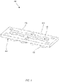
FIG. 5 illustrates a perspective view of a resonator chamber in accordance with the invention; and -
FIG. 6 illustrates a perspective view of a low pressure compressor case in accordance with various embodiments. - Referring to
FIG. 1 , a gas turbine engine 100 (such as a turbofan gas turbine engine) is illustrated according to various embodiments.Gas turbine engine 100 is disposed aboutaxial centerline axis 120, which may also be referred to as axis ofrotation 120.Gas turbine engine 100 may comprise afan 140,compressor sections combustion section 180, andturbine sections compressor sections combustion section 180 and expanded acrossturbine sections Turbine sections high pressure rotors 192 andlow pressure rotors 194, which rotate in response to the expansion.Turbine sections blades 196 and static airfoils orvanes 198. A plurality ofbearings 115 may support spools in thegas turbine engine 100.FIG. 1 provides a general understanding of the sections in a gas turbine engine, and is not intended to limit the disclosure. The present disclosure may extend to all types of turbine engines, including turbofan gas turbine engines and turbojet engines, for all types of applications. - The forward-aft positions of
gas turbine engine 100 lie along axis ofrotation 120. For example,fan 140 may be referred to as forward ofturbine section 190 andturbine section 190 may be referred to as aft offan 140. Typically, during operation ofgas turbine engine 100, air flows from forward to aft, for example, fromfan 140 toturbine section 190. As air flows fromfan 140 to the more aft components ofgas turbine engine 100, axis ofrotation 120 may also generally define the direction of the air stream flow. - Referring to
FIG. 2 , a cross-section of a low pressure compressor ("LPC") 200 is illustrated according to various embodiments.LPC 200 may comprise alternating series of rotatingblades 210 and vanes 220 in a core flowpath. LPC 200 may comprise ableed valve 230. In various embodiments, thebleed valve 230 may be located aft of afourth stage 240 ofLPC 200. A bleed valve may control the quantity of air flowing into the high pressure compressor. In an embodiment,bleed valve 230 may be a 2.5 bleed valve.Bleed valve 230 may be opened in order to release bleed air throughbleed duct 250. Bleed air may be released in order to decrease instability in the core flowpath, such as during start, during transient operation, and during reverse thrust operation. - While bleed
valve 230 is closed, bleed air may be prevented from exiting the core flow path throughbleed duct 250. Air flowing acrossbleed duct 250 may create a resonance inbleed duct 250. The resonance may cause vibrational waves to travel forward which may damageblades 210 in the compressor rotor closest to thebleed duct 250. In various embodiments, the compressor rotor closes to thebleed duct 250 may be thefourth stage 240. The frequency of the vibrational waves may be changed to prevent damage by altering the properties ofbleed duct 250, such as a length or volume ofbleed duct 250. -
Bleed valve 230 may be a portion of a compressor control system. The compressor control system may give compressor stability during starting, transient, and reverse thrust operation.Bleed valve 230 may be commanded open by the Electronic Engine Control ("EEC") to bleed fourth stage air into the fan airstream. The EEC is the primary interface between the power plant and the aircraft which includes communication with various aircraft systems, such as thrust lever resolvers, air data/inertial reference systems, engine interface and vibration monitor units, on-board maintenance systems, electronic instrument systems, and automatic flight systems. - Referring to
FIG. 3 , a section-view of a bleedvalve assembly 300 having a resonator chamber is illustrated according to various embodiments. Bleedvalve assembly 300 comprisesbleed valve 310. Bleedvalve 310 may compriseseals 312 which seal bleedduct 320. Anactuator 330 drives bleedvalve 310 forward (toward the actuator 330) in order to release bleed air throughbleed duct 320 and into the fan airstream. Bleedvalve 310 may comprise anaperture 316 inaxial span 314.Aperture 316 may be configured to receive amanifold 400. - Referring to
FIGs. 3 and4 , bleedvalve assembly 300 comprises amanifold 400.Manifold 400 may be located at least partially withinaperture 316 inaxial span 314.Manifold 400 may comprise aplatform 410 and one ormore cylinders 420.Platform 410 may define arecess 412 surroundingcylinders 420.Cylinders 420 may extend radially inward fromplatform 410.Cylinders 420 may comprisepassages 422.Passages 422 allow bleed air to flow betweenbleed duct 320 andresonator chamber 500 ofFIG. 4 . In various embodiments,cylinders 420 may be located withinaperture 316 inaxial span 314. Aninner face 414 ofplatform 410 may be adjacent to anouter face 311 ofaxial span 314. - Referring to
FIGs. 3 and5 , bleedvalve assembly 300 may comprise aresonator chamber 500.Resonator chamber 500 may comprise achamber body assembly 510 and aresonator cover 520.Chamber body assembly 510 may comprise achamber body 512 and achamber flange 514.Chamber body 512 comprises aforward chamber 515 and anaft chamber 518.Forward chamber 515 may be located forward ofaft chamber 518. A depth D1 offorward chamber 515 is less than a depth D2 ofaft chamber 518. Alower surface 517 offorward chamber 515 may be adjacent to anupper flange 318 ofbleed valve 310. Aforward wall 519 ofaft chamber 518 may be adjacent to aforward wall 319 ofbleed valve 310. Thus,chamber body 512 may comprise a stepped profile corresponding to the shape ofbleed valve 310. -
Chamber flange 514 may be located adjacent to a top edge ofchamber body 512. Aninner circumference 561 of chamber flange may be substantially flush with aninner surface 562 ofchamber body 512.Chamber flange 514 may comprisefemale fasteners 516. In various embodiments,female threads 516 may be located inside ofchamber body 512.Female threads 516 may be configured to receive a fastener, such as a bolt or screw.Chamber flange 514 may further comprise acantilevered lip 513 located forward ofchamber body 512.Cantilevered lip 513 may comprisebolt holes 505 configured to receive fasteners.Chamber flange 514 may comprise alignment pegs 511. -
Resonator cover 520 may comprisecover body 522 and coverflange 524.Cover flange 524 may comprisefastener holes 525 and alignment holes 526.Cover flange 524 may be configured to mate withchamber flange 514. Alignment pegs 511 may fit within alignment holes 526 in order to alignresonator cover 520 withchamber flange 514. -
Resonator chamber 500 may be in fluid communication withbleed duct 320. Thus,resonator chamber 500 may alter the resonation properties ofbleed duct 320, and may change the frequency of vibrational waves caused by airflow overbleed duct 320 withbleed valve 310 closed. In various embodiments,resonator cover 520 may be interchangeable with resonator covers having different volumes, which may alter the resonation properties ofbleed duct 320 without changing thechamber body assembly 510. - Referring to
FIG. 6 , a perspective view of a low pressure compressor ("LPC")case 600 is illustrated according to various embodiments.LPC case 600 may comprise one or more highprofile resonator chambers 610 corresponding to bleed ducts. In various embodiments, the plurality of highprofile resonator chambers 610 may each have the same volume. In various embodiments,LPC case 600 may comprise one or more lowprofile resonator chambers 620. In various embodiments, a height of the highprofile resonator chambers 610 may be greater than a height of the lowprofile resonator chamber 620. However, a length L1 of the highprofile resonator chambers 610 may be less than a length L2 of the lowprofile resonator chamber 620. Thus, a volume of the highprofile resonator chambers 610 may be equal to a volume of the lowprofile resonator chamber 620. Different shapes of resonator chambers may be used in order to meet space restraint requirements while maintaining equal volumes. In various embodiments, all resonator chambers may have the same volume. However, in various embodiments different resonator chambers may have different volumes.
Claims (6)
- A low pressure compressor ("LPC") case (600) comprising:a first bleed duct (250; 320); anda first bleed valve assembly (300) configured to seal the first bleed duct (250; 320), the first bleed valve assembly (300) comprising:a first resonator chamber (500, 610) which is in fluid communication with the first bleed duct;a bleed valve (230; 310); andan actuator (330) configured to drive the bleed valve (230; 310) toward the actuator (330) in order to release bleed air through the bleed duct (320);characterised in that:
the first resonator chamber (500, 610) comprises a forward chamber portion (515) and an aft chamber portion (518), wherein a depth (D1) of the forward chamber portion (515) is less than a depth (D2) of the aft chamber portion (518), such that the resonator chamber has a stepped profile corresponding to a shape of the bleed valve to which it is adjacent. - The LPC case of claim 1, further comprising a second bleed duct and a second bleed valve assembly configured to seal the second bleed duct, the second bleed valve assembly comprising a second resonator chamber (620).
- The LPC case of claim 2, wherein a height of the first resonator chamber (500, 610) is greater than a height of the second resonator chamber (620).
- The LPC case of claim 2 or 3, wherein a volume of the first resonator chamber (500, 610) is equal to a volume of the second resonator chamber (620).
- The LPC case of any preceding claim, wherein the first bleed valve assembly (300) comprises a manifold (400), a chamber body assembly (510), and a resonator cover (520).
- The LPC case of any preceding claim, wherein the first bleed valve assembly (300) comprises a 2.5 bleed valve.
Applications Claiming Priority (2)
| Application Number | Priority Date | Filing Date | Title |
|---|---|---|---|
| US201462027372P | 2014-07-22 | 2014-07-22 | |
| EP15177633.3A EP2977617B1 (en) | 2014-07-22 | 2015-07-21 | Bleed valve with resonance chamber integrated in the closing member |
Related Parent Applications (2)
| Application Number | Title | Priority Date | Filing Date |
|---|---|---|---|
| EP15177633.3A Division EP2977617B1 (en) | 2014-07-22 | 2015-07-21 | Bleed valve with resonance chamber integrated in the closing member |
| EP15177633.3A Division-Into EP2977617B1 (en) | 2014-07-22 | 2015-07-21 | Bleed valve with resonance chamber integrated in the closing member |
Publications (2)
| Publication Number | Publication Date |
|---|---|
| EP3597927A1 EP3597927A1 (en) | 2020-01-22 |
| EP3597927B1 true EP3597927B1 (en) | 2022-06-22 |
Family
ID=53761201
Family Applications (2)
| Application Number | Title | Priority Date | Filing Date |
|---|---|---|---|
| EP19195221.7A Active EP3597927B1 (en) | 2014-07-22 | 2015-07-21 | Bleed valve with resonance chamber integrated in the closing member |
| EP15177633.3A Active EP2977617B1 (en) | 2014-07-22 | 2015-07-21 | Bleed valve with resonance chamber integrated in the closing member |
Family Applications After (1)
| Application Number | Title | Priority Date | Filing Date |
|---|---|---|---|
| EP15177633.3A Active EP2977617B1 (en) | 2014-07-22 | 2015-07-21 | Bleed valve with resonance chamber integrated in the closing member |
Country Status (2)
| Country | Link |
|---|---|
| US (1) | US9879611B2 (en) |
| EP (2) | EP3597927B1 (en) |
Families Citing this family (11)
| Publication number | Priority date | Publication date | Assignee | Title |
|---|---|---|---|---|
| US10260643B2 (en) * | 2014-12-02 | 2019-04-16 | United Technologies Corporation | Bleed valve resonator drain |
| US10794272B2 (en) * | 2018-02-19 | 2020-10-06 | General Electric Company | Axial and centrifugal compressor |
| US11530650B2 (en) * | 2018-07-13 | 2022-12-20 | Raytheon Technologies Corporation | Gas turbine engine with active variable turbine cooling |
| GB2580128B (en) * | 2018-12-21 | 2021-12-01 | Gkn Aerospace Sweden Ab | Plenum resonance prevention arrangement |
| US11859536B2 (en) * | 2019-05-31 | 2024-01-02 | Pratt & Whitney Canada Corp. | Air system of multi-engine aircraft |
| US11346240B2 (en) * | 2019-06-07 | 2022-05-31 | Raytheon Technologies Corporation | Gas turbine engine bleed valve damping guide link |
| US12366202B2 (en) | 2022-01-18 | 2025-07-22 | General Electric Company | Bleed valve assemblies |
| US11739698B2 (en) | 2022-01-19 | 2023-08-29 | General Electric Company | Aero-acoustically dampened bleed valve |
| US12320259B2 (en) | 2022-06-27 | 2025-06-03 | General Electric Company | Compact bleed valve assemblies |
| US20250179964A1 (en) * | 2023-08-14 | 2025-06-05 | General Electric Company | Variable bleed valve assemblies |
| US12546261B1 (en) * | 2025-03-25 | 2026-02-10 | Rolls-Royce North American Technologies Inc. | Compressor bleed air collector and exhaust ducting for gas turbine engine systems |
Family Cites Families (9)
| Publication number | Priority date | Publication date | Assignee | Title |
|---|---|---|---|---|
| US5287697A (en) * | 1992-01-02 | 1994-02-22 | General Electric Company | Variable area bypass injector seal |
| US6106227A (en) | 1998-02-27 | 2000-08-22 | United Technologies Corporation | Roller assembly for guiding an actuating ring |
| US7555905B2 (en) * | 2006-03-28 | 2009-07-07 | United Technologies Corporation | Self-actuating bleed valve for gas turbine engine |
| GB2443418B (en) * | 2006-11-02 | 2011-05-04 | Rolls Royce Plc | An acoustic arrangement |
| US7966831B2 (en) | 2007-08-28 | 2011-06-28 | General Electric Company | Apparatus and method for suppressing dynamic pressure instability in bleed duct |
| CA2642141A1 (en) * | 2008-10-20 | 2010-04-20 | Innovative Microelectronics Inc. | Flange alignment pin |
| US8973365B2 (en) | 2010-10-29 | 2015-03-10 | Solar Turbines Incorporated | Gas turbine combustor with mounting for Helmholtz resonators |
| US9353876B2 (en) * | 2012-03-19 | 2016-05-31 | William E. Woollenweber | Boost pressure control system for turbocharged internal combustion engines |
| US8893690B2 (en) * | 2012-05-10 | 2014-11-25 | Caterpillar Inc. | Check valve for an engine breather assembly |
-
2015
- 2015-06-29 US US14/754,298 patent/US9879611B2/en active Active
- 2015-07-21 EP EP19195221.7A patent/EP3597927B1/en active Active
- 2015-07-21 EP EP15177633.3A patent/EP2977617B1/en active Active
Also Published As
| Publication number | Publication date |
|---|---|
| US9879611B2 (en) | 2018-01-30 |
| US20160153361A1 (en) | 2016-06-02 |
| EP2977617A1 (en) | 2016-01-27 |
| EP3597927A1 (en) | 2020-01-22 |
| EP2977617B1 (en) | 2019-10-23 |
Similar Documents
| Publication | Publication Date | Title |
|---|---|---|
| EP3597927B1 (en) | Bleed valve with resonance chamber integrated in the closing member | |
| US10583933B2 (en) | Method and apparatus for undercowl flow diversion cooling | |
| EP3181829B1 (en) | Gas turbine engine turbine cooling system | |
| US9328618B2 (en) | High-pressure turbine nozzle for a turbojet | |
| US20160177765A1 (en) | Pinned seal | |
| US10247106B2 (en) | Method and system for rotating air seal with integral flexible heat shield | |
| EP3231997A1 (en) | Gas turbine engine airfoil bleed | |
| US8075246B2 (en) | Relief device for a turbojet and a turbojet comprising same | |
| US11492912B2 (en) | Trailing edge pressure and flow regulator | |
| EP2977564A1 (en) | Bleed valve assembly with resonator chamber | |
| US12085027B2 (en) | Compressor bleed for gas turbine engine | |
| US10036263B2 (en) | Stator assembly with pad interface for a gas turbine engine | |
| EP3323995B1 (en) | Airfoil with laterally insertable baffle | |
| CN110939517B (en) | Cladding active clearance control structure | |
| US10125619B2 (en) | Rotor assembly for use in a turbofan engine and method of assembling | |
| JP5072207B2 (en) | Turbine module for a gas turbine engine having a rotor including a monoblock body | |
| EP3203027A1 (en) | Turbine engine airfoil with cooling | |
| EP3748133B1 (en) | Fatigue resistant blade outer air seal | |
| US20160201566A1 (en) | Large displacement high temperature seal | |
| US20260055774A1 (en) | Gas turbine engine bleed air flow control | |
| US20140064969A1 (en) | Blade outer air seal |
Legal Events
| Date | Code | Title | Description |
|---|---|---|---|
| PUAI | Public reference made under article 153(3) epc to a published international application that has entered the european phase |
Free format text: ORIGINAL CODE: 0009012 |
|
| STAA | Information on the status of an ep patent application or granted ep patent |
Free format text: STATUS: THE APPLICATION HAS BEEN PUBLISHED |
|
| AC | Divisional application: reference to earlier application |
Ref document number: 2977617 Country of ref document: EP Kind code of ref document: P |
|
| AK | Designated contracting states |
Kind code of ref document: A1 Designated state(s): AL AT BE BG CH CY CZ DE DK EE ES FI FR GB GR HR HU IE IS IT LI LT LU LV MC MK MT NL NO PL PT RO RS SE SI SK SM TR |
|
| STAA | Information on the status of an ep patent application or granted ep patent |
Free format text: STATUS: REQUEST FOR EXAMINATION WAS MADE |
|
| 17P | Request for examination filed |
Effective date: 20200722 |
|
| RBV | Designated contracting states (corrected) |
Designated state(s): AL AT BE BG CH CY CZ DE DK EE ES FI FR GB GR HR HU IE IS IT LI LT LU LV MC MK MT NL NO PL PT RO RS SE SI SK SM TR |
|
| RAP1 | Party data changed (applicant data changed or rights of an application transferred) |
Owner name: RAYTHEON TECHNOLOGIES CORPORATION |
|
| GRAP | Despatch of communication of intention to grant a patent |
Free format text: ORIGINAL CODE: EPIDOSNIGR1 |
|
| STAA | Information on the status of an ep patent application or granted ep patent |
Free format text: STATUS: GRANT OF PATENT IS INTENDED |
|
| INTG | Intention to grant announced |
Effective date: 20220110 |
|
| GRAS | Grant fee paid |
Free format text: ORIGINAL CODE: EPIDOSNIGR3 |
|
| GRAA | (expected) grant |
Free format text: ORIGINAL CODE: 0009210 |
|
| STAA | Information on the status of an ep patent application or granted ep patent |
Free format text: STATUS: THE PATENT HAS BEEN GRANTED |
|
| AC | Divisional application: reference to earlier application |
Ref document number: 2977617 Country of ref document: EP Kind code of ref document: P |
|
| AK | Designated contracting states |
Kind code of ref document: B1 Designated state(s): AL AT BE BG CH CY CZ DE DK EE ES FI FR GB GR HR HU IE IS IT LI LT LU LV MC MK MT NL NO PL PT RO RS SE SI SK SM TR |
|
| REG | Reference to a national code |
Ref country code: GB Ref legal event code: FG4D |
|
| REG | Reference to a national code |
Ref country code: CH Ref legal event code: EP |
|
| REG | Reference to a national code |
Ref country code: DE Ref legal event code: R096 Ref document number: 602015079613 Country of ref document: DE |
|
| REG | Reference to a national code |
Ref country code: AT Ref legal event code: REF Ref document number: 1499940 Country of ref document: AT Kind code of ref document: T Effective date: 20220715 |
|
| REG | Reference to a national code |
Ref country code: IE Ref legal event code: FG4D |
|
| REG | Reference to a national code |
Ref country code: LT Ref legal event code: MG9D |
|
| REG | Reference to a national code |
Ref country code: NL Ref legal event code: MP Effective date: 20220622 |
|
| PG25 | Lapsed in a contracting state [announced via postgrant information from national office to epo] |
Ref country code: SE Free format text: LAPSE BECAUSE OF FAILURE TO SUBMIT A TRANSLATION OF THE DESCRIPTION OR TO PAY THE FEE WITHIN THE PRESCRIBED TIME-LIMIT Effective date: 20220622 Ref country code: NO Free format text: LAPSE BECAUSE OF FAILURE TO SUBMIT A TRANSLATION OF THE DESCRIPTION OR TO PAY THE FEE WITHIN THE PRESCRIBED TIME-LIMIT Effective date: 20220922 Ref country code: LT Free format text: LAPSE BECAUSE OF FAILURE TO SUBMIT A TRANSLATION OF THE DESCRIPTION OR TO PAY THE FEE WITHIN THE PRESCRIBED TIME-LIMIT Effective date: 20220622 Ref country code: HR Free format text: LAPSE BECAUSE OF FAILURE TO SUBMIT A TRANSLATION OF THE DESCRIPTION OR TO PAY THE FEE WITHIN THE PRESCRIBED TIME-LIMIT Effective date: 20220622 Ref country code: GR Free format text: LAPSE BECAUSE OF FAILURE TO SUBMIT A TRANSLATION OF THE DESCRIPTION OR TO PAY THE FEE WITHIN THE PRESCRIBED TIME-LIMIT Effective date: 20220923 Ref country code: FI Free format text: LAPSE BECAUSE OF FAILURE TO SUBMIT A TRANSLATION OF THE DESCRIPTION OR TO PAY THE FEE WITHIN THE PRESCRIBED TIME-LIMIT Effective date: 20220622 Ref country code: BG Free format text: LAPSE BECAUSE OF FAILURE TO SUBMIT A TRANSLATION OF THE DESCRIPTION OR TO PAY THE FEE WITHIN THE PRESCRIBED TIME-LIMIT Effective date: 20220922 |
|
| REG | Reference to a national code |
Ref country code: AT Ref legal event code: MK05 Ref document number: 1499940 Country of ref document: AT Kind code of ref document: T Effective date: 20220622 |
|
| PG25 | Lapsed in a contracting state [announced via postgrant information from national office to epo] |
Ref country code: RS Free format text: LAPSE BECAUSE OF FAILURE TO SUBMIT A TRANSLATION OF THE DESCRIPTION OR TO PAY THE FEE WITHIN THE PRESCRIBED TIME-LIMIT Effective date: 20220622 Ref country code: LV Free format text: LAPSE BECAUSE OF FAILURE TO SUBMIT A TRANSLATION OF THE DESCRIPTION OR TO PAY THE FEE WITHIN THE PRESCRIBED TIME-LIMIT Effective date: 20220622 |
|
| PG25 | Lapsed in a contracting state [announced via postgrant information from national office to epo] |
Ref country code: NL Free format text: LAPSE BECAUSE OF FAILURE TO SUBMIT A TRANSLATION OF THE DESCRIPTION OR TO PAY THE FEE WITHIN THE PRESCRIBED TIME-LIMIT Effective date: 20220622 |
|
| PG25 | Lapsed in a contracting state [announced via postgrant information from national office to epo] |
Ref country code: SM Free format text: LAPSE BECAUSE OF FAILURE TO SUBMIT A TRANSLATION OF THE DESCRIPTION OR TO PAY THE FEE WITHIN THE PRESCRIBED TIME-LIMIT Effective date: 20220622 Ref country code: SK Free format text: LAPSE BECAUSE OF FAILURE TO SUBMIT A TRANSLATION OF THE DESCRIPTION OR TO PAY THE FEE WITHIN THE PRESCRIBED TIME-LIMIT Effective date: 20220622 Ref country code: RO Free format text: LAPSE BECAUSE OF FAILURE TO SUBMIT A TRANSLATION OF THE DESCRIPTION OR TO PAY THE FEE WITHIN THE PRESCRIBED TIME-LIMIT Effective date: 20220622 Ref country code: PT Free format text: LAPSE BECAUSE OF FAILURE TO SUBMIT A TRANSLATION OF THE DESCRIPTION OR TO PAY THE FEE WITHIN THE PRESCRIBED TIME-LIMIT Effective date: 20221024 Ref country code: ES Free format text: LAPSE BECAUSE OF FAILURE TO SUBMIT A TRANSLATION OF THE DESCRIPTION OR TO PAY THE FEE WITHIN THE PRESCRIBED TIME-LIMIT Effective date: 20220622 Ref country code: EE Free format text: LAPSE BECAUSE OF FAILURE TO SUBMIT A TRANSLATION OF THE DESCRIPTION OR TO PAY THE FEE WITHIN THE PRESCRIBED TIME-LIMIT Effective date: 20220622 Ref country code: CZ Free format text: LAPSE BECAUSE OF FAILURE TO SUBMIT A TRANSLATION OF THE DESCRIPTION OR TO PAY THE FEE WITHIN THE PRESCRIBED TIME-LIMIT Effective date: 20220622 Ref country code: AT Free format text: LAPSE BECAUSE OF FAILURE TO SUBMIT A TRANSLATION OF THE DESCRIPTION OR TO PAY THE FEE WITHIN THE PRESCRIBED TIME-LIMIT Effective date: 20220622 |
|
| PG25 | Lapsed in a contracting state [announced via postgrant information from national office to epo] |
Ref country code: PL Free format text: LAPSE BECAUSE OF FAILURE TO SUBMIT A TRANSLATION OF THE DESCRIPTION OR TO PAY THE FEE WITHIN THE PRESCRIBED TIME-LIMIT Effective date: 20220622 Ref country code: IS Free format text: LAPSE BECAUSE OF FAILURE TO SUBMIT A TRANSLATION OF THE DESCRIPTION OR TO PAY THE FEE WITHIN THE PRESCRIBED TIME-LIMIT Effective date: 20221022 |
|
| REG | Reference to a national code |
Ref country code: CH Ref legal event code: PL |
|
| REG | Reference to a national code |
Ref country code: DE Ref legal event code: R097 Ref document number: 602015079613 Country of ref document: DE |
|
| REG | Reference to a national code |
Ref country code: BE Ref legal event code: MM Effective date: 20220731 |
|
| PG25 | Lapsed in a contracting state [announced via postgrant information from national office to epo] |
Ref country code: MC Free format text: LAPSE BECAUSE OF FAILURE TO SUBMIT A TRANSLATION OF THE DESCRIPTION OR TO PAY THE FEE WITHIN THE PRESCRIBED TIME-LIMIT Effective date: 20220622 Ref country code: AL Free format text: LAPSE BECAUSE OF FAILURE TO SUBMIT A TRANSLATION OF THE DESCRIPTION OR TO PAY THE FEE WITHIN THE PRESCRIBED TIME-LIMIT Effective date: 20220622 |
|
| PG25 | Lapsed in a contracting state [announced via postgrant information from national office to epo] |
Ref country code: LU Free format text: LAPSE BECAUSE OF NON-PAYMENT OF DUE FEES Effective date: 20220721 Ref country code: LI Free format text: LAPSE BECAUSE OF NON-PAYMENT OF DUE FEES Effective date: 20220731 Ref country code: DK Free format text: LAPSE BECAUSE OF FAILURE TO SUBMIT A TRANSLATION OF THE DESCRIPTION OR TO PAY THE FEE WITHIN THE PRESCRIBED TIME-LIMIT Effective date: 20220622 Ref country code: CH Free format text: LAPSE BECAUSE OF NON-PAYMENT OF DUE FEES Effective date: 20220731 |
|
| PLBE | No opposition filed within time limit |
Free format text: ORIGINAL CODE: 0009261 |
|
| STAA | Information on the status of an ep patent application or granted ep patent |
Free format text: STATUS: NO OPPOSITION FILED WITHIN TIME LIMIT |
|
| 26N | No opposition filed |
Effective date: 20230323 |
|
| PG25 | Lapsed in a contracting state [announced via postgrant information from national office to epo] |
Ref country code: BE Free format text: LAPSE BECAUSE OF NON-PAYMENT OF DUE FEES Effective date: 20220731 |
|
| P01 | Opt-out of the competence of the unified patent court (upc) registered |
Effective date: 20230521 |
|
| PG25 | Lapsed in a contracting state [announced via postgrant information from national office to epo] |
Ref country code: IE Free format text: LAPSE BECAUSE OF NON-PAYMENT OF DUE FEES Effective date: 20220721 |
|
| PG25 | Lapsed in a contracting state [announced via postgrant information from national office to epo] |
Ref country code: SI Free format text: LAPSE BECAUSE OF FAILURE TO SUBMIT A TRANSLATION OF THE DESCRIPTION OR TO PAY THE FEE WITHIN THE PRESCRIBED TIME-LIMIT Effective date: 20220622 |
|
| PG25 | Lapsed in a contracting state [announced via postgrant information from national office to epo] |
Ref country code: IT Free format text: LAPSE BECAUSE OF FAILURE TO SUBMIT A TRANSLATION OF THE DESCRIPTION OR TO PAY THE FEE WITHIN THE PRESCRIBED TIME-LIMIT Effective date: 20220622 |
|
| PG25 | Lapsed in a contracting state [announced via postgrant information from national office to epo] |
Ref country code: HU Free format text: LAPSE BECAUSE OF FAILURE TO SUBMIT A TRANSLATION OF THE DESCRIPTION OR TO PAY THE FEE WITHIN THE PRESCRIBED TIME-LIMIT; INVALID AB INITIO Effective date: 20150721 |
|
| PG25 | Lapsed in a contracting state [announced via postgrant information from national office to epo] |
Ref country code: MK Free format text: LAPSE BECAUSE OF FAILURE TO SUBMIT A TRANSLATION OF THE DESCRIPTION OR TO PAY THE FEE WITHIN THE PRESCRIBED TIME-LIMIT Effective date: 20220622 Ref country code: CY Free format text: LAPSE BECAUSE OF FAILURE TO SUBMIT A TRANSLATION OF THE DESCRIPTION OR TO PAY THE FEE WITHIN THE PRESCRIBED TIME-LIMIT Effective date: 20220622 |
|
| PG25 | Lapsed in a contracting state [announced via postgrant information from national office to epo] |
Ref country code: TR Free format text: LAPSE BECAUSE OF FAILURE TO SUBMIT A TRANSLATION OF THE DESCRIPTION OR TO PAY THE FEE WITHIN THE PRESCRIBED TIME-LIMIT Effective date: 20220622 |
|
| PG25 | Lapsed in a contracting state [announced via postgrant information from national office to epo] |
Ref country code: MT Free format text: LAPSE BECAUSE OF FAILURE TO SUBMIT A TRANSLATION OF THE DESCRIPTION OR TO PAY THE FEE WITHIN THE PRESCRIBED TIME-LIMIT Effective date: 20220622 |
|
| PG25 | Lapsed in a contracting state [announced via postgrant information from national office to epo] |
Ref country code: BG Free format text: LAPSE BECAUSE OF FAILURE TO SUBMIT A TRANSLATION OF THE DESCRIPTION OR TO PAY THE FEE WITHIN THE PRESCRIBED TIME-LIMIT Effective date: 20220622 |
|
| PG25 | Lapsed in a contracting state [announced via postgrant information from national office to epo] |
Ref country code: BG Free format text: LAPSE BECAUSE OF FAILURE TO SUBMIT A TRANSLATION OF THE DESCRIPTION OR TO PAY THE FEE WITHIN THE PRESCRIBED TIME-LIMIT Effective date: 20220622 |
|
| PGFP | Annual fee paid to national office [announced via postgrant information from national office to epo] |
Ref country code: GB Payment date: 20250619 Year of fee payment: 11 |
|
| PGFP | Annual fee paid to national office [announced via postgrant information from national office to epo] |
Ref country code: FR Payment date: 20250620 Year of fee payment: 11 |
|
| REG | Reference to a national code |
Ref country code: DE Ref legal event code: R081 Ref document number: 602015079613 Country of ref document: DE Owner name: RTX CORPORATION (N.D.GES.D. STAATES DELAWARE),, US Free format text: FORMER OWNER: RAYTHEON TECHNOLOGIES CORPORATION, FARMINGTON, CT, US |
|
| PGFP | Annual fee paid to national office [announced via postgrant information from national office to epo] |
Ref country code: DE Payment date: 20250620 Year of fee payment: 11 |