EP3597896B1 - Boundary layer ingesting fan - Google Patents
Boundary layer ingesting fan Download PDFInfo
- Publication number
- EP3597896B1 EP3597896B1 EP19187129.2A EP19187129A EP3597896B1 EP 3597896 B1 EP3597896 B1 EP 3597896B1 EP 19187129 A EP19187129 A EP 19187129A EP 3597896 B1 EP3597896 B1 EP 3597896B1
- Authority
- EP
- European Patent Office
- Prior art keywords
- fan
- pitch
- fan blades
- angle
- blades
- Prior art date
- Legal status (The legal status is an assumption and is not a legal conclusion. Google has not performed a legal analysis and makes no representation as to the accuracy of the status listed.)
- Active
Links
Images



Classifications
-
- F—MECHANICAL ENGINEERING; LIGHTING; HEATING; WEAPONS; BLASTING
- F02—COMBUSTION ENGINES; HOT-GAS OR COMBUSTION-PRODUCT ENGINE PLANTS
- F02K—JET-PROPULSION PLANTS
- F02K3/00—Plants including a gas turbine driving a compressor or a ducted fan
- F02K3/02—Plants including a gas turbine driving a compressor or a ducted fan in which part of the working fluid by-passes the turbine and combustion chamber
- F02K3/04—Plants including a gas turbine driving a compressor or a ducted fan in which part of the working fluid by-passes the turbine and combustion chamber the plant including ducted fans, i.e. fans with high volume, low pressure outputs, for augmenting the jet thrust, e.g. of double-flow type
- F02K3/06—Plants including a gas turbine driving a compressor or a ducted fan in which part of the working fluid by-passes the turbine and combustion chamber the plant including ducted fans, i.e. fans with high volume, low pressure outputs, for augmenting the jet thrust, e.g. of double-flow type with front fan
-
- B—PERFORMING OPERATIONS; TRANSPORTING
- B64—AIRCRAFT; AVIATION; COSMONAUTICS
- B64C—AEROPLANES; HELICOPTERS
- B64C11/00—Propellers, e.g. of ducted type; Features common to propellers and rotors for rotorcraft
- B64C11/02—Hub construction
- B64C11/04—Blade mountings
- B64C11/06—Blade mountings for variable-pitch blades
-
- B—PERFORMING OPERATIONS; TRANSPORTING
- B64—AIRCRAFT; AVIATION; COSMONAUTICS
- B64C—AEROPLANES; HELICOPTERS
- B64C21/00—Influencing air flow over aircraft surfaces by affecting boundary layer flow
- B64C21/01—Boundary layer ingestion [BLI] propulsion
-
- B—PERFORMING OPERATIONS; TRANSPORTING
- B64—AIRCRAFT; AVIATION; COSMONAUTICS
- B64D—EQUIPMENT FOR FITTING IN OR TO AIRCRAFT; FLIGHT SUITS; PARACHUTES; ARRANGEMENT OR MOUNTING OF POWER PLANTS OR PROPULSION TRANSMISSIONS IN AIRCRAFT
- B64D27/00—Arrangement or mounting of power plants in aircraft; Aircraft characterised by the type or position of power plants
- B64D27/02—Aircraft characterised by the type or position of power plants
- B64D27/16—Aircraft characterised by the type or position of power plants of jet type
- B64D27/20—Aircraft characterised by the type or position of power plants of jet type within, or attached to, fuselages
-
- F—MECHANICAL ENGINEERING; LIGHTING; HEATING; WEAPONS; BLASTING
- F01—MACHINES OR ENGINES IN GENERAL; ENGINE PLANTS IN GENERAL; STEAM ENGINES
- F01D—NON-POSITIVE DISPLACEMENT MACHINES OR ENGINES, e.g. STEAM TURBINES
- F01D1/00—Non-positive-displacement machines or engines, e.g. steam turbines
- F01D1/30—Non-positive-displacement machines or engines, e.g. steam turbines characterised by having a single rotor operable in either direction of rotation, e.g. by reversing of blades
-
- F—MECHANICAL ENGINEERING; LIGHTING; HEATING; WEAPONS; BLASTING
- F01—MACHINES OR ENGINES IN GENERAL; ENGINE PLANTS IN GENERAL; STEAM ENGINES
- F01D—NON-POSITIVE DISPLACEMENT MACHINES OR ENGINES, e.g. STEAM TURBINES
- F01D7/00—Rotors with blades adjustable in operation; Control thereof
- F01D7/02—Rotors with blades adjustable in operation; Control thereof having adjustment responsive to speed
-
- B—PERFORMING OPERATIONS; TRANSPORTING
- B64—AIRCRAFT; AVIATION; COSMONAUTICS
- B64C—AEROPLANES; HELICOPTERS
- B64C11/00—Propellers, e.g. of ducted type; Features common to propellers and rotors for rotorcraft
- B64C11/001—Shrouded propellers
-
- B—PERFORMING OPERATIONS; TRANSPORTING
- B64—AIRCRAFT; AVIATION; COSMONAUTICS
- B64D—EQUIPMENT FOR FITTING IN OR TO AIRCRAFT; FLIGHT SUITS; PARACHUTES; ARRANGEMENT OR MOUNTING OF POWER PLANTS OR PROPULSION TRANSMISSIONS IN AIRCRAFT
- B64D27/00—Arrangement or mounting of power plants in aircraft; Aircraft characterised by the type or position of power plants
- B64D27/02—Aircraft characterised by the type or position of power plants
- B64D27/10—Aircraft characterised by the type or position of power plants of gas-turbine type
- B64D27/14—Aircraft characterised by the type or position of power plants of gas-turbine type within, or attached to, fuselages
-
- F—MECHANICAL ENGINEERING; LIGHTING; HEATING; WEAPONS; BLASTING
- F05—INDEXING SCHEMES RELATING TO ENGINES OR PUMPS IN VARIOUS SUBCLASSES OF CLASSES F01-F04
- F05D—INDEXING SCHEME FOR ASPECTS RELATING TO NON-POSITIVE-DISPLACEMENT MACHINES OR ENGINES, GAS-TURBINES OR JET-PROPULSION PLANTS
- F05D2220/00—Application
- F05D2220/30—Application in turbines
- F05D2220/36—Application in turbines specially adapted for the fan of turbofan engines
-
- F—MECHANICAL ENGINEERING; LIGHTING; HEATING; WEAPONS; BLASTING
- F05—INDEXING SCHEMES RELATING TO ENGINES OR PUMPS IN VARIOUS SUBCLASSES OF CLASSES F01-F04
- F05D—INDEXING SCHEME FOR ASPECTS RELATING TO NON-POSITIVE-DISPLACEMENT MACHINES OR ENGINES, GAS-TURBINES OR JET-PROPULSION PLANTS
- F05D2260/00—Function
- F05D2260/70—Adjusting of angle of incidence or attack of rotating blades
-
- F—MECHANICAL ENGINEERING; LIGHTING; HEATING; WEAPONS; BLASTING
- F05—INDEXING SCHEMES RELATING TO ENGINES OR PUMPS IN VARIOUS SUBCLASSES OF CLASSES F01-F04
- F05D—INDEXING SCHEME FOR ASPECTS RELATING TO NON-POSITIVE-DISPLACEMENT MACHINES OR ENGINES, GAS-TURBINES OR JET-PROPULSION PLANTS
- F05D2260/00—Function
- F05D2260/70—Adjusting of angle of incidence or attack of rotating blades
- F05D2260/71—Adjusting of angle of incidence or attack of rotating blades as a function of flow velocity
-
- F—MECHANICAL ENGINEERING; LIGHTING; HEATING; WEAPONS; BLASTING
- F05—INDEXING SCHEMES RELATING TO ENGINES OR PUMPS IN VARIOUS SUBCLASSES OF CLASSES F01-F04
- F05D—INDEXING SCHEME FOR ASPECTS RELATING TO NON-POSITIVE-DISPLACEMENT MACHINES OR ENGINES, GAS-TURBINES OR JET-PROPULSION PLANTS
- F05D2260/00—Function
- F05D2260/70—Adjusting of angle of incidence or attack of rotating blades
- F05D2260/74—Adjusting of angle of incidence or attack of rotating blades by turning around an axis perpendicular the rotor centre line
-
- Y—GENERAL TAGGING OF NEW TECHNOLOGICAL DEVELOPMENTS; GENERAL TAGGING OF CROSS-SECTIONAL TECHNOLOGIES SPANNING OVER SEVERAL SECTIONS OF THE IPC; TECHNICAL SUBJECTS COVERED BY FORMER USPC CROSS-REFERENCE ART COLLECTIONS [XRACs] AND DIGESTS
- Y02—TECHNOLOGIES OR APPLICATIONS FOR MITIGATION OR ADAPTATION AGAINST CLIMATE CHANGE
- Y02T—CLIMATE CHANGE MITIGATION TECHNOLOGIES RELATED TO TRANSPORTATION
- Y02T50/00—Aeronautics or air transport
- Y02T50/10—Drag reduction
Definitions
- Conventional aircraft architecture includes wing mounted gas turbine engines. Alternate aircraft architectures mount the gas turbine engines atop the fuselage or on opposite sides of the aircraft fuselage adjacent to a surface. Accordingly, a portion of an engine fan may ingest portions of a boundary layer of airflow while other portions of the fan spaced apart from the aircraft surface may not encounter boundary layer flow. Differences in airflow characteristics across different parts of the fan can impact fan efficiency.
- US 9 200 594 discloses a fan assembly according to the preamble of claim 1, and a gas turbine engine according to the preamble of claim 4.
- US 4 124 330 A discloses a cam-operated pitch-change apparatus and
- US 2017/138370 A1 discloses a pitch range for a variable pitch fan.
- a fan assembly for a gas turbine engine as set forth in claim 1.
- an aircraft 10 includes a fuselage 12 and a propulsion system 18 mounted within an aft end of the fuselage 12.
- the example propulsion system 18 includes first and second gas turbine engines (not shown) that drive corresponding fan assemblies 16.
- a representation of airflow velocities within the circumference of the fan assembly 16 is indicated at 30 and relates airflow to an angular position within the circumference of the fan 16.
- the fan assemblies 16 are mounted adjacent to surfaces of the fuselage 12 and therefore encounter non-uniform airflow velocities that vary within a circumferential region of the fan inlet area.
- the airflow velocities vary in a way corresponding with proximity to or distance from the surface 28 of the fuselage 12. The closer to the surface 28, the slower the airflow. The further away from the surface 28, the higher the airflow velocity.
- the non-uniform airflow velocities create different regions including a lower velocity region schematically shown at 32 and a higher velocity region 34. The differences in inlet airflow velocities result in differing output velocities of airflow.
- the disclosed fan assembly 16 includes a mechanism to adjust the pitch of each fan blade 20 depending on a circumferential position in order to provide the proper blade pitch corresponding to the incoming airflow velocity vector.
- the incoming airflow velocity vector is the resultant vector of the blade rotation and airflow speed.
- the resulting outlet airflow field then becomes more uniform and efficient. The fan will also see less mechanical stress and vibration.
- each blade 20 is moved from a lower pitch angle 48 ( Figure 4 ) to a higher pitch angle 50 ( Figure 5 ) depending on the incoming airflow incidence 58, where an incidence angle 58 is defined as the angle between the chord line of the blade and the direction of incoming airflow.
- Airflow at higher velocities and higher incidence angle 58 such as those shown in region 34 in Figure 3 do not require the fan blades to perform as much work as those within the region 32 of lower airflow velocities in order to obtain a uniform output flow.
- the higher pitch angle 50 performs more work to generate the exhaust flow than that of the lower pitch angle 48.
- the lower pitch angle 48 is provided in regions 34 with higher incoming airflow velocity such that overall airflow exiting the fan assembly 16 to provide the desired thrust is more uniform about the circumferences of the fan assembly 16.
- the change in pitch angle also optimized blade incidence angle 58 which maximizes fan efficiency.
- the disclosed fan assembly 16 includes a plurality of the fan blades 20 that rotate about the fan rotation axis A.
- Each of the plurality of fan blades 20 are also rotatable about an axis 46 transverse to the axis A to adjust a pitch angle.
- the pitch angle is automatically adjusted depending on a circumferential position of the fan blade 20 to accommodate the varying airflow incidence angles of the airflow field that is shown schematically and indicated at 14.
- the varying airflow field is schematically shown with a front of the flow field shown in Figure 6 .
- the swashplate 42 is a mechanical means of automatically changing the pitch angle for each of the plurality of fan blades separately during rotation about the axis A. No further control or adjustment is provided. Instead, the swashplate sets a defined pitch angle for each circumferential position about the axis A.
- variation of the pitch angle 52 at a circumferential position 54 is illustrated in graph 56.
- the pitch angle 52 varies for each of the plurality of fan blades 20 depending on a circumferential position of each specific fan blade 20.
- a fan blade 20 at the top center position indicated as the 0 degree position in graph 56 will have a first pitch angle.
- a fan blade 20 at or near the bottom position indicated as 180 degrees will have a second different and higher pitch angle.
- the circumferential position 54 of each of the fan blades 20 corresponds with the regions of higher and lower airflow velocities.
- the boundary layer region 36 includes airflows of lower velocities and correspond with higher pitch angles 52.
- the other regions away from the boundary layer as shown at 38 correspond with lower pitch angles 52.
- the fan blades 20 each cycle through the different pitch angles for each of the different circumferential positions about the axis A.
- the variations in pitch angles match each fan blade to the incoming airflow velocities to provide a uniform blade incidence angle, and thus a higher fan efficiency and more uniform exhaust flow.
Landscapes
- Engineering & Computer Science (AREA)
- Aviation & Aerospace Engineering (AREA)
- Mechanical Engineering (AREA)
- General Engineering & Computer Science (AREA)
- Chemical & Material Sciences (AREA)
- Combustion & Propulsion (AREA)
- Structures Of Non-Positive Displacement Pumps (AREA)
Description
- Conventional aircraft architecture includes wing mounted gas turbine engines. Alternate aircraft architectures mount the gas turbine engines atop the fuselage or on opposite sides of the aircraft fuselage adjacent to a surface. Accordingly, a portion of an engine fan may ingest portions of a boundary layer of airflow while other portions of the fan spaced apart from the aircraft surface may not encounter boundary layer flow. Differences in airflow characteristics across different parts of the fan can impact fan efficiency.
-
US 9 200 594 claim 1, and a gas turbine engine according to the preamble ofclaim 4.US 4 124 330 A discloses a cam-operated pitch-change apparatus andUS 2017/138370 A1 discloses a pitch range for a variable pitch fan. - According to a first aspect of the present invention, there is provided a fan assembly for a gas turbine engine as set forth in
claim 1. - According to a further aspect of the present invention, there is provided a gas turbine engine as set forth in
claim 4. - According to a further aspect of the present invention, there is provided a method as set forth in claim 8.
- Embodiments of the disclosure are set forth in the dependent claims.
- These and other features disclosed herein can be best understood from the following specification and drawings, the following of which is a brief description.
-
-
Figure 1 is a schematic view of an aircraft. -
Figure 2 is a schematic view of a portion of the aircraft and a propulsion system. -
Figure 3 is a schematic representation of an incoming airflow velocities. -
Figure 4 is a schematic view of fan blade pitch and incidence angle. -
Figure 5 is a schematic view of another fan blade pitch and incidence angle. -
Figure 6 is a schematic cross-section of an example fan assembly. -
Figure 7 is a graph illustrating fan pitch angle relative to a circumferential position. -
Figure 8 is a schematic cross-section of another example fan assembly. - Referring to the
Figure 1 , anaircraft 10 includes afuselage 12 and apropulsion system 18 mounted within an aft end of thefuselage 12. Theexample propulsion system 18 includes first and second gas turbine engines (not shown) that drivecorresponding fan assemblies 16. - Referring to
Figure 2 with continued reference toFigure 1 , the propulsion system ingestsairflow 22B within eachfan assembly 16. Because thepropulsion system 18 is mounted within and at the aft end of thefuselage 12, the fan assemblies 16 ingest boundary layer airflow schematically shown at 24. Eachfan assembly 16 is partially surrounded by anacelle 26. A portion of thefan assembly 16 not surrounded by thenacelle 26 is disposed aft of asurface 28 of thefuselage 12. Due to boundary layer development alongfuselage 12 andsurface 28 airflow along and abovesurface 28 includesvarying airflow velocity 24 that is less thanairflow velocity 22A which is equal to aircraft speed. This varying airflow velocity creates a non-uniform flow-field entering thefan assembly 16 that results in non-optimal incidence angles for at least some of thefan blades 20. Conventional jet engine fans are designed to receive uniform flow, as in 22A. - The pitch angle for each
fan blade 20 is conventionally the same forfan assemblies 16 not subject to non-uniform airflow velocities. As appreciated, in a conventional nacelle mounted engine, the flow field is substantially uniform and therefore a single blade pitch angle for each fan blade can be utilized and optimized. - Referring to
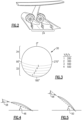
Figures 3 , with continued reference toFigure 2 , a representation of airflow velocities within the circumference of thefan assembly 16 is indicated at 30 and relates airflow to an angular position within the circumference of thefan 16. Thefan assemblies 16 are mounted adjacent to surfaces of thefuselage 12 and therefore encounter non-uniform airflow velocities that vary within a circumferential region of the fan inlet area. The airflow velocities vary in a way corresponding with proximity to or distance from thesurface 28 of thefuselage 12. The closer to thesurface 28, the slower the airflow. The further away from thesurface 28, the higher the airflow velocity. The non-uniform airflow velocities create different regions including a lower velocity region schematically shown at 32 and ahigher velocity region 34. The differences in inlet airflow velocities result in differing output velocities of airflow. - The disclosed
fan assembly 16 includes a mechanism to adjust the pitch of eachfan blade 20 depending on a circumferential position in order to provide the proper blade pitch corresponding to the incoming airflow velocity vector. The incoming airflow velocity vector is the resultant vector of the blade rotation and airflow speed. The resulting outlet airflow field then becomes more uniform and efficient. The fan will also see less mechanical stress and vibration. - Referring to
Figures 4 and 5 with continued reference toFigure 3 , eachblade 20 is moved from a lower pitch angle 48 (Figure 4 ) to a higher pitch angle 50 (Figure 5 ) depending on theincoming airflow incidence 58, where anincidence angle 58 is defined as the angle between the chord line of the blade and the direction of incoming airflow. Airflow at higher velocities andhigher incidence angle 58 such as those shown inregion 34 inFigure 3 do not require the fan blades to perform as much work as those within theregion 32 of lower airflow velocities in order to obtain a uniform output flow. In other words, thehigher pitch angle 50 performs more work to generate the exhaust flow than that of thelower pitch angle 48. However, thelower pitch angle 48 is provided inregions 34 with higher incoming airflow velocity such that overall airflow exiting thefan assembly 16 to provide the desired thrust is more uniform about the circumferences of thefan assembly 16. The change in pitch angle also optimizedblade incidence angle 58 which maximizes fan efficiency. - Referring to
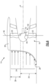
Figure 6 , the disclosedfan assembly 16 includes a plurality of thefan blades 20 that rotate about the fan rotation axis A. Each of the plurality offan blades 20 are also rotatable about anaxis 46 transverse to the axis A to adjust a pitch angle. The pitch angle is automatically adjusted depending on a circumferential position of thefan blade 20 to accommodate the varying airflow incidence angles of the airflow field that is shown schematically and indicated at 14. The varying airflow field is schematically shown with a front of the flow field shown inFigure 6 . - The disclosed
fan assembly 16 includes apitch change mechanism 40 that includes aswashplate 42 that is coupled topivot mechanism 44 for each of the plurality offan blades 20. Theswashplate 42 moves each of thefan blades 20 to adjust a pitch angle as it rotates about the axis A. The pitch angle is increased as eachblade 20 moves into the boundary layer region schematically shown at 36 and decreased as theblade 20 moves back into theregion 38 that is not subject reduced airflow velocities and boundary layer airflow influence. - The
swashplate 42 is a mechanical means of automatically changing the pitch angle for each of the plurality of fan blades separately during rotation about the axis A. No further control or adjustment is provided. Instead, the swashplate sets a defined pitch angle for each circumferential position about the axis A. - Referring to
Figure 7 with continued reference toFigure 6 , variation of the pitch angle 52 at a circumferential position 54 is illustrated in graph 56. The pitch angle 52 varies for each of the plurality offan blades 20 depending on a circumferential position of eachspecific fan blade 20. For example, afan blade 20 at the top center position indicated as the 0 degree position in graph 56 will have a first pitch angle. Afan blade 20 at or near the bottom position indicated as 180 degrees will have a second different and higher pitch angle. The circumferential position 54 of each of thefan blades 20 corresponds with the regions of higher and lower airflow velocities. For example, theboundary layer region 36 includes airflows of lower velocities and correspond with higher pitch angles 52. The other regions away from the boundary layer as shown at 38 correspond with lower pitch angles 52. - Accordingly, the
fan blades 20 each cycle through the different pitch angles for each of the different circumferential positions about the axis A. The variations in pitch angles match each fan blade to the incoming airflow velocities to provide a uniform blade incidence angle, and thus a higher fan efficiency and more uniform exhaust flow. - Referring to
Figure 8 , another fan assembly 60 is shown and includesmotors 62 that are controllable by acontroller 70 to drive apitch mechanism 66 coupled to each of thefan blades 20 for rotating the blades about theaxis 46 to adjust a pitch angle. In this embodiment themotors 62 are electric motors, but other motors as are known could be utilized and are within the contemplation of this disclosure. The pitch angle is adjusted depending on the incoming airflow velocities corresponding to a circumferential position. The blade pitch is adjusted accordingly based on the circumferential position to provide a more uniform exhaust airflow. - It should be understood, that although pitch mechanism have been disclosed and described by way of example, that other control systems and mechanisms for adjusting the pitch angle of each fan blade based on a circumferential positon could be utilized.
- Accordingly, the fan assembly includes features for adjusting a fan blade pitch angle to correspond with a non-uniform incoming airflow velocity field to increase fan efficiency and provide a more uniform exhaust flow.
- Although an embodiment has been disclosed, a worker of ordinary skill in this art would recognize that certain modifications would come within the scope of this disclosure. For that reason, the following claims should be studied to determine the scope and content of this disclosure.
Claims (10)
- A fan assembly (16) for gas turbine engine (18) comprising;a plurality of fan blades (20) rotatable about a fan rotation axis (A), each of the plurality of fan blades (20) movable about an axis (46) transverse to the fan rotation axis (A) to vary the angle of pitch (48, 50) of the fan blades (20);a fan nacelle (26) partially surrounding the plurality of fan blades (20); anda pitch mechanism (40, 66) coupled to the plurality of fan blades (20) that changes the angle of pitch (48, 50) for each of the plurality of fan blades (20) corresponding to a circumferential position of the fan blade about the fan rotation axis (A), characterised in that the fan assembly (16) further comprises:
a flow surface (28) forward of the fan nacelle (26) for only a portion of the circumference of the fan assembly (16), wherein the angle of pitch (48, 50) of one of the plurality of fan blades (20) at a circumferential position within the portion of the circumference of the fan assembly (16) including the flow surface (28) forward of the fan nacelle (26) is greater than the angle of pitch (48, 50) for ones of the plurality of fan blades (20) at a circumferential position outside the portion of the circumference. - The fan assembly (16) as recited in claim 1, wherein the angle of pitch (48, 50) for at least two of the plurality of fan blades (20) is always different than any other of the plurality of fan blades (20) during operation.
- The fan assembly (16) as recited in any preceding claim, wherein the angle of pitch (48, 50) for each of the plurality of fan blades (20) cycles between a first angle of pitch (48, 50) that is greater than a second angle of pitch (48, 50) for each rotation about the fan rotational axis (A).
- A gas turbine engine (18) comprising:a fan section (16) including a plurality of fan blades (20) rotatable about an axis of rotation (A);a fan nacelle (26) surrounding a portion of the plurality of fan blades (20); anda pitch mechanism (40, 66) coupled to each of the plurality of fan blades (20);characterised in that the gas turbine engine (18) further comprises:
a surface (28) forward of the fan nacelle (26) corresponding with a region of lower ingested airflow velocities (36), wherein the pitch mechanism (40, 66) changes the pitch angle (48, 50) for each of the plurality of fan blades (20) individually corresponding to ingested airflow velocity (22B) corresponding to a circumferential region of fan section (16), wherein the pitch mechanism (40, 66) increases the pitch angle (48, 50) of one of the plurality of fan blades (20) entering a first portion of the circumferential region, and wherein the pitch angle (48, 50) for each of the plurality of fan blades (20) is increased for regions of lower ingested airflow velocities (32) and decreased for regions of increased ingested airflow velocities (34). - The fan assembly (16) or gas turbine engine (18) as recited in any preceding claim, wherein the pitch mechanism (40) comprises a swashplate (42) coupled to pivoting mechanisms (44) for each of the plurality of fan blades (20), optionally wherein the pivoting mechanisms (44) are coupled to each of the plurality of fan blades (20).
- The fan assembly (16) or gas turbine engine (18) as recited in any of claims 1 to 4, wherein the pitch mechanism (66) comprises a plurality of electric motors (62) coupled to a pivoting mechanism coupled to each of the plurality of fan blades (20).
- The fan assembly (16) or gas turbine engine (18) as recited in any preceding claim, wherein the pitch mechanism (40, 66) can change the pitch of the plurality of fan blades (20) to a uniform negative value to produce reverse thrust.
- A method of operating a gas turbine engine (18) mounted within an aircraft fuselage (12), the method comprising:changing a pitch angle (48, 50) for each of a plurality of fan blades (20) rotating into a lower airflow velocity region (32) during rotation about a rotational axis (A); andchanging the pitch angle for each of the plurality of fan blades (20) rotating into a higher airflow velocity region (34) during rotation about rotational axis (A), wherein the lower airflow velocity region (32) comprises a boundary layer airflow (24) ingested into a fan within a partial circumferential region of the fan.
- The method as recited in claim 8, wherein a pitch mechanism (40) changes the pitch angle (48, 50) to correspond with a circumferential position of the fan blade.
- The method as recited in any of claims 8 or 9, wherein a or the pitch mechanism (40) changes the pitch angle (58) to correspond with a detected airflow velocity within a circumferential region of the fan.
Applications Claiming Priority (1)
| Application Number | Priority Date | Filing Date | Title |
|---|---|---|---|
| US16/038,320 US20200024982A1 (en) | 2018-07-18 | 2018-07-18 | Boundary layer ingesting fan |
Publications (2)
| Publication Number | Publication Date |
|---|---|
| EP3597896A1 EP3597896A1 (en) | 2020-01-22 |
| EP3597896B1 true EP3597896B1 (en) | 2025-04-09 |
Family
ID=67438048
Family Applications (1)
| Application Number | Title | Priority Date | Filing Date |
|---|---|---|---|
| EP19187129.2A Active EP3597896B1 (en) | 2018-07-18 | 2019-07-18 | Boundary layer ingesting fan |
Country Status (2)
| Country | Link |
|---|---|
| US (1) | US20200024982A1 (en) |
| EP (1) | EP3597896B1 (en) |
Families Citing this family (4)
| Publication number | Priority date | Publication date | Assignee | Title |
|---|---|---|---|---|
| US11814154B2 (en) * | 2020-08-31 | 2023-11-14 | General Electric Company | Pitch angles of an aircraft engine rotor assembly |
| US11454195B2 (en) | 2021-02-15 | 2022-09-27 | General Electric Company | Variable pitch fans for turbomachinery engines |
| US11946437B2 (en) | 2021-02-15 | 2024-04-02 | General Electric Company | Variable pitch fans for turbomachinery engines |
| EP4086167B1 (en) * | 2021-05-04 | 2025-12-24 | General Electric Company | Aircraft having distributed fans for boundary layer ingestion |
Family Cites Families (7)
| Publication number | Priority date | Publication date | Assignee | Title |
|---|---|---|---|---|
| US3035789A (en) * | 1957-11-27 | 1962-05-22 | Arthur M Young | Convertiplane |
| US3870434A (en) * | 1973-12-21 | 1975-03-11 | Gen Electric | Gear arrangement for variable pitch fan |
| US4124330A (en) * | 1974-10-09 | 1978-11-07 | United Technologies Corporation | Cam-operated pitch-change apparatus |
| GB2227527B (en) * | 1989-01-25 | 1993-06-09 | Rolls Royce Plc | A variable stator vane arrangement for an axial flow compressor |
| RU2523928C2 (en) * | 2009-02-27 | 2014-07-27 | Снекма | Fan blades with variable pitch angle |
| US8376694B1 (en) * | 2009-03-13 | 2013-02-19 | The United States Of America As Represented By The Secretary Of The Navy | Systems and methods to generate propulsor side forces |
| US10288083B2 (en) * | 2015-11-16 | 2019-05-14 | General Electric Company | Pitch range for a variable pitch fan |
-
2018
- 2018-07-18 US US16/038,320 patent/US20200024982A1/en not_active Abandoned
-
2019
- 2019-07-18 EP EP19187129.2A patent/EP3597896B1/en active Active
Also Published As
| Publication number | Publication date |
|---|---|
| EP3597896A1 (en) | 2020-01-22 |
| US20200024982A1 (en) | 2020-01-23 |
Similar Documents
| Publication | Publication Date | Title |
|---|---|---|
| EP3597896B1 (en) | Boundary layer ingesting fan | |
| AU2010269972B2 (en) | Craft and method for assembling craft with controlled spin | |
| US20160069275A1 (en) | Turbomachine comprising a plurality of fixed radial blades mounted upstream of the fan | |
| CA3088247C (en) | Low-noise airfoil for an open rotor | |
| CN107848630B (en) | Aircraft comprising a streamlined aft thruster comprising an input stator with movable wings | |
| US9835044B2 (en) | Turbomachine comprising a plurality of fixed radial blades mounted upstream of the fan | |
| US20150344127A1 (en) | Aeroelastically tailored propellers for noise reduction and improved efficiency in a turbomachine | |
| CN109131832B (en) | Open rotor and airfoil thereof | |
| WO2016179405A1 (en) | Dynamically controllable force-generating system | |
| US9879561B2 (en) | Turbomachine comprising a plurality of fixed radial blades mounted upstream of the fan | |
| US10598039B2 (en) | Device for the individual adjustment of a plurality of variable-pitch radial stator vanes in a turbomachine | |
| CN107725215B (en) | Inlet guide vane assembly for reducing airflow swirl distortion of an aircraft aft fan | |
| US20190283864A1 (en) | Counter-rotating propeller system with capability to stop rotation of one row | |
| EP4279708B1 (en) | Gas turbine engine | |
| US20080191101A1 (en) | Aerofoil Surface for Controlling Spin | |
| CN117769516A (en) | aviation propeller | |
| EP3653508B1 (en) | Boundary layer ingestion fan system | |
| CN116788505B (en) | variable geometry ducted fan | |
| EP2340992B1 (en) | Method for propeller blade root flow control by airflow through spinner | |
| GB2244099A (en) | Turbine assembly | |
| CN114423926B (en) | Turbine multi-spherical hub for variable pitch blades | |
| EP3653512B1 (en) | Boundary layer ingestion fan system |
Legal Events
| Date | Code | Title | Description |
|---|---|---|---|
| PUAI | Public reference made under article 153(3) epc to a published international application that has entered the european phase |
Free format text: ORIGINAL CODE: 0009012 |
|
| STAA | Information on the status of an ep patent application or granted ep patent |
Free format text: STATUS: THE APPLICATION HAS BEEN PUBLISHED |
|
| AK | Designated contracting states |
Kind code of ref document: A1 Designated state(s): AL AT BE BG CH CY CZ DE DK EE ES FI FR GB GR HR HU IE IS IT LI LT LU LV MC MK MT NL NO PL PT RO RS SE SI SK SM TR |
|
| AX | Request for extension of the european patent |
Extension state: BA ME |
|
| STAA | Information on the status of an ep patent application or granted ep patent |
Free format text: STATUS: REQUEST FOR EXAMINATION WAS MADE |
|
| 17P | Request for examination filed |
Effective date: 20200716 |
|
| RBV | Designated contracting states (corrected) |
Designated state(s): AL AT BE BG CH CY CZ DE DK EE ES FI FR GB GR HR HU IE IS IT LI LT LU LV MC MK MT NL NO PL PT RO RS SE SI SK SM TR |
|
| RAP1 | Party data changed (applicant data changed or rights of an application transferred) |
Owner name: RAYTHEON TECHNOLOGIES CORPORATION |
|
| STAA | Information on the status of an ep patent application or granted ep patent |
Free format text: STATUS: EXAMINATION IS IN PROGRESS |
|
| 17Q | First examination report despatched |
Effective date: 20220530 |
|
| RAP3 | Party data changed (applicant data changed or rights of an application transferred) |
Owner name: RTX CORPORATION |
|
| GRAP | Despatch of communication of intention to grant a patent |
Free format text: ORIGINAL CODE: EPIDOSNIGR1 |
|
| STAA | Information on the status of an ep patent application or granted ep patent |
Free format text: STATUS: GRANT OF PATENT IS INTENDED |
|
| INTG | Intention to grant announced |
Effective date: 20241105 |
|
| GRAS | Grant fee paid |
Free format text: ORIGINAL CODE: EPIDOSNIGR3 |
|
| GRAA | (expected) grant |
Free format text: ORIGINAL CODE: 0009210 |
|
| STAA | Information on the status of an ep patent application or granted ep patent |
Free format text: STATUS: THE PATENT HAS BEEN GRANTED |
|
| AK | Designated contracting states |
Kind code of ref document: B1 Designated state(s): AL AT BE BG CH CY CZ DE DK EE ES FI FR GB GR HR HU IE IS IT LI LT LU LV MC MK MT NL NO PL PT RO RS SE SI SK SM TR |
|
| REG | Reference to a national code |
Ref country code: GB Ref legal event code: FG4D |
|
| REG | Reference to a national code |
Ref country code: CH Ref legal event code: EP |
|
| REG | Reference to a national code |
Ref country code: DE Ref legal event code: R096 Ref document number: 602019068337 Country of ref document: DE |
|
| REG | Reference to a national code |
Ref country code: IE Ref legal event code: FG4D |
|
| PGFP | Annual fee paid to national office [announced via postgrant information from national office to epo] |
Ref country code: GB Payment date: 20250619 Year of fee payment: 7 |
|
| PGFP | Annual fee paid to national office [announced via postgrant information from national office to epo] |
Ref country code: FR Payment date: 20250620 Year of fee payment: 7 |
|
| REG | Reference to a national code |
Ref country code: NL Ref legal event code: MP Effective date: 20250409 |
|
| PG25 | Lapsed in a contracting state [announced via postgrant information from national office to epo] |
Ref country code: NL Free format text: LAPSE BECAUSE OF FAILURE TO SUBMIT A TRANSLATION OF THE DESCRIPTION OR TO PAY THE FEE WITHIN THE PRESCRIBED TIME-LIMIT Effective date: 20250409 |
|
| REG | Reference to a national code |
Ref country code: AT Ref legal event code: MK05 Ref document number: 1783694 Country of ref document: AT Kind code of ref document: T Effective date: 20250409 |
|
| PG25 | Lapsed in a contracting state [announced via postgrant information from national office to epo] |
Ref country code: PT Free format text: LAPSE BECAUSE OF FAILURE TO SUBMIT A TRANSLATION OF THE DESCRIPTION OR TO PAY THE FEE WITHIN THE PRESCRIBED TIME-LIMIT Effective date: 20250811 Ref country code: FI Free format text: LAPSE BECAUSE OF FAILURE TO SUBMIT A TRANSLATION OF THE DESCRIPTION OR TO PAY THE FEE WITHIN THE PRESCRIBED TIME-LIMIT Effective date: 20250409 Ref country code: ES Free format text: LAPSE BECAUSE OF FAILURE TO SUBMIT A TRANSLATION OF THE DESCRIPTION OR TO PAY THE FEE WITHIN THE PRESCRIBED TIME-LIMIT Effective date: 20250409 |
|
| PGFP | Annual fee paid to national office [announced via postgrant information from national office to epo] |
Ref country code: DE Payment date: 20250620 Year of fee payment: 7 |
|
| REG | Reference to a national code |
Ref country code: LT Ref legal event code: MG9D |
|
| PG25 | Lapsed in a contracting state [announced via postgrant information from national office to epo] |
Ref country code: GR Free format text: LAPSE BECAUSE OF FAILURE TO SUBMIT A TRANSLATION OF THE DESCRIPTION OR TO PAY THE FEE WITHIN THE PRESCRIBED TIME-LIMIT Effective date: 20250710 Ref country code: NO Free format text: LAPSE BECAUSE OF FAILURE TO SUBMIT A TRANSLATION OF THE DESCRIPTION OR TO PAY THE FEE WITHIN THE PRESCRIBED TIME-LIMIT Effective date: 20250709 |
|
| PG25 | Lapsed in a contracting state [announced via postgrant information from national office to epo] |
Ref country code: PL Free format text: LAPSE BECAUSE OF FAILURE TO SUBMIT A TRANSLATION OF THE DESCRIPTION OR TO PAY THE FEE WITHIN THE PRESCRIBED TIME-LIMIT Effective date: 20250409 |
|
| PG25 | Lapsed in a contracting state [announced via postgrant information from national office to epo] |
Ref country code: BG Free format text: LAPSE BECAUSE OF FAILURE TO SUBMIT A TRANSLATION OF THE DESCRIPTION OR TO PAY THE FEE WITHIN THE PRESCRIBED TIME-LIMIT Effective date: 20250409 |
|
| PG25 | Lapsed in a contracting state [announced via postgrant information from national office to epo] |
Ref country code: HR Free format text: LAPSE BECAUSE OF FAILURE TO SUBMIT A TRANSLATION OF THE DESCRIPTION OR TO PAY THE FEE WITHIN THE PRESCRIBED TIME-LIMIT Effective date: 20250409 |
|
| PG25 | Lapsed in a contracting state [announced via postgrant information from national office to epo] |
Ref country code: AT Free format text: LAPSE BECAUSE OF FAILURE TO SUBMIT A TRANSLATION OF THE DESCRIPTION OR TO PAY THE FEE WITHIN THE PRESCRIBED TIME-LIMIT Effective date: 20250409 |
|
| PG25 | Lapsed in a contracting state [announced via postgrant information from national office to epo] |
Ref country code: RS Free format text: LAPSE BECAUSE OF FAILURE TO SUBMIT A TRANSLATION OF THE DESCRIPTION OR TO PAY THE FEE WITHIN THE PRESCRIBED TIME-LIMIT Effective date: 20250709 |
|
| PG25 | Lapsed in a contracting state [announced via postgrant information from national office to epo] |
Ref country code: IS Free format text: LAPSE BECAUSE OF FAILURE TO SUBMIT A TRANSLATION OF THE DESCRIPTION OR TO PAY THE FEE WITHIN THE PRESCRIBED TIME-LIMIT Effective date: 20250809 |
|
| PG25 | Lapsed in a contracting state [announced via postgrant information from national office to epo] |
Ref country code: LV Free format text: LAPSE BECAUSE OF FAILURE TO SUBMIT A TRANSLATION OF THE DESCRIPTION OR TO PAY THE FEE WITHIN THE PRESCRIBED TIME-LIMIT Effective date: 20250409 |
|
| REG | Reference to a national code |
Ref country code: DE Ref legal event code: R097 Ref document number: 602019068337 Country of ref document: DE |
|
| PG25 | Lapsed in a contracting state [announced via postgrant information from national office to epo] |
Ref country code: SM Free format text: LAPSE BECAUSE OF FAILURE TO SUBMIT A TRANSLATION OF THE DESCRIPTION OR TO PAY THE FEE WITHIN THE PRESCRIBED TIME-LIMIT Effective date: 20250409 Ref country code: DK Free format text: LAPSE BECAUSE OF FAILURE TO SUBMIT A TRANSLATION OF THE DESCRIPTION OR TO PAY THE FEE WITHIN THE PRESCRIBED TIME-LIMIT Effective date: 20250409 |
|
| PG25 | Lapsed in a contracting state [announced via postgrant information from national office to epo] |
Ref country code: CZ Free format text: LAPSE BECAUSE OF FAILURE TO SUBMIT A TRANSLATION OF THE DESCRIPTION OR TO PAY THE FEE WITHIN THE PRESCRIBED TIME-LIMIT Effective date: 20250409 |
|
| PG25 | Lapsed in a contracting state [announced via postgrant information from national office to epo] |
Ref country code: EE Free format text: LAPSE BECAUSE OF FAILURE TO SUBMIT A TRANSLATION OF THE DESCRIPTION OR TO PAY THE FEE WITHIN THE PRESCRIBED TIME-LIMIT Effective date: 20250409 |
|
| PG25 | Lapsed in a contracting state [announced via postgrant information from national office to epo] |
Ref country code: RO Free format text: LAPSE BECAUSE OF FAILURE TO SUBMIT A TRANSLATION OF THE DESCRIPTION OR TO PAY THE FEE WITHIN THE PRESCRIBED TIME-LIMIT Effective date: 20250409 Ref country code: SK Free format text: LAPSE BECAUSE OF FAILURE TO SUBMIT A TRANSLATION OF THE DESCRIPTION OR TO PAY THE FEE WITHIN THE PRESCRIBED TIME-LIMIT Effective date: 20250409 |
|
| PG25 | Lapsed in a contracting state [announced via postgrant information from national office to epo] |
Ref country code: IT Free format text: LAPSE BECAUSE OF FAILURE TO SUBMIT A TRANSLATION OF THE DESCRIPTION OR TO PAY THE FEE WITHIN THE PRESCRIBED TIME-LIMIT Effective date: 20250409 |
|
| PLBE | No opposition filed within time limit |
Free format text: ORIGINAL CODE: 0009261 |
|
| STAA | Information on the status of an ep patent application or granted ep patent |
Free format text: STATUS: NO OPPOSITION FILED WITHIN TIME LIMIT |
|
| REG | Reference to a national code |
Ref country code: CH Ref legal event code: L10 Free format text: ST27 STATUS EVENT CODE: U-0-0-L10-L00 (AS PROVIDED BY THE NATIONAL OFFICE) Effective date: 20260218 |
|
| REG | Reference to a national code |
Ref country code: CH Ref legal event code: H13 Free format text: ST27 STATUS EVENT CODE: U-0-0-H10-H13 (AS PROVIDED BY THE NATIONAL OFFICE) Effective date: 20260224 |
|
| PG25 | Lapsed in a contracting state [announced via postgrant information from national office to epo] |
Ref country code: LU Free format text: LAPSE BECAUSE OF NON-PAYMENT OF DUE FEES Effective date: 20250718 |
|
| 26N | No opposition filed |
Effective date: 20260112 |
|
| REG | Reference to a national code |
Ref country code: BE Ref legal event code: MM Effective date: 20250731 |
|
| PG25 | Lapsed in a contracting state [announced via postgrant information from national office to epo] |
Ref country code: BE Free format text: LAPSE BECAUSE OF NON-PAYMENT OF DUE FEES Effective date: 20250731 |
|
| PG25 | Lapsed in a contracting state [announced via postgrant information from national office to epo] |
Ref country code: CH Free format text: LAPSE BECAUSE OF NON-PAYMENT OF DUE FEES Effective date: 20250731 |