EP3597874A1 - Active clearance control valve with thermal shield and method for manufacturing the same - Google Patents
Active clearance control valve with thermal shield and method for manufacturing the same Download PDFInfo
- Publication number
- EP3597874A1 EP3597874A1 EP18461581.3A EP18461581A EP3597874A1 EP 3597874 A1 EP3597874 A1 EP 3597874A1 EP 18461581 A EP18461581 A EP 18461581A EP 3597874 A1 EP3597874 A1 EP 3597874A1
- Authority
- EP
- European Patent Office
- Prior art keywords
- valve
- thermal shield
- valve housing
- acc
- housing
- Prior art date
- Legal status (The legal status is an assumption and is not a legal conclusion. Google has not performed a legal analysis and makes no representation as to the accuracy of the status listed.)
- Pending
Links
Images


Classifications
-
- F—MECHANICAL ENGINEERING; LIGHTING; HEATING; WEAPONS; BLASTING
- F01—MACHINES OR ENGINES IN GENERAL; ENGINE PLANTS IN GENERAL; STEAM ENGINES
- F01D—NON-POSITIVE DISPLACEMENT MACHINES OR ENGINES, e.g. STEAM TURBINES
- F01D11/00—Preventing or minimising internal leakage of working-fluid, e.g. between stages
- F01D11/08—Preventing or minimising internal leakage of working-fluid, e.g. between stages for sealing space between rotor blade tips and stator
- F01D11/14—Adjusting or regulating tip-clearance, i.e. distance between rotor-blade tips and stator casing
- F01D11/20—Actively adjusting tip-clearance
- F01D11/24—Actively adjusting tip-clearance by selectively cooling-heating stator or rotor components
-
- F—MECHANICAL ENGINEERING; LIGHTING; HEATING; WEAPONS; BLASTING
- F16—ENGINEERING ELEMENTS AND UNITS; GENERAL MEASURES FOR PRODUCING AND MAINTAINING EFFECTIVE FUNCTIONING OF MACHINES OR INSTALLATIONS; THERMAL INSULATION IN GENERAL
- F16K—VALVES; TAPS; COCKS; ACTUATING-FLOATS; DEVICES FOR VENTING OR AERATING
- F16K27/00—Construction of housing; Use of materials therefor
-
- F—MECHANICAL ENGINEERING; LIGHTING; HEATING; WEAPONS; BLASTING
- F01—MACHINES OR ENGINES IN GENERAL; ENGINE PLANTS IN GENERAL; STEAM ENGINES
- F01D—NON-POSITIVE DISPLACEMENT MACHINES OR ENGINES, e.g. STEAM TURBINES
- F01D17/00—Regulating or controlling by varying flow
- F01D17/10—Final actuators
- F01D17/12—Final actuators arranged in stator parts
- F01D17/14—Final actuators arranged in stator parts varying effective cross-sectional area of nozzles or guide conduits
- F01D17/141—Final actuators arranged in stator parts varying effective cross-sectional area of nozzles or guide conduits by means of shiftable members or valves obturating part of the flow path
- F01D17/145—Final actuators arranged in stator parts varying effective cross-sectional area of nozzles or guide conduits by means of shiftable members or valves obturating part of the flow path by means of valves, e.g. for steam turbines
-
- F—MECHANICAL ENGINEERING; LIGHTING; HEATING; WEAPONS; BLASTING
- F16—ENGINEERING ELEMENTS AND UNITS; GENERAL MEASURES FOR PRODUCING AND MAINTAINING EFFECTIVE FUNCTIONING OF MACHINES OR INSTALLATIONS; THERMAL INSULATION IN GENERAL
- F16K—VALVES; TAPS; COCKS; ACTUATING-FLOATS; DEVICES FOR VENTING OR AERATING
- F16K49/00—Means in or on valves for heating or cooling
-
- F—MECHANICAL ENGINEERING; LIGHTING; HEATING; WEAPONS; BLASTING
- F16—ENGINEERING ELEMENTS AND UNITS; GENERAL MEASURES FOR PRODUCING AND MAINTAINING EFFECTIVE FUNCTIONING OF MACHINES OR INSTALLATIONS; THERMAL INSULATION IN GENERAL
- F16K—VALVES; TAPS; COCKS; ACTUATING-FLOATS; DEVICES FOR VENTING OR AERATING
- F16K49/00—Means in or on valves for heating or cooling
- F16K49/005—Circulation means for a separate heat transfer fluid
-
- F—MECHANICAL ENGINEERING; LIGHTING; HEATING; WEAPONS; BLASTING
- F28—HEAT EXCHANGE IN GENERAL
- F28F—DETAILS OF HEAT-EXCHANGE AND HEAT-TRANSFER APPARATUS, OF GENERAL APPLICATION
- F28F7/00—Elements not covered by group F28F1/00, F28F3/00 or F28F5/00
- F28F7/02—Blocks traversed by passages for heat-exchange media
-
- F—MECHANICAL ENGINEERING; LIGHTING; HEATING; WEAPONS; BLASTING
- F05—INDEXING SCHEMES RELATING TO ENGINES OR PUMPS IN VARIOUS SUBCLASSES OF CLASSES F01-F04
- F05D—INDEXING SCHEME FOR ASPECTS RELATING TO NON-POSITIVE-DISPLACEMENT MACHINES OR ENGINES, GAS-TURBINES OR JET-PROPULSION PLANTS
- F05D2230/00—Manufacture
- F05D2230/30—Manufacture with deposition of material
-
- F—MECHANICAL ENGINEERING; LIGHTING; HEATING; WEAPONS; BLASTING
- F05—INDEXING SCHEMES RELATING TO ENGINES OR PUMPS IN VARIOUS SUBCLASSES OF CLASSES F01-F04
- F05D—INDEXING SCHEME FOR ASPECTS RELATING TO NON-POSITIVE-DISPLACEMENT MACHINES OR ENGINES, GAS-TURBINES OR JET-PROPULSION PLANTS
- F05D2230/00—Manufacture
- F05D2230/50—Building or constructing in particular ways
- F05D2230/53—Building or constructing in particular ways by integrally manufacturing a component, e.g. by milling from a billet or one piece construction
-
- F—MECHANICAL ENGINEERING; LIGHTING; HEATING; WEAPONS; BLASTING
- F05—INDEXING SCHEMES RELATING TO ENGINES OR PUMPS IN VARIOUS SUBCLASSES OF CLASSES F01-F04
- F05D—INDEXING SCHEME FOR ASPECTS RELATING TO NON-POSITIVE-DISPLACEMENT MACHINES OR ENGINES, GAS-TURBINES OR JET-PROPULSION PLANTS
- F05D2240/00—Components
- F05D2240/10—Stators
- F05D2240/15—Heat shield
-
- F—MECHANICAL ENGINEERING; LIGHTING; HEATING; WEAPONS; BLASTING
- F28—HEAT EXCHANGE IN GENERAL
- F28F—DETAILS OF HEAT-EXCHANGE AND HEAT-TRANSFER APPARATUS, OF GENERAL APPLICATION
- F28F2270/00—Thermal insulation; Thermal decoupling
-
- Y—GENERAL TAGGING OF NEW TECHNOLOGICAL DEVELOPMENTS; GENERAL TAGGING OF CROSS-SECTIONAL TECHNOLOGIES SPANNING OVER SEVERAL SECTIONS OF THE IPC; TECHNICAL SUBJECTS COVERED BY FORMER USPC CROSS-REFERENCE ART COLLECTIONS [XRACs] AND DIGESTS
- Y02—TECHNOLOGIES OR APPLICATIONS FOR MITIGATION OR ADAPTATION AGAINST CLIMATE CHANGE
- Y02T—CLIMATE CHANGE MITIGATION TECHNOLOGIES RELATED TO TRANSPORTATION
- Y02T50/00—Aeronautics or air transport
- Y02T50/60—Efficient propulsion technologies, e.g. for aircraft
-
- Y—GENERAL TAGGING OF NEW TECHNOLOGICAL DEVELOPMENTS; GENERAL TAGGING OF CROSS-SECTIONAL TECHNOLOGIES SPANNING OVER SEVERAL SECTIONS OF THE IPC; TECHNICAL SUBJECTS COVERED BY FORMER USPC CROSS-REFERENCE ART COLLECTIONS [XRACs] AND DIGESTS
- Y10—TECHNICAL SUBJECTS COVERED BY FORMER USPC
- Y10T—TECHNICAL SUBJECTS COVERED BY FORMER US CLASSIFICATION
- Y10T137/00—Fluid handling
- Y10T137/6416—With heating or cooling of the system
Definitions
- the examples described herein relate to methods for manufacturing an active clearance control valve (ACC Valve).
- ACC Valve active clearance control valve
- the examples described herein relate to methods for manufacturing such valves to improve thermal management of the valves.
- the examples described herein also relate to an ACC Valve that has been made via these methods.
- ACC Valves such as those that are used in gas turbines for aircraft, act to maintain an accurate clearance between the turbine case and a blade tip. These valves are often located at an aircraft engine and the purpose of the ACC Valve is to provide cooling air to reduce clearances at the turbine blade tips and improve turbine efficiency. This is achieved by the ACC Valve mixing hot and cold air from both a compressor exit and a bypass duct in order to provide air at a desired temperature. The air flows through tubes surrounding the casing of the turbine engine and the expansion or contraction of the air around the turbine casing acts to maintain this accurate clearance.
- Such ACC Valves are normally covered by a thermal shield to mitigate the risk of the valve contributing to fire susceptibility.
- the requirement for the ACC Valves is that it should not cause a hazardous condition after being exposed to the flame for a short time period.
- the thermal shield has to sufficiently protect the electronic elements (e.g. the servo etc.) against any high surrounding temperature.
- the thermal shields currently used are made of a heat insulation material such as aluminium foil. Separate pieces of the thermal shield are attached to the ACC Valves by lock wire and capstans.
- ACC Valve active clearance control valve
- valve housing and the thermal shield may have been integrally formed via an additive manufacturing method.
- the thermal shield comprises a rib or ribs provided thereon and/or therein.
- a first cooling medium channel is provided so as to extend between the valve housing and the thermal shield. In other examples, a plurality of these cooling medium channels are provided so as to extend between the valve housing and the thermal shield.
- the thermal shield may comprise a rib or ribs provided thereon and/or therein, the ribs thereby forming the first cooling medium channel that extends between the valve housing and the thermal shield.
- the first cooling medium channel may be provided so as to extend helically between/from, a first end of the valve housing and/to a second end of the valve housing.
- the first cooling medium channel may be provided so as to extend longitudinally between/from a first end of the valve housing and/to a second end of the valve housing.
- the rib or ribs may be provided so as to extend helically between/from a first end of the valve housing and/to a second end of the valve housing. In some examples, the rib or ribs may be provided so as to extend longitudinally between/from a first end of the valve housing and/ to a second end of the valve housing.
- a method of making this new ACCV is also described, the method comprising integrally forming, as one component, the valve housing and the thermal shield, the shield being provided externally to the housing.
- the method may comprise integrally forming the valve housing and the thermal shield via an additive manufacturing method.
- the method may further comprise forming, or printing a rib or ribs onto the thermal shield.
- the method may further comprise forming a cooling medium channel or channels between the valve housing and the thermal shield.
- the ribs themselves are what forms the cooling channels.
- the method may also comprise forming the ribs and/or channels in a number of configurations, including helical, straight etc. Other shapes and patterns are also envisaged.
- the method may further comprise printing a rib or ribs onto the thermal shield via the additive manufacturing method.
- the method may further comprise printing the rib or ribs so that they extend longitudinally upon the exterior surface of the thermal shield to thereby create the internal cooling channels.
- valve housing of any of the new examples described herein may be formed from Ti6-4 material.
- the examples described herein aim to provide an ACC Valve with improved heat dissipation.
- the valves described herein may be used for air distribution and airflow control. Both require thermal management due to the requirements of operating at high temperatures.
- ACCV Active Clearance Control
- the ACC Valve 10 shown in figure 1 is a known ACC Valve made by conventional methods.
- the valve housing 70 is formed and then later covered by a separate layer of material that is wrapped around the valve housing and acts as a thermal shield.
- Thermal shields 20 that are currently used in ACC Valves are made of a heat insulation material such as aluminium foil. Separate pieces of the thermal shield 20 are attached to the housing of the ACC Valve 10 by suitable means such as lock wire and capstans (not shown).
- the new method and ACC Valves described herein therefore aim to achieve these advantages over known methods to produce a ACC Valves that also have superior qualities in terms of cost, function, weight and ease of maintenance and manufacture.
- the ACC Valves are made by forming the valve housing and its shield as one component via an additive manufacturing method.
- the valve housing of any of the new examples described herein may be formed from Ti6-4 material.
- the shield is formed via additive manufacturing methods so that it is provided externally to the valve housing and in some examples is integrated with the valve housing via ribs.
- the ACC Valve may also be formed so that a cooling passage or passages is/are provided between the valve housing and the thermal shield. In some examples, these channels are formed via the ribs.
- An advantage of using additive manufacturing methods is that it allows for this cooling channel or channels to be provided within an intermediate space that is defined between the outer shield and the inner housing.
- the cooling channels that are provided within the intermediate space are configured to efficiently reduce the temperature of the valve.
- Such cooling channels may be used to transport a cooling medium such as air, fluid or other suitable medium. When the cooling medium is air, then the cooling medium may be taken directly from an air distribution system.
- figure 2 depicts a new type of ACC Valve 100 that has been produced via an additive manufacturing method.
- the valve 100 has a valve housing 700 (which may in some examples be comprised of both a main valve housing and an actuator housing) and a thermal shield 200 is provided via an additive manufacturing method so that both the housing 700 and the thermal shield 200 are formed integrally as one component.
- valve housing 700 and thermal shield 200 may be formed so as to provide a space or spaces between the outer surface of the housing 700 and the inner surface of the surrounding thermal shield 200, as described above.
- the valve 100 may also have a cooling medium inlet orifice 600 that is fluidly connected to this intermediate space between the housing 700 and shield 200 so as to allow the cooling medium to be drawn into the space that is provided between these components.
- the cooling medium is air, or a gas, and in other examples, the cooling medium may be a liquid.
- Figure 3 shows a side view of the ACC Valve 100 of figure 2 depicting the movement of the cooling medium 500 as it passed through and into the valve and also into the orifice 600. From there the cooling medium 500 is able to pass into the intermediate space, i.e. the cooling channel(s) 800 that are formed between the outer surface of the valve housing 100 and the inner surface of the thermal shield 200.
- the intermediate space i.e. the cooling channel(s) 800 that are formed between the outer surface of the valve housing 100 and the inner surface of the thermal shield 200.
- an air cooling channel 800 in this example is connected via a tubing 610 to the air inlet orifice 600.
- the cooling channel 800 then extends helically around the outer surface of the valve housing 100 from a first end 10 to a second end 102 of the housing.
- the cooling channels 800 may extend along only part of the full length/outer surface of the valve, and in other examples, the channels may cover the entire surface of the valve housing.
- the cooling channels 800 extend in a straight line and longitudinally between the first end 101 and the second end 102. That is, as in the example shown in figure 3 , the cooling medium 500 is able to enter into the cooling channel 800 at the first end 101 of the valve and then flow from the first end 101 to the second end 102, where it exits the channel(s) 800 via the particular configuration of the channel 800 or channels 800.
- a cooling medium outlet or outlet(s) 801 is/are provided, in this example, at the second end 102 of the valve housing.
- Figures 5a and 5b depict cut away views of a valve housing 700 such as that shown in figures 3 and 4 wherein the cooling channels 800 have different internal configurations and shapes.
- the printing may be achieved by printing the in the direction 650 as shown in figure 5b .
- these cooling channels 800 may be formed by printing the thermal shield 200 so as to provide it with ribs 900 as shown in these figures.
- the method may comprise arranging the thermal shield 200 around the external surface of the housing component and printing the ribs 900 onto the thermal shield 200 to thereby form these cooling channels 800 between the valve housing 700 and the thermal shield 200.
- the ribs' 900 geometry can be extended along the housing component in different ways to create these specific internal cooling channels 800 so that their configuration is provided for maximum cooling efficiency.
- the main function of the cooling channels 800 is to redirect the cool air taken directly from valve flow. Due to this, the cooling channels 800 will improve the thermal management of ACCV 100.
- the overall product durability is improved and external damage is prevented.
- the main function of the printed thermal shield 200 is to block and to dissipate the heat, similar to a heat exchanger; however, by printing the shield 200 with these ribs 900, the shield is therefore not only able to protect the valve housing 700 from fire and damage but is also able to facilitate an active cooling by using the airflow (i.e. via the cooling channels 800).
- the new method and ACCV described herein uses an additive manufacturing (AM) process for making this new ACCV product 100.
- AM additive manufacturing
- the method described herein provides an ACC Valve that is integrated with the thermal shield so that it is one printed part that is made of Ti6-4 via an AM process.
- the new method described herein uses an AM to print the thermal shield 200 so that the thermal shield 200 is integrated with the ACCV housing 700.
- the method therefore comprises forming an ACC valve housing 700 and a thermal shield 200 via an AM method so that the thermal shield 200 is provided externally to the valve housing 700.
- the benefits of manufacturing the new type of ACCV 100 in this way also includes a reduction in manufacturing costs.
- the fact that the thermal shield 200 is printed together with the housing component as a single part eliminates the need for a separate manufacture of the thermal shield assembly and installation.
- the new method described herein also results in a reduction in service and maintenance costs, since there is no need for a fire shield disassembly/assembly prior to putting the product back into service.
- the method results in an ACCV 100 with improved durability, since the rigid printed metallic thermal shield 200 will protect the critical components of the ACCV 100 from excessive heat and external damages.
- a further advantage is that the overall weight of the ACCV 100 produced via this method is reduced.
- a shielded valve is described herein that provides thermal management for an air distribution system.
- the examples described herein provide an ACCV that has improved thermal management of air distribution and control valves, to thereby improve valve protection against high surrounding temperatures and short time exposure to fire.
Landscapes
- Engineering & Computer Science (AREA)
- General Engineering & Computer Science (AREA)
- Mechanical Engineering (AREA)
- Physics & Mathematics (AREA)
- Thermal Sciences (AREA)
- Details Of Valves (AREA)
Abstract
Description
- The examples described herein relate to methods for manufacturing an active clearance control valve (ACC Valve). In particular, the examples described herein relate to methods for manufacturing such valves to improve thermal management of the valves. The examples described herein also relate to an ACC Valve that has been made via these methods.
- ACC Valves, such as those that are used in gas turbines for aircraft, act to maintain an accurate clearance between the turbine case and a blade tip. These valves are often located at an aircraft engine and the purpose of the ACC Valve is to provide cooling air to reduce clearances at the turbine blade tips and improve turbine efficiency. This is achieved by the ACC Valve mixing hot and cold air from both a compressor exit and a bypass duct in order to provide air at a desired temperature. The air flows through tubes surrounding the casing of the turbine engine and the expansion or contraction of the air around the turbine casing acts to maintain this accurate clearance.
- Such ACC Valves are normally covered by a thermal shield to mitigate the risk of the valve contributing to fire susceptibility. The requirement for the ACC Valves is that it should not cause a hazardous condition after being exposed to the flame for a short time period. In addition to this, the thermal shield has to sufficiently protect the electronic elements (e.g. the servo etc.) against any high surrounding temperature.
- The thermal shields currently used are made of a heat insulation material such as aluminium foil. Separate pieces of the thermal shield are attached to the ACC Valves by lock wire and capstans.
- An active clearance control valve (ACC Valve) is described herein comprising a valve housing with a thermal shield provided externally to the housing, wherein the valve housing and the thermal shield have been integrally formed as one component.
- In some examples, the valve housing and the thermal shield may have been integrally formed via an additive manufacturing method.
- In some examples, the thermal shield comprises a rib or ribs provided thereon and/or therein.
- In some examples, a first cooling medium channel is provided so as to extend between the valve housing and the thermal shield. In other examples, a plurality of these cooling medium channels are provided so as to extend between the valve housing and the thermal shield.
- In some examples, the thermal shield may comprise a rib or ribs provided thereon and/or therein, the ribs thereby forming the first cooling medium channel that extends between the valve housing and the thermal shield.
- In some examples, the first cooling medium channel may be provided so as to extend helically between/from, a first end of the valve housing and/to a second end of the valve housing.
- In some examples, the first cooling medium channel may be provided so as to extend longitudinally between/from a first end of the valve housing and/to a second end of the valve housing.
- In some examples, the rib or ribs may be provided so as to extend helically between/from a first end of the valve housing and/to a second end of the valve housing. In some examples, the rib or ribs may be provided so as to extend longitudinally between/from a first end of the valve housing and/ to a second end of the valve housing.
- A method of making this new ACCV is also described, the method comprising integrally forming, as one component, the valve housing and the thermal shield, the shield being provided externally to the housing.
- In some examples, the method may comprise integrally forming the valve housing and the thermal shield via an additive manufacturing method.
- In some examples, the method may further comprise forming, or printing a rib or ribs onto the thermal shield.
- In some examples, the method may further comprise forming a cooling medium channel or channels between the valve housing and the thermal shield.
- In some examples, the ribs themselves are what forms the cooling channels.
- The method may also comprise forming the ribs and/or channels in a number of configurations, including helical, straight etc. Other shapes and patterns are also envisaged.
- The method may further comprise printing a rib or ribs onto the thermal shield via the additive manufacturing method.
- The method may further comprise printing the rib or ribs so that they extend longitudinally upon the exterior surface of the thermal shield to thereby create the internal cooling channels.
- The valve housing of any of the new examples described herein may be formed from Ti6-4 material.
-
-
Figure 1 depicts a known ACC Valve with thermal shield. -
Figure 2 depicts an example of a new type of ACC Valve as described herein showing the air intake orifice. -
Figure 3 depicts a side view of the ACC Valve offigure 2 showing the movement of air between the valve housing and the thermal shield. -
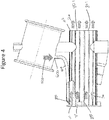
Figure 4 depicts the air flow through the new ACC Valve. -
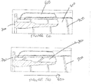
Figure 5a depicts a cut-away view of a new ACC Valve showing a first rib configuration. -
Figure 5b depicts a cut-away view of a new ACC Valve showing a second rib configuration. - The examples described herein aim to provide an ACC Valve with improved heat dissipation. The valves described herein may be used for air distribution and airflow control. Both require thermal management due to the requirements of operating at high temperatures.
- Although applicable to ACCV for any kind of aircraft, the examples described herein may be also utilized in other valves that are configured to air distribution and air flow control. Further, the examples may be used in various types of ACC (Active Clearance Control) valves, such as hydraulic and electric powered, to manage air transportation.
- The ACC Valve 10 shown in
figure 1 is a known ACC Valve made by conventional methods. Thevalve housing 70 is formed and then later covered by a separate layer of material that is wrapped around the valve housing and acts as a thermal shield.Thermal shields 20 that are currently used in ACC Valves are made of a heat insulation material such as aluminium foil. Separate pieces of thethermal shield 20 are attached to the housing of the ACC Valve 10 by suitable means such as lock wire and capstans (not shown). - It would be advantageous, however, if a method of making these ACC Valves could be improved so that costs were reduced, the valves required less overall maintenance and durability of the valve was improved.
- The new method and ACC Valves described herein therefore aim to achieve these advantages over known methods to produce a ACC Valves that also have superior qualities in terms of cost, function, weight and ease of maintenance and manufacture.
- In the new examples of ACC Valves as described herein, the ACC Valves are made by forming the valve housing and its shield as one component via an additive manufacturing method. The valve housing of any of the new examples described herein may be formed from Ti6-4 material. The shield is formed via additive manufacturing methods so that it is provided externally to the valve housing and in some examples is integrated with the valve housing via ribs. The ACC Valve may also be formed so that a cooling passage or passages is/are provided between the valve housing and the thermal shield. In some examples, these channels are formed via the ribs.
- An advantage of using additive manufacturing methods is that it allows for this cooling channel or channels to be provided within an intermediate space that is defined between the outer shield and the inner housing. The cooling channels that are provided within the intermediate space are configured to efficiently reduce the temperature of the valve. Such cooling channels may be used to transport a cooling medium such as air, fluid or other suitable medium. When the cooling medium is air, then the cooling medium may be taken directly from an air distribution system.
- For example,
figure 2 depicts a new type of ACC Valve 100 that has been produced via an additive manufacturing method. The valve 100 has a valve housing 700 (which may in some examples be comprised of both a main valve housing and an actuator housing) and athermal shield 200 is provided via an additive manufacturing method so that both thehousing 700 and thethermal shield 200 are formed integrally as one component. - In some examples, the
valve housing 700 andthermal shield 200 may be formed so as to provide a space or spaces between the outer surface of thehousing 700 and the inner surface of the surroundingthermal shield 200, as described above. In such examples, and as shown infigure 2 , the valve 100 may also have a coolingmedium inlet orifice 600 that is fluidly connected to this intermediate space between thehousing 700 and shield 200 so as to allow the cooling medium to be drawn into the space that is provided between these components. In some examples, the cooling medium is air, or a gas, and in other examples, the cooling medium may be a liquid. -
Figure 3 shows a side view of the ACC Valve 100 offigure 2 depicting the movement of the cooling medium 500 as it passed through and into the valve and also into theorifice 600. From there thecooling medium 500 is able to pass into the intermediate space, i.e. the cooling channel(s) 800 that are formed between the outer surface of the valve housing 100 and the inner surface of thethermal shield 200. - As can be seen in
figure 3 , anair cooling channel 800 in this example is connected via atubing 610 to theair inlet orifice 600. In the example shown infigure 3 , the coolingchannel 800 then extends helically around the outer surface of the valve housing 100 from a first end 10 to asecond end 102 of the housing. In some examples, the coolingchannels 800 may extend along only part of the full length/outer surface of the valve, and in other examples, the channels may cover the entire surface of the valve housing. - In the example shown in
figure 4 , the coolingchannels 800 extend in a straight line and longitudinally between thefirst end 101 and thesecond end 102. That is, as in the example shown infigure 3 , the cooling medium 500 is able to enter into the coolingchannel 800 at thefirst end 101 of the valve and then flow from thefirst end 101 to thesecond end 102, where it exits the channel(s) 800 via the particular configuration of thechannel 800 orchannels 800. A cooling medium outlet or outlet(s) 801 is/are provided, in this example, at thesecond end 102 of the valve housing. -
Figures 5a and 5b depict cut away views of avalve housing 700 such as that shown infigures 3 and4 wherein the coolingchannels 800 have different internal configurations and shapes. In some examples, the printing may be achieved by printing the in thedirection 650 as shown infigure 5b . - In some examples, these cooling
channels 800 may be formed by printing thethermal shield 200 so as to provide it withribs 900 as shown in these figures. In some examples, the method may comprise arranging thethermal shield 200 around the external surface of the housing component and printing theribs 900 onto thethermal shield 200 to thereby form these coolingchannels 800 between thevalve housing 700 and thethermal shield 200. - In some examples, the ribs' 900 geometry can be extended along the housing component in different ways to create these specific
internal cooling channels 800 so that their configuration is provided for maximum cooling efficiency. The main function of the coolingchannels 800 is to redirect the cool air taken directly from valve flow. Due to this, the coolingchannels 800 will improve the thermal management of ACCV 100. - In addition to this, by providing
rigid ribs 900, the overall product durability is improved and external damage is prevented. In the same way as for known ACCVs, the main function of the printedthermal shield 200 is to block and to dissipate the heat, similar to a heat exchanger; however, by printing theshield 200 with theseribs 900, the shield is therefore not only able to protect thevalve housing 700 from fire and damage but is also able to facilitate an active cooling by using the airflow (i.e. via the cooling channels 800). - The new method and ACCV described herein uses an additive manufacturing (AM) process for making this new ACCV product 100. Unlike known methods for making ACCVs the method described herein provides an ACC Valve that is integrated with the thermal shield so that it is one printed part that is made of Ti6-4 via an AM process.
- Printing the components of the valve and shield as one part provides many benefits in terms of ease of manufacture and costs.
- The new method described herein uses an AM to print the
thermal shield 200 so that thethermal shield 200 is integrated with theACCV housing 700. - The method therefore comprises forming an
ACC valve housing 700 and athermal shield 200 via an AM method so that thethermal shield 200 is provided externally to thevalve housing 700. - The benefits of manufacturing the new type of ACCV 100 in this way also includes a reduction in manufacturing costs. The fact that the
thermal shield 200 is printed together with the housing component as a single part eliminates the need for a separate manufacture of the thermal shield assembly and installation. The new method described herein also results in a reduction in service and maintenance costs, since there is no need for a fire shield disassembly/assembly prior to putting the product back into service. In addition to this, the method results in an ACCV 100 with improved durability, since the rigid printed metallicthermal shield 200 will protect the critical components of the ACCV 100 from excessive heat and external damages. A further advantage is that the overall weight of the ACCV 100 produced via this method is reduced. - In summary, a shielded valve is described herein that provides thermal management for an air distribution system. In particular, the examples described herein provide an ACCV that has improved thermal management of air distribution and control valves, to thereby improve valve protection against high surrounding temperatures and short time exposure to fire.
Claims (13)
- An active clearance control valve (ACC Valve) (100) comprising a valve housing (700) with a thermal shield (200) provided externally to said housing (700), wherein said valve housing (700) and said thermal shield (200) have been integrally formed as one component.
- The ACC Valve of claim 1 wherein said valve housing (700) and said thermal shield (200) have been integrally formed via an additive manufacturing method.
- The ACC Valve of any of claims 1 or 2 wherein said thermal shield (200) comprises a rib or ribs (900) provided thereon and/or therein.
- The ACC Valve of any preceding claim wherein a first cooling channel (800) is provided so as to extend between said valve housing (700) and said thermal shield (200).
- The ACC Valve of any of claims 1 or 2 wherein said thermal shield (200) comprises a rib or ribs (900) provided thereon and/or therein, said ribs thereby forming said first cooling channel (800) that extends between said valve housing (700) and said thermal shield (200).
- The ACC Valve of any of claims 4 or 5 wherein said first cooling channel (800) is provided so as to extend helically between a first end (101) of the valve housing (700) to a second end (102) of the valve housing (700).
- The ACC Valve of any of claims 4 or 5 wherein said first cooling channel (800) is provided so as to extend longitudinally between a first end (101) of the valve housing (700) to a second end (102) of the valve housing (700).
- The ACC Valve of any of claims 3, 5 or 6 wherein said rib or ribs (900) are provided so as to extend helically between a first end (101) of the valve housing (700) to a second end (102) of the valve housing (700).
- The ACC Valve of any of claims 3, 5 or 7 wherein said rib or ribs (900) are provided so as to extend longitudinally between a first end (101) of the valve housing (700) to a second end (102) of the valve housing (700).
- A method of making an ACCV (100) comprising
integrally forming, as one component, a valve housing (700) and a thermal shield (200) external to said housing (700). - The method of claim 10 comprising integrally forming said valve housing (700) and said thermal shield (200) via an additive manufacturing method.
- The method of claim 10 or 11 further comprising printing a rib or ribs (900) onto said thermal shield.
- The method of any of claims 11 to 12 further comprising forming a cooling channel or channels (800) between said valve housing (700) and said thermal shield (200).
Priority Applications (2)
| Application Number | Priority Date | Filing Date | Title |
|---|---|---|---|
| EP18461581.3A EP3597874A1 (en) | 2018-07-19 | 2018-07-19 | Active clearance control valve with thermal shield and method for manufacturing the same |
| US16/384,161 US11306842B2 (en) | 2018-07-19 | 2019-04-15 | ACCV and a method for manufacturing the same |
Applications Claiming Priority (1)
| Application Number | Priority Date | Filing Date | Title |
|---|---|---|---|
| EP18461581.3A EP3597874A1 (en) | 2018-07-19 | 2018-07-19 | Active clearance control valve with thermal shield and method for manufacturing the same |
Publications (1)
| Publication Number | Publication Date |
|---|---|
| EP3597874A1 true EP3597874A1 (en) | 2020-01-22 |
Family
ID=63014481
Family Applications (1)
| Application Number | Title | Priority Date | Filing Date |
|---|---|---|---|
| EP18461581.3A Pending EP3597874A1 (en) | 2018-07-19 | 2018-07-19 | Active clearance control valve with thermal shield and method for manufacturing the same |
Country Status (2)
| Country | Link |
|---|---|
| US (1) | US11306842B2 (en) |
| EP (1) | EP3597874A1 (en) |
Families Citing this family (5)
| Publication number | Priority date | Publication date | Assignee | Title |
|---|---|---|---|---|
| US11885240B2 (en) | 2021-05-24 | 2024-01-30 | General Electric Company Polska sp.z o.o | Gas turbine engine with fluid circuit and ejector |
| US11859500B2 (en) | 2021-11-05 | 2024-01-02 | General Electric Company | Gas turbine engine with a fluid conduit system and a method of operating the same |
| US11719115B2 (en) | 2021-11-05 | 2023-08-08 | General Electric Company | Clearance control structure for a gas turbine engine |
| US11788425B2 (en) | 2021-11-05 | 2023-10-17 | General Electric Company | Gas turbine engine with clearance control system |
| CN116085067A (en) | 2021-11-05 | 2023-05-09 | 通用电气公司 | Gas turbine engine with fluid conduit system and method of operating the same |
Citations (6)
| Publication number | Priority date | Publication date | Assignee | Title |
|---|---|---|---|---|
| CN201610943U (en) * | 2010-03-03 | 2010-10-20 | 郑州华泰特阀有限公司 | Temperature preservation jacketed valve and temperature preservation valve body thereof |
| US7874310B1 (en) * | 2002-06-18 | 2011-01-25 | Jansen's Aircraft Systems Controls, Inc. | Water cooled liquid fuel valve |
| US20120167862A1 (en) * | 2009-11-18 | 2012-07-05 | Mitsubishi Electric Corporation | Drop-in type of exhaust gas recirculation valve, and system for attaching same |
| US20130283815A1 (en) * | 2012-04-26 | 2013-10-31 | Hamilton Sundstrand Corporation | Integral cooling for servo valve |
| WO2013178442A1 (en) * | 2012-05-29 | 2013-12-05 | Pierburg Gmbh | Control valve for installing on an internal combustion engine |
| EP3159493A1 (en) * | 2015-10-23 | 2017-04-26 | General Electric Company | Active clearance control with integral double wall heat shielding |
Family Cites Families (10)
| Publication number | Priority date | Publication date | Assignee | Title |
|---|---|---|---|---|
| US138562A (en) * | 1873-05-06 | Improvement in hydrants | ||
| US1727659A (en) * | 1927-07-14 | 1929-09-10 | American Car & Foundry Co | Discharge outlet |
| US9598974B2 (en) * | 2013-02-25 | 2017-03-21 | Pratt & Whitney Canada Corp. | Active turbine or compressor tip clearance control |
| US20150048209A1 (en) | 2013-08-16 | 2015-02-19 | Robert Hoyt | Structures with Internal Microstructures to Provide Multifunctional Capabilities |
| US10100729B2 (en) * | 2015-01-19 | 2018-10-16 | Hamilton Sundstrand Corporation | Cooling device for electro-pneumatic controller |
| EP3075471B1 (en) | 2015-03-30 | 2021-11-03 | MTU Aero Engines AG | Method of production of a gas turbine housing section by additive manufacturing |
| EP3086011B1 (en) | 2015-04-21 | 2019-07-31 | Airbus Operations GmbH | Double-walled pipe with integrated heating capability for an aircraft or spacecraft |
| US20170081250A1 (en) | 2015-09-17 | 2017-03-23 | Siemens Energy, Inc. | Method of forming a thermal barrier coating having a porosity architecture using additive manufacturing |
| US11306578B2 (en) * | 2018-04-16 | 2022-04-19 | Baker Hughes, A Ge Company, Llc | Thermal barrier for downhole flasked electronics |
| US20190331009A1 (en) * | 2018-04-25 | 2019-10-31 | Ford Global Technologies, Llc | Internally cooled valve guide |
-
2018
- 2018-07-19 EP EP18461581.3A patent/EP3597874A1/en active Pending
-
2019
- 2019-04-15 US US16/384,161 patent/US11306842B2/en active Active
Patent Citations (6)
| Publication number | Priority date | Publication date | Assignee | Title |
|---|---|---|---|---|
| US7874310B1 (en) * | 2002-06-18 | 2011-01-25 | Jansen's Aircraft Systems Controls, Inc. | Water cooled liquid fuel valve |
| US20120167862A1 (en) * | 2009-11-18 | 2012-07-05 | Mitsubishi Electric Corporation | Drop-in type of exhaust gas recirculation valve, and system for attaching same |
| CN201610943U (en) * | 2010-03-03 | 2010-10-20 | 郑州华泰特阀有限公司 | Temperature preservation jacketed valve and temperature preservation valve body thereof |
| US20130283815A1 (en) * | 2012-04-26 | 2013-10-31 | Hamilton Sundstrand Corporation | Integral cooling for servo valve |
| WO2013178442A1 (en) * | 2012-05-29 | 2013-12-05 | Pierburg Gmbh | Control valve for installing on an internal combustion engine |
| EP3159493A1 (en) * | 2015-10-23 | 2017-04-26 | General Electric Company | Active clearance control with integral double wall heat shielding |
Also Published As
| Publication number | Publication date |
|---|---|
| US20200025304A1 (en) | 2020-01-23 |
| US11306842B2 (en) | 2022-04-19 |
Similar Documents
| Publication | Publication Date | Title |
|---|---|---|
| US11306842B2 (en) | ACCV and a method for manufacturing the same | |
| CA2743279C (en) | Cooler in nacelle with radial coolant | |
| US8387362B2 (en) | Method and apparatus for operating gas turbine engine heat exchangers | |
| US11168583B2 (en) | Systems and methods for cooling components within a gas turbine engine | |
| US11448130B2 (en) | Multiple stream heat exchanger | |
| US8784047B2 (en) | Gas turbine engine heat exchanger with tapered fins | |
| US10697371B2 (en) | Method and system for a combined air-oil cooler and fuel-oil cooler heat exchanger | |
| US10145253B2 (en) | Stator vane formed by a set of vane parts | |
| CN107849980B (en) | Turbine engine with anti-icing valve assembly, bleed valve and method of operation | |
| US8763363B2 (en) | Method and system for cooling fluid in a turbine engine | |
| EP4043715B1 (en) | Fluid cooler installation and method for turbofan engine | |
| CN110892140B (en) | Aircraft propulsion assembly including air-to-liquid heat exchanger | |
| US20200200040A1 (en) | Aircraft surface cooler assembly | |
| US20170184026A1 (en) | System and method of soakback mitigation through passive cooling | |
| WO2018084943A1 (en) | Cooled combustor case with over-pressurized cooling air | |
| EP3239476A1 (en) | Case clearance control system and corresponding gas turbine engines | |
| US10794215B2 (en) | Cooling arrangement for a turbine casing of a gas turbine engine | |
| EP3070265B1 (en) | Vane | |
| US20200332712A1 (en) | Compact multi-pass heat exchanger | |
| CN114787495A (en) | Heat exchanger comprising a partition wall of blades provided with a recessed turbulence generator | |
| US11274602B2 (en) | Air cooler for gas turbine engine | |
| US12104537B1 (en) | Engine accessory fire shield | |
| CN115362314B (en) | Retractable gas-to-oil heat exchanger for an aircraft propulsion assembly | |
| GB2496852A (en) | Heat exchanger with tapered fins for a gas turbine |
Legal Events
| Date | Code | Title | Description |
|---|---|---|---|
| PUAI | Public reference made under article 153(3) epc to a published international application that has entered the european phase |
Free format text: ORIGINAL CODE: 0009012 |
|
| STAA | Information on the status of an ep patent application or granted ep patent |
Free format text: STATUS: THE APPLICATION HAS BEEN PUBLISHED |
|
| AK | Designated contracting states |
Kind code of ref document: A1 Designated state(s): AL AT BE BG CH CY CZ DE DK EE ES FI FR GB GR HR HU IE IS IT LI LT LU LV MC MK MT NL NO PL PT RO RS SE SI SK SM TR |
|
| AX | Request for extension of the european patent |
Extension state: BA ME |
|
| STAA | Information on the status of an ep patent application or granted ep patent |
Free format text: STATUS: REQUEST FOR EXAMINATION WAS MADE |
|
| 17P | Request for examination filed |
Effective date: 20200721 |
|
| RBV | Designated contracting states (corrected) |
Designated state(s): AL AT BE BG CH CY CZ DE DK EE ES FI FR GB GR HR HU IE IS IT LI LT LU LV MC MK MT NL NO PL PT RO RS SE SI SK SM TR |
|
| STAA | Information on the status of an ep patent application or granted ep patent |
Free format text: STATUS: EXAMINATION IS IN PROGRESS |
|
| 17Q | First examination report despatched |
Effective date: 20220704 |