EP3597871A1 - Environmental barrier multi-phase abradable coating - Google Patents
Environmental barrier multi-phase abradable coating Download PDFInfo
- Publication number
- EP3597871A1 EP3597871A1 EP19183339.1A EP19183339A EP3597871A1 EP 3597871 A1 EP3597871 A1 EP 3597871A1 EP 19183339 A EP19183339 A EP 19183339A EP 3597871 A1 EP3597871 A1 EP 3597871A1
- Authority
- EP
- European Patent Office
- Prior art keywords
- phase
- coating
- ceramic matrix
- coating system
- abradable coating
- Prior art date
- Legal status (The legal status is an assumption and is not a legal conclusion. Google has not performed a legal analysis and makes no representation as to the accuracy of the status listed.)
- Granted
Links
Images


Classifications
-
- F—MECHANICAL ENGINEERING; LIGHTING; HEATING; WEAPONS; BLASTING
- F01—MACHINES OR ENGINES IN GENERAL; ENGINE PLANTS IN GENERAL; STEAM ENGINES
- F01D—NON-POSITIVE DISPLACEMENT MACHINES OR ENGINES, e.g. STEAM TURBINES
- F01D11/00—Preventing or minimising internal leakage of working-fluid, e.g. between stages
- F01D11/08—Preventing or minimising internal leakage of working-fluid, e.g. between stages for sealing space between rotor blade tips and stator
- F01D11/12—Preventing or minimising internal leakage of working-fluid, e.g. between stages for sealing space between rotor blade tips and stator using a rubstrip, e.g. erodible. deformable or resiliently-biased part
- F01D11/122—Preventing or minimising internal leakage of working-fluid, e.g. between stages for sealing space between rotor blade tips and stator using a rubstrip, e.g. erodible. deformable or resiliently-biased part with erodable or abradable material
-
- C—CHEMISTRY; METALLURGY
- C04—CEMENTS; CONCRETE; ARTIFICIAL STONE; CERAMICS; REFRACTORIES
- C04B—LIME, MAGNESIA; SLAG; CEMENTS; COMPOSITIONS THEREOF, e.g. MORTARS, CONCRETE OR LIKE BUILDING MATERIALS; ARTIFICIAL STONE; CERAMICS; REFRACTORIES; TREATMENT OF NATURAL STONE
- C04B41/00—After-treatment of mortars, concrete, artificial stone or ceramics; Treatment of natural stone
- C04B41/009—After-treatment of mortars, concrete, artificial stone or ceramics; Treatment of natural stone characterised by the material treated
-
- C—CHEMISTRY; METALLURGY
- C04—CEMENTS; CONCRETE; ARTIFICIAL STONE; CERAMICS; REFRACTORIES
- C04B—LIME, MAGNESIA; SLAG; CEMENTS; COMPOSITIONS THEREOF, e.g. MORTARS, CONCRETE OR LIKE BUILDING MATERIALS; ARTIFICIAL STONE; CERAMICS; REFRACTORIES; TREATMENT OF NATURAL STONE
- C04B41/00—After-treatment of mortars, concrete, artificial stone or ceramics; Treatment of natural stone
- C04B41/45—Coating or impregnating, e.g. injection in masonry, partial coating of green or fired ceramics, organic coating compositions for adhering together two concrete elements
- C04B41/52—Multiple coating or impregnating multiple coating or impregnating with the same composition or with compositions only differing in the concentration of the constituents, is classified as single coating or impregnation
-
- C—CHEMISTRY; METALLURGY
- C04—CEMENTS; CONCRETE; ARTIFICIAL STONE; CERAMICS; REFRACTORIES
- C04B—LIME, MAGNESIA; SLAG; CEMENTS; COMPOSITIONS THEREOF, e.g. MORTARS, CONCRETE OR LIKE BUILDING MATERIALS; ARTIFICIAL STONE; CERAMICS; REFRACTORIES; TREATMENT OF NATURAL STONE
- C04B41/00—After-treatment of mortars, concrete, artificial stone or ceramics; Treatment of natural stone
- C04B41/80—After-treatment of mortars, concrete, artificial stone or ceramics; Treatment of natural stone of only ceramics
- C04B41/81—Coating or impregnation
- C04B41/89—Coating or impregnation for obtaining at least two superposed coatings having different compositions
-
- F—MECHANICAL ENGINEERING; LIGHTING; HEATING; WEAPONS; BLASTING
- F05—INDEXING SCHEMES RELATING TO ENGINES OR PUMPS IN VARIOUS SUBCLASSES OF CLASSES F01-F04
- F05D—INDEXING SCHEME FOR ASPECTS RELATING TO NON-POSITIVE-DISPLACEMENT MACHINES OR ENGINES, GAS-TURBINES OR JET-PROPULSION PLANTS
- F05D2240/00—Components
- F05D2240/10—Stators
- F05D2240/11—Shroud seal segments
-
- F—MECHANICAL ENGINEERING; LIGHTING; HEATING; WEAPONS; BLASTING
- F05—INDEXING SCHEMES RELATING TO ENGINES OR PUMPS IN VARIOUS SUBCLASSES OF CLASSES F01-F04
- F05D—INDEXING SCHEME FOR ASPECTS RELATING TO NON-POSITIVE-DISPLACEMENT MACHINES OR ENGINES, GAS-TURBINES OR JET-PROPULSION PLANTS
- F05D2300/00—Materials; Properties thereof
- F05D2300/10—Metals, alloys or intermetallic compounds
- F05D2300/15—Rare earth metals, i.e. Sc, Y, lanthanides
-
- F—MECHANICAL ENGINEERING; LIGHTING; HEATING; WEAPONS; BLASTING
- F05—INDEXING SCHEMES RELATING TO ENGINES OR PUMPS IN VARIOUS SUBCLASSES OF CLASSES F01-F04
- F05D—INDEXING SCHEME FOR ASPECTS RELATING TO NON-POSITIVE-DISPLACEMENT MACHINES OR ENGINES, GAS-TURBINES OR JET-PROPULSION PLANTS
- F05D2300/00—Materials; Properties thereof
- F05D2300/20—Oxide or non-oxide ceramics
- F05D2300/21—Oxide ceramics
- F05D2300/211—Silica
-
- F—MECHANICAL ENGINEERING; LIGHTING; HEATING; WEAPONS; BLASTING
- F05—INDEXING SCHEMES RELATING TO ENGINES OR PUMPS IN VARIOUS SUBCLASSES OF CLASSES F01-F04
- F05D—INDEXING SCHEME FOR ASPECTS RELATING TO NON-POSITIVE-DISPLACEMENT MACHINES OR ENGINES, GAS-TURBINES OR JET-PROPULSION PLANTS
- F05D2300/00—Materials; Properties thereof
- F05D2300/20—Oxide or non-oxide ceramics
- F05D2300/21—Oxide ceramics
- F05D2300/2118—Zirconium oxides
-
- F—MECHANICAL ENGINEERING; LIGHTING; HEATING; WEAPONS; BLASTING
- F05—INDEXING SCHEMES RELATING TO ENGINES OR PUMPS IN VARIOUS SUBCLASSES OF CLASSES F01-F04
- F05D—INDEXING SCHEME FOR ASPECTS RELATING TO NON-POSITIVE-DISPLACEMENT MACHINES OR ENGINES, GAS-TURBINES OR JET-PROPULSION PLANTS
- F05D2300/00—Materials; Properties thereof
- F05D2300/60—Properties or characteristics given to material by treatment or manufacturing
- F05D2300/603—Composites; e.g. fibre-reinforced
- F05D2300/6033—Ceramic matrix composites [CMC]
Definitions
- Exemplary embodiments of the present disclosure pertain to the art of abradable coatings for ceramic matrix composites (CMC).
- CMC ceramic matrix composites
- a shroud is a ring of material surrounding rotating blades. Turbine performance and efficiency may be enhanced by reducing the space between the tip of the rotating blade and the stationary shroud to limit the flow of air over or around the top of the blade that would otherwise bypass the blade.
- a blade may be configured so that its tip fits close to the shroud during engine operation. Thus, generating and maintaining an efficient tip clearance is desired for efficiency purposes.
- an environmental barrier coating (EBC) is required for successful performance/survival of the part.
- an abradable layer is deposited on top of the EBC to protect it from blade rub. In some cases the abradable coating is depleted by the initial engine burn in. Thus, an improved abradable coating for a CMC component such as a shroud is desired.
- a multi-phase abradable coating (e.g. for use in a coating system as disclosed herein) including a ceramic matrix and a dislocator phase.
- the dislocator phase may include zircon, ZrO 2 or a combination thereof.
- the multi-phase abradable coating includes ZrO 2 . At least a portion of the ZrO 2 may be cracked, e.g. micro-cracked.
- the ceramic matrix includes hafnium dioxide, a rare earth disilicate, a rare earth monosilicate, hafnium silicate, BSAS (BaO 1-x -SrO x -Al 2 O 3 -2SiO 2 ), or a combination thereof.
- a coating system on a ceramic matrix composite component including a multi-phase abradable coating (e.g. as disclosed herein) in combination with a top coat, a bond coat or a combination thereof.
- the multi-phase abradable coating includes a ceramic matrix and a dislocator phase.
- a ceramic matrix composite component coated with a coating system including a multi-phase abradable coating (e.g. as disclosed herein) in combination with a top coat, a bond coat or a combination thereof.
- the multi-phase abradable coating includes a ceramic matrix and a dislocator phase.
- the dislocator phase includes zircon, ZrO 2 or a combination thereof.
- the multi-phase abradable coating includes ZrO 2 . At least a portion of the ZrO 2 may be cracked, e.g. micro-cracked.
- the ceramic matrix includes hafnium dioxide, a rare earth disilicate, a rare earth monosilicate, hafnium silicate, BSAS (BaO 1-x -SrO x -Al 2 O 3 -2SiO 2 ), or a combination thereof.
- the ceramic matrix includes hafnium dioxide, a rare earth disilicate, or a combination thereof.
- the coating system includes a top coat and a bond coat and further wherein the bond coat is disposed on the ceramic matrix component and the top coat is disposed between the bond coat and the multi-phase abradable coating.
- the coating system includes a top coat disposed between the ceramic matrix component and the multi-phase abradable coating.
- the coating system includes a bond coat disposed between the ceramic matrix component and the multi-phase abradable coating.
- the bond coat includes silicon.
- the top coat includes hafnium dioxide, a rare earth disilicate, or a combination thereof.
- the top coat and the ceramic matrix include the same material.
- the ceramic matrix composite component (e.g. as disclosed herein) is a shroud for the turbine section of a gas turbine engine.
- FIG. 1 schematically illustrates a gas turbine engine 20.
- the gas turbine engine 20 is disclosed herein as a two-spool turbofan that generally incorporates a fan section 22, a compressor section 24, a combustor section 26 and a turbine section 28.
- Alternative engines might include other systems or features.
- the fan section 22 drives air along a bypass flow path B in a bypass duct, while the compressor section 24 drives air along a core flow path C for compression and communication into the combustor section 26 then expansion through the turbine section 28.
- FIG. 1 schematically illustrates a gas turbine engine 20.
- the gas turbine engine 20 is disclosed herein as a two-spool turbofan that generally incorporates a fan section 22, a compressor section 24, a combustor section 26 and a turbine section 28.
- Alternative engines might include other systems or features.
- the fan section 22 drives air along a bypass flow path B in a bypass duct
- the compressor section 24 drives air along a core flow path C for compression and communication into the combustor section 26
- the exemplary engine 20 generally includes a low speed spool 30 and a high speed spool 32 mounted for rotation about an engine central longitudinal axis A relative to an engine static structure 36 via several bearing systems 38. It should be understood that various bearing systems 38 at various locations may alternatively or additionally be provided, and the location of bearing systems 38 may be varied as appropriate to the application.
- the low speed spool 30 generally includes an inner shaft 40 that interconnects a fan 42, a low pressure compressor 44 and a low pressure turbine 46.
- the inner shaft 40 is connected to the fan 42 through a speed change mechanism, which in exemplary gas turbine engine 20 is illustrated as a geared architecture 48 to drive the fan 42 at a lower speed than the low speed spool 30.
- the high speed spool 32 includes an outer shaft 50 that interconnects a high pressure compressor 52 and high pressure turbine 54.
- a combustor 56 is arranged in exemplary gas turbine 20 between the high pressure compressor 52 and the high pressure turbine 54.
- An engine static structure 36 is arranged generally between the high pressure turbine 54 and the low pressure turbine 46.
- the engine static structure 36 further supports bearing systems 38 in the turbine section 28.
- the inner shaft 40 and the outer shaft 50 are concentric and rotate via bearing systems 38 about the engine central longitudinal axis A which is collinear with their longitudinal axes.
- each of the positions of the fan section 22, compressor section 24, combustor section 26, turbine section 28, and fan drive gear system 48 may be varied.
- gear system 48 may be located aft of combustor section 26 or even aft of turbine section 28, and fan section 22 may be positioned forward or aft of the location of gear system 48.
- the turbine section 28 includes a shroud having an abradable coating system disposed on a ceramic matrix composite substrate.
- the abradable coating system includes a multi-phase abradable coating with a top coat, a bond coat or both a top coat and a bond coat.
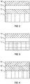
- FIG. 2 shows a coating system having a multi-phase abradable coating 14 disposed on a top coat 13. Top coat 13 is disposed on a bond coat 12. Bond coat 12 is disposed on CMC substrate 11.
- the coating system as shown in FIG. 3 , may have a multi-phase abradable coating 14 disposed on top coat 13, which is, in turn, disposed on CMC substrate 11.
- the coating system as shown in FIG. 4 , includes a multi-phase abradable coating 14 disposed on bond coat 12, which is, in turn, disposed on CMC substrate 11.
- the multi-phase abradable coating includes a dislocator phase dispersed in a ceramic matrix.
- the dislocator phase transforms to a cracked, e.g. micro-cracked, phase through exposure to a combustion gas atmosphere. This allows the uppermost portion of the multi-phase abradable coating to be abradable while the lower portion of the multi-phase abradable coating (the portion closest to the CMC) remains in its as deposited form.
- the dislocator phase includes zircon (ZrSiO 4 )
- exposure to a post combustion atmosphere converts the zircon closest to the exposed surface of the multi-phase abradable coating to ZrO 2 because Si(OH) 4 vaporizes from the exposed surface.
- the ZrO 2 undergoes a phase change between tetragonal and monoclinic during normal thermal cycling of the turbine engine and the volume change associated with the phase change results in at least a portion of the ZrO 2 becoming cracked, e.g. micro-cracked, ZrO 2 .
- the presence of cracked, e.g. micro-cracked, ZrO 2 results in an abradable material. It is also contemplated that the ZrO 2 can be deposited as part of the coating.
- FIG. 5 An embodiment of the as-deposited multi-phase abradable coating is shown in FIG. 5.
- FIG. 5 shows the ceramic matrix 120, the ZrSiO 4 dislocator phase 122 and pores 124.
- the multi-phase abradable coating after exposure to a post combustion atmosphere is shown in FIG. 6.
- FIG. 6 shows micro-cracked ZrO 2 126 near the surface where previously ZrSiO 4 was located.
- FIG. 6 shows that the multi-phase abradable coating retains ZrSiO 4 122 in the interior of the coating.
- the multi-phase abradable coating includes a ceramic matrix.
- Exemplary ceramic matrices include hafnium dioxide, rare earth disilicates, rare earth monosilicates, hafnium silicate, BSAS (BaO 1-x -SrO x -Al 2 O 3 -2SiO 2 ), and combinations thereof.
- Rare earth metals include cerium, dysprosium, erbium, europium, gadolinium, holmium, lanthanium, lutetium, neodymium, praseodymium, promethium, samarium, terbium, thulium, ytterbium, and yttrium.
- Exemplary rare earth disilicates include yttrium-ytterbium disilicate (YbYDS), ytterbium disilicate (YbDS), lutetium disilicate (LuDS), thulium disilicate (TmDS), lutetium yttrium disilicate (LuYDS), thulium yttrium disilicate (TmYDS) and combinations thereof.
- the ceramic matrix is chosen to have a coefficient of thermal expansion similar to that of the CMC.
- the multi-phase abradable coating may have a thickness of 2 to 50 mils, or, more specifically, 5 to 20 mils.
- the multi-phase abradable coating may have a porosity of 1 to 20%, or, more specifically, 5 to 10%.
- the as-deposited multi-phase abradable coating may have a dislocator phase content of 5 to 25 vol%, or, more specifically, 1 to 20 vol%.
- the multi-phase abradable coating may be deposited by a thermal spray method such as plasma spray. It is contemplated that plasma spray conditions may convert some or all of the dislocator phase (such as zircon) to the precursor to the cracked, e.g. micro-cracked, phase (such as ZrO 2 ) and a heat treatment would be required to reform the dislocator phase prior to exposure to a post combustion atmosphere.
- the top coat when present, includes hafnium dioxide, a rare earth disilicate (as described above) or a combination thereof.
- the top coat may have a thickness of 2 to 12 mils, or, more specifically, 4 to 8 mils.
- the top coat may have a porosity which is less than that of the multi-phase abradable coating.
- the top coat is free of the dislocator phase.
- the top coat may be deposited by slurry deposition or air plasma spray.
- the bond coat when present, may include silicon.
- Exemplary bond coats include those having a barium-magnesium alumino silicate matrix and dispersed particles as described in US Patent Publication No. 2016/0332922 , silicon oxycarbide as described in U.S. Patent Publication No. 2012/0328886 , and a combination of silicon oxycarbide and calcium magnesium alumino silicate as described in U.S. Patent Publication No. 2016/0333454 , all of which are incorporated by reference herein
- the bond coat may oxidize in service to form a silicon oxide layer positioned between the bond coat and the layer above it (either the top coat or the multi-phase abradable coating).
- the bond coat may have a thickness of 2 to 15 mils, or, more specifically, 5 to 10 mils.
- the bond coat may have a porosity of 0 to 20%, or, more specifically, 1 to 5%.
Landscapes
- Engineering & Computer Science (AREA)
- Chemical & Material Sciences (AREA)
- Ceramic Engineering (AREA)
- Materials Engineering (AREA)
- Structural Engineering (AREA)
- Organic Chemistry (AREA)
- Mechanical Engineering (AREA)
- General Engineering & Computer Science (AREA)
- Coating By Spraying Or Casting (AREA)
- Turbine Rotor Nozzle Sealing (AREA)
Abstract
Description
- Exemplary embodiments of the present disclosure pertain to the art of abradable coatings for ceramic matrix composites (CMC).
- Within a turbine engine, a shroud is a ring of material surrounding rotating blades. Turbine performance and efficiency may be enhanced by reducing the space between the tip of the rotating blade and the stationary shroud to limit the flow of air over or around the top of the blade that would otherwise bypass the blade. For example, a blade may be configured so that its tip fits close to the shroud during engine operation. Thus, generating and maintaining an efficient tip clearance is desired for efficiency purposes.
- During engine operation, the blade tips can sometimes rub against the shroud. It is desirable to have an abradable coating which can be worn away by the blade to minimize the gap between the blade and shroud without damaging the blade. Additionally, the remaining coating must remain durable and protect the underlying substrate. For CMC shrouds, an environmental barrier coating (EBC) is required for successful performance/survival of the part.
- In order to reduce the risk of coating loss, an abradable layer is deposited on top of the EBC to protect it from blade rub. In some cases the abradable coating is depleted by the initial engine burn in. Thus, an improved abradable coating for a CMC component such as a shroud is desired.
- Disclosed is a multi-phase abradable coating (e.g. for use in a coating system as disclosed herein) including a ceramic matrix and a dislocator phase.
- In addition to one or more of the features described above, or as an alternative to any of the foregoing embodiments, the dislocator phase may include zircon, ZrO2 or a combination thereof.
- In addition to one or more of the features described above, or as an alternative to any of the foregoing embodiments, the multi-phase abradable coating includes ZrO2. At least a portion of the ZrO2 may be cracked, e.g. micro-cracked.
- In addition to one or more of the features described above, or as an alternative to any of the foregoing embodiments, the ceramic matrix includes hafnium dioxide, a rare earth disilicate, a rare earth monosilicate, hafnium silicate, BSAS (BaO1-x-SrOx-Al2O3-2SiO2), or a combination thereof.
- Also disclosed is a coating system on a ceramic matrix composite component including a multi-phase abradable coating (e.g. as disclosed herein) in combination with a top coat, a bond coat or a combination thereof. The multi-phase abradable coating includes a ceramic matrix and a dislocator phase.
- Also disclosed is a ceramic matrix composite component coated with a coating system including a multi-phase abradable coating (e.g. as disclosed herein) in combination with a top coat, a bond coat or a combination thereof. The multi-phase abradable coating includes a ceramic matrix and a dislocator phase.
- In addition to one or more of the features described above, or as an alternative to any of the foregoing embodiments, the dislocator phase includes zircon, ZrO2 or a combination thereof.
- In addition to one or more of the features described above, or as an alternative to any of the foregoing embodiments, the multi-phase abradable coating includes ZrO2. At least a portion of the ZrO2 may be cracked, e.g. micro-cracked.
- In addition to one or more of the features described above, or as an alternative to any of the foregoing embodiments, the ceramic matrix includes hafnium dioxide, a rare earth disilicate, a rare earth monosilicate, hafnium silicate, BSAS (BaO1-x-SrOx-Al2O3-2SiO2), or a combination thereof.
- In addition to one or more of the features described above, or as an alternative to any of the foregoing embodiments, the ceramic matrix includes hafnium dioxide, a rare earth disilicate, or a combination thereof.
- In addition to one or more of the features described above, or as an alternative to any of the foregoing embodiments, the coating system includes a top coat and a bond coat and further wherein the bond coat is disposed on the ceramic matrix component and the top coat is disposed between the bond coat and the multi-phase abradable coating.
- In addition to one or more of the features described above, or as an alternative to any of the foregoing embodiments, the coating system includes a top coat disposed between the ceramic matrix component and the multi-phase abradable coating.
- In addition to one or more of the features described above, or as an alternative to any of the foregoing embodiments, the coating system includes a bond coat disposed between the ceramic matrix component and the multi-phase abradable coating.
- In addition to one or more of the features described above, or as an alternative to any of the foregoing embodiments, the bond coat includes silicon.
- In addition to one or more of the features described above, or as an alternative to any of the foregoing embodiments, the top coat includes hafnium dioxide, a rare earth disilicate, or a combination thereof.
- In addition to one or more of the features described above, or as an alternative to any of the foregoing embodiments, the top coat and the ceramic matrix include the same material.
- In addition to one or more of the features described above, or as an alternative to any of the foregoing embodiments, the ceramic matrix composite component (e.g. as disclosed herein) is a shroud for the turbine section of a gas turbine engine.
- The following descriptions should not be considered limiting in any way. With reference to the accompanying drawings, like elements are numbered alike:
-
FIG. 1 is a partial cross-sectional view of a gas turbine engine; -
FIGS. 2-4 are representations of embodiments of abradable coating systems; -
FIG. 5 is a representation of an as-deposited multi-phase abradable coating; -
FIG. 6 is a representation of a multi-deposited multi-phase abradable coating after exposure to a post combustion atmosphere. - A detailed description of one or more embodiments of the disclosed coating and coating system are presented herein by way of exemplification and not limitation with reference to the Figures.
-
FIG. 1 schematically illustrates agas turbine engine 20. Thegas turbine engine 20 is disclosed herein as a two-spool turbofan that generally incorporates afan section 22, acompressor section 24, acombustor section 26 and aturbine section 28. Alternative engines might include other systems or features. Thefan section 22 drives air along a bypass flow path B in a bypass duct, while thecompressor section 24 drives air along a core flow path C for compression and communication into thecombustor section 26 then expansion through theturbine section 28. Although depicted as a two-spool turbofan gas turbine engine in the disclosed non-limiting embodiment, it should be understood that the concepts described herein are not limited to use with two-spool turbofans as the teachings may be applied to other types of turbine engines including three-spool architectures. - The
exemplary engine 20 generally includes alow speed spool 30 and ahigh speed spool 32 mounted for rotation about an engine central longitudinal axis A relative to an enginestatic structure 36 viaseveral bearing systems 38. It should be understood thatvarious bearing systems 38 at various locations may alternatively or additionally be provided, and the location ofbearing systems 38 may be varied as appropriate to the application. - The
low speed spool 30 generally includes aninner shaft 40 that interconnects afan 42, alow pressure compressor 44 and alow pressure turbine 46. Theinner shaft 40 is connected to thefan 42 through a speed change mechanism, which in exemplarygas turbine engine 20 is illustrated as a gearedarchitecture 48 to drive thefan 42 at a lower speed than thelow speed spool 30. Thehigh speed spool 32 includes anouter shaft 50 that interconnects ahigh pressure compressor 52 andhigh pressure turbine 54. Acombustor 56 is arranged inexemplary gas turbine 20 between thehigh pressure compressor 52 and thehigh pressure turbine 54. An enginestatic structure 36 is arranged generally between thehigh pressure turbine 54 and thelow pressure turbine 46. The enginestatic structure 36 further supports bearingsystems 38 in theturbine section 28. Theinner shaft 40 and theouter shaft 50 are concentric and rotate viabearing systems 38 about the engine central longitudinal axis A which is collinear with their longitudinal axes. - The core airflow is compressed by the
low pressure compressor 44 then thehigh pressure compressor 52, mixed and burned with fuel in thecombustor 56, then expanded over thehigh pressure turbine 54 andlow pressure turbine 46. Theturbines low speed spool 30 andhigh speed spool 32 in response to the expansion. It will be appreciated that each of the positions of thefan section 22,compressor section 24,combustor section 26,turbine section 28, and fandrive gear system 48 may be varied. For example,gear system 48 may be located aft ofcombustor section 26 or even aft ofturbine section 28, andfan section 22 may be positioned forward or aft of the location ofgear system 48. - As discussed above the
turbine section 28 includes a shroud having an abradable coating system disposed on a ceramic matrix composite substrate. The abradable coating system includes a multi-phase abradable coating with a top coat, a bond coat or both a top coat and a bond coat.FIG. 2 shows a coating system having a multi-phaseabradable coating 14 disposed on atop coat 13.Top coat 13 is disposed on abond coat 12.Bond coat 12 is disposed onCMC substrate 11. Alternatively, the coating system, as shown inFIG. 3 , may have a multi-phaseabradable coating 14 disposed ontop coat 13, which is, in turn, disposed onCMC substrate 11. In another embodiment the coating system, as shown inFIG. 4 , includes a multi-phaseabradable coating 14 disposed onbond coat 12, which is, in turn, disposed onCMC substrate 11. - The multi-phase abradable coating includes a dislocator phase dispersed in a ceramic matrix. The dislocator phase transforms to a cracked, e.g. micro-cracked, phase through exposure to a combustion gas atmosphere. This allows the uppermost portion of the multi-phase abradable coating to be abradable while the lower portion of the multi-phase abradable coating (the portion closest to the CMC) remains in its as deposited form. For example, when the dislocator phase includes zircon (ZrSiO4), exposure to a post combustion atmosphere converts the zircon closest to the exposed surface of the multi-phase abradable coating to ZrO2 because Si(OH)4 vaporizes from the exposed surface. Without being bound by theory, it is thought that at least a portion of the ZrO2 undergoes a phase change between tetragonal and monoclinic during normal thermal cycling of the turbine engine and the volume change associated with the phase change results in at least a portion of the ZrO2 becoming cracked, e.g. micro-cracked, ZrO2. The presence of cracked, e.g. micro-cracked, ZrO2 results in an abradable material. It is also contemplated that the ZrO2 can be deposited as part of the coating.
- An embodiment of the as-deposited multi-phase abradable coating is shown in
FIG. 5. FIG. 5 shows theceramic matrix 120, the ZrSiO4 dislocator phase 122 and pores 124. The multi-phase abradable coating after exposure to a post combustion atmosphere is shown inFIG. 6. FIG. 6 showsmicro-cracked ZrO 2 126 near the surface where previously ZrSiO4 was located.FIG. 6 shows that the multi-phase abradable coating retainsZrSiO 4 122 in the interior of the coating. - As mentioned above, the multi-phase abradable coating includes a ceramic matrix. Exemplary ceramic matrices include hafnium dioxide, rare earth disilicates, rare earth monosilicates, hafnium silicate, BSAS (BaO1-x-SrOx-Al2O3-2SiO2), and combinations thereof. Rare earth metals include cerium, dysprosium, erbium, europium, gadolinium, holmium, lanthanium, lutetium, neodymium, praseodymium, promethium, samarium, terbium, thulium, ytterbium, and yttrium. Exemplary rare earth disilicates include yttrium-ytterbium disilicate (YbYDS), ytterbium disilicate (YbDS), lutetium disilicate (LuDS), thulium disilicate (TmDS), lutetium yttrium disilicate (LuYDS), thulium yttrium disilicate (TmYDS) and combinations thereof. In general, the ceramic matrix is chosen to have a coefficient of thermal expansion similar to that of the CMC.
- The multi-phase abradable coating may have a thickness of 2 to 50 mils, or, more specifically, 5 to 20 mils. The multi-phase abradable coating may have a porosity of 1 to 20%, or, more specifically, 5 to 10%. The as-deposited multi-phase abradable coating may have a dislocator phase content of 5 to 25 vol%, or, more specifically, 1 to 20 vol%. The multi-phase abradable coating may be deposited by a thermal spray method such as plasma spray. It is contemplated that plasma spray conditions may convert some or all of the dislocator phase (such as zircon) to the precursor to the cracked, e.g. micro-cracked, phase (such as ZrO2) and a heat treatment would be required to reform the dislocator phase prior to exposure to a post combustion atmosphere.
- The top coat, when present, includes hafnium dioxide, a rare earth disilicate (as described above) or a combination thereof. The top coat may have a thickness of 2 to 12 mils, or, more specifically, 4 to 8 mils. The top coat may have a porosity which is less than that of the multi-phase abradable coating. The top coat is free of the dislocator phase. The top coat may be deposited by slurry deposition or air plasma spray.
- The bond coat, when present, may include silicon. Exemplary bond coats include those having a barium-magnesium alumino silicate matrix and dispersed particles as described in
US Patent Publication No. 2016/0332922 , silicon oxycarbide as described inU.S. Patent Publication No. 2012/0328886 , and a combination of silicon oxycarbide and calcium magnesium alumino silicate as described inU.S. Patent Publication No. 2016/0333454 , all of which are incorporated by reference herein The bond coat may oxidize in service to form a silicon oxide layer positioned between the bond coat and the layer above it (either the top coat or the multi-phase abradable coating). The bond coat may have a thickness of 2 to 15 mils, or, more specifically, 5 to 10 mils. The bond coat may have a porosity of 0 to 20%, or, more specifically, 1 to 5%. - The terminology used herein is for the purpose of describing particular embodiments only and is not intended to be limiting of the present disclosure. As used herein, the singular forms "a", "an" and "the" are intended to include the plural forms as well, unless the context clearly indicates otherwise. It will be further understood that the terms "comprises" and/or "comprising," when used in this specification, specify the presence of stated features, integers, steps, operations, elements, and/or components, but do not preclude the presence or addition of one or more other features, integers, steps, operations, element components, and/or groups thereof.
- While the present disclosure has been described with reference to an exemplary embodiment or embodiments, it will be understood by those skilled in the art that various changes may be made and equivalents may be substituted for elements thereof without departing from the scope of the present disclosure. In addition, many modifications may be made to adapt a particular situation or material to the teachings of the present disclosure without departing from the essential scope thereof. Therefore, it is intended that the present disclosure not be limited to the particular embodiment disclosed as the best mode contemplated for carrying out this present disclosure, but that the present disclosure will include all embodiments falling within the scope of the claims.
Claims (15)
- A multi-phase abradable coating comprising a ceramic matrix and a dislocator phase.
- The multi-phase abradable coating of Claim 1, wherein the dislocator phase comprises zircon, ZrO2, or a combination thereof.
- The multi-phase abradable coating of Claim 2, comprising ZrO2, wherein at least a portion of the ZrO2 is micro-cracked.
- The multi-phase abradable coating of any one of the preceding claims, wherein the ceramic matrix comprises hafnium dioxide, a rare earth disilicate, a rare earth monosilicate, BSAS, hafnium silicate, or a combination thereof.
- A coating system on a ceramic matrix composite component comprising a multi-phase abradable coating in combination with a top coat, a bond coat or a combination thereof, wherein the multi-phase abradable coating comprises a ceramic matrix and a dislocator phase.
- The coating system of Claim 5, wherein the dislocator phase comprises zircon, ZrO2, or a combination thereof.
- The coating system of Claim 6, comprising ZrO2, wherein at least a portion of the ZrO2 is micro-cracked.
- The coating system of any one of claims 5-7, wherein the ceramic matrix comprises hafnium dioxide, a rare earth disilicate or a combination thereof.
- The coating system of any one of claims 5-8, wherein the coating system comprises a top coat and a bond coat and further wherein the bond coat is disposed on the ceramic matrix component and the top coat is disposed between the bond coat and the multi-phase abradable coating.
- The coating system of any one of claims 5-9, wherein the coating system comprises a top coat disposed between the ceramic matrix component and the multi-phase abradable coating.
- The coating system of any one of claims 5-10, wherein the coating system comprises a bond coat disposed between the ceramic matrix component and the multi-phase abradable coating.
- The coating system of any one of claims 5-11, wherein the bond coat comprises silicon.
- The coating system of any one of claims 5-12, wherein the top coat comprises hafnium dioxide, a rare earth disilicate, or a combination thereof.
- The coating system of any one of claims 5-13, wherein the top coat and the ceramic matrix comprise the same material.
- The coating system of any one of claims 5-14, wherein the ceramic matrix composite component is a shroud for the turbine section of a gas turbine engine.
Applications Claiming Priority (1)
| Application Number | Priority Date | Filing Date | Title |
|---|---|---|---|
| US16/038,723 US11021989B2 (en) | 2018-07-18 | 2018-07-18 | Environmental barrier multi-phase abradable coating |
Publications (2)
| Publication Number | Publication Date |
|---|---|
| EP3597871A1 true EP3597871A1 (en) | 2020-01-22 |
| EP3597871B1 EP3597871B1 (en) | 2021-05-19 |
Family
ID=67137686
Family Applications (1)
| Application Number | Title | Priority Date | Filing Date |
|---|---|---|---|
| EP19183339.1A Active EP3597871B1 (en) | 2018-07-18 | 2019-06-28 | Environmental barrier multi-phase abradable coating |
Country Status (2)
| Country | Link |
|---|---|
| US (2) | US11021989B2 (en) |
| EP (1) | EP3597871B1 (en) |
Families Citing this family (7)
| Publication number | Priority date | Publication date | Assignee | Title |
|---|---|---|---|---|
| US11021989B2 (en) | 2018-07-18 | 2021-06-01 | Raytheon Technologies Corporation | Environmental barrier multi-phase abradable coating |
| EP3795800B1 (en) * | 2019-09-20 | 2023-03-01 | Raytheon Technologies Corporation | Sealed cmc turbine case |
| WO2022026115A1 (en) | 2020-07-03 | 2022-02-03 | Raytheon Technologies Corporation | Dislocator chemistries for turbine abradable or machinable coating systems |
| US11866379B2 (en) | 2020-08-14 | 2024-01-09 | Rtx Corporation | Hafnon and zircon environmental barrier coatings for silicon-based components |
| AU2022238864B2 (en) * | 2021-03-17 | 2024-08-22 | Oerlikon Metco (Us) Inc. | Chemically complex ceramic abradable sealant materials |
| US12312281B2 (en) * | 2022-04-01 | 2025-05-27 | Rtx Corporation | Environmental barrier coating |
| US12503953B2 (en) * | 2024-02-13 | 2025-12-23 | Rtx Corporation | Ceramic matrix composite component with coating |
Citations (8)
| Publication number | Priority date | Publication date | Assignee | Title |
|---|---|---|---|---|
| US20060100086A1 (en) * | 2004-11-09 | 2006-05-11 | Duetsches Zentrum Fur Luft- Und Raumfahrt Ev | Ceramic material |
| EP1734146A1 (en) * | 2005-06-16 | 2006-12-20 | Sulzer Metco (US) Inc. | Ceramic abradable material with alumina dopant |
| EP1865150A1 (en) * | 2006-06-08 | 2007-12-12 | Sulzer Metco (US) Inc. | Dysprosia stabilized zirconia abradable |
| US20120328886A1 (en) | 2011-06-23 | 2012-12-27 | Schmidt Wayde R | Composite article including silicon oxycarbide layer |
| EP2962844A2 (en) * | 2014-07-03 | 2016-01-06 | Rolls-Royce Corporation | Visual indicator of coating thickness |
| EP3037394A1 (en) * | 2014-12-22 | 2016-06-29 | General Electric Company | Environmental barrier coating with abradable coating for ceramic matrix composites |
| US20160333454A1 (en) | 2014-01-14 | 2016-11-17 | United Technologies Corporation | Silicon oxycarbide-based environmental barrier coating |
| US20160332922A1 (en) | 2014-01-14 | 2016-11-17 | United Technologies Corporation | Silicon oxycarbide environmental barrier coating |
Family Cites Families (12)
| Publication number | Priority date | Publication date | Assignee | Title |
|---|---|---|---|---|
| EP0262844A3 (en) | 1986-09-24 | 1989-07-12 | The Commonwealth Of Australia | Signalling device |
| US6660371B1 (en) * | 1998-09-24 | 2003-12-09 | Widia Gmbh | Composite material coating and a method for the production thereof |
| US6355338B1 (en) * | 1999-01-22 | 2002-03-12 | Advanced Ceramics Research, Inc. | Continuous composite coextrusion methods, apparatuses, and compositions |
| US6541134B1 (en) | 2000-06-22 | 2003-04-01 | The United States Of America As Represented By The Secretary Of The Air Force | Abradable thermal barrier coating for CMC structures |
| US6899777B2 (en) * | 2001-01-02 | 2005-05-31 | Advanced Ceramics Research, Inc. | Continuous fiber reinforced composites and methods, apparatuses, and compositions for making the same |
| US20060280955A1 (en) * | 2005-06-13 | 2006-12-14 | Irene Spitsberg | Corrosion resistant sealant for EBC of silicon-containing substrate and processes for preparing same |
| US8603930B2 (en) * | 2005-10-07 | 2013-12-10 | Sulzer Metco (Us), Inc. | High-purity fused and crushed zirconia alloy powder and method of producing same |
| US8153204B2 (en) * | 2007-09-19 | 2012-04-10 | Siemens Energy, Inc. | Imparting functional characteristics to engine portions |
| WO2014126961A1 (en) * | 2013-02-18 | 2014-08-21 | United Technologies Corporation | Cooling manifold for turbine section |
| US20150354392A1 (en) * | 2014-06-10 | 2015-12-10 | General Electric Company | Abradable coatings |
| US10145252B2 (en) | 2015-12-09 | 2018-12-04 | General Electric Company | Abradable compositions and methods for CMC shrouds |
| US11021989B2 (en) | 2018-07-18 | 2021-06-01 | Raytheon Technologies Corporation | Environmental barrier multi-phase abradable coating |
-
2018
- 2018-07-18 US US16/038,723 patent/US11021989B2/en active Active
-
2019
- 2019-06-28 EP EP19183339.1A patent/EP3597871B1/en active Active
-
2021
- 2021-05-28 US US17/333,467 patent/US11952902B2/en active Active
Patent Citations (8)
| Publication number | Priority date | Publication date | Assignee | Title |
|---|---|---|---|---|
| US20060100086A1 (en) * | 2004-11-09 | 2006-05-11 | Duetsches Zentrum Fur Luft- Und Raumfahrt Ev | Ceramic material |
| EP1734146A1 (en) * | 2005-06-16 | 2006-12-20 | Sulzer Metco (US) Inc. | Ceramic abradable material with alumina dopant |
| EP1865150A1 (en) * | 2006-06-08 | 2007-12-12 | Sulzer Metco (US) Inc. | Dysprosia stabilized zirconia abradable |
| US20120328886A1 (en) | 2011-06-23 | 2012-12-27 | Schmidt Wayde R | Composite article including silicon oxycarbide layer |
| US20160333454A1 (en) | 2014-01-14 | 2016-11-17 | United Technologies Corporation | Silicon oxycarbide-based environmental barrier coating |
| US20160332922A1 (en) | 2014-01-14 | 2016-11-17 | United Technologies Corporation | Silicon oxycarbide environmental barrier coating |
| EP2962844A2 (en) * | 2014-07-03 | 2016-01-06 | Rolls-Royce Corporation | Visual indicator of coating thickness |
| EP3037394A1 (en) * | 2014-12-22 | 2016-06-29 | General Electric Company | Environmental barrier coating with abradable coating for ceramic matrix composites |
Also Published As
| Publication number | Publication date |
|---|---|
| US11952902B2 (en) | 2024-04-09 |
| US11021989B2 (en) | 2021-06-01 |
| US20210355837A1 (en) | 2021-11-18 |
| US20200024974A1 (en) | 2020-01-23 |
| EP3597871B1 (en) | 2021-05-19 |
Similar Documents
| Publication | Publication Date | Title |
|---|---|---|
| US11952902B2 (en) | Environmental barrier multi-phase abradable coating | |
| CN106979039B (en) | For CMC shield can wear compound and method | |
| EP3838872B1 (en) | Environmental barrier coating with porous bond coat layer | |
| CN108727066B (en) | Segmented environmental barrier coating system and method of forming the same | |
| US11078798B2 (en) | Methods of deposition of thick environmental barrier coatings on CMC blade tips | |
| EP3670480B1 (en) | Environmental barrier coating with mullite bondcoat that includes an oxygen getter phase | |
| EP3782968B1 (en) | Airfoil having environmental barrier topcoats that vary in composition by location | |
| JP6664449B2 (en) | Compositions for erosion and melt dust resistant environmental barrier coatings | |
| EP3118179A1 (en) | Coating system on a ceramic matrix composite substrate and method of deposition of a sacrificial coating on a ceramic matrix composite substrate | |
| JP6870074B2 (en) | Silicon-based material containing boron | |
| EP3670479B1 (en) | Environmental barrier coating with mullite bondcoat comprising a non-oxide silicon ceramic | |
| JP6945915B2 (en) | Silicon composition containing boron and its forming method | |
| JP6698764B2 (en) | Compositions for erosion resistant and melt dust resistant environmental barrier coatings | |
| EP4711352A1 (en) | Ceramic coatings with sintering agents |
Legal Events
| Date | Code | Title | Description |
|---|---|---|---|
| PUAI | Public reference made under article 153(3) epc to a published international application that has entered the european phase |
Free format text: ORIGINAL CODE: 0009012 |
|
| STAA | Information on the status of an ep patent application or granted ep patent |
Free format text: STATUS: THE APPLICATION HAS BEEN PUBLISHED |
|
| AK | Designated contracting states |
Kind code of ref document: A1 Designated state(s): AL AT BE BG CH CY CZ DE DK EE ES FI FR GB GR HR HU IE IS IT LI LT LU LV MC MK MT NL NO PL PT RO RS SE SI SK SM TR |
|
| STAA | Information on the status of an ep patent application or granted ep patent |
Free format text: STATUS: REQUEST FOR EXAMINATION WAS MADE |
|
| 17P | Request for examination filed |
Effective date: 20200722 |
|
| RBV | Designated contracting states (corrected) |
Designated state(s): AL AT BE BG CH CY CZ DE DK EE ES FI FR GB GR HR HU IE IS IT LI LT LU LV MC MK MT NL NO PL PT RO RS SE SI SK SM TR |
|
| GRAP | Despatch of communication of intention to grant a patent |
Free format text: ORIGINAL CODE: EPIDOSNIGR1 |
|
| STAA | Information on the status of an ep patent application or granted ep patent |
Free format text: STATUS: GRANT OF PATENT IS INTENDED |
|
| RIC1 | Information provided on ipc code assigned before grant |
Ipc: F01D 11/12 20060101AFI20201023BHEP Ipc: C04B 41/89 20060101ALI20201023BHEP Ipc: C04B 41/52 20060101ALI20201023BHEP Ipc: C04B 41/85 20060101ALI20201023BHEP Ipc: C04B 41/00 20060101ALI20201023BHEP |
|
| INTG | Intention to grant announced |
Effective date: 20201202 |
|
| RAP1 | Party data changed (applicant data changed or rights of an application transferred) |
Owner name: RAYTHEON TECHNOLOGIES CORPORATION |
|
| GRAS | Grant fee paid |
Free format text: ORIGINAL CODE: EPIDOSNIGR3 |
|
| GRAA | (expected) grant |
Free format text: ORIGINAL CODE: 0009210 |
|
| STAA | Information on the status of an ep patent application or granted ep patent |
Free format text: STATUS: THE PATENT HAS BEEN GRANTED |
|
| AK | Designated contracting states |
Kind code of ref document: B1 Designated state(s): AL AT BE BG CH CY CZ DE DK EE ES FI FR GB GR HR HU IE IS IT LI LT LU LV MC MK MT NL NO PL PT RO RS SE SI SK SM TR |
|
| REG | Reference to a national code |
Ref country code: GB Ref legal event code: FG4D |
|
| REG | Reference to a national code |
Ref country code: CH Ref legal event code: EP |
|
| REG | Reference to a national code |
Ref country code: DE Ref legal event code: R096 Ref document number: 602019004661 Country of ref document: DE |
|
| REG | Reference to a national code |
Ref country code: AT Ref legal event code: REF Ref document number: 1394145 Country of ref document: AT Kind code of ref document: T Effective date: 20210615 |
|
| REG | Reference to a national code |
Ref country code: IE Ref legal event code: FG4D |
|
| REG | Reference to a national code |
Ref country code: LT Ref legal event code: MG9D |
|
| REG | Reference to a national code |
Ref country code: AT Ref legal event code: MK05 Ref document number: 1394145 Country of ref document: AT Kind code of ref document: T Effective date: 20210519 |
|
| REG | Reference to a national code |
Ref country code: NL Ref legal event code: MP Effective date: 20210519 |
|
| PG25 | Lapsed in a contracting state [announced via postgrant information from national office to epo] |
Ref country code: AT Free format text: LAPSE BECAUSE OF FAILURE TO SUBMIT A TRANSLATION OF THE DESCRIPTION OR TO PAY THE FEE WITHIN THE PRESCRIBED TIME-LIMIT Effective date: 20210519 Ref country code: BG Free format text: LAPSE BECAUSE OF FAILURE TO SUBMIT A TRANSLATION OF THE DESCRIPTION OR TO PAY THE FEE WITHIN THE PRESCRIBED TIME-LIMIT Effective date: 20210819 Ref country code: LT Free format text: LAPSE BECAUSE OF FAILURE TO SUBMIT A TRANSLATION OF THE DESCRIPTION OR TO PAY THE FEE WITHIN THE PRESCRIBED TIME-LIMIT Effective date: 20210519 Ref country code: HR Free format text: LAPSE BECAUSE OF FAILURE TO SUBMIT A TRANSLATION OF THE DESCRIPTION OR TO PAY THE FEE WITHIN THE PRESCRIBED TIME-LIMIT Effective date: 20210519 Ref country code: FI Free format text: LAPSE BECAUSE OF FAILURE TO SUBMIT A TRANSLATION OF THE DESCRIPTION OR TO PAY THE FEE WITHIN THE PRESCRIBED TIME-LIMIT Effective date: 20210519 |
|
| PG25 | Lapsed in a contracting state [announced via postgrant information from national office to epo] |
Ref country code: IS Free format text: LAPSE BECAUSE OF FAILURE TO SUBMIT A TRANSLATION OF THE DESCRIPTION OR TO PAY THE FEE WITHIN THE PRESCRIBED TIME-LIMIT Effective date: 20210919 Ref country code: GR Free format text: LAPSE BECAUSE OF FAILURE TO SUBMIT A TRANSLATION OF THE DESCRIPTION OR TO PAY THE FEE WITHIN THE PRESCRIBED TIME-LIMIT Effective date: 20210820 Ref country code: PL Free format text: LAPSE BECAUSE OF FAILURE TO SUBMIT A TRANSLATION OF THE DESCRIPTION OR TO PAY THE FEE WITHIN THE PRESCRIBED TIME-LIMIT Effective date: 20210519 Ref country code: LV Free format text: LAPSE BECAUSE OF FAILURE TO SUBMIT A TRANSLATION OF THE DESCRIPTION OR TO PAY THE FEE WITHIN THE PRESCRIBED TIME-LIMIT Effective date: 20210519 Ref country code: NO Free format text: LAPSE BECAUSE OF FAILURE TO SUBMIT A TRANSLATION OF THE DESCRIPTION OR TO PAY THE FEE WITHIN THE PRESCRIBED TIME-LIMIT Effective date: 20210819 Ref country code: SE Free format text: LAPSE BECAUSE OF FAILURE TO SUBMIT A TRANSLATION OF THE DESCRIPTION OR TO PAY THE FEE WITHIN THE PRESCRIBED TIME-LIMIT Effective date: 20210519 Ref country code: RS Free format text: LAPSE BECAUSE OF FAILURE TO SUBMIT A TRANSLATION OF THE DESCRIPTION OR TO PAY THE FEE WITHIN THE PRESCRIBED TIME-LIMIT Effective date: 20210519 Ref country code: PT Free format text: LAPSE BECAUSE OF FAILURE TO SUBMIT A TRANSLATION OF THE DESCRIPTION OR TO PAY THE FEE WITHIN THE PRESCRIBED TIME-LIMIT Effective date: 20210920 |
|
| PG25 | Lapsed in a contracting state [announced via postgrant information from national office to epo] |
Ref country code: NL Free format text: LAPSE BECAUSE OF FAILURE TO SUBMIT A TRANSLATION OF THE DESCRIPTION OR TO PAY THE FEE WITHIN THE PRESCRIBED TIME-LIMIT Effective date: 20210519 |
|
| PG25 | Lapsed in a contracting state [announced via postgrant information from national office to epo] |
Ref country code: SM Free format text: LAPSE BECAUSE OF FAILURE TO SUBMIT A TRANSLATION OF THE DESCRIPTION OR TO PAY THE FEE WITHIN THE PRESCRIBED TIME-LIMIT Effective date: 20210519 Ref country code: RO Free format text: LAPSE BECAUSE OF FAILURE TO SUBMIT A TRANSLATION OF THE DESCRIPTION OR TO PAY THE FEE WITHIN THE PRESCRIBED TIME-LIMIT Effective date: 20210519 Ref country code: CZ Free format text: LAPSE BECAUSE OF FAILURE TO SUBMIT A TRANSLATION OF THE DESCRIPTION OR TO PAY THE FEE WITHIN THE PRESCRIBED TIME-LIMIT Effective date: 20210519 Ref country code: DK Free format text: LAPSE BECAUSE OF FAILURE TO SUBMIT A TRANSLATION OF THE DESCRIPTION OR TO PAY THE FEE WITHIN THE PRESCRIBED TIME-LIMIT Effective date: 20210519 Ref country code: SK Free format text: LAPSE BECAUSE OF FAILURE TO SUBMIT A TRANSLATION OF THE DESCRIPTION OR TO PAY THE FEE WITHIN THE PRESCRIBED TIME-LIMIT Effective date: 20210519 Ref country code: ES Free format text: LAPSE BECAUSE OF FAILURE TO SUBMIT A TRANSLATION OF THE DESCRIPTION OR TO PAY THE FEE WITHIN THE PRESCRIBED TIME-LIMIT Effective date: 20210519 Ref country code: EE Free format text: LAPSE BECAUSE OF FAILURE TO SUBMIT A TRANSLATION OF THE DESCRIPTION OR TO PAY THE FEE WITHIN THE PRESCRIBED TIME-LIMIT Effective date: 20210519 |
|
| REG | Reference to a national code |
Ref country code: DE Ref legal event code: R097 Ref document number: 602019004661 Country of ref document: DE |
|
| REG | Reference to a national code |
Ref country code: BE Ref legal event code: MM Effective date: 20210630 |
|
| PLBE | No opposition filed within time limit |
Free format text: ORIGINAL CODE: 0009261 |
|
| STAA | Information on the status of an ep patent application or granted ep patent |
Free format text: STATUS: NO OPPOSITION FILED WITHIN TIME LIMIT |
|
| PG25 | Lapsed in a contracting state [announced via postgrant information from national office to epo] |
Ref country code: MC Free format text: LAPSE BECAUSE OF FAILURE TO SUBMIT A TRANSLATION OF THE DESCRIPTION OR TO PAY THE FEE WITHIN THE PRESCRIBED TIME-LIMIT Effective date: 20210519 Ref country code: LU Free format text: LAPSE BECAUSE OF NON-PAYMENT OF DUE FEES Effective date: 20210628 |
|
| 26N | No opposition filed |
Effective date: 20220222 |
|
| PG25 | Lapsed in a contracting state [announced via postgrant information from national office to epo] |
Ref country code: IE Free format text: LAPSE BECAUSE OF NON-PAYMENT OF DUE FEES Effective date: 20210628 |
|
| PG25 | Lapsed in a contracting state [announced via postgrant information from national office to epo] |
Ref country code: IS Free format text: LAPSE BECAUSE OF FAILURE TO SUBMIT A TRANSLATION OF THE DESCRIPTION OR TO PAY THE FEE WITHIN THE PRESCRIBED TIME-LIMIT Effective date: 20210919 Ref country code: AL Free format text: LAPSE BECAUSE OF FAILURE TO SUBMIT A TRANSLATION OF THE DESCRIPTION OR TO PAY THE FEE WITHIN THE PRESCRIBED TIME-LIMIT Effective date: 20210519 |
|
| PG25 | Lapsed in a contracting state [announced via postgrant information from national office to epo] |
Ref country code: IT Free format text: LAPSE BECAUSE OF FAILURE TO SUBMIT A TRANSLATION OF THE DESCRIPTION OR TO PAY THE FEE WITHIN THE PRESCRIBED TIME-LIMIT Effective date: 20210519 Ref country code: BE Free format text: LAPSE BECAUSE OF NON-PAYMENT OF DUE FEES Effective date: 20210630 |
|
| REG | Reference to a national code |
Ref country code: CH Ref legal event code: PL |
|
| PG25 | Lapsed in a contracting state [announced via postgrant information from national office to epo] |
Ref country code: LI Free format text: LAPSE BECAUSE OF NON-PAYMENT OF DUE FEES Effective date: 20220630 Ref country code: CH Free format text: LAPSE BECAUSE OF NON-PAYMENT OF DUE FEES Effective date: 20220630 |
|
| P01 | Opt-out of the competence of the unified patent court (upc) registered |
Effective date: 20230521 |
|
| PG25 | Lapsed in a contracting state [announced via postgrant information from national office to epo] |
Ref country code: CY Free format text: LAPSE BECAUSE OF FAILURE TO SUBMIT A TRANSLATION OF THE DESCRIPTION OR TO PAY THE FEE WITHIN THE PRESCRIBED TIME-LIMIT Effective date: 20210519 |
|
| PG25 | Lapsed in a contracting state [announced via postgrant information from national office to epo] |
Ref country code: HU Free format text: LAPSE BECAUSE OF FAILURE TO SUBMIT A TRANSLATION OF THE DESCRIPTION OR TO PAY THE FEE WITHIN THE PRESCRIBED TIME-LIMIT; INVALID AB INITIO Effective date: 20190628 |
|
| PG25 | Lapsed in a contracting state [announced via postgrant information from national office to epo] |
Ref country code: MK Free format text: LAPSE BECAUSE OF FAILURE TO SUBMIT A TRANSLATION OF THE DESCRIPTION OR TO PAY THE FEE WITHIN THE PRESCRIBED TIME-LIMIT Effective date: 20210519 |
|
| PG25 | Lapsed in a contracting state [announced via postgrant information from national office to epo] |
Ref country code: MT Free format text: LAPSE BECAUSE OF FAILURE TO SUBMIT A TRANSLATION OF THE DESCRIPTION OR TO PAY THE FEE WITHIN THE PRESCRIBED TIME-LIMIT Effective date: 20210519 |
|
| PGFP | Annual fee paid to national office [announced via postgrant information from national office to epo] |
Ref country code: DE Payment date: 20250520 Year of fee payment: 7 |
|
| PGFP | Annual fee paid to national office [announced via postgrant information from national office to epo] |
Ref country code: GB Payment date: 20250520 Year of fee payment: 7 |
|
| PGFP | Annual fee paid to national office [announced via postgrant information from national office to epo] |
Ref country code: FR Payment date: 20250520 Year of fee payment: 7 |
|
| REG | Reference to a national code |
Ref country code: DE Ref legal event code: R081 Ref document number: 602019004661 Country of ref document: DE Owner name: RTX CORPORATION (N.D.GES.D. STAATES DELAWARE),, US Free format text: FORMER OWNER: RAYTHEON TECHNOLOGIES CORPORATION, FARMINGTON, CT, US |
|
| PG25 | Lapsed in a contracting state [announced via postgrant information from national office to epo] |
Ref country code: TR Free format text: LAPSE BECAUSE OF FAILURE TO SUBMIT A TRANSLATION OF THE DESCRIPTION OR TO PAY THE FEE WITHIN THE PRESCRIBED TIME-LIMIT Effective date: 20210519 |