EP3597857A1 - Airfoil having angled trailing edge slots - Google Patents
Airfoil having angled trailing edge slots Download PDFInfo
- Publication number
- EP3597857A1 EP3597857A1 EP19175487.8A EP19175487A EP3597857A1 EP 3597857 A1 EP3597857 A1 EP 3597857A1 EP 19175487 A EP19175487 A EP 19175487A EP 3597857 A1 EP3597857 A1 EP 3597857A1
- Authority
- EP
- European Patent Office
- Prior art keywords
- airfoil
- trailing edge
- angled
- pedestals
- cooling cavity
- Prior art date
- Legal status (The legal status is an assumption and is not a legal conclusion. Google has not performed a legal analysis and makes no representation as to the accuracy of the status listed.)
- Granted
Links
Images




Classifications
-
- F—MECHANICAL ENGINEERING; LIGHTING; HEATING; WEAPONS; BLASTING
- F01—MACHINES OR ENGINES IN GENERAL; ENGINE PLANTS IN GENERAL; STEAM ENGINES
- F01D—NON-POSITIVE DISPLACEMENT MACHINES OR ENGINES, e.g. STEAM TURBINES
- F01D5/00—Blades; Blade-carrying members; Heating, heat-insulating, cooling or antivibration means on the blades or the members
- F01D5/12—Blades
- F01D5/14—Form or construction
- F01D5/18—Hollow blades, i.e. blades with cooling or heating channels or cavities; Heating, heat-insulating or cooling means on blades
- F01D5/187—Convection cooling
-
- F—MECHANICAL ENGINEERING; LIGHTING; HEATING; WEAPONS; BLASTING
- F01—MACHINES OR ENGINES IN GENERAL; ENGINE PLANTS IN GENERAL; STEAM ENGINES
- F01D—NON-POSITIVE DISPLACEMENT MACHINES OR ENGINES, e.g. STEAM TURBINES
- F01D9/00—Stators
- F01D9/02—Nozzles; Nozzle boxes; Stator blades; Guide conduits, e.g. individual nozzles
- F01D9/04—Nozzles; Nozzle boxes; Stator blades; Guide conduits, e.g. individual nozzles forming ring or sector
- F01D9/041—Nozzles; Nozzle boxes; Stator blades; Guide conduits, e.g. individual nozzles forming ring or sector using blades
-
- F—MECHANICAL ENGINEERING; LIGHTING; HEATING; WEAPONS; BLASTING
- F05—INDEXING SCHEMES RELATING TO ENGINES OR PUMPS IN VARIOUS SUBCLASSES OF CLASSES F01-F04
- F05D—INDEXING SCHEME FOR ASPECTS RELATING TO NON-POSITIVE-DISPLACEMENT MACHINES OR ENGINES, GAS-TURBINES OR JET-PROPULSION PLANTS
- F05D2220/00—Application
- F05D2220/30—Application in turbines
- F05D2220/32—Application in turbines in gas turbines
-
- F—MECHANICAL ENGINEERING; LIGHTING; HEATING; WEAPONS; BLASTING
- F05—INDEXING SCHEMES RELATING TO ENGINES OR PUMPS IN VARIOUS SUBCLASSES OF CLASSES F01-F04
- F05D—INDEXING SCHEME FOR ASPECTS RELATING TO NON-POSITIVE-DISPLACEMENT MACHINES OR ENGINES, GAS-TURBINES OR JET-PROPULSION PLANTS
- F05D2240/00—Components
- F05D2240/10—Stators
- F05D2240/11—Shroud seal segments
-
- F—MECHANICAL ENGINEERING; LIGHTING; HEATING; WEAPONS; BLASTING
- F05—INDEXING SCHEMES RELATING TO ENGINES OR PUMPS IN VARIOUS SUBCLASSES OF CLASSES F01-F04
- F05D—INDEXING SCHEME FOR ASPECTS RELATING TO NON-POSITIVE-DISPLACEMENT MACHINES OR ENGINES, GAS-TURBINES OR JET-PROPULSION PLANTS
- F05D2240/00—Components
- F05D2240/10—Stators
- F05D2240/12—Fluid guiding means, e.g. vanes
-
- F—MECHANICAL ENGINEERING; LIGHTING; HEATING; WEAPONS; BLASTING
- F05—INDEXING SCHEMES RELATING TO ENGINES OR PUMPS IN VARIOUS SUBCLASSES OF CLASSES F01-F04
- F05D—INDEXING SCHEME FOR ASPECTS RELATING TO NON-POSITIVE-DISPLACEMENT MACHINES OR ENGINES, GAS-TURBINES OR JET-PROPULSION PLANTS
- F05D2240/00—Components
- F05D2240/10—Stators
- F05D2240/12—Fluid guiding means, e.g. vanes
- F05D2240/122—Fluid guiding means, e.g. vanes related to the trailing edge of a stator vane
-
- F—MECHANICAL ENGINEERING; LIGHTING; HEATING; WEAPONS; BLASTING
- F05—INDEXING SCHEMES RELATING TO ENGINES OR PUMPS IN VARIOUS SUBCLASSES OF CLASSES F01-F04
- F05D—INDEXING SCHEME FOR ASPECTS RELATING TO NON-POSITIVE-DISPLACEMENT MACHINES OR ENGINES, GAS-TURBINES OR JET-PROPULSION PLANTS
- F05D2240/00—Components
- F05D2240/10—Stators
- F05D2240/12—Fluid guiding means, e.g. vanes
- F05D2240/127—Vortex generators, turbulators, or the like, for mixing
-
- F—MECHANICAL ENGINEERING; LIGHTING; HEATING; WEAPONS; BLASTING
- F05—INDEXING SCHEMES RELATING TO ENGINES OR PUMPS IN VARIOUS SUBCLASSES OF CLASSES F01-F04
- F05D—INDEXING SCHEME FOR ASPECTS RELATING TO NON-POSITIVE-DISPLACEMENT MACHINES OR ENGINES, GAS-TURBINES OR JET-PROPULSION PLANTS
- F05D2240/00—Components
- F05D2240/20—Rotors
- F05D2240/30—Characteristics of rotor blades, i.e. of any element transforming dynamic fluid energy to or from rotational energy and being attached to a rotor
-
- F—MECHANICAL ENGINEERING; LIGHTING; HEATING; WEAPONS; BLASTING
- F05—INDEXING SCHEMES RELATING TO ENGINES OR PUMPS IN VARIOUS SUBCLASSES OF CLASSES F01-F04
- F05D—INDEXING SCHEME FOR ASPECTS RELATING TO NON-POSITIVE-DISPLACEMENT MACHINES OR ENGINES, GAS-TURBINES OR JET-PROPULSION PLANTS
- F05D2240/00—Components
- F05D2240/20—Rotors
- F05D2240/30—Characteristics of rotor blades, i.e. of any element transforming dynamic fluid energy to or from rotational energy and being attached to a rotor
- F05D2240/304—Characteristics of rotor blades, i.e. of any element transforming dynamic fluid energy to or from rotational energy and being attached to a rotor related to the trailing edge of a rotor blade
-
- F—MECHANICAL ENGINEERING; LIGHTING; HEATING; WEAPONS; BLASTING
- F05—INDEXING SCHEMES RELATING TO ENGINES OR PUMPS IN VARIOUS SUBCLASSES OF CLASSES F01-F04
- F05D—INDEXING SCHEME FOR ASPECTS RELATING TO NON-POSITIVE-DISPLACEMENT MACHINES OR ENGINES, GAS-TURBINES OR JET-PROPULSION PLANTS
- F05D2260/00—Function
- F05D2260/20—Heat transfer, e.g. cooling
- F05D2260/201—Heat transfer, e.g. cooling by impingement of a fluid
-
- F—MECHANICAL ENGINEERING; LIGHTING; HEATING; WEAPONS; BLASTING
- F05—INDEXING SCHEMES RELATING TO ENGINES OR PUMPS IN VARIOUS SUBCLASSES OF CLASSES F01-F04
- F05D—INDEXING SCHEME FOR ASPECTS RELATING TO NON-POSITIVE-DISPLACEMENT MACHINES OR ENGINES, GAS-TURBINES OR JET-PROPULSION PLANTS
- F05D2260/00—Function
- F05D2260/20—Heat transfer, e.g. cooling
- F05D2260/202—Heat transfer, e.g. cooling by film cooling
-
- F—MECHANICAL ENGINEERING; LIGHTING; HEATING; WEAPONS; BLASTING
- F05—INDEXING SCHEMES RELATING TO ENGINES OR PUMPS IN VARIOUS SUBCLASSES OF CLASSES F01-F04
- F05D—INDEXING SCHEME FOR ASPECTS RELATING TO NON-POSITIVE-DISPLACEMENT MACHINES OR ENGINES, GAS-TURBINES OR JET-PROPULSION PLANTS
- F05D2260/00—Function
- F05D2260/20—Heat transfer, e.g. cooling
- F05D2260/221—Improvement of heat transfer
- F05D2260/2212—Improvement of heat transfer by creating turbulence
-
- F—MECHANICAL ENGINEERING; LIGHTING; HEATING; WEAPONS; BLASTING
- F05—INDEXING SCHEMES RELATING TO ENGINES OR PUMPS IN VARIOUS SUBCLASSES OF CLASSES F01-F04
- F05D—INDEXING SCHEME FOR ASPECTS RELATING TO NON-POSITIVE-DISPLACEMENT MACHINES OR ENGINES, GAS-TURBINES OR JET-PROPULSION PLANTS
- F05D2260/00—Function
- F05D2260/20—Heat transfer, e.g. cooling
- F05D2260/221—Improvement of heat transfer
- F05D2260/2214—Improvement of heat transfer by increasing the heat transfer surface
- F05D2260/22141—Improvement of heat transfer by increasing the heat transfer surface using fins or ribs
-
- Y—GENERAL TAGGING OF NEW TECHNOLOGICAL DEVELOPMENTS; GENERAL TAGGING OF CROSS-SECTIONAL TECHNOLOGIES SPANNING OVER SEVERAL SECTIONS OF THE IPC; TECHNICAL SUBJECTS COVERED BY FORMER USPC CROSS-REFERENCE ART COLLECTIONS [XRACs] AND DIGESTS
- Y02—TECHNOLOGIES OR APPLICATIONS FOR MITIGATION OR ADAPTATION AGAINST CLIMATE CHANGE
- Y02T—CLIMATE CHANGE MITIGATION TECHNOLOGIES RELATED TO TRANSPORTATION
- Y02T50/00—Aeronautics or air transport
- Y02T50/60—Efficient propulsion technologies, e.g. for aircraft
Definitions
- the subject matter disclosed herein generally relates to airflow in components of gas turbine engines and, more particularly, to pedestals and slots in a trailing edge cavity of an airfoil in components of gas turbine engines.
- Airfoils and particularly airfoils of gas turbine engines, may include internal flow passages to enable cooling of the airfoils.
- the supply of the cooling air through cavities of the airfoils may be carefully designed so as to provide an efficient cooling configuration.
- various structures and/or features of the airfoils may impact cooling schemes, thus reducing the efficiency and/or effectiveness of a cooling scheme.
- airfoils for gas turbine engines include an airfoil body having a leading edge and a trailing edge and extending in a radial direction, a cooling cavity defined within the airfoil body at the trailing edge, and a plurality of angled pedestals arranged along the trailing edge, wherein the plurality of angled pedestals define a plurality of angled trailing edge slots therebetween.
- Adjacent angled pedestals of the plurality of angled pedestals define a meter section of a respective angled trailing edge slot and a diffuser section of the respective angled trailing edge slot, wherein the meter section is defined by parallel sides of the adjacent angled pedestals, and wherein the parallel sides of the adjacent angled pedestals are oriented at a bleed direction that is less than 90° with respect to a feed direction through the cooling cavity.
- airfoils may include that the bleed direction is between 40° and 70° with respect to the feed direction.
- the airfoils may include that the meter section has a length that is a minimum of one and a half times a hydraulic diameter.
- airfoils may include an upstream heat transfer augmentation feature arranged within the cooling cavity upstream relative to the plurality of angled pedestals in a flow direction through the cooling cavity.
- the airfoils may include that the upstream heat transfer augmentation feature comprises a plurality of pedestals.
- the airfoils may include that the upstream heat transfer augmentation feature comprises an impingement rib.
- the diffuser section is defined between tapering walls of adjacent elongated pedestals of the plurality of angled pedestals, the diffuser section extending from the meter section to the trailing edge, wherein a downstream side defining the diffusion section has an angle ⁇ and an upstream side defining the diffusion section has an angle ⁇ .
- Further embodiments of the airfoils may include that the angle ⁇ is greater than the angle ⁇ .
- Further embodiments of the airfoils may include that the angle ⁇ is between 0° and 20°.
- Further embodiments of the airfoils may include that the angle ⁇ is between 0° and 7°.
- the airfoils may include a dividing rib separating the cooling cavity into a first cooling cavity and a second cooling cavity, wherein the dividing rib extends in an axial direction from a radially extending rib of the airfoil through the cooling cavity toward the trailing edge, wherein a first set of angled pedestals of the plurality of pedestals is located within the first cooling cavity.
- the airfoils may include that the second cooling cavity includes a second set of angled pedestals.
- airfoils may include that the dividing rib extends a full distance from the radially extending rib to the trailing edge.
- Further embodiments of the airfoils may include that the first cooling cavity is fed cooling air from a first end of the airfoil and the second cooling cavity is fed cooling air from a second end of the airfoil.
- airfoils may include a rib flow control feature located at a trailing edge end of the dividing rib.
- airfoils may include that the rib flow control feature is hollow.
- Further embodiments of the airfoils may include that the trailing edge is a bowed trailing edge.
- each angled pedestal of the plurality of angled pedestals is the same length.
- FIG. 1 Further embodiments of the airfoils may include that the angled pedestals of the plurality of angled pedestals having varying lengths.
- each angled pedestal of the plurality of angled pedestals is teardrop-shaped.
- FIG. 1 Further embodiments of the airfoils may include that the plurality of angled pedestals are arranged parallel to each other.
- FIG. 1A schematically illustrates a gas turbine engine 20.
- the exemplary gas turbine engine 20 is a two-spool turbofan engine that generally incorporates a fan section 22, a compressor section 24, a combustor section 26, and a turbine section 28.
- the fan section 22 drives air along a bypass flow path B, while the compressor section 24 drives air along a core flow path C for compression and communication into the combustor section 26.
- Hot combustion gases generated in the combustor section 26 are expanded through the turbine section 28.
- the gas turbine engine 20 generally includes a low speed spool 30 and a high speed spool 32 mounted for rotation about an engine centerline longitudinal axis A.
- the low speed spool 30 and the high speed spool 32 may be mounted relative to an engine static structure 33 via several bearing systems 31. It should be understood that other bearing systems 31 may alternatively or additionally be provided.
- the low speed spool 30 generally includes an inner shaft 34 that interconnects a fan 36, a low pressure compressor 38 and a low pressure turbine 39.
- the inner shaft 34 can be connected to the fan 36 through a geared architecture 45 to drive the fan 36 at a lower speed than the low speed spool 30.
- the high speed spool 32 includes an outer shaft 35 that interconnects a high pressure compressor 37 and a high pressure turbine 40.
- the inner shaft 34 and the outer shaft 35 are supported at various axial locations by bearing systems 31 positioned within the engine static structure 33.
- a combustor 42 is arranged between the high pressure compressor 37 and the high pressure turbine 40.
- a mid-turbine frame 44 may be arranged generally between the high pressure turbine 40 and the low pressure turbine 39.
- the mid-turbine frame 44 can support one or more bearing systems 31 of the turbine section 28.
- the mid-turbine frame 44 may include one or more airfoils 46 that extend within the core flow path C.
- the inner shaft 34 and the outer shaft 35 are concentric and rotate via the bearing systems 31 about the engine centerline longitudinal axis A, which is co-linear with their longitudinal axes.
- the core airflow is compressed by the low pressure compressor 38 and the high pressure compressor 37, is mixed with fuel and burned in the combustor 42, and is then expanded over the high pressure turbine 40 and the low pressure turbine 39.
- the high pressure turbine 40 and the low pressure turbine 39 rotationally drive the respective high speed spool 32 and the low speed spool 30 in response to the expansion.
- the pressure ratio of the low pressure turbine 39 can be pressure measured prior to the inlet of the low pressure turbine 39 as related to the pressure at the outlet of the low pressure turbine 39 and prior to an exhaust nozzle of the gas turbine engine 20.
- the bypass ratio of the gas turbine engine 20 is greater than about ten (10:1)
- the fan diameter is significantly larger than that of the low pressure compressor 38
- the low pressure turbine 39 has a pressure ratio that is greater than about five (5:1). It should be understood, however, that the above parameters are only examples of one embodiment of a geared architecture engine and that the present disclosure is applicable to other gas turbine engines, including direct drive turbofans.
- TSFC Thrust Specific Fuel Consumption
- Fan Pressure Ratio is the pressure ratio across a blade of the fan section 22 without the use of a Fan Exit Guide Vane system.
- the low Fan Pressure Ratio according to one non-limiting embodiment of the example gas turbine engine 20 is less than 1.45.
- Low Corrected Fan Tip Speed is the actual fan tip speed divided by an industry standard temperature correction of [(Tram ° R)/(518.7° R)] 0.5 , where T represents the ambient temperature in degrees Rankine.
- the Low Corrected Fan Tip Speed according to one non-limiting embodiment of the example gas turbine engine 20 is less than about 1150 fps (351 m/s).
- Each of the compressor section 24 and the turbine section 28 may include alternating rows of rotor assemblies and vane assemblies (shown schematically) that carry airfoils that extend into the core flow path C.
- the rotor assemblies can carry a plurality of rotating blades 25, while each vane assembly can carry a plurality of vanes 27 that extend into the core flow path C.
- the blades 25 of the rotor assemblies create or extract energy (in the form of pressure) from the core airflow that is communicated through the gas turbine engine 20 along the core flow path C.
- the vanes 27 of the vane assemblies direct the core airflow to the blades 25 to either add or extract energy.
- Various components of a gas turbine engine 20 including but not limited to the airfoils of the blades 25 and the vanes 27 of the compressor section 24 and the turbine section 28, may be subjected to repetitive thermal cycling under widely ranging temperatures and pressures.
- the hardware of the turbine section 28 is particularly subjected to relatively extreme operating conditions. Therefore, some components may require internal cooling circuits for cooling the parts during engine operation.
- Example cooling circuits that include features such as airflow bleed ports are discussed below.
- FIG. 1B is a schematic view of a turbine section that may employ various embodiments disclosed herein.
- Turbine 100 includes a plurality of airfoils, including, for example, one or more blades 101 and vanes 102.
- the airfoils 101, 102 may be hollow bodies with internal cavities defining a number of channels or cavities, hereinafter airfoil cavities, formed therein and extending from an inner diameter 106 to an outer diameter 108, or vice-versa.
- the airfoil cavities may be separated by partitions within the airfoils 101, 102 that may extend either from the inner diameter 106 or the outer diameter 108 of the airfoil 101, 102.
- the partitions may extend for a portion of the length of the airfoil 101, 102, but may stop or end prior to forming a complete wall within the airfoil 101, 102.
- each of the airfoil cavities may be fluidly connected and form a fluid path within the respective airfoil 101, 102.
- the blades 101 and the vanes 102 may include platforms 110 located proximal to the inner diameter thereof. Located below the platforms 110 may be airflow ports and/or bleed orifices that enable air to bleed from the internal cavities of the airfoils 101, 102. A root of the airfoil may connected to or be part of the platform 110.
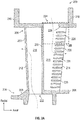
- FIG. 2A is a cross-sectional schematic illustration of airflow passages within an airfoil 200, such as a vane or blade (illustratively shown as a vane).
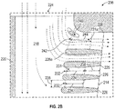
- FIG. 2B is an enlarged schematic illustration of a portion of a trailing edge of the airfoil 200 as indicated in dashed-box B shown in FIG. 2A .
- airflow passages as described herein may be applied to any type of airfoil or other component, such as blades, vanes, blade outer air seals, etc.
- the airfoil 200 has an airfoil body 202 extending radially from a first end 204 (e.g., an inner diameter or root region) to a second end 206 (e.g., an outer diameter or tip region).
- An inner platform 208 is shown at the inner diameter (e.g., first end 204), with the airfoil body 202 extending radially therefrom, and an outer platform 210 is located at the outer diameter (e.g., second end 206) of the airfoil body 202.
- the airfoil body 202 defines one or more cavities and/or flow paths therein that are configured to enable cooling of the airfoil 200.
- a first cooling cavity 216 is located proximate the leading edge 212 of the airfoil 200 and a second cooling cavity 218 is located proximate the trailing edge 214 of the airfoil 200.
- the first cooling cavity 216 is fluidly separated from the second cooling cavity 218 by a rib 220.
- the rib 220 extends from the inner platform 208 to the outer platform 210.
- the rib 220 may only extend part way between the first end 204 and the second end 206 of the airfoil 200, and thus the internal cavities thereof may be fluidly connected.
- additional ribs may be provided to enable different cooling schemes within the interior of the airfoil 200, such as forming a serpentine flow path within the airfoil 200.
- the first cooling cavity 216 is configured as a radially extending cavity within the airfoil 200 from the first end 204 to the second end 206 and the second cooling cavity 218 is configured as a radially extending cavity within the airfoil 200 from the second end 206 to the first end 204.
- the flow directions of the cooling flow into the first and second cooling cavities 216, 218 may be the opposite of that shown in FIGS. 2A-2B .
- the trailing edge 214 is configured with a plurality of pedestals 226 in the second cooling cavity 218.
- the pedestals 226, in various embodiments, are configured to supply a blockage to maintain feed pressure within the airfoil 200 (and particularly within the second cooling cavity 218), to enable a backflow margin for cooling holes within the airfoil body 202, to enable heat transfer augmentation on par with a refractory metal core of much smaller section thickness, and/or to enable clocking of the pedestals 226 as will be appreciated by those of skill in the art, to provide an even distribution of flow between stages of pedestals and out the trailing edge 214 of the airfoil 200, which may mitigate loss of stage efficiency from an increase in flow as compared to a refractory metal core airfoil.
- FIGS. 2A-2B Although shown with a single set/column/row of pedestals 226, those of skill in the art will appreciate that multiple sets/columns/rows of pedestals and/or other flow augmentation structures/features can be used within an airfoil, and thus the illustration of FIGS. 2A-2B is merely provided for illustrative and explanatory purposes and is not intended to be limiting.
- FIG. 2B a schematic illustration of a portion of a cooling airflow as it passes through the second cooling cavity 218 at the second end 206 of the airfoil 200 is shown.
- cooling air enters through the second feed supply 224 and flows into and through the second cooling cavity 218.
- a portion of the cooling airflow will turn immediately upon entering the second cooling cavity 218 and exit proximate an end wall 228 of the airfoil 200.
- the end wall 228 is a portion of the airfoil body 202 that is proximate, adjacent, and/or contacting the second platform 210, as shown in FIG. 2A .
- elongated pedestal(s) refers to any pedestal or other similar structure that has an elongated length and extends circumferentially from a pressure side to a suction side, and can include racetrack, teardrop, oval, conical, tapered, or other geometric/shape pedestal. That is, the term “elongated pedestal” is not to be limiting with respect to specific geometry, but rather refers to pedestals with shapes or geometries that adhere to the provided herein.
- the meter section 234 is defined between parallel walls or sides of the adjacent elongated pedestals 226, as shown. That is, the trailing edge slots 231 have uniform widths 236 along the meter section 234 defined by adjacent elongated pedestals 226.
- Each of the trailing edge cooling flow slots 231 further includes a tapering diffuser section 238 formed aft of the meter section 234 of a given trailing edge cooling flow slot 231.
- the tapering diffuser section 238 expands outward from the meter section 234 to the trailing edge 214. As such, the trailing edge slots 231 widen in the streamwise direction of cooling flow toward the trailing edge 214.
- the uniform width 236 of the meter sections 234 of the trailing edge cooling flow slots 231 may have a length (i.e., streamwise length) based on the hydraulic diameter, typically greater than one and a half times the hydraulic diameter (1.5 D H ).
- the incorporation and utilization of a flow development length along the metering section 234, within the trailing edge cooling flow slot(s) 231, enables the cooling flow structure to be more stable and uniformly aligned, thereby improving the convective and film cooling characteristics by reducing and/or eliminating the local vortices within the cooling flow, which inherently induce more turbulent mixing and entrainment of hot gas.
- an end slot 231a that is defined between an end (i.e., first and/or last) elongated pedestal 226a and the curved end wall 228 may not have the well-defined flow characteristics that exist in the other trailing edge slots 231. That is, flow near the end (i.e., first and/or last) elongated pedestal 226a may separate from the curved end wall 228 and generate local flow vortices 240 (e.g., flow recirculation) as the cooling airflow enters an inlet 242 of the end slot 231a located between the end (i.e., first and/or last) elongated pedestal 226a and the curved end wall 228.
- local flow vortices 240 e.g., flow recirculation
- the local flow vortices and flow separation 240 are generated because the inlet 242 of the end slot 231a between the end (i.e., first and/or last) elongated pedestal 226a and the curved end wall 228 is larger in area than the typical meter section 234 and the end slot 231a tapers (non-uniform width section 244) due to the contour of the end wall 228, as shown.
- the trailing edge pedestals 226 (and end pedestal 226a) are teardrop-shaped and have tapering sides allowing for expansion of the cooling flow in order to increase the film coverage and improve film cooling characteristics of the cooling flow between adjacent elongated pedestals 226 within the trailing edge slots 231.
- FIGS. 2A-2B Although illustrated in FIGS. 2A-2B with the curved end wall 228 located at a the second end 206 of the airfoil 200, those of skill in the art will appreciate that similar curved end walls may be implemented at the first end 204 or elsewhere within the airfoil. Thus, the illustrations of FIGS. 2A-2B are merely provided for illustrative and explanatory purposes and are not intended to be limiting.
- the shape and orientation of the elongated pedestals is selected to improve flow as it exits through the trailing edge slot of the airfoil.
- these optimized and oriented elongated pedestals may still have flow inefficiencies and/or losses due to the turning of cooling flow required.
- FIG. 3 is a cross-sectional schematic illustration of a cooling cavity 318 within an airfoil 300 (illustratively shown as a blade). Similar to that described above, an airfoil body extends radially from a first end 304 (e.g., an inner diameter or root region) to a second end (e.g., an outer diameter or tip region). As shown, the airfoil body defines the cooling cavity 318 (e.g., a trailing edge cooling cavity) to enable cooling of the airfoil 300. The cooling cavity 318 is located proximate a trailing edge 314 of the airfoil 300.
- a first end 304 e.g., an inner diameter or root region
- a second end e.g., an outer diameter or tip region
- the airfoil body defines the cooling cavity 318 (e.g., a trailing edge cooling cavity) to enable cooling of the airfoil 300.
- the cooling cavity 318 is located proximate a trailing edge 3
- a rib 320 separates various cavities of the airfoil 300, such as described above.
- the cooling cavity 318 is fed a cooling flow 346 at the first end 304 of the airfoil 300.
- the cooling flow 346 flows radially upward/outward into and through the cooling cavity 318 from a feed supply 322, as will be appreciated by those of skill in the art. That is, the cooling flow 346 flows in a feed direction D f , as shown.
- Cooling air enters the cooling cavity 318 through the feed supply 322 and flows radially outward from the first end 304 toward a second end of the airfoil in the feed direction D f .
- the trailing edge 314 is configured with a plurality of elongated pedestals 326 similar to that described above.
- Each elongated pedestal 326 has an upstream side 348 and a downstream side 350.
- the cooling flow 346 flows in the feed direction D f and will turn to flow between the elongated pedestals 326 in a bleed direction D b .
- the cooling flow 346 will turn at a bleed angle ⁇ of about 90° when entering the trailing edge slots 331 defined between adjacent elongated pedestals 326.
- the bleed angle ⁇ is the angle of change in direction of the cooling flow 346 as it turns from the feed direction D f to the bleed direction D b .
- the upstream side 348 and the downstream side 350 of the elongated pedestals 326 is based on the feed direction D f , as shown.
- the pressure feeding the trailing edge slots 331 of the airfoil is closer to static pressure than total pressure. Further, because the cooling flow 346 will turn at the bleed angle ⁇ of about 90° when entering the trailing edge slots 331, a flow separation will result off the downstream side 350 generating local flow vorticities 340, as illustratively shown.
- the local flow vorticities 340 create regions of local flow separation and recirculation.
- FIG. 4 is a cross-sectional schematic illustration of a cooling cavity 418 within an airfoil 400 (illustratively shown as a blade). Similar to that described above, an airfoil body extends radially from a first end 404 (e.g., an inner diameter or root region) to a second end (e.g., an outer diameter or tip region). As shown, the airfoil body defines the cooling cavity 418 (e.g., a trailing edge cooling cavity) to enable cooling of the airfoil 400. The cooling cavity 418 is located proximate a trailing edge 414 of the airfoil 400. The cooling cavity 418 is fed a cooling flow 446 at the first end 404 of the airfoil 400. The cooling flow 446 flows radially upward/outward into and through the cooling cavity 418 in a feed direction D f , as shown.
- the cooling flow 446 flows radially upward/outward into and through the cooling cavity 418 in a feed direction D f , as shown
- the trailing edge slots 431 are defined by a plurality of elongated pedestals 426 similar to that described above. Each elongated pedestal 426 has an upstream side 448 and a downstream side 450. Further, similar to the elongated pedestals described above, the elongated pedestals 426 have a meter section 434 and a diffuser section 438.
- the meter section 434 of the elongated pedestals 426 are relatively oriented to define parallel walls that define a constant width (e.g., constant flow area) trailing edge slot 431.
- the diffuser sections 438 define tapering walls that expand the width of the trailing edge slots 431 as the trailing edge slots 431 approach the trailing edge 414 of the airfoil 400.
- the cooling flow 446 flows in the feed direction D f and will turn to flow between the elongated pedestals 426 in a bleed direction D b .
- the cooling flow 446 will turn at a bleed angle ⁇ that is less than 90° when entering the trailing edge slots 431 defined between adjacent elongated pedestals 426.
- the bleed angle ⁇ is the relative angle of change in direction of flow of the cooling flow 446 as it turns from the feed direction D f to the bleed direction D b .
- the upstream side 448 and the downstream side 450 of the elongated pedestals 426 is based on the feed direction D f , as shown, and with the less than 90° bleed angle ⁇ , the local flow vorticities and subsequent flow separation 240, 340 along the downstream side 450 shown in FIGS. 2-3 may be reduced and/or eliminated.
- the bleed angle ⁇ may be between 15° and 70° with respect to the feed direction D f and the cooling flow 446.
- the bleed angle ⁇ is defined by the angle of the trailing edge slots 431 defined between angled elongated pedestals 426.
- the slanted elongated pedestals 426 are oriented at the bleed angle ⁇ such that the meter sections 434 of the angled elongated pedestals 426 incorporate parallel metering wall features that are oriented in a direction parallel to the bleed angle ⁇ .
- the diffuser sections 438 extend toward the trailing edge 414 from the ends of the metered sections 434.
- Airfoils of the present disclosure include a plurality of angled elongated pedestals 426 with each elongated pedestal being substantially oriented similar to either adjacent angled elongated pedestal, thereby creating parallel meter sections 434 that are present through the plurality of angled elongated pedestal features.
- the meter sections 434 have uniform width and have a length (i.e., streamwise length) based on the hydraulic diameter.
- the streamwise length of the meter section 434 may be greater than one and a half times the hydraulic diameter (1.5 D H ).
- the streamwise distance of the meter section 434 provides a development length necessary to "condition” the cooling flow within the trailing edge cooling flow slots 431.
- the ability to "condition” the cooling flow ensure a more stable and uniformly distributed flow structure is achieved within the cooling flow slots 431, thereby maximizing the local convective heat transfer, film cooling, and thermal cooling effectiveness characteristics immediately adjacent to the airfoil trailing edge.
- the meter sections 434, and the walls or portions of the slanted elongated pedestals 426 are parallel.
- the angle in which flow is bled off from the cooling cavity 418 into the trailing edge slots 431 is less than 90°, the pressure feeding the trailing edge slots 431 is closer to total pressure than static pressure. Further, because the trailing edge slots 431 are angled at the bleed angle ⁇ in the same direction that the rotational centrifugal effect causes cooling flow to be urged radially outward, the flow separation described above may be significantly minimized or eliminated.
- the local flow vorticities and region of flow separation described above that typically occurs along the elongated pedestals at the entrance to the trailing edge slots 431 due to the high rate of flow turning associated with the bleed angle ⁇ that is more consistent with 90°, may be reduced or eliminated due to the decreased relative turning of the cooling airflow flow 446 associated with the incorporation of angled elongated pedestals of the present disclosure.
- the first airfoil 500a includes a plurality of elongated pedestals 526a arranged with parallel orientation and angled at substantially 90° to a feed direction (e.g., as shown and described with respect to FIG. 3 ).
- the second airfoil 500b includes a plurality of angled elongated pedestals 526b arranged with parallel orientation and angled at a bleed direction with respect to a feed direction that is less than 90° (e.g., as shown and described with respect to FIG. 4 ).
- the elongated pedestals 526a of the first airfoil 500a have a first axial pedestal length L a .
- the angled elongated pedestals 526b of the second airfoil 500b have a second axial pedestal length L b . Due to the angle of orientation of the angled elongated pedestals 526b of the second airfoil 500b, the second axial pedestal length L b may be less than the first axial pedestal length L a . As such, the angled pedestals 526b occupy less physical space within the respective second airfoil 500b in the axial direction (e.g., left to right on the page of FIG. 5 ).
- This reduced axial dimension enables a larger cooling cavity at the trailing edge of the airfoil. That is, for the same trailing edge slot length, the axial length may be reduced. This provides for more room in the cooling cavity and shifts the high heat transfer found in the meter sections to be closer to the trailing edge.
- the relative reduction of the conduction length associated with angled elongated pedestals enables the highest internal convective heat transfer located within the metering section of the trailing edge slot to be located in more immediate proximity to the airfoil trailing edge location, thereby increasing the local thermal cooling effectiveness, improving local airfoil trailing edge durability, oxidation, creep, and thermal mechanical failure (TMF) life capability.
- FIG. 6 an alternative configuration of an airfoil 600 in accordance with an embodiment of the present disclosure is shown.
- the airfoil 600 is similar to that described above, and thus similar features may not be described again.
- the airfoil 600 includes a plurality of angled elongated pedestals 626 arranged along a trailing edge 614 of the airfoil 600.
- located upstream of the angled elongated pedestals 626, within a cooling cavity 618, may be one or more upstream heat transfer augmentation features 656.
- the upstream heat transfer augmentation features 656 may be pedestals, trip strips, pin fins, hemispherical bumps, protrusions, dimples, or other structure that may increase thermal transfer at the trailing edge of the airfoil 600. In some embodiments, the upstream heat transfer augmentation features 656 may aid in turning a cooling flow toward the angled elongated pedestals 626.
- the airfoil 700 includes a plurality of angled elongated pedestals 726 arranged along a trailing edge 714 of the airfoil 700. As shown, located upstream of the angled elongated pedestals 726, within a cooling cavity 718, may be one or more upstream heat transfer augmentation features 756.
- the upstream heat transfer augmentation features 756 of this embodiment are arranged as an impingement rib structure that may increase thermal transfer at the trailing edge of the airfoil 700 and aid in turning a cooling flow toward the angled elongated pedestals 726.
- the airfoil 800 includes a plurality of angled elongated pedestals 826 arranged along a trailing edge 814 of the airfoil 800.
- each angled elongated pedestal 826 has a respective upstream side 848 and a respective downstream side 850, which are angled with respect to a feed direction D f .
- the angled pedestals 826 are oriented in a bleed direction D b at a bleed angle ⁇ .
- the angled pedestals 826 have meter sections 834 and diffuser sections 838.
- the meter sections 834 are defined by parallel walls of the angled elongated pedestals 826.
- the diffuser sections 838 of some embodiments of the present disclosure may have differing diffusion angles (i.e., the change in wall angle after the meter section 834 ends).
- a trailing edge slot 831 may have a diffuser section 838 defined by a first diffusion angle ⁇ and a second diffusion angle ⁇ .
- the first diffusion angle ⁇ is along the upstream side 848 of a given angled elongated pedestal 826 and defines the downstream side of the trailing edge slot 831.
- the second diffusion angle ⁇ is along the downstream side 850 of the adjacent and opposing angled elongated pedestal 826 and defines the upstream side of the same trailing edge slot 831.
- the first diffusion angle ⁇ and the second diffusion angle ⁇ may be different, producing a non-axisymmetric tapered geometry feature.
- the first diffusion angle ⁇ may be an angle between 0° and about 20° and the second diffusion angle ⁇ may be an angle between 0° and about 7°.
- centrifugal forces allow for the diffusion angles to be larger on the upstream side 848 as compared to the downstream side 850 of the angled elongated pedestals 826.
- larger radial slot diffusion angles are acceptable due to rotational inertial forces which inherently "push" the flow toward the radially outboard or downstream side of the trailing edge slot 831.
- the radially inboard or upstream side of the trailing edge slot 831 requires “smaller” diffusion angles in order to mitigate the potential for cooling flow separation due to the rotational inertial forces, which "pulls" the flow away from the upstream side of the trailing edge slot 831, generating local flow vortices that can entrain hot freestream gas reducing the local thermal performance of the airfoil trailing edge.
- FIG. 9 a schematic illustration of an airfoil 900 having angled elongated pedestals 926, in accordance with an embodiment of the present disclosure, is shown.
- the airfoil 900 is similar to that described above, and thus similar features may not be described again.
- the airfoil 900 includes a plurality of angled elongated pedestals 926 arranged along a trailing edge 914 of the airfoil 900.
- the angled elongated pedestals 926 have constant length. That is, the total length of each angled pedestal 926 is the same.
- the angled elongated pedestals 926 arranged along a bowed trailing edge 914 of the airfoil 900.
- FIG. 10 a schematic illustration of an airfoil 1000 having angled elongated pedestals 1026, in accordance with an embodiment of the present disclosure, is shown.
- the airfoil 1000 is similar to that described above, and thus similar features may not be described again.
- the airfoil 1000 includes a plurality of angled elongated pedestals 1026 arranged along a bowed trailing edge 1014 of the airfoil 1000.
- the angled elongated pedestals 1026 have variable length. That is, the total length of each angled elongated pedestal 1026 may be different, or in sets of different length angled elongated pedestals 1026. The different lengths may be employed to achieve desired cooling and/or cooling flow characteristics within the airfoil 1000.
- the angled elongated pedestals are all arranged to be parallel along the length of the trailing edge. However, in some embodiments, not all of the angled elongated pedestals need be angled at the same angle or even in the same direction.
- a trailing edge cooling cavity may be fed cooling air from both the inner and outer diameters (e.g., in a vane).
- a serpentine flow can be employed to supply cooling air proximate the tip, and thus radially inward flowing, while a separate supply of cooling air can be provided from the root region, thus allowing for contra-sourced cooling flows in a blade.
- FIG. 11 a schematic illustration of an airfoil 1100 in accordance with an embodiment of the present disclosure is shown.
- the airfoil 1100 is similar to that described above, and thus similar features may not be described again.
- the airfoil 1100 includes two sets of angled elongated pedestals, a first set 1126a and a second set 1126b, arranged along a trailing edge 1114 of the airfoil 1100.
- the airfoil 1100 has a first trailing edge cooling cavity 1118a and a second trailing edge cooling cavity 1118b.
- first trailing edge cooling cavity 1118a is fed cooling air at a first end 1104 (e.g., inner diameter) and the second trailing edge cooling cavity 1118b is fed cooling air at a second end 1106 (e.g., outer diameter).
- the first trailing edge cooling cavity 1118a is separated from the second trailing edge cooling cavity 1118b by a dividing rib 1158.
- Each of the angled elongated pedestals of the sets 1126a, 1126b are angled with respect to the cooling flow that is fed into the respective cavities, as illustratively shown.
- the dividing rib 1158 extends in an axial direction (e.g., aftward) from a rib 1120 to the trailing edge 1114 to separate the first trailing edge cooling cavity 1118a and the second trailing edge cooling cavity 1118b.
- FIG. 12 a schematic illustration of an airfoil 1200 in accordance with an embodiment of the present disclosure is shown.
- the airfoil 1200 is similar to that described above, and thus similar features may not be described again.
- the airfoil 1200 includes two sets of angled elongated pedestals, a first set 1226a and a second set 1226b, arranged along a trailing edge 1214 of the airfoil 1200.
- the airfoil 1200 has a first trailing edge cooling cavity 1218a and a second trailing edge cooling cavity 1218b.
- first trailing edge cooling cavity 1218a is fed cooling air at a first end 1204 (e.g., inner diameter) and the second trailing edge cooling cavity 1218b is fed cooling air at a second end 1206 (e.g., outer diameter).
- the first trailing edge cooling cavity 1218a is separated from the second trailing edge cooling cavity 1218b by a dividing rib 1258.
- Each of the angled elongated pedestals of the sets 1226a, 1226b are angled with respect to the cooling flow that is fed into the respective cavities, as illustratively shown.
- the dividing rib 1258 extends in an axial direction (e.g., aftward) from a rib 1220 to the trailing edge 1214 to separate the first trailing edge cooling cavity 1218a and the second trailing edge cooling cavity 1218b.
- the dividing rib 1258 includes a rib flow control feature 1260 located where the dividing rib 1258 intersects with the trailing edge 1214.
- the rib flow control feature 1260 is an optional feature that may maintain the meter section of the last trailing edge slot in the trailing edge cooling cavities 1218a, 1218b.
- the rib flow control feature 1260 may be hollow or solid and may include impingement holes, film cooling holes, etc. as will be appreciated by those of skill in the art.
- FIG. 13 a schematic illustration of an airfoil 1300 in accordance with an embodiment of the present disclosure is shown.
- the airfoil 1300 is similar to that described above, and thus similar features may not be described again.
- the airfoil 1300 includes two sets of angled elongated pedestals, a first set 1326a and a second set 1326b, arranged along a trailing edge 1314 of the airfoil 1300.
- the airfoil 1300 has a first trailing edge cooling cavity 1318a and a second trailing edge cooling cavity 1318b.
- first trailing edge cooling cavity 1318a is fed cooling air at a first end 1304 (e.g., inner diameter) and the second trailing edge cooling cavity 1318b is fed cooling air at a second end 1306 (e.g., outer diameter).
- the first trailing edge cooling cavity 1318a is separated from the second trailing edge cooling cavity 1318b by a dividing rib 1358.
- Each of the angled elongated pedestals of the sets 1326a, 1326b are angled with respect to the cooling flow that is fed into the respective cavities, as illustratively shown.
- the dividing rib 1358 extends in an axial direction (e.g., aftward) from a rib 1320 toward the trailing edge 1314 to separate the first trailing edge cooling cavity 1318a and the second trailing edge cooling cavity 1318b.
- the dividing rib does not extend the complete length to the trailing edge 1314, but rather may end short of the trailing edge 1314.
- a merging region 1362 may be defined as a region at an end of the dividing rib 1358 and between end elongated pedestals of the sets 1326a, 1326b of angled elongated pedestals.
- the dividing rib located about mid span in the radial direction, such position is not to be limiting.
- the dividing rib may be arranged at any desired radial position within the respective airfoil.
- the metering length (i.e., length of the meter section) between any two adjacent elongated pedestals features will have a minimum metering length (e.g., 1.5 D H ).
- the total metering length for one elongated pedestal to any adjacent elongated pedestal may be different because the relative orientation angle of the elongated pedestal features may differ.
- the elongated pedestal feature length may change as function of radial location along the airfoil trailing edge.
- the amount of "overlap" between adjacent metering sections must be maintained at a minimum of one and a half times the hydraulic diameter (1.5 D H ).
- the overall length of the elongated pedestal feature and the meter length requirements for any two adjacent elongated pedestal features may be dictated by the shape of the airfoil trailing edge.
- the shape of the airfoil trailing edge may be, without limitation, linear, tapered, concave curvature/bow, convex curvature/bow as a function of the airfoil true chord.
- any two adjacent angled elongated pedestals may also impact the relative taper angles to be unique for each upstream and downstream side of the of any two adjacent elongated pedestal features. Additionally the length of the elongated pedestal geometry may also be dictated by cooling air temperature heat pick considerations as well as internal convective metering slot heat transfer requirements in order to effectively cool the local airfoil trailing edge region.
- embodiment described herein provide for improved cooling flow at trailing edges of airfoils.
- the improved cooling is achieved through the inclusion of a plurality of angled elongated pedestals that are parallel to each other and defining meter sections between adjacent angled elongated pedestals.
- the angled elongated pedestals reduce the angle that a cooling flow has to make to enter a trailing edge slot defined between adjacent angled elongated pedestals. Accordingly, flow separation may be minimized or eliminated, resulting in lower pressure loss and better convective cooling flow characteristics.
- the angled elongated pedestal arrangements described herein may eliminate the need for additional upstream flow conditioning features, such as crossover holes and pedestals.
- additional real estate may be freed up for the radially extending cooling cavity (e.g., feed passage) at the trailing edge of the airfoil.
- the angling of the trailing edge slots reduces the axial length of the slots while maintaining the same meter section length, giving even more real estate for the radial feed passage and bringing a high heat transfer coefficient found in the slot meter section closer to the trailing edge.
Landscapes
- Engineering & Computer Science (AREA)
- Mechanical Engineering (AREA)
- General Engineering & Computer Science (AREA)
- Turbine Rotor Nozzle Sealing (AREA)
Abstract
Description
- The subject matter disclosed herein generally relates to airflow in components of gas turbine engines and, more particularly, to pedestals and slots in a trailing edge cavity of an airfoil in components of gas turbine engines.
- Airfoils, and particularly airfoils of gas turbine engines, may include internal flow passages to enable cooling of the airfoils. The supply of the cooling air through cavities of the airfoils may be carefully designed so as to provide an efficient cooling configuration. However, various structures and/or features of the airfoils may impact cooling schemes, thus reducing the efficiency and/or effectiveness of a cooling scheme.
- According to some embodiments, airfoils for gas turbine engines are provided. The airfoils include an airfoil body having a leading edge and a trailing edge and extending in a radial direction, a cooling cavity defined within the airfoil body at the trailing edge, and a plurality of angled pedestals arranged along the trailing edge, wherein the plurality of angled pedestals define a plurality of angled trailing edge slots therebetween. Adjacent angled pedestals of the plurality of angled pedestals define a meter section of a respective angled trailing edge slot and a diffuser section of the respective angled trailing edge slot, wherein the meter section is defined by parallel sides of the adjacent angled pedestals, and wherein the parallel sides of the adjacent angled pedestals are oriented at a bleed direction that is less than 90° with respect to a feed direction through the cooling cavity.
- Further embodiments of the airfoils may include that the bleed direction is between 40° and 70° with respect to the feed direction.
- Further embodiments of the airfoils may include that the meter section has a length that is a minimum of one and a half times a hydraulic diameter.
- Further embodiments of the airfoils may include an upstream heat transfer augmentation feature arranged within the cooling cavity upstream relative to the plurality of angled pedestals in a flow direction through the cooling cavity.
- Further embodiments of the airfoils may include that the upstream heat transfer augmentation feature comprises a plurality of pedestals.
- Further embodiments of the airfoils may include that the upstream heat transfer augmentation feature comprises an impingement rib.
- Further embodiments of the airfoils may include that the diffuser section is defined between tapering walls of adjacent elongated pedestals of the plurality of angled pedestals, the diffuser section extending from the meter section to the trailing edge, wherein a downstream side defining the diffusion section has an angle β and an upstream side defining the diffusion section has an angle γ.
- Further embodiments of the airfoils may include that the angle β is greater than the angle γ.
- Further embodiments of the airfoils may include that the angle β is between 0° and 20°.
- Further embodiments of the airfoils may include that the angle γ is between 0° and 7°.
- Further embodiments of the airfoils may include a dividing rib separating the cooling cavity into a first cooling cavity and a second cooling cavity, wherein the dividing rib extends in an axial direction from a radially extending rib of the airfoil through the cooling cavity toward the trailing edge, wherein a first set of angled pedestals of the plurality of pedestals is located within the first cooling cavity.
- Further embodiments of the airfoils may include that the second cooling cavity includes a second set of angled pedestals.
- Further embodiments of the airfoils may include that the dividing rib extends a full distance from the radially extending rib to the trailing edge.
- Further embodiments of the airfoils may include that the first cooling cavity is fed cooling air from a first end of the airfoil and the second cooling cavity is fed cooling air from a second end of the airfoil.
- Further embodiments of the airfoils may include a rib flow control feature located at a trailing edge end of the dividing rib.
- Further embodiments of the airfoils may include that the rib flow control feature is hollow.
- Further embodiments of the airfoils may include that the trailing edge is a bowed trailing edge.
- Further embodiments of the airfoils may include that each angled pedestal of the plurality of angled pedestals is the same length.
- Further embodiments of the airfoils may include that the angled pedestals of the plurality of angled pedestals having varying lengths.
- Further embodiments of the airfoils may include that each angled pedestal of the plurality of angled pedestals is teardrop-shaped.
- Further embodiments of the airfoils may include that the plurality of angled pedestals are arranged parallel to each other.
- The foregoing features and elements may be executed or utilized in various combinations without exclusivity, unless expressly indicated otherwise. These features and elements as well as the operation thereof will become more apparent in light of the following description and the accompanying drawings. It should be understood, however, that the following description and drawings are intended to be illustrative and explanatory in nature and non-limiting.
- The subject matter is particularly pointed out and distinctly claimed at the conclusion of the specification. The foregoing and other features, and advantages of the present disclosure are apparent from the following detailed description taken in conjunction with the accompanying drawings in which:
-
FIG. 1A is a schematic cross-sectional illustration of a gas turbine engine that may employ various embodiments disclosed herein; -
FIG. 1B is a schematic illustration of a turbine that may employ various embodiments disclosed herein; -
FIG. 2A is a schematic illustration of an airfoil that may employ embodiments of the present disclosure; -
FIG. 2B is an enlarged schematic illustration of a portion of a trailing edge of the airfoil as indicated in dashed-box B shown inFIG. 2A ; -
FIG. 3 is a schematic illustration of a portion of a trailing edge of an airfoil; -
FIG. 4 is a schematic illustration of a portion of a trailing edge of an airfoil in accordance with an embodiment of the present disclosure; -
FIG. 5 is a schematic comparison between prior pedestal configurations and a pedestal configuration in accordance with an embodiment of the present disclosure; -
FIG. 6 is a schematic illustration of a portion of a trailing edge of an airfoil in accordance with an embodiment of the present disclosure; -
FIG. 7 is a schematic illustration of a portion of a trailing edge of an airfoil in accordance with an embodiment of the present disclosure; -
FIG. 8 is a schematic illustration of a portion of a trailing edge of an airfoil in accordance with an embodiment of the present disclosure; -
FIG. 9 is a schematic illustration of an airfoil in accordance with an embodiment of the present disclosure; -
FIG. 10 is a schematic illustration of an airfoil in accordance with an embodiment of the present disclosure; -
FIG. 11 is a schematic illustration of an airfoil in accordance with an embodiment of the present disclosure; -
FIG. 12 is a schematic illustration of an airfoil in accordance with an embodiment of the present disclosure; and -
FIG. 13 is a schematic illustration of an airfoil in accordance with an embodiment of the present disclosure; -
FIG. 1A schematically illustrates agas turbine engine 20. The exemplarygas turbine engine 20 is a two-spool turbofan engine that generally incorporates afan section 22, acompressor section 24, acombustor section 26, and aturbine section 28. Thefan section 22 drives air along a bypass flow path B, while thecompressor section 24 drives air along a core flow path C for compression and communication into thecombustor section 26. Hot combustion gases generated in thecombustor section 26 are expanded through theturbine section 28. Although depicted as a turbofan gas turbine engine in the disclosed non-limiting embodiment, it should be understood that the concepts described herein are not limited to turbofan engines and these teachings could extend to other types of engines. - The
gas turbine engine 20 generally includes alow speed spool 30 and ahigh speed spool 32 mounted for rotation about an engine centerline longitudinal axis A. Thelow speed spool 30 and thehigh speed spool 32 may be mounted relative to an enginestatic structure 33 viaseveral bearing systems 31. It should be understood thatother bearing systems 31 may alternatively or additionally be provided. - The
low speed spool 30 generally includes an inner shaft 34 that interconnects afan 36, alow pressure compressor 38 and alow pressure turbine 39. The inner shaft 34 can be connected to thefan 36 through a gearedarchitecture 45 to drive thefan 36 at a lower speed than thelow speed spool 30. Thehigh speed spool 32 includes anouter shaft 35 that interconnects ahigh pressure compressor 37 and ahigh pressure turbine 40. In this embodiment, the inner shaft 34 and theouter shaft 35 are supported at various axial locations by bearingsystems 31 positioned within the enginestatic structure 33. - A
combustor 42 is arranged between thehigh pressure compressor 37 and thehigh pressure turbine 40. Amid-turbine frame 44 may be arranged generally between thehigh pressure turbine 40 and thelow pressure turbine 39. Themid-turbine frame 44 can support one ormore bearing systems 31 of theturbine section 28. Themid-turbine frame 44 may include one or more airfoils 46 that extend within the core flow path C. - The inner shaft 34 and the
outer shaft 35 are concentric and rotate via the bearingsystems 31 about the engine centerline longitudinal axis A, which is co-linear with their longitudinal axes. The core airflow is compressed by thelow pressure compressor 38 and thehigh pressure compressor 37, is mixed with fuel and burned in thecombustor 42, and is then expanded over thehigh pressure turbine 40 and thelow pressure turbine 39. Thehigh pressure turbine 40 and thelow pressure turbine 39 rotationally drive the respectivehigh speed spool 32 and thelow speed spool 30 in response to the expansion. - The pressure ratio of the
low pressure turbine 39 can be pressure measured prior to the inlet of thelow pressure turbine 39 as related to the pressure at the outlet of thelow pressure turbine 39 and prior to an exhaust nozzle of thegas turbine engine 20. In one non-limiting embodiment, the bypass ratio of thegas turbine engine 20 is greater than about ten (10:1), the fan diameter is significantly larger than that of thelow pressure compressor 38, and thelow pressure turbine 39 has a pressure ratio that is greater than about five (5:1). It should be understood, however, that the above parameters are only examples of one embodiment of a geared architecture engine and that the present disclosure is applicable to other gas turbine engines, including direct drive turbofans. - In this embodiment of the example
gas turbine engine 20, a significant amount of thrust is provided by the bypass flow path B due to the high bypass ratio. Thefan section 22 of thegas turbine engine 20 is designed for a particular flight condition-typically cruise at about 0.8 Mach and about 35,000 feet (10,866 m). This flight condition, with thegas turbine engine 20 at its best fuel consumption, is also known as bucket cruise Thrust Specific Fuel Consumption (TSFC). TSFC is an industry standard parameter of fuel consumption per unit of thrust. - Fan Pressure Ratio is the pressure ratio across a blade of the
fan section 22 without the use of a Fan Exit Guide Vane system. The low Fan Pressure Ratio according to one non-limiting embodiment of the examplegas turbine engine 20 is less than 1.45. Low Corrected Fan Tip Speed is the actual fan tip speed divided by an industry standard temperature correction of [(Tram ° R)/(518.7° R)]0.5, where T represents the ambient temperature in degrees Rankine. The Low Corrected Fan Tip Speed according to one non-limiting embodiment of the examplegas turbine engine 20 is less than about 1150 fps (351 m/s). - Each of the
compressor section 24 and theturbine section 28 may include alternating rows of rotor assemblies and vane assemblies (shown schematically) that carry airfoils that extend into the core flow path C. For example, the rotor assemblies can carry a plurality ofrotating blades 25, while each vane assembly can carry a plurality ofvanes 27 that extend into the core flow path C. Theblades 25 of the rotor assemblies create or extract energy (in the form of pressure) from the core airflow that is communicated through thegas turbine engine 20 along the core flow path C. Thevanes 27 of the vane assemblies direct the core airflow to theblades 25 to either add or extract energy. - Various components of a
gas turbine engine 20, including but not limited to the airfoils of theblades 25 and thevanes 27 of thecompressor section 24 and theturbine section 28, may be subjected to repetitive thermal cycling under widely ranging temperatures and pressures. The hardware of theturbine section 28 is particularly subjected to relatively extreme operating conditions. Therefore, some components may require internal cooling circuits for cooling the parts during engine operation. Example cooling circuits that include features such as airflow bleed ports are discussed below. -
FIG. 1B is a schematic view of a turbine section that may employ various embodiments disclosed herein.Turbine 100 includes a plurality of airfoils, including, for example, one ormore blades 101 andvanes 102. Theairfoils inner diameter 106 to anouter diameter 108, or vice-versa. The airfoil cavities may be separated by partitions within theairfoils inner diameter 106 or theouter diameter 108 of theairfoil airfoil airfoil respective airfoil blades 101 and thevanes 102 may includeplatforms 110 located proximal to the inner diameter thereof. Located below theplatforms 110 may be airflow ports and/or bleed orifices that enable air to bleed from the internal cavities of theairfoils platform 110. - Although an aero or aircraft engine application is shown and described above, those of skill in the art will appreciate that airfoil configurations as described herein may be applied to industrial applications and/or industrial gas turbine engines, land based or otherwise.
- Turning now to
FIGS. 2A and2B , views of an airfoil interior structure are shown.FIG. 2A is a cross-sectional schematic illustration of airflow passages within anairfoil 200, such as a vane or blade (illustratively shown as a vane).FIG. 2B is an enlarged schematic illustration of a portion of a trailing edge of theairfoil 200 as indicated in dashed-box B shown inFIG. 2A . Those of skill in the art will appreciate that airflow passages as described herein may be applied to any type of airfoil or other component, such as blades, vanes, blade outer air seals, etc. - As shown, the
airfoil 200 has anairfoil body 202 extending radially from a first end 204 (e.g., an inner diameter or root region) to a second end 206 (e.g., an outer diameter or tip region). Aninner platform 208 is shown at the inner diameter (e.g., first end 204), with theairfoil body 202 extending radially therefrom, and anouter platform 210 is located at the outer diameter (e.g., second end 206) of theairfoil body 202. As shown, theairfoil body 202 defines one or more cavities and/or flow paths therein that are configured to enable cooling of theairfoil 200. - A
first cooling cavity 216 is located proximate theleading edge 212 of theairfoil 200 and asecond cooling cavity 218 is located proximate the trailingedge 214 of theairfoil 200. Thefirst cooling cavity 216 is fluidly separated from thesecond cooling cavity 218 by arib 220. In the embodiment ofFIG. 2A , therib 220 extends from theinner platform 208 to theouter platform 210. However, in other embodiments, therib 220 may only extend part way between thefirst end 204 and thesecond end 206 of theairfoil 200, and thus the internal cavities thereof may be fluidly connected. Further, in some embodiments, additional ribs may be provided to enable different cooling schemes within the interior of theairfoil 200, such as forming a serpentine flow path within theairfoil 200. As shown, thefirst cooling cavity 216 is configured as a radially extending cavity within theairfoil 200 from thefirst end 204 to thesecond end 206 and thesecond cooling cavity 218 is configured as a radially extending cavity within theairfoil 200 from thesecond end 206 to thefirst end 204. - Cooling air enters the
first cooling cavity 216 through afirst feed supply 222 that is formed in thefirst platform 208. The air will then flow from thefirst end 204 toward thesecond end 206 of theairfoil body 202. As the air flows through thefirst cooling cavity 216, a portion of the air may be expunged or bled through one or more apertures within the surfaces of theairfoil body 202 and thus be ejected into a gaspath. Cooling air enters thesecond cooling cavity 218 through asecond feed supply 224 that is formed in thesecond platform 210. The air will then flow from thesecond end 206 toward thefirst end 204 of theairfoil body 202. As the air flows through thesecond cooling cavity 218, a portion of the air will exit through the trailingedge 214 of theairfoil body 202 and thus be ejected into the gaspath. In some embodiments, the flow directions of the cooling flow into the first andsecond cooling cavities FIGS. 2A-2B . - As shown in the example embodiment of
FIG. 2A , the trailingedge 214 is configured with a plurality ofpedestals 226 in thesecond cooling cavity 218. Thepedestals 226, in various embodiments, are configured to supply a blockage to maintain feed pressure within the airfoil 200 (and particularly within the second cooling cavity 218), to enable a backflow margin for cooling holes within theairfoil body 202, to enable heat transfer augmentation on par with a refractory metal core of much smaller section thickness, and/or to enable clocking of thepedestals 226 as will be appreciated by those of skill in the art, to provide an even distribution of flow between stages of pedestals and out the trailingedge 214 of theairfoil 200, which may mitigate loss of stage efficiency from an increase in flow as compared to a refractory metal core airfoil. Although shown with a single set/column/row ofpedestals 226, those of skill in the art will appreciate that multiple sets/columns/rows of pedestals and/or other flow augmentation structures/features can be used within an airfoil, and thus the illustration ofFIGS. 2A-2B is merely provided for illustrative and explanatory purposes and is not intended to be limiting. - Turning to
FIG. 2B , a schematic illustration of a portion of a cooling airflow as it passes through thesecond cooling cavity 218 at thesecond end 206 of theairfoil 200 is shown. As noted, cooling air enters through thesecond feed supply 224 and flows into and through thesecond cooling cavity 218. A portion of the cooling airflow will turn immediately upon entering thesecond cooling cavity 218 and exit proximate anend wall 228 of theairfoil 200. Theend wall 228 is a portion of theairfoil body 202 that is proximate, adjacent, and/or contacting thesecond platform 210, as shown inFIG. 2A . - As shown in
FIG. 2B , adjacentelongated pedestals 226 are spaced to define trailing edgecooling flow slots 231, and typically a uniform spacing is provided at aninlet 232 and extends along ameter section 234. As used herein, the term "elongated pedestal(s)" refers to any pedestal or other similar structure that has an elongated length and extends circumferentially from a pressure side to a suction side, and can include racetrack, teardrop, oval, conical, tapered, or other geometric/shape pedestal. That is, the term "elongated pedestal" is not to be limiting with respect to specific geometry, but rather refers to pedestals with shapes or geometries that adhere to the provided herein. - The
meter section 234 is defined between parallel walls or sides of the adjacentelongated pedestals 226, as shown. That is, the trailingedge slots 231 haveuniform widths 236 along themeter section 234 defined by adjacentelongated pedestals 226. Each of the trailing edgecooling flow slots 231 further includes a taperingdiffuser section 238 formed aft of themeter section 234 of a given trailing edgecooling flow slot 231. The taperingdiffuser section 238 expands outward from themeter section 234 to the trailingedge 214. As such, the trailingedge slots 231 widen in the streamwise direction of cooling flow toward the trailingedge 214. Theuniform width 236 of themeter sections 234 of the trailing edgecooling flow slots 231 may have a length (i.e., streamwise length) based on the hydraulic diameter, typically greater than one and a half times the hydraulic diameter (1.5 DH). The incorporation and utilization of a flow development length along themetering section 234, within the trailing edge cooling flow slot(s) 231, enables the cooling flow structure to be more stable and uniformly aligned, thereby improving the convective and film cooling characteristics by reducing and/or eliminating the local vortices within the cooling flow, which inherently induce more turbulent mixing and entrainment of hot gas. - However, as illustratively shown in
FIG. 2B , anend slot 231a that is defined between an end (i.e., first and/or last) elongatedpedestal 226a and thecurved end wall 228 may not have the well-defined flow characteristics that exist in the other trailingedge slots 231. That is, flow near the end (i.e., first and/or last) elongatedpedestal 226a may separate from thecurved end wall 228 and generate local flow vortices 240 (e.g., flow recirculation) as the cooling airflow enters aninlet 242 of theend slot 231a located between the end (i.e., first and/or last) elongatedpedestal 226a and thecurved end wall 228. The local flow vortices and flowseparation 240 are generated because theinlet 242 of theend slot 231a between the end (i.e., first and/or last) elongatedpedestal 226a and thecurved end wall 228 is larger in area than thetypical meter section 234 and theend slot 231a tapers (non-uniform width section 244) due to the contour of theend wall 228, as shown. As shown, the trailing edge pedestals 226 (andend pedestal 226a) are teardrop-shaped and have tapering sides allowing for expansion of the cooling flow in order to increase the film coverage and improve film cooling characteristics of the cooling flow between adjacentelongated pedestals 226 within the trailingedge slots 231. - Although illustrated in
FIGS. 2A-2B with thecurved end wall 228 located at a thesecond end 206 of theairfoil 200, those of skill in the art will appreciate that similar curved end walls may be implemented at thefirst end 204 or elsewhere within the airfoil. Thus, the illustrations ofFIGS. 2A-2B are merely provided for illustrative and explanatory purposes and are not intended to be limiting. - As discussed, the shape and orientation of the elongated pedestals is selected to improve flow as it exits through the trailing edge slot of the airfoil. However, these optimized and oriented elongated pedestals may still have flow inefficiencies and/or losses due to the turning of cooling flow required.
- For example, turning now to
FIG. 3 , a schematic illustration of an airfoil interior structure is shown.FIG. 3 is a cross-sectional schematic illustration of acooling cavity 318 within an airfoil 300 (illustratively shown as a blade). Similar to that described above, an airfoil body extends radially from a first end 304 (e.g., an inner diameter or root region) to a second end (e.g., an outer diameter or tip region). As shown, the airfoil body defines the cooling cavity 318 (e.g., a trailing edge cooling cavity) to enable cooling of theairfoil 300. Thecooling cavity 318 is located proximate a trailingedge 314 of theairfoil 300. Arib 320 separates various cavities of theairfoil 300, such as described above. Thecooling cavity 318 is fed acooling flow 346 at thefirst end 304 of theairfoil 300. Thecooling flow 346 flows radially upward/outward into and through thecooling cavity 318 from afeed supply 322, as will be appreciated by those of skill in the art. That is, thecooling flow 346 flows in a feed direction Df, as shown. - Cooling air enters the
cooling cavity 318 through thefeed supply 322 and flows radially outward from thefirst end 304 toward a second end of the airfoil in the feed direction Df. As the air flows through thecooling cavity 318, a portion of the air will exit through the trailingedge 314 of the airfoil and thus be ejected into the gaspath. As shown, the trailingedge 314 is configured with a plurality ofelongated pedestals 326 similar to that described above. Eachelongated pedestal 326 has anupstream side 348 and adownstream side 350. Thecooling flow 346 flows in the feed direction Df and will turn to flow between theelongated pedestals 326 in a bleed direction Db. In this configuration, as shown, thecooling flow 346 will turn at a bleed angle α of about 90° when entering the trailingedge slots 331 defined between adjacentelongated pedestals 326. The bleed angle α is the angle of change in direction of thecooling flow 346 as it turns from the feed direction Df to the bleed direction Db. Theupstream side 348 and thedownstream side 350 of theelongated pedestals 326 is based on the feed direction Df, as shown. - Due to the high velocity air in the
cooling cavity 318, from thefeed supply 322, and the angle in which the cooling flow is bled off from the cooling cavity 318 (i.e., bleed direction Db), the pressure feeding the trailingedge slots 331 of the airfoil is closer to static pressure than total pressure. Further, because thecooling flow 346 will turn at the bleed angle α of about 90° when entering the trailingedge slots 331, a flow separation will result off thedownstream side 350 generatinglocal flow vorticities 340, as illustratively shown. Thelocal flow vorticities 340 create regions of local flow separation and recirculation. As will be appreciated by those of skill in the art, these undesirable cooling flow characteristics, produce increased pressure loss and significantly reduce the internal convective heat transfer and film cooling effectiveness, resulting in lower thermal cooling performance in the airfoil trailing edge region. Further, as shown, when theairfoil 300 is a blade that is rotated within a gas turbine engine, the rotational effects cause thecooling flow 346 within the trailingedge slots 331 to be centrifuged outward causingflow separation 354 adjacent to thedownstream side 350 of the elongated pedestal, as the cooling flow is expanded through thetapering diffusing section 338 at the outlets of the trailingedge slots 331. Thisflow separation 354 may be most apparent along the tapering diffuser sections of theelongated pedestals 326 in the diffusing section of the trailingedge slots 331. - Turning now to
FIG. 4 , a schematic illustration of an airfoil interior structure is shown in accordance with an embodiment of the present disclosure.FIG. 4 is a cross-sectional schematic illustration of acooling cavity 418 within an airfoil 400 (illustratively shown as a blade). Similar to that described above, an airfoil body extends radially from a first end 404 (e.g., an inner diameter or root region) to a second end (e.g., an outer diameter or tip region). As shown, the airfoil body defines the cooling cavity 418 (e.g., a trailing edge cooling cavity) to enable cooling of theairfoil 400. Thecooling cavity 418 is located proximate a trailingedge 414 of theairfoil 400. Thecooling cavity 418 is fed acooling flow 446 at thefirst end 404 of theairfoil 400. Thecooling flow 446 flows radially upward/outward into and through thecooling cavity 418 in a feed direction Df, as shown. - As the cooling air flows through the trailing
edge cooling cavity 418, a portion of the air will exit through one or moretrailing edge slots 431 at the trailingedge 414 of theairfoil 400 and then discharge into the gaspath. The trailingedge slots 431 are defined by a plurality ofelongated pedestals 426 similar to that described above. Eachelongated pedestal 426 has anupstream side 448 and adownstream side 450. Further, similar to the elongated pedestals described above, theelongated pedestals 426 have ameter section 434 and adiffuser section 438. Themeter section 434 of theelongated pedestals 426 are relatively oriented to define parallel walls that define a constant width (e.g., constant flow area) trailingedge slot 431. Thediffuser sections 438 define tapering walls that expand the width of the trailingedge slots 431 as the trailingedge slots 431 approach the trailingedge 414 of theairfoil 400. - Continuing with reference to
FIG. 4 , thecooling flow 446 flows in the feed direction Df and will turn to flow between theelongated pedestals 426 in a bleed direction Db. In this configuration, as shown, thecooling flow 446 will turn at a bleed angle α that is less than 90° when entering the trailingedge slots 431 defined between adjacentelongated pedestals 426. The bleed angle α is the relative angle of change in direction of flow of thecooling flow 446 as it turns from the feed direction Df to the bleed direction Db. Theupstream side 448 and thedownstream side 450 of theelongated pedestals 426 is based on the feed direction Df, as shown, and with the less than 90° bleed angle α, the local flow vorticities andsubsequent flow separation downstream side 450 shown inFIGS. 2-3 may be reduced and/or eliminated. In some embodiments, the bleed angle α may be between 15° and 70° with respect to the feed direction Df and thecooling flow 446. - The bleed angle α is defined by the angle of the trailing
edge slots 431 defined between angledelongated pedestals 426. The slantedelongated pedestals 426 are oriented at the bleed angle α such that themeter sections 434 of the angledelongated pedestals 426 incorporate parallel metering wall features that are oriented in a direction parallel to the bleed angle α. Thediffuser sections 438 extend toward the trailingedge 414 from the ends of themetered sections 434. Airfoils of the present disclosure include a plurality of angledelongated pedestals 426 with each elongated pedestal being substantially oriented similar to either adjacent angled elongated pedestal, thereby creatingparallel meter sections 434 that are present through the plurality of angled elongated pedestal features. - The
meter sections 434 have uniform width and have a length (i.e., streamwise length) based on the hydraulic diameter. In some embodiments, the streamwise length of themeter section 434 may be greater than one and a half times the hydraulic diameter (1.5 DH). The streamwise distance of themeter section 434 provides a development length necessary to "condition" the cooling flow within the trailing edgecooling flow slots 431. The ability to "condition" the cooling flow ensure a more stable and uniformly distributed flow structure is achieved within thecooling flow slots 431, thereby maximizing the local convective heat transfer, film cooling, and thermal cooling effectiveness characteristics immediately adjacent to the airfoil trailing edge. In this embodiment, as noted above, themeter sections 434, and the walls or portions of the slantedelongated pedestals 426 are parallel. - Because the angle in which flow is bled off from the
cooling cavity 418 into the trailing edge slots 431 (i.e., at the bleed angle α) is less than 90°, the pressure feeding the trailingedge slots 431 is closer to total pressure than static pressure. Further, because the trailingedge slots 431 are angled at the bleed angle α in the same direction that the rotational centrifugal effect causes cooling flow to be urged radially outward, the flow separation described above may be significantly minimized or eliminated. Moreover, the local flow vorticities and region of flow separation described above that typically occurs along the elongated pedestals at the entrance to the trailingedge slots 431 due to the high rate of flow turning associated with the bleed angle α that is more consistent with 90°, may be reduced or eliminated due to the decreased relative turning of thecooling airflow flow 446 associated with the incorporation of angled elongated pedestals of the present disclosure. - Turning now to
FIG. 5 , a comparison between a typical elongated pedestal arrangement in afirst airfoil 500a and an angled elongated pedestal arrangement in asecond airfoil 500b is schematically shown. Thefirst airfoil 500a includes a plurality ofelongated pedestals 526a arranged with parallel orientation and angled at substantially 90° to a feed direction (e.g., as shown and described with respect toFIG. 3 ). Thesecond airfoil 500b includes a plurality of angledelongated pedestals 526b arranged with parallel orientation and angled at a bleed direction with respect to a feed direction that is less than 90° (e.g., as shown and described with respect toFIG. 4 ). - As shown in
FIG. 5 , theelongated pedestals 526a of thefirst airfoil 500a have a first axial pedestal length La. Similarly, the angledelongated pedestals 526b of thesecond airfoil 500b have a second axial pedestal length Lb. Due to the angle of orientation of the angledelongated pedestals 526b of thesecond airfoil 500b, the second axial pedestal length Lb may be less than the first axial pedestal length La. As such, theangled pedestals 526b occupy less physical space within the respectivesecond airfoil 500b in the axial direction (e.g., left to right on the page ofFIG. 5 ). This reduced axial dimension enables a larger cooling cavity at the trailing edge of the airfoil. That is, for the same trailing edge slot length, the axial length may be reduced. This provides for more room in the cooling cavity and shifts the high heat transfer found in the meter sections to be closer to the trailing edge. The relative reduction of the conduction length associated with angled elongated pedestals enables the highest internal convective heat transfer located within the metering section of the trailing edge slot to be located in more immediate proximity to the airfoil trailing edge location, thereby increasing the local thermal cooling effectiveness, improving local airfoil trailing edge durability, oxidation, creep, and thermal mechanical failure (TMF) life capability. - Turning now to
FIG. 6 , an alternative configuration of anairfoil 600 in accordance with an embodiment of the present disclosure is shown. Theairfoil 600 is similar to that described above, and thus similar features may not be described again. As shown, theairfoil 600 includes a plurality of angledelongated pedestals 626 arranged along a trailingedge 614 of theairfoil 600. As shown, located upstream of the angledelongated pedestals 626, within acooling cavity 618, may be one or more upstream heat transfer augmentation features 656. The upstream heat transfer augmentation features 656 may be pedestals, trip strips, pin fins, hemispherical bumps, protrusions, dimples, or other structure that may increase thermal transfer at the trailing edge of theairfoil 600. In some embodiments, the upstream heat transfer augmentation features 656 may aid in turning a cooling flow toward the angledelongated pedestals 626. - Turning now to
FIG. 7 , an alternative configuration of anairfoil 700 in accordance with an embodiment of the present disclosure is shown. Theairfoil 700 is similar to that described above, and thus similar features may not be described again. As shown, theairfoil 700 includes a plurality of angledelongated pedestals 726 arranged along a trailingedge 714 of theairfoil 700. As shown, located upstream of the angledelongated pedestals 726, within acooling cavity 718, may be one or more upstream heat transfer augmentation features 756. The upstream heat transfer augmentation features 756 of this embodiment are arranged as an impingement rib structure that may increase thermal transfer at the trailing edge of theairfoil 700 and aid in turning a cooling flow toward the angledelongated pedestals 726. - Turning now to
FIG. 8 , an alternative configuration of anairfoil 800 in accordance with an embodiment of the present disclosure is shown. Theairfoil 800 is similar to that described above, and thus similar features may not be described again. As shown, theairfoil 800 includes a plurality of angledelongated pedestals 826 arranged along a trailingedge 814 of theairfoil 800. As discussed above, each angledelongated pedestal 826 has a respectiveupstream side 848 and a respectivedownstream side 850, which are angled with respect to a feed direction Df. Theangled pedestals 826 are oriented in a bleed direction Db at a bleed angle α. Further, theangled pedestals 826 havemeter sections 834 anddiffuser sections 838. Themeter sections 834 are defined by parallel walls of the angledelongated pedestals 826. - The
diffuser sections 838 of some embodiments of the present disclosure may have differing diffusion angles (i.e., the change in wall angle after themeter section 834 ends). As shown inFIG. 8 , a trailingedge slot 831 may have adiffuser section 838 defined by a first diffusion angle β and a second diffusion angle γ. The first diffusion angle β is along theupstream side 848 of a given angledelongated pedestal 826 and defines the downstream side of the trailingedge slot 831. The second diffusion angle γ is along thedownstream side 850 of the adjacent and opposing angledelongated pedestal 826 and defines the upstream side of the sametrailing edge slot 831. - Depending on a desired diffusion to be achieved, the first diffusion angle β and the second diffusion angle γ may be different, producing a non-axisymmetric tapered geometry feature. For example, in some embodiments, the first diffusion angle β may be an angle between 0° and about 20° and the second diffusion angle γ may be an angle between 0° and about 7°. In rotating airfoil designs, centrifugal forces allow for the diffusion angles to be larger on the
upstream side 848 as compared to thedownstream side 850 of the angledelongated pedestals 826. In reference to the trailingedge slot 831, larger radial slot diffusion angles are acceptable due to rotational inertial forces which inherently "push" the flow toward the radially outboard or downstream side of the trailingedge slot 831. Conversely, the radially inboard or upstream side of the trailingedge slot 831 requires "smaller" diffusion angles in order to mitigate the potential for cooling flow separation due to the rotational inertial forces, which "pulls" the flow away from the upstream side of the trailingedge slot 831, generating local flow vortices that can entrain hot freestream gas reducing the local thermal performance of the airfoil trailing edge. - Turning now to
FIG. 9 , a schematic illustration of anairfoil 900 having angledelongated pedestals 926, in accordance with an embodiment of the present disclosure, is shown. Theairfoil 900 is similar to that described above, and thus similar features may not be described again. As shown, theairfoil 900 includes a plurality of angledelongated pedestals 926 arranged along a trailingedge 914 of theairfoil 900. In this embodiment, the angledelongated pedestals 926 have constant length. That is, the total length of eachangled pedestal 926 is the same. Also shown is the angledelongated pedestals 926 arranged along a bowed trailingedge 914 of theairfoil 900. - Turning now to
FIG. 10 , a schematic illustration of anairfoil 1000 having angledelongated pedestals 1026, in accordance with an embodiment of the present disclosure, is shown. Theairfoil 1000 is similar to that described above, and thus similar features may not be described again. As shown, theairfoil 1000 includes a plurality of angledelongated pedestals 1026 arranged along a bowed trailingedge 1014 of theairfoil 1000. In this embodiment, the angledelongated pedestals 1026 have variable length. That is, the total length of each angled elongatedpedestal 1026 may be different, or in sets of different length angledelongated pedestals 1026. The different lengths may be employed to achieve desired cooling and/or cooling flow characteristics within theairfoil 1000. - As shown and described above, the angled elongated pedestals are all arranged to be parallel along the length of the trailing edge. However, in some embodiments, not all of the angled elongated pedestals need be angled at the same angle or even in the same direction. For example, in some configurations, a trailing edge cooling cavity may be fed cooling air from both the inner and outer diameters (e.g., in a vane). In some blade configurations, a serpentine flow can be employed to supply cooling air proximate the tip, and thus radially inward flowing, while a separate supply of cooling air can be provided from the root region, thus allowing for contra-sourced cooling flows in a blade.
- For example, turning to
FIG. 11 , a schematic illustration of anairfoil 1100 in accordance with an embodiment of the present disclosure is shown. Theairfoil 1100 is similar to that described above, and thus similar features may not be described again. As shown, theairfoil 1100 includes two sets of angled elongated pedestals, afirst set 1126a and asecond set 1126b, arranged along a trailingedge 1114 of theairfoil 1100. In this embodiment, theairfoil 1100 has a first trailingedge cooling cavity 1118a and a second trailingedge cooling cavity 1118b. As shown, the first trailingedge cooling cavity 1118a is fed cooling air at a first end 1104 (e.g., inner diameter) and the second trailingedge cooling cavity 1118b is fed cooling air at a second end 1106 (e.g., outer diameter). The first trailingedge cooling cavity 1118a is separated from the second trailingedge cooling cavity 1118b by a dividingrib 1158. Each of the angled elongated pedestals of thesets rib 1158 extends in an axial direction (e.g., aftward) from arib 1120 to thetrailing edge 1114 to separate the first trailingedge cooling cavity 1118a and the second trailingedge cooling cavity 1118b. - Turning to
FIG. 12 , a schematic illustration of anairfoil 1200 in accordance with an embodiment of the present disclosure is shown. Theairfoil 1200 is similar to that described above, and thus similar features may not be described again. As shown, theairfoil 1200 includes two sets of angled elongated pedestals, afirst set 1226a and asecond set 1226b, arranged along a trailingedge 1214 of theairfoil 1200. In this embodiment, theairfoil 1200 has a first trailingedge cooling cavity 1218a and a second trailingedge cooling cavity 1218b. As shown, the first trailingedge cooling cavity 1218a is fed cooling air at a first end 1204 (e.g., inner diameter) and the second trailingedge cooling cavity 1218b is fed cooling air at a second end 1206 (e.g., outer diameter). The first trailingedge cooling cavity 1218a is separated from the second trailingedge cooling cavity 1218b by a dividingrib 1258. Each of the angled elongated pedestals of thesets rib 1258 extends in an axial direction (e.g., aftward) from arib 1220 to thetrailing edge 1214 to separate the first trailingedge cooling cavity 1218a and the second trailingedge cooling cavity 1218b. As shown, the dividingrib 1258 includes a ribflow control feature 1260 located where the dividingrib 1258 intersects with the trailingedge 1214. The ribflow control feature 1260 is an optional feature that may maintain the meter section of the last trailing edge slot in the trailing edge cooling cavities 1218a, 1218b. In some embodiments, the ribflow control feature 1260 may be hollow or solid and may include impingement holes, film cooling holes, etc. as will be appreciated by those of skill in the art. - Turning to
FIG. 13 , a schematic illustration of anairfoil 1300 in accordance with an embodiment of the present disclosure is shown. Theairfoil 1300 is similar to that described above, and thus similar features may not be described again. As shown, theairfoil 1300 includes two sets of angled elongated pedestals, afirst set 1326a and asecond set 1326b, arranged along a trailingedge 1314 of theairfoil 1300. In this embodiment, theairfoil 1300 has a first trailing edge cooling cavity 1318a and a second trailingedge cooling cavity 1318b. As shown, the first trailing edge cooling cavity 1318a is fed cooling air at a first end 1304 (e.g., inner diameter) and the second trailingedge cooling cavity 1318b is fed cooling air at a second end 1306 (e.g., outer diameter). The first trailing edge cooling cavity 1318a is separated from the second trailingedge cooling cavity 1318b by a dividingrib 1358. Each of the angled elongated pedestals of thesets rib 1358 extends in an axial direction (e.g., aftward) from arib 1320 toward the trailingedge 1314 to separate the first trailing edge cooling cavity 1318a and the second trailingedge cooling cavity 1318b. In this embodiment, the dividing rib does not extend the complete length to thetrailing edge 1314, but rather may end short of the trailingedge 1314. As such, a mergingregion 1362 may be defined as a region at an end of the dividingrib 1358 and between end elongated pedestals of thesets - Although shown in the above illustrative embodiments of
FIGS. 11-13 , with the dividing rib located about mid span in the radial direction, such position is not to be limiting. For example, in some embodiments, the dividing rib may be arranged at any desired radial position within the respective airfoil. - In the embodiments described above, and variations thereon, the metering length (i.e., length of the meter section) between any two adjacent elongated pedestals features will have a minimum metering length (e.g., 1.5 DH). In some embodiments, due to, for example, the curved nature of the trailing edge of the airfoil, the total metering length for one elongated pedestal to any adjacent elongated pedestal may be different because the relative orientation angle of the elongated pedestal features may differ. In some such embodiments, the elongated pedestal feature length may change as function of radial location along the airfoil trailing edge. However, the amount of "overlap" between adjacent metering sections must be maintained at a minimum of one and a half times the hydraulic diameter (1.5 DH).
- Moreover, in some embodiments, in order to achieve an adequate flow development length it may be necessary to modify the lengths of the metering section defined by any two adjacent angled elongated pedestals features. The overall length of the elongated pedestal feature and the meter length requirements for any two adjacent elongated pedestal features may be dictated by the shape of the airfoil trailing edge. For example, the shape of the airfoil trailing edge may be, without limitation, linear, tapered, concave curvature/bow, convex curvature/bow as a function of the airfoil true chord. The different meter lengths of any two adjacent angled elongated pedestals may also impact the relative taper angles to be unique for each upstream and downstream side of the of any two adjacent elongated pedestal features. Additionally the length of the elongated pedestal geometry may also be dictated by cooling air temperature heat pick considerations as well as internal convective metering slot heat transfer requirements in order to effectively cool the local airfoil trailing edge region.
- Advantageously, embodiment described herein provide for improved cooling flow at trailing edges of airfoils. The improved cooling is achieved through the inclusion of a plurality of angled elongated pedestals that are parallel to each other and defining meter sections between adjacent angled elongated pedestals. The angled elongated pedestals reduce the angle that a cooling flow has to make to enter a trailing edge slot defined between adjacent angled elongated pedestals. Accordingly, flow separation may be minimized or eliminated, resulting in lower pressure loss and better convective cooling flow characteristics. Advantageously, in some embodiments, the angled elongated pedestal arrangements described herein may eliminate the need for additional upstream flow conditioning features, such as crossover holes and pedestals. Moreover, additional real estate may be freed up for the radially extending cooling cavity (e.g., feed passage) at the trailing edge of the airfoil. Moreover, the angling of the trailing edge slots reduces the axial length of the slots while maintaining the same meter section length, giving even more real estate for the radial feed passage and bringing a high heat transfer coefficient found in the slot meter section closer to the trailing edge.
- The use of the terms "a," "an," "the," and similar references in the context of description (especially in the context of the following claims) are to be construed to cover both the singular and the plural, unless otherwise indicated herein or specifically contradicted by context. The modifier "about" and/or "approximately" used in connection with a quantity is inclusive of the stated value and has the meaning dictated by the context (e.g., it includes the degree of error associated with measurement of the particular quantity). All ranges disclosed herein are inclusive of the endpoints, and the endpoints are independently combinable with each other. It should be appreciated that relative positional terms such as "forward," "aft," "upper," "lower," "above," "below," "radial," "axial," "circumferential," and the like are with reference to normal operational attitude and should not be considered otherwise limiting.
- While the present disclosure has been described in detail in connection with only a limited number of embodiments, it should be readily understood that the present disclosure is not limited to such disclosed embodiments. Rather, the present disclosure can be modified to incorporate any number of variations, alterations, substitutions, combinations, sub-combinations, or equivalent arrangements not heretofore described, but which are commensurate with the scope of the present disclosure. Additionally, while various embodiments of the present disclosure have been described, it is to be understood that aspects of the present disclosure may include only some of the described embodiments.
- Accordingly, the present disclosure is not to be seen as limited by the foregoing description, but is only limited by the scope of the appended claims.
Claims (15)
- An airfoil (400; 500b; 600; 700; 800; 900; 1000; 1100; 1200; 1300) of a gas turbine engine (20) comprising:an airfoil body having a leading edge and a trailing edge (414; 614; 714; 814; 914; 1114; 1214; 1314) and extending in a radial direction;a cooling cavity (418; 618; 718) defined within the airfoil body at the trailing edge; anda plurality of angled pedestals (426; 526b; 626; 726; 826; 926; 1026) arranged along the trailing edge defining a plurality of angled trailing edge slots (431; 831) therebetween,wherein adjacent angled pedestals of the plurality of angled pedestals define a meter section (434; 834) of a respective angled trailing edge slot and a diffuser section (438; 838) of the respective angled trailing edge slot, wherein the meter section is defined by parallel sides of the adjacent angled pedestals, and wherein the parallel sides of the adjacent angled pedestals are oriented at a bleed direction (Db) that is less than 90° with respect to a feed direction (Df) through the cooling cavity.
- The airfoil of claim 1, wherein the bleed direction is between 40° and 70° with respect to the feed direction.
- The airfoil of claim 1 or 2, wherein the meter section has a length that is a minimum of one and a half times a hydraulic diameter.
- The airfoil of claim 1, 2 or 3, further comprising an upstream heat transfer augmentation feature (656; 756) arranged within the cooling cavity upstream relative to the plurality of angled pedestals in a flow direction through the cooling cavity, optionally wherein the upstream heat transfer augmentation feature comprises a plurality of pedestals, and optionally wherein the upstream heat transfer augmentation feature comprises an impingement rib.
- The airfoil of any preceding claim, wherein the diffuser section is defined between tapering walls of adjacent elongated pedestals of the plurality of angled pedestals, the diffuser section extending from the meter section to the trailing edge, wherein a downstream side (850) defining the diffusion section has an angle β and an upstream side (848) defining the diffusion section has an angle γ.
- The airfoil of claim 5, wherein the angle β is greater than the angle γ, optionally wherein the angle β is between 0° and 20°, and optionally wherein the angle γ is between 0° and 7°.
- The airfoil of any preceding claim, further comprising a dividing rib (1158; 1258; 1358) separating the cooling cavity into a first cooling cavity (1118a; 1218a; 1318a) and a second cooling cavity (1118b; 1218b; 1318b), wherein the dividing rib extends in an axial direction from a radially extending rib (1120; 1220; 1320) of the airfoil through the cooling cavity toward the trailing edge, wherein a first set (1126a; 1226a; 1326a) of angled pedestals of the plurality of pedestals is located within the first cooling cavity, optionally wherein the second cooling cavity includes a second set (1126b; 1226b; 1326b) of angled pedestals.
- The airfoil of claim 7, wherein the dividing rib extends a full distance from the radially extending rib to the trailing edge.
- The airfoil of claim 7 or 8, wherein the first cooling cavity is fed cooling air from a first end (1104; 1204; 1304) of the airfoil and the second cooling cavity is fed cooling air from a second end (1106; 1206; 1306) of the airfoil.
- The airfoil of claim 7, 8 or 9, further comprising a rib flow control feature (1260) located at a trailing edge end of the dividing rib, optionally wherein the rib flow control feature is hollow.
- The airfoil of any preceding claim, wherein the trailing edge is a bowed trailing edge.
- The airfoil of any preceding claim, wherein each angled pedestal of the plurality of angled pedestals is the same length.
- The airfoil of claims 1 to 11, wherein the angled pedestals of the plurality of angled pedestals having varying lengths.
- The airfoil of any preceding claim, wherein each angled pedestal of the plurality of angled pedestals is teardrop-shaped.
- The airfoil of any preceding claim, wherein the plurality of angled pedestals are arranged parallel to each other.
Applications Claiming Priority (2)
| Application Number | Priority Date | Filing Date | Title |
|---|---|---|---|
| US201862701024P | 2018-07-20 | 2018-07-20 | |
| US16/052,730 US20200024967A1 (en) | 2018-07-20 | 2018-08-02 | Airfoil having angled trailing edge slots |
Publications (2)
| Publication Number | Publication Date |
|---|---|
| EP3597857A1 true EP3597857A1 (en) | 2020-01-22 |
| EP3597857B1 EP3597857B1 (en) | 2021-07-07 |
Family
ID=66625786
Family Applications (1)
| Application Number | Title | Priority Date | Filing Date |
|---|---|---|---|
| EP19175487.8A Active EP3597857B1 (en) | 2018-07-20 | 2019-05-20 | Airfoil having angled trailing edge slots |
Country Status (2)
| Country | Link |
|---|---|
| US (1) | US20200024967A1 (en) |
| EP (1) | EP3597857B1 (en) |
Cited By (2)
| Publication number | Priority date | Publication date | Assignee | Title |
|---|---|---|---|---|
| CN111335963A (en) * | 2020-02-20 | 2020-06-26 | 西安交通大学 | A kind of airfoil spoiler structure and turbine blade |
| EP4729742A1 (en) * | 2024-10-15 | 2026-04-22 | Industria de Turbo Propulsores, S.A.U. | Airfoil, turbine blade, turbine vane and turbine engine |
Families Citing this family (2)
| Publication number | Priority date | Publication date | Assignee | Title |
|---|---|---|---|---|
| CN110462166B (en) * | 2017-04-07 | 2022-12-20 | 通用电气公司 | Cooling Components for Turbine Components |
| US11454125B1 (en) * | 2021-07-19 | 2022-09-27 | Doosan Heavy Industries & Construction Co., Ltd. | Airfoil with directional diffusion region |
Citations (5)
| Publication number | Priority date | Publication date | Assignee | Title |
|---|---|---|---|---|
| US3807892A (en) * | 1972-01-18 | 1974-04-30 | Bbc Sulzer Turbomaschinen | Cooled guide blade for a gas turbine |
| WO1994012771A1 (en) * | 1992-11-24 | 1994-06-09 | United Technologies Corporation | Turbine airfoil with diffusing pedestals in its trailing edge |
| US6234754B1 (en) * | 1999-08-09 | 2001-05-22 | United Technologies Corporation | Coolable airfoil structure |
| EP1553261A2 (en) * | 2004-01-09 | 2005-07-13 | United Technologies Corporation | Fanned trailing edge teardrop array |
| US20140147287A1 (en) * | 2012-11-28 | 2014-05-29 | United Technologies Corporation | Trailing edge and tip cooling |
Family Cites Families (5)
| Publication number | Priority date | Publication date | Assignee | Title |
|---|---|---|---|---|
| US4180373A (en) * | 1977-12-28 | 1979-12-25 | United Technologies Corporation | Turbine blade |
| US7575414B2 (en) * | 2005-04-01 | 2009-08-18 | General Electric Company | Turbine nozzle with trailing edge convection and film cooling |
| GB0813839D0 (en) * | 2008-07-30 | 2008-09-03 | Rolls Royce Plc | An aerofoil and method for making an aerofoil |
| US9328617B2 (en) * | 2012-03-20 | 2016-05-03 | United Technologies Corporation | Trailing edge or tip flag antiflow separation |
| US10577944B2 (en) * | 2017-08-03 | 2020-03-03 | General Electric Company | Engine component with hollow turbulators |
-
2018
- 2018-08-02 US US16/052,730 patent/US20200024967A1/en not_active Abandoned
-
2019
- 2019-05-20 EP EP19175487.8A patent/EP3597857B1/en active Active
Patent Citations (5)
| Publication number | Priority date | Publication date | Assignee | Title |
|---|---|---|---|---|
| US3807892A (en) * | 1972-01-18 | 1974-04-30 | Bbc Sulzer Turbomaschinen | Cooled guide blade for a gas turbine |
| WO1994012771A1 (en) * | 1992-11-24 | 1994-06-09 | United Technologies Corporation | Turbine airfoil with diffusing pedestals in its trailing edge |
| US6234754B1 (en) * | 1999-08-09 | 2001-05-22 | United Technologies Corporation | Coolable airfoil structure |
| EP1553261A2 (en) * | 2004-01-09 | 2005-07-13 | United Technologies Corporation | Fanned trailing edge teardrop array |
| US20140147287A1 (en) * | 2012-11-28 | 2014-05-29 | United Technologies Corporation | Trailing edge and tip cooling |
Cited By (3)
| Publication number | Priority date | Publication date | Assignee | Title |
|---|---|---|---|---|
| CN111335963A (en) * | 2020-02-20 | 2020-06-26 | 西安交通大学 | A kind of airfoil spoiler structure and turbine blade |
| CN111335963B (en) * | 2020-02-20 | 2021-06-08 | 西安交通大学 | A kind of airfoil spoiler structure and turbine blade |
| EP4729742A1 (en) * | 2024-10-15 | 2026-04-22 | Industria de Turbo Propulsores, S.A.U. | Airfoil, turbine blade, turbine vane and turbine engine |
Also Published As
| Publication number | Publication date |
|---|---|
| US20200024967A1 (en) | 2020-01-23 |
| EP3597857B1 (en) | 2021-07-07 |
Similar Documents
| Publication | Publication Date | Title |
|---|---|---|
| US11649731B2 (en) | Airfoil having internal hybrid cooling cavities | |
| CA2964139A1 (en) | Airfoil for a turbine engine | |
| US10502067B2 (en) | Dual-fed airfoil tip | |
| US10830049B2 (en) | Leading edge hybrid cavities and cores for airfoils of gas turbine engine | |
| EP3597857B1 (en) | Airfoil having angled trailing edge slots | |
| US10337332B2 (en) | Airfoil having pedestals in trailing edge cavity | |
| US10830057B2 (en) | Airfoil with tip rail cooling | |
| US10767490B2 (en) | Hot section engine components having segment gap discharge holes | |
| EP3453831B1 (en) | Airfoil having contoured pedestals | |
| US20190153872A1 (en) | Turbine engine with component having a cooled tip | |
| CN107762564A (en) | The airfoil for turbogenerator with porous flank | |
| EP3467264B1 (en) | Airfoil for a gas turbine engine and corresponding core strucuture for manufacturing an airfoil | |
| EP4130433A1 (en) | Hybrid supply configuration for axially flowing high internal mach number baffles | |
| EP3467265B1 (en) | Airfoil for a gas turbine engine and corresponding core structure for manufacturing an airfoil | |
| EP3564486B1 (en) | Airfoil having improved cooling scheme | |
| US10626733B2 (en) | Airfoil having internal hybrid cooling cavities | |
| US10633980B2 (en) | Airfoil having internal hybrid cooling cavities | |
| EP3613949B1 (en) | Airfoil having improved throughflow cooling scheme and damage resistance | |
| US10655496B2 (en) | Platform flow turning elements for gas turbine engine components |
Legal Events
| Date | Code | Title | Description |
|---|---|---|---|
| PUAI | Public reference made under article 153(3) epc to a published international application that has entered the european phase |
Free format text: ORIGINAL CODE: 0009012 |
|
| STAA | Information on the status of an ep patent application or granted ep patent |
Free format text: STATUS: THE APPLICATION HAS BEEN PUBLISHED |
|
| AK | Designated contracting states |
Kind code of ref document: A1 Designated state(s): AL AT BE BG CH CY CZ DE DK EE ES FI FR GB GR HR HU IE IS IT LI LT LU LV MC MK MT NL NO PL PT RO RS SE SI SK SM TR |
|
| AX | Request for extension of the european patent |
Extension state: BA ME |
|
| STAA | Information on the status of an ep patent application or granted ep patent |
Free format text: STATUS: REQUEST FOR EXAMINATION WAS MADE |
|
| 17P | Request for examination filed |
Effective date: 20200722 |
|
| RBV | Designated contracting states (corrected) |
Designated state(s): AL AT BE BG CH CY CZ DE DK EE ES FI FR GB GR HR HU IE IS IT LI LT LU LV MC MK MT NL NO PL PT RO RS SE SI SK SM TR |
|
| GRAP | Despatch of communication of intention to grant a patent |
Free format text: ORIGINAL CODE: EPIDOSNIGR1 |
|
| STAA | Information on the status of an ep patent application or granted ep patent |
Free format text: STATUS: GRANT OF PATENT IS INTENDED |
|
| INTG | Intention to grant announced |
Effective date: 20210202 |
|
| RAP1 | Party data changed (applicant data changed or rights of an application transferred) |
Owner name: RAYTHEON TECHNOLOGIES CORPORATION |
|
| GRAS | Grant fee paid |
Free format text: ORIGINAL CODE: EPIDOSNIGR3 |
|
| GRAA | (expected) grant |
Free format text: ORIGINAL CODE: 0009210 |
|
| STAA | Information on the status of an ep patent application or granted ep patent |
Free format text: STATUS: THE PATENT HAS BEEN GRANTED |
|
| AK | Designated contracting states |
Kind code of ref document: B1 Designated state(s): AL AT BE BG CH CY CZ DE DK EE ES FI FR GB GR HR HU IE IS IT LI LT LU LV MC MK MT NL NO PL PT RO RS SE SI SK SM TR |
|
| REG | Reference to a national code |
Ref country code: GB Ref legal event code: FG4D |
|
| REG | Reference to a national code |
Ref country code: AT Ref legal event code: REF Ref document number: 1408778 Country of ref document: AT Kind code of ref document: T Effective date: 20210715 |
|
| REG | Reference to a national code |
Ref country code: DE Ref legal event code: R096 Ref document number: 602019005865 Country of ref document: DE |
|
| REG | Reference to a national code |
Ref country code: IE Ref legal event code: FG4D |
|
| REG | Reference to a national code |
Ref country code: LT Ref legal event code: MG9D |
|
| REG | Reference to a national code |
Ref country code: NL Ref legal event code: MP Effective date: 20210707 |
|
| REG | Reference to a national code |
Ref country code: AT Ref legal event code: MK05 Ref document number: 1408778 Country of ref document: AT Kind code of ref document: T Effective date: 20210707 |
|
| PG25 | Lapsed in a contracting state [announced via postgrant information from national office to epo] |
Ref country code: RS Free format text: LAPSE BECAUSE OF FAILURE TO SUBMIT A TRANSLATION OF THE DESCRIPTION OR TO PAY THE FEE WITHIN THE PRESCRIBED TIME-LIMIT Effective date: 20210707 Ref country code: SE Free format text: LAPSE BECAUSE OF FAILURE TO SUBMIT A TRANSLATION OF THE DESCRIPTION OR TO PAY THE FEE WITHIN THE PRESCRIBED TIME-LIMIT Effective date: 20210707 Ref country code: ES Free format text: LAPSE BECAUSE OF FAILURE TO SUBMIT A TRANSLATION OF THE DESCRIPTION OR TO PAY THE FEE WITHIN THE PRESCRIBED TIME-LIMIT Effective date: 20210707 Ref country code: FI Free format text: LAPSE BECAUSE OF FAILURE TO SUBMIT A TRANSLATION OF THE DESCRIPTION OR TO PAY THE FEE WITHIN THE PRESCRIBED TIME-LIMIT Effective date: 20210707 Ref country code: HR Free format text: LAPSE BECAUSE OF FAILURE TO SUBMIT A TRANSLATION OF THE DESCRIPTION OR TO PAY THE FEE WITHIN THE PRESCRIBED TIME-LIMIT Effective date: 20210707 Ref country code: NO Free format text: LAPSE BECAUSE OF FAILURE TO SUBMIT A TRANSLATION OF THE DESCRIPTION OR TO PAY THE FEE WITHIN THE PRESCRIBED TIME-LIMIT Effective date: 20211007 Ref country code: PT Free format text: LAPSE BECAUSE OF FAILURE TO SUBMIT A TRANSLATION OF THE DESCRIPTION OR TO PAY THE FEE WITHIN THE PRESCRIBED TIME-LIMIT Effective date: 20211108 Ref country code: NL Free format text: LAPSE BECAUSE OF FAILURE TO SUBMIT A TRANSLATION OF THE DESCRIPTION OR TO PAY THE FEE WITHIN THE PRESCRIBED TIME-LIMIT Effective date: 20210707 Ref country code: LT Free format text: LAPSE BECAUSE OF FAILURE TO SUBMIT A TRANSLATION OF THE DESCRIPTION OR TO PAY THE FEE WITHIN THE PRESCRIBED TIME-LIMIT Effective date: 20210707 Ref country code: BG Free format text: LAPSE BECAUSE OF FAILURE TO SUBMIT A TRANSLATION OF THE DESCRIPTION OR TO PAY THE FEE WITHIN THE PRESCRIBED TIME-LIMIT Effective date: 20211007 Ref country code: AT Free format text: LAPSE BECAUSE OF FAILURE TO SUBMIT A TRANSLATION OF THE DESCRIPTION OR TO PAY THE FEE WITHIN THE PRESCRIBED TIME-LIMIT Effective date: 20210707 |
|
| PG25 | Lapsed in a contracting state [announced via postgrant information from national office to epo] |
Ref country code: PL Free format text: LAPSE BECAUSE OF FAILURE TO SUBMIT A TRANSLATION OF THE DESCRIPTION OR TO PAY THE FEE WITHIN THE PRESCRIBED TIME-LIMIT Effective date: 20210707 Ref country code: LV Free format text: LAPSE BECAUSE OF FAILURE TO SUBMIT A TRANSLATION OF THE DESCRIPTION OR TO PAY THE FEE WITHIN THE PRESCRIBED TIME-LIMIT Effective date: 20210707 Ref country code: GR Free format text: LAPSE BECAUSE OF FAILURE TO SUBMIT A TRANSLATION OF THE DESCRIPTION OR TO PAY THE FEE WITHIN THE PRESCRIBED TIME-LIMIT Effective date: 20211008 |
|
| REG | Reference to a national code |
Ref country code: DE Ref legal event code: R097 Ref document number: 602019005865 Country of ref document: DE |
|
| PG25 | Lapsed in a contracting state [announced via postgrant information from national office to epo] |
Ref country code: DK Free format text: LAPSE BECAUSE OF FAILURE TO SUBMIT A TRANSLATION OF THE DESCRIPTION OR TO PAY THE FEE WITHIN THE PRESCRIBED TIME-LIMIT Effective date: 20210707 |
|
| PLBE | No opposition filed within time limit |
Free format text: ORIGINAL CODE: 0009261 |
|
| STAA | Information on the status of an ep patent application or granted ep patent |
Free format text: STATUS: NO OPPOSITION FILED WITHIN TIME LIMIT |
|
| PG25 | Lapsed in a contracting state [announced via postgrant information from national office to epo] |
Ref country code: SM Free format text: LAPSE BECAUSE OF FAILURE TO SUBMIT A TRANSLATION OF THE DESCRIPTION OR TO PAY THE FEE WITHIN THE PRESCRIBED TIME-LIMIT Effective date: 20210707 Ref country code: SK Free format text: LAPSE BECAUSE OF FAILURE TO SUBMIT A TRANSLATION OF THE DESCRIPTION OR TO PAY THE FEE WITHIN THE PRESCRIBED TIME-LIMIT Effective date: 20210707 Ref country code: RO Free format text: LAPSE BECAUSE OF FAILURE TO SUBMIT A TRANSLATION OF THE DESCRIPTION OR TO PAY THE FEE WITHIN THE PRESCRIBED TIME-LIMIT Effective date: 20210707 Ref country code: EE Free format text: LAPSE BECAUSE OF FAILURE TO SUBMIT A TRANSLATION OF THE DESCRIPTION OR TO PAY THE FEE WITHIN THE PRESCRIBED TIME-LIMIT Effective date: 20210707 Ref country code: CZ Free format text: LAPSE BECAUSE OF FAILURE TO SUBMIT A TRANSLATION OF THE DESCRIPTION OR TO PAY THE FEE WITHIN THE PRESCRIBED TIME-LIMIT Effective date: 20210707 Ref country code: AL Free format text: LAPSE BECAUSE OF FAILURE TO SUBMIT A TRANSLATION OF THE DESCRIPTION OR TO PAY THE FEE WITHIN THE PRESCRIBED TIME-LIMIT Effective date: 20210707 |
|
| 26N | No opposition filed |
Effective date: 20220408 |
|
| PG25 | Lapsed in a contracting state [announced via postgrant information from national office to epo] |
Ref country code: IT Free format text: LAPSE BECAUSE OF FAILURE TO SUBMIT A TRANSLATION OF THE DESCRIPTION OR TO PAY THE FEE WITHIN THE PRESCRIBED TIME-LIMIT Effective date: 20210707 |
|
| REG | Reference to a national code |
Ref country code: DE Ref legal event code: R119 Ref document number: 602019005865 Country of ref document: DE |
|
| REG | Reference to a national code |
Ref country code: CH Ref legal event code: PL |
|
| REG | Reference to a national code |
Ref country code: BE Ref legal event code: MM Effective date: 20220531 |
|
| PG25 | Lapsed in a contracting state [announced via postgrant information from national office to epo] |
Ref country code: MC Free format text: LAPSE BECAUSE OF FAILURE TO SUBMIT A TRANSLATION OF THE DESCRIPTION OR TO PAY THE FEE WITHIN THE PRESCRIBED TIME-LIMIT Effective date: 20210707 Ref country code: LU Free format text: LAPSE BECAUSE OF NON-PAYMENT OF DUE FEES Effective date: 20220520 Ref country code: LI Free format text: LAPSE BECAUSE OF NON-PAYMENT OF DUE FEES Effective date: 20220531 Ref country code: CH Free format text: LAPSE BECAUSE OF NON-PAYMENT OF DUE FEES Effective date: 20220531 |
|
| PG25 | Lapsed in a contracting state [announced via postgrant information from national office to epo] |
Ref country code: IE Free format text: LAPSE BECAUSE OF NON-PAYMENT OF DUE FEES Effective date: 20220520 Ref country code: FR Free format text: LAPSE BECAUSE OF NON-PAYMENT OF DUE FEES Effective date: 20220531 |
|
| PG25 | Lapsed in a contracting state [announced via postgrant information from national office to epo] |
Ref country code: DE Free format text: LAPSE BECAUSE OF NON-PAYMENT OF DUE FEES Effective date: 20221201 Ref country code: BE Free format text: LAPSE BECAUSE OF NON-PAYMENT OF DUE FEES Effective date: 20220531 |
|
| PG25 | Lapsed in a contracting state [announced via postgrant information from national office to epo] |
Ref country code: MK Free format text: LAPSE BECAUSE OF FAILURE TO SUBMIT A TRANSLATION OF THE DESCRIPTION OR TO PAY THE FEE WITHIN THE PRESCRIBED TIME-LIMIT Effective date: 20210707 Ref country code: CY Free format text: LAPSE BECAUSE OF FAILURE TO SUBMIT A TRANSLATION OF THE DESCRIPTION OR TO PAY THE FEE WITHIN THE PRESCRIBED TIME-LIMIT Effective date: 20210707 |
|
| PG25 | Lapsed in a contracting state [announced via postgrant information from national office to epo] |
Ref country code: HU Free format text: LAPSE BECAUSE OF FAILURE TO SUBMIT A TRANSLATION OF THE DESCRIPTION OR TO PAY THE FEE WITHIN THE PRESCRIBED TIME-LIMIT; INVALID AB INITIO Effective date: 20190520 |
|
| PG25 | Lapsed in a contracting state [announced via postgrant information from national office to epo] |
Ref country code: MT Free format text: LAPSE BECAUSE OF FAILURE TO SUBMIT A TRANSLATION OF THE DESCRIPTION OR TO PAY THE FEE WITHIN THE PRESCRIBED TIME-LIMIT Effective date: 20210707 |
|
| PGFP | Annual fee paid to national office [announced via postgrant information from national office to epo] |
Ref country code: GB Payment date: 20250423 Year of fee payment: 7 |
|
| PG25 | Lapsed in a contracting state [announced via postgrant information from national office to epo] |
Ref country code: TR Free format text: LAPSE BECAUSE OF FAILURE TO SUBMIT A TRANSLATION OF THE DESCRIPTION OR TO PAY THE FEE WITHIN THE PRESCRIBED TIME-LIMIT Effective date: 20210707 |
|
| P01 | Opt-out of the competence of the unified patent court (upc) registered |
Free format text: CASE NUMBER: UPC_APP_0018366_3597857/2025 Effective date: 20251218 |