EP3597852A1 - Corner assembly and method for assembling a corner of a frame for a window - Google Patents
Corner assembly and method for assembling a corner of a frame for a window Download PDFInfo
- Publication number
- EP3597852A1 EP3597852A1 EP19186077.4A EP19186077A EP3597852A1 EP 3597852 A1 EP3597852 A1 EP 3597852A1 EP 19186077 A EP19186077 A EP 19186077A EP 3597852 A1 EP3597852 A1 EP 3597852A1
- Authority
- EP
- European Patent Office
- Prior art keywords
- frame part
- frame
- fingers
- end surface
- assembly plane
- Prior art date
- Legal status (The legal status is an assumption and is not a legal conclusion. Google has not performed a legal analysis and makes no representation as to the accuracy of the status listed.)
- Granted
Links
Images


Classifications
-
- E—FIXED CONSTRUCTIONS
- E06—DOORS, WINDOWS, SHUTTERS, OR ROLLER BLINDS IN GENERAL; LADDERS
- E06B—FIXED OR MOVABLE CLOSURES FOR OPENINGS IN BUILDINGS, VEHICLES, FENCES OR LIKE ENCLOSURES IN GENERAL, e.g. DOORS, WINDOWS, BLINDS, GATES
- E06B3/00—Window sashes, door leaves, or like elements for closing wall or like openings; Layout of fixed or moving closures, e.g. windows in wall or like openings; Features of rigidly-mounted outer frames relating to the mounting of wing frames
- E06B3/96—Corner joints or edge joints for windows, doors, or the like frames or wings
- E06B3/984—Corner joints or edge joints for windows, doors, or the like frames or wings specially adapted for frame members of wood or other material worked in a similar way
-
- E—FIXED CONSTRUCTIONS
- E06—DOORS, WINDOWS, SHUTTERS, OR ROLLER BLINDS IN GENERAL; LADDERS
- E06B—FIXED OR MOVABLE CLOSURES FOR OPENINGS IN BUILDINGS, VEHICLES, FENCES OR LIKE ENCLOSURES IN GENERAL, e.g. DOORS, WINDOWS, BLINDS, GATES
- E06B3/00—Window sashes, door leaves, or like elements for closing wall or like openings; Layout of fixed or moving closures, e.g. windows in wall or like openings; Features of rigidly-mounted outer frames relating to the mounting of wing frames
- E06B3/32—Arrangements of wings characterised by the manner of movement; Arrangements of movable wings in openings; Features of wings or frames relating solely to the manner of movement of the wing
- E06B3/34—Arrangements of wings characterised by the manner of movement; Arrangements of movable wings in openings; Features of wings or frames relating solely to the manner of movement of the wing with only one kind of movement
- E06B3/40—Arrangements of wings characterised by the manner of movement; Arrangements of movable wings in openings; Features of wings or frames relating solely to the manner of movement of the wing with only one kind of movement with a vertical or horizontal axis of rotation not at one side of the opening, e.g. turnover wings
- E06B2003/403—Arrangements of wings characterised by the manner of movement; Arrangements of movable wings in openings; Features of wings or frames relating solely to the manner of movement of the wing with only one kind of movement with a vertical or horizontal axis of rotation not at one side of the opening, e.g. turnover wings where the axis of rotation is horizontal
Definitions
- the present invention relates to a frame for a window comprising a first frame part and a second frame part, which are interconnected in a corner assembly, to a roof window comprising a frame, and to a method for assembling a corner of a frame.
- Windows which typically include a sash frame connected to a stationary frame by means of hinges, are subject to varying surrounding conditions, such as direct sunlight and changes in humidity and temperature. This may cause the frame material to work, shrink, and warp, particularly when frame parts are made from wood or wood-based materials. This may lead to cosmetic and functional defects, such as gaps occurring at joints. When using finger joints, the occurrence of such a gap may result in the fingers, which are usually largely hidden, becoming visible. Gaps and visible fingers makes it difficult to keep the corners of the frame clean and furthermore have a negative impact on the visual appearance of the window. In CH545904 fingers have been retracted, thereby reducing the visibility of the fingers when the frame parts are close together, but they will still be exposed if a gap forms between the frame parts.
- a joint sealer may be used at the corner assemblies. Though the joint sealer covers a gap, so that it is not visible, it does typically not insulate as well as the frame material and may become miscoloured over time. Moreover, the provision of a joint sealer may increase the production time and thereby the production costs.
- the objective is achieved with a frame for a window delimiting an inner opening, the frame comprising a first frame part and a second frame part, which are interconnected in a corner assembly, each frame part having a main inner surface facing the inner opening and an outer surface facing away from the inner opening, said first frame part comprising a plurality of first fingers extending from an end surface of said first frame part in a longitudinal direction of said first frame part, wherein the main inner surface of said first frame part lies in a first assembly plane, said second frame part comprising a plurality of second fingers extending from an end surface of said second frame part in a longitudinal direction of said second frame part and adapted for engaging with said first fingers, wherein the main inner surface of said second frame part lies in a second assembly plane, and wherein the end surface of said first frame part and the main inner surface of the first frame part meet at a substantially right angle, and wherein the end surface of said second frame part and the main inner surface of said second frame part meet at a substantially right angle, and
- a main inner surface refers to a major surface facing and delimiting the inner opening. Where minor recesses or protrusions, e.g. for supporting or accommodating other window elements, such as panes, sashes, or stationary frames, are provided, surfaces of these are not to be understood as forming part of a main inner surface.
- the main inner surface will be at least partially visible to a user when the window is in a mounted condition.
- the second fingers may, in a mounted condition, be arranged entirely on the same side of the first assembly plane as the outer surface of the first frame part. Hence, the second fingers will remain hidden from the inner opening of the frame, even if the second frame part moves, e.g. due to shrinking, away from the corner in its longitudinal directional.
- the second frame part may move approximately the same distance as the side surface of the first fingers, which are parallel to the assembly plane, are retracted from the first assembly plane without the second fingers becoming visible.
- the second fingers may furthermore extend from a protrusion arranged on the end surface of the second frame part.
- the first frame may move away from the corner in its longitudinal direction without the first fingers becoming visible.
- the corner assembly allows the first and second frame part to move, e.g. due to shrinking of the frame material, away from the corner in their respective longitudinal directions, whilst the corner assembly displays one joint line at the main inner surfaces of the first and second frame parts.
- warping of the frame material which may lead to uneven gaps at the joint, is hereby allowed for.
- Different joints and/or various embodiments or variants of a corner joint may be used at the different corners of a frame, e.g. depending on the angle from which the corner can be seen by a user, to minimise the risk of fingers becoming visible.
- the second frame part By the end surface of the second frame part in a mounted condition, alternatively or additionally, being arranged on the same side of the first assembly plane as the outer surface of the first frame part, the second frame part may move up to a certain distance away from the corner, whilst the corner assembly displays one single joint line.
- the distance may be determined by the initial distance, in a mounted condition, from the end surface of the second frame part to the first assembly plane.
- the corner assembly may display a line towards an interior and/or exterior side of the frame, which lies in the first assembly plane, and may thus provide one single joint line towards the interior side, the inner side and the exterior side of the frame, as the joint between the two frame parts and consequently the joint line will at least partly lie at the intersection of the two assembly planes.
- a strong connection between the first and second fingers, and thus between the first and second frame parts may be achieved upon addition of a connecting means, such as adhesive, nails, screws, pins, and/or fasteners.
- the frame may for instance be a window frame, a window sash, a door frame, or the like.
- the frame may e.g. be made from wood, such as pine, oak, larch, mahogany, or the like, fibreboard, such as low-, middle-, or high-density fibreboard, from a polymer material, such as polyvinyl chloride (PVC) or PUR, or from a polymer encased wooden core, such as a PUR-encased core of fibreboard material, or the like.
- PVC polyvinyl chloride
- PUR polyvinyl chloride
- the first frame part comprising at least three first fingers
- the first frame part provides at least four surfaces, with which the second fingers may connect. Consequently, a strong connection may be provided e.g. by use of connecting means. Furthermore, the risk of the frame parts twisting relative to each other during handling and/or assembly of the frame, which could damage the fingers and/or frame parts, may be reduced.
- the two second fingers By retracting the end surface of at least the centre first finger, the two second fingers, which in a mounted condition connect with the centre first finger, may be arranged on a protrusion extending a predetermined distance from the end surface of the second frame part.
- a side surface, which in a mounted condition faces the end surface of the second part, of each of the first fingers are substantially parallel to and retracted from the first assembly plane.
- the end surface of the second frame part may, in a mounted condition, be arranged on the same side of the first assembly plane as the outer side of the first frame part.
- the corner assembly will display one single joint line, even if the second frame part moves away from the corner in the longitudinal direction.
- the second fingers may additionally be arranged on a protrusion extending from the second end surface to provide a larger corner assembly tolerance towards movement of the second frame part away from the corner.
- each of the first fingers has a side surface, which is flush with an outer side of said first frame part, so that an open joint is provided towards the outer side of said first frame part.
- further connecting means such as adhesive, a bracket, such as an angle bracket, or the like may be arranged on the outer side of the frame and provide for a stronger connection.
- the length of each of the first fingers in the longitudinal directional of said first frame part is less than or equal to the width of the second frame part measured from the outer side to the inner side of the second frame part.
- the second frame part may, consequently, not be able to move in a longitudinal direction of the first frame part, thereby allowing for an easy assembly of the frame, as the fingers of the first frame part will then be hidden from the inner opening of the frame by the second frame part.
- the first frame part may furthermore be allowed to move further away from the corner in its longitudinal direction before the fingers become visible.
- the fingers may furthermore be arranged to provide a gap between the side surfaces of the first fingers and the end surface and/or protrusion of the second frame part and/or vice versa.
- the frame material may expand and reduce the gap size rather than generating damaging tensions in the corner assembly.
- a second aspect of the present invention relates to a roof window comprising the frame according to the first aspect of the invention.
- the corner assembly of the roof window sash and/or frame may show one joint line to the inner opening of the sash and/or frame despite changes in temperature and humidity.
- the roof window frame and/or sash corners will be easy to clean, whilst maintaining a sufficient corner assembly strength.
- a frame may be provided, wherein the fingers may remain hidden at the corner assemblies upon movement of the first and second frame part along their respective longitudinal directions.
- the fingers may remain hidden for movements up to a predetermined distance. This distance is determined by a retraction distance of the end surface of the first fingers with respect to the first assembly plane, the retraction distance of the end surface of the second fingers with respect to the second assembly plane and/or to the initial distance from the end surface of the second frame part to the first assembly plane.
- the method further comprises the step of:
- connecting means By applying connecting means, a stable and secure connection between the first fingers and the second fingers may be provided, such that the frame remains connected in the corner assemblies when moving the frame.
- adhesive By using adhesive as connecting means, the first and second fingers adhere to each other and/or to an end surface and/or to a protrusion, thus providing a particularly strong joint.
- screws, nails, bolts, nuts, and/or pins, or the like may be used instead of or in combination with adhesive as connecting means.
- the different aspects of the present invention can be implemented in different ways including as a frame for a window, a roof window comprising a frame and a method for assembling a corner of a frame for a window as described above and in the following, each yielding one or more benefits and advantages described in connection with at least one of the aspects described above, and each having one or more preferred embodiments corresponding to the preferred embodiments described in connection with at least one of the aspects described above.
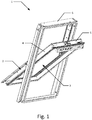
- a perspective view of a prior art roof window 1 with a sash frame 2 and a stationary frame 6 is shown.
- the sash frame 2 delimits an inner opening 3 and comprises a first frame part 4 and a second frame part 5, which are interconnected at a corner by means of a finger joint. Similar joints are used at the other three corners.
- a window pane is inserted in the inner opening 3, delimited by the sash frame 2.
- the window When the window is installed in e.g. a roof structure, it may be subject to a significant temperature and/or humidity difference from an external side of the sash frame 2, facing the exterior when the window is in a mounted condition, to an internal side of the sash frame 2, facing the interior in a mounted condition.
- the dimensions of the sash frame 2 are typically the smallest possible to provide sufficient mechanical strength.
- the sash frame 2 may be subject to material deformations, particularly shrinking and warping, due to these temperature and/or humidity differences, which may lead to the fingers of the finger joints becoming visible.
- the stationary frame 6 and/or sash frame of the window 1 are here made from wood, such as pine, but PUR, PVC, or any combination thereof, may also be employed.
- the finger joints may be press fitted, adhered, e.g. by means of adhesive, or interconnected by e.g. screws, pins, or the like.
- the first frame part 30 comprises an end surface 34 in a longitudinal direction Li of the first frame part 30.
- a transition between the end surface 34 of the first frame part 30 and the main inner surface 32 of the first frame part 30 is substantially perpendicular.
- Three first fingers 36a, 36b, 36c, each having a side surface 360a, 360b, 360c, respectively, are arranged on a protrusion 38 at the end surface 34 and extend from the end surface 34. Thereby the gaps between the first fingers 36a, 36b, 36c do not reach the end surface 34 but instead the protrusion.
- the side surfaces 360a, 360b, 360c are retracted from the first assembly plane A by a distance D 1 .
- the second frame part 40 furthermore comprises an end surface 44, from which two second fingers 46a, 46b each extend in the longitudinal direction L 2 .
- a transition between the end surface 44 of the second frame part 40 and the main inner surface 42 of the second frame part 40 is substantially perpendicular.
- the two fingers 46a, 46b each comprise a first side surface 460a, 460b, respectively, and are adapted to, in a mounted condition, engage the first fingers 36a, 36b, 36c of the first frame part 30 by being arranged in the gaps between the first fingers 36a-36c.
- the second fingers 46a, 46b are retracted from the second assembly plane B (shown in Fig.
- the first frame part 30 may move a certain distance away from the second frame part 40 along the first assembly plane A, whilst the fingers 36a-36c, 46a, 46b of the finger joint remain hidden.
- the distance is determined by the retraction distance D 2 of the second fingers 46a, 46b from the second assembly plane B and/or the protrusion 38 of the first frame part 30.
- the maximum distance, which the first frame part 30 may move whilst the fingers 36a-36c, 46a, 46b remain hidden may be e.g. up to 10 mm, such as 5 mm.
- the end surface 44 of the second frame part 40 is in mounted condition arranged on the same side of the first assembly plane A as an outer surface 37 of the first frame part 30, as shown in Fig. 2 . Consequently, the second frame part 40 may move a certain distance along the second assembly plane B whilst the fingers 36a-36c, 46a, 46b remain hidden by the first frame part 30.
- the distance which the second frame part 40 may move similarly depends on the retraction distance D 1 of the end surfaces 360a-360c of the first fingers 36a-36c from the first assembly plane A.
- this distance corresponds to the maximum distance, which the first frame part 30 may move along the first assembly plane A, e.g. 10 mm or 5 mm.
- the maximum distance, which the first frame part 30 may move along the first assembly plane A may be different from the distance
- the second frame part 40 may move along the second assembly plane B, whilst the fingers 36a-36c, 46a, 46b remain hidden from the opening defined by the frame.
- the number of first 36a-36c and second fingers 46a, 46b may be different in other embodiments. As shown in Fig. 2 and Fig.
- the first 30 and second frame part 40 have flat main inner surfaces 32, 42, respectively, and one respective minor recess 39, 49, which do not form part of the main inner surfaces 32, 42, for accommodating a pane.
- the first 30 and second frame part may include further minor recesses, grooves, and/or projections as well as gaskets, fasteners, or the like, which similarly do not form part of the main inner surfaces 32, 42.
- minor recesses 39, 49 may be configured for accommodating a sash frame 2.
- FIG. 3a a perspective view of a section of an embodiment of a first frame part 10 and a section of an embodiment of a second frame part 20 of a frame according to the present invention are shown.
- the first frame part 10 comprises a main inner surface 12 adapted to lie in a first assembly plane (not shown in Fig. 3a ) in a mounted condition.
- the first frame part 10 furthermore comprises three first fingers 16a, 16b, 16c each having a side surface 160a, 160b, 160c, respectively, which in a mounted condition face an end surface 24 of the second frame part 20.
- the side surface 160b of the centre first finger 16b is retracted from the first assembly plane.
- another of the first fingers 16a, 16c may be retracted from the first assembly plane instead of or in combination with the centre first finger 16b.
- the protrusion 28 upon engagement of the second fingers 26a, 26b with the first fingers 16a-16c, the protrusion 28 allows the second frame part 20 to move along the second assembly plane for a certain distance D 4 , determined by the length of the protrusion 28 in the longitudinal direction L 2 of the second frame part 20.
- D 4 the distance between the side surfaces 260a, 260b of the second fingers 26a, 26b may be retracted from the second assembly plane.
- Fig. 3b a perspective view of a section of another embodiment of a first frame part 50 and a section of another embodiment of a second frame part 60 of a frame according to the present invention is shown.
- the embodiment of the first frame part shown in Fig. 3b comprises a main inner surface 52, adapted to lie in a first assembly plane (not shown in Fig. 3b ), in a mounted condition, three first legs 56a, 56b, 56c, each having a respective side surface 560a, 560b, 560c, which in use face the end surface (not shown in Fig. 3b ) of the second frame part 60.
- the retraction distance D 1 of the first legs 56a-56c from the assembly plane is approximately 30% of the width of the first frame part 50 measured from a main inner surface 52 to an outer surface 57. In other embodiments, the retraction distance D 1 may be more, such as up to 60% or less, such as less than 15% of the width of the first frame part 50.
- the retraction distance D 1 determines the distance from the end surface of the second frame part 60 from the first assembly plane in a mounted condition and thereby determines the maximum distance, which the second frame part may move along its longitudinal direction L 2 , whilst hiding the fingers of the corner assembly.
- the second frame part 60 comprises two second fingers 66a, 66b, each having a respective side surface 660a, 660b, which faces the end surface 54 of the first frame part 50.
- the side surfaces 660a, 660b of the second fingers 66a, 66b lie, in this embodiment of the second frame part 60, in the second assembly plane in a mounted condition.
- a perspective view of a section of another embodiment of a first frame part 70 and a section of another embodiment of a second frame part 80 of a frame according to the present invention is shown.
- the first frame part 70 Similar to the first 50 and second frame parts 60 shown in Fig. 3b , the first frame part 70, as shown in Fig. 5 , comprises a main inner surface 72, lying in a first assembly plane A, as shown in Fig. 6 , in a mounted condition.
- the first frame part 70 additionally comprises three first legs 76a, 76b, 76c, each having a side surface 760a, 760b, 760c, which in use face an end surface 84 of the second frame part 80.
- All three first legs 76a-76c are retracted from the first assembly plane A by a distance D 1 .
- the first legs 76a, 76c furthermore comprise recesses 761a, 761c, 861 for engaging and/or connecting to a second frame part 80, as the recesses 761a, 761c, 861 provides surfaces and room for adding adhesive.
- the first frame part 70 comprises a recess 79 in the main inner surface 72 in a longitudinal direction L 1 of the first frame part 70.
- the recess 79 flushes with the side surface 760a of the first leg 76a.
- the recess 79 may be deeper or less deep, such that the distance from the first assembly plane to the surface of the recessed section, which is parallel with the main inner surface 72, is larger or smaller, respectively, than the distance D 1 from the first assembly plane to the side surfaces 760a-c of the first legs 76a-76c.
- Fig. 6 shows a corner assembly of a frame, which delimits an inner opening, comprising the first frame part 70 and the second frame part 80, as described with reference to Fig. 5 .
- the end surface 84 of the second frame part 80 is arranged adjacent to the end surfaces 760a-760c of the first fingers 76a-76c, shown in Fig. 5 .
- the fingers 76a-76c, 86a, 86b, shown in Fig. 5 of the finger joint remain hidden when seen from the inner opening, if the second frame part 80 moves up to a maximum distance in its longitudinal direction, away from the first frame part 70.
- the end surface of the second frame part 80 lies in the first assembly plane and thus flush with the main inner surface 72 of the first frame part 70. If the second frame part 80, however, moves further away from the first frame part 70, the fingers may become visible. As the movement may be caused by shrinking and/or warping of the frame material, the retraction of the first fingers 76a-76c, as shown in Fig. 5 , may be determined based on the material used for the frame parts 70, 80 and the expected weather conditions, e.g. temperature and humidity, of the frame parts 70, 80.
- a perspective view of a partly assembled corner assembly of an embodiment of a frame according to the present invention is shown.
- the corner assembly comprises a first frame part 30' having three fingers and a second frame part 40' having two fingers.
- the first frame part 30' differs from the first frame part 30 described with reference to Fig. 2 and Fig. 4 by the protrusion length D 3 , measured in the longitudinal direction L 1 of the first frame part 30'.
- the protrusion length D 3 of the first frame part 30' is approximately the same as the retraction distance (shown as D 2 for the second frame part 40 described with reference to Fig. 4 ) of the second frame part 40'.
- the retraction distance D 1 of the first fingers with respect to the first assembly plane (shown as A in Fig. 2 ) of the first frame part 30' allows for a connection with the second frame part 40', such that the end surface (not shown in Fig. 7 ) thereof is arranged on the same side of the first assembly plane as an outer surface of the first frame part.
Landscapes
- Engineering & Computer Science (AREA)
- Civil Engineering (AREA)
- Structural Engineering (AREA)
- Joining Of Corner Units Of Frames Or Wings (AREA)
Abstract
Description
- The present invention relates to a frame for a window comprising a first frame part and a second frame part, which are interconnected in a corner assembly, to a roof window comprising a frame, and to a method for assembling a corner of a frame.
- Windows, which typically include a sash frame connected to a stationary frame by means of hinges, are subject to varying surrounding conditions, such as direct sunlight and changes in humidity and temperature. This may cause the frame material to work, shrink, and warp, particularly when frame parts are made from wood or wood-based materials. This may lead to cosmetic and functional defects, such as gaps occurring at joints. When using finger joints, the occurrence of such a gap may result in the fingers, which are usually largely hidden, becoming visible. Gaps and visible fingers makes it difficult to keep the corners of the frame clean and furthermore have a negative impact on the visual appearance of the window. In
CH545904 - One solution to this problem is to use frames, which are over-moulded with a polymer, such as polyurethane (PUR), so that the joints between frame parts are covered by the moulding material. This, however, may increase the price of the windows as well as reduce the flexibility in the production as each frame size requires a separate mould.
- Alternatively, a joint sealer may be used at the corner assemblies. Though the joint sealer covers a gap, so that it is not visible, it does typically not insulate as well as the frame material and may become miscoloured over time. Moreover, the provision of a joint sealer may increase the production time and thereby the production costs.
- It is therefore an objective of the present invention to provide a frame for a window, which reduces the risk of fingers becoming visible at corner finger joints.
- According to a first aspect of the present invention, the objective is achieved with a frame for a window delimiting an inner opening, the frame comprising a first frame part and a second frame part, which are interconnected in a corner assembly, each frame part having a main inner surface facing the inner opening and an outer surface facing away from the inner opening, said first frame part comprising a plurality of first fingers extending from an end surface of said first frame part in a longitudinal direction of said first frame part, wherein the main inner surface of said first frame part lies in a first assembly plane, said second frame part comprising a plurality of second fingers extending from an end surface of said second frame part in a longitudinal direction of said second frame part and adapted for engaging with said first fingers, wherein the main inner surface of said second frame part lies in a second assembly plane, and wherein the end surface of said first frame part and the main inner surface of the first frame part meet at a substantially right angle, and wherein the end surface of said second frame part and the main inner surface of said second frame part meet at a substantially right angle, and wherein
a side surface of at least one of said first fingers, which in a mounted condition faces the end surface of the second part, is substantially parallel to and retracted from said first assembly plane, and wherein
a side surface of each of said second fingers, which in a mounted condition faces the end surface of the first part, is substantially parallel to and retracted from said second assembly plane, and/or wherein the end surface of said second frame part in a mounted condition is arranged on the same side of the first assembly plane as the outer surface of the first frame part,
so that the corner assembly displays a single joint line at the main inner surfaces of the frame parts. - By only a single joint line being displayed none of the gaps between the first plurality of fingers and the second plurality of fingers are visible when the first frame part and the second frame part are interconnected, only the single joint line where the end surface of the first frame part and the end surface of the second frame meet is visible.
- Throughout this specification, a main inner surface refers to a major surface facing and delimiting the inner opening. Where minor recesses or protrusions, e.g. for supporting or accommodating other window elements, such as panes, sashes, or stationary frames, are provided, surfaces of these are not to be understood as forming part of a main inner surface. The main inner surface will be at least partially visible to a user when the window is in a mounted condition.
- By at least one of the first fingers being retracted from the first assembly plane, the second fingers may, in a mounted condition, be arranged entirely on the same side of the first assembly plane as the outer surface of the first frame part. Hence, the second fingers will remain hidden from the inner opening of the frame, even if the second frame part moves, e.g. due to shrinking, away from the corner in its longitudinal directional. The second frame part may move approximately the same distance as the side surface of the first fingers, which are parallel to the assembly plane, are retracted from the first assembly plane without the second fingers becoming visible. The second fingers may furthermore extend from a protrusion arranged on the end surface of the second frame part.
- By the side surface of each of the second fingers furthermore being retracted from the second assembly plane, the first frame may move away from the corner in its longitudinal direction without the first fingers becoming visible. Thereby the corner assembly allows the first and second frame part to move, e.g. due to shrinking of the frame material, away from the corner in their respective longitudinal directions, whilst the corner assembly displays one joint line at the main inner surfaces of the first and second frame parts. Moreover, warping of the frame material, which may lead to uneven gaps at the joint, is hereby allowed for. Different joints and/or various embodiments or variants of a corner joint may be used at the different corners of a frame, e.g. depending on the angle from which the corner can be seen by a user, to minimise the risk of fingers becoming visible.
- By the end surface of the second frame part in a mounted condition, alternatively or additionally, being arranged on the same side of the first assembly plane as the outer surface of the first frame part, the second frame part may move up to a certain distance away from the corner, whilst the corner assembly displays one single joint line. The distance may be determined by the initial distance, in a mounted condition, from the end surface of the second frame part to the first assembly plane.
- The corner assembly may display a line towards an interior and/or exterior side of the frame, which lies in the first assembly plane, and may thus provide one single joint line towards the interior side, the inner side and the exterior side of the frame, as the joint between the two frame parts and consequently the joint line will at least partly lie at the intersection of the two assembly planes. At the joint, a strong connection between the first and second fingers, and thus between the first and second frame parts, may be achieved upon addition of a connecting means, such as adhesive, nails, screws, pins, and/or fasteners.
- By the wording frame for a window it is here to be understood that the frame may for instance be a window frame, a window sash, a door frame, or the like. The frame may e.g. be made from wood, such as pine, oak, larch, mahogany, or the like, fibreboard, such as low-, middle-, or high-density fibreboard, from a polymer material, such as polyvinyl chloride (PVC) or PUR, or from a polymer encased wooden core, such as a PUR-encased core of fibreboard material, or the like.
- According to an embodiment of the invention, the first frame part comprises three first fingers, which are parallel and each have a side surface, which in a mounted condition faces the end surface of the second part, where at least the side surface of the centre finger is substantially parallel to and retracted from the first assembly plane.
- By the first frame part comprising at least three first fingers, the first frame part provides at least four surfaces, with which the second fingers may connect. Consequently, a strong connection may be provided e.g. by use of connecting means. Furthermore, the risk of the frame parts twisting relative to each other during handling and/or assembly of the frame, which could damage the fingers and/or frame parts, may be reduced.
- By retracting the end surface of at least the centre first finger, the two second fingers, which in a mounted condition connect with the centre first finger, may be arranged on a protrusion extending a predetermined distance from the end surface of the second frame part.
- According to another embodiment, a side surface, which in a mounted condition faces the end surface of the second part, of each of the first fingers are substantially parallel to and retracted from the first assembly plane.
- Consequently, the end surface of the second frame part may, in a mounted condition, be arranged on the same side of the first assembly plane as the outer side of the first frame part. Hence, the corner assembly will display one single joint line, even if the second frame part moves away from the corner in the longitudinal direction. The second fingers may additionally be arranged on a protrusion extending from the second end surface to provide a larger corner assembly tolerance towards movement of the second frame part away from the corner.
- According to yet another embodiment, each of the first fingers has a side surface, which is flush with an outer side of said first frame part, so that an open joint is provided towards the outer side of said first frame part.
- Thereby, the first fingers may extend up to the width of the first frame part measured from the main inner surface to the outer surface of the first frame part or to the retracted side surface of the first fingers. Thus, the fingers may extend for as much as the width of the first frame part as possible. Consequently, a larger retraction of the end surfaces of the first fingers may be provided, thereby reducing the risk of fingers of the finger joints becoming visible, whilst maintaining a sufficient strength of the corner assembly.
- By the side surfaces of the first fingers being flush with an outer side of the first frame part, further connecting means, such as adhesive, a bracket, such as an angle bracket, or the like may be arranged on the outer side of the frame and provide for a stronger connection.
- According to another embodiment, the length of each of the first fingers in the longitudinal directional of said first frame part is less than or equal to the width of the second frame part measured from the outer side to the inner side of the second frame part.
- The second frame part may, consequently, not be able to move in a longitudinal direction of the first frame part, thereby allowing for an easy assembly of the frame, as the fingers of the first frame part will then be hidden from the inner opening of the frame by the second frame part. By the first fingers being shorter than the width of the second frame part, the first frame part may furthermore be allowed to move further away from the corner in its longitudinal direction before the fingers become visible.
- The fingers may furthermore be arranged to provide a gap between the side surfaces of the first fingers and the end surface and/or protrusion of the second frame part and/or vice versa. Thus, the frame material may expand and reduce the gap size rather than generating damaging tensions in the corner assembly.
- A second aspect of the present invention relates to a roof window comprising the frame according to the first aspect of the invention.
- By a roof window comprising the frame, the corner assembly of the roof window sash and/or frame may show one joint line to the inner opening of the sash and/or frame despite changes in temperature and humidity. Thus, the roof window frame and/or sash corners will be easy to clean, whilst maintaining a sufficient corner assembly strength.
- A third aspect of the present invention relates to a method for assembling a corner of a frame for a window delimiting an inner opening, the method comprising the steps of:
- providing a first frame part having a main inner surface facing the inner opening of the frame and an outer side facing away from the inner opening of the frame, said first frame part comprising plurality of first fingers extending from an end surface of said first frame part in a longitudinal direction of said first frame part, wherein the main inner surface of said first frame part lies in a first assembly plane, and wherein the end surface of said first frame part and the main inner surface of the first frame part meet at a substantially right angle,
- providing a second frame part having a main inner surface facing the inner opening of the frame and an outer side facing away from the inner opening of the frame, said second part comprising a plurality of second fingers, extending from an end surface of said second frame part in a longitudinal direction of said second frame part and adapted for engaging with said first fingers, wherein the main inner surface of said second frame part lies in a second assembly plane, and wherein the end surface of said second frame part and the main inner surface of said second frame part meet at a substantially right angle,
- aligning said first and second part such that the second fingers are aligned with spaces between said first fingers,
- adjoining said first and second parts by engaging the first fingers and second fingers with each other, so that a side surface of at least one of said first fingers, which in a mounted condition faces the end surface of the second part, is substantially parallel to and retracted from said first assembly plane, and wherein a side surface of each of said second fingers, which in a mounted condition faces the end surface of the first part, is substantially parallel to and retracted from said second assembly plane, and/or wherein the end surface of said second frame part in a mounted condition is arranged on the same side of the first assembly plane as the outer surface of the first frame part, and so that the corner assembly displays a single joint line at the main inner surfaces of the frame parts.
- Consequently, a frame may be provided, wherein the fingers may remain hidden at the corner assemblies upon movement of the first and second frame part along their respective longitudinal directions. The fingers may remain hidden for movements up to a predetermined distance. This distance is determined by a retraction distance of the end surface of the first fingers with respect to the first assembly plane, the retraction distance of the end surface of the second fingers with respect to the second assembly plane and/or to the initial distance from the end surface of the second frame part to the first assembly plane.
- According to an embodiment of the method, the method further comprises the step of:
- applying connecting means, preferably adhesive, to at least one of said first fingers and/or at least one of said second fingers.
- By applying connecting means, a stable and secure connection between the first fingers and the second fingers may be provided, such that the frame remains connected in the corner assemblies when moving the frame. By using adhesive as connecting means, the first and second fingers adhere to each other and/or to an end surface and/or to a protrusion, thus providing a particularly strong joint. Alternatively, screws, nails, bolts, nuts, and/or pins, or the like, may be used instead of or in combination with adhesive as connecting means.
- The different aspects of the present invention can be implemented in different ways including as a frame for a window, a roof window comprising a frame and a method for assembling a corner of a frame for a window as described above and in the following, each yielding one or more benefits and advantages described in connection with at least one of the aspects described above, and each having one or more preferred embodiments corresponding to the preferred embodiments described in connection with at least one of the aspects described above.
- Furthermore, it will be appreciated that embodiments described in connection with one of the aspects described herein may equally be applied to the other aspects, unless otherwise stated.
- The invention will now be described in greater detail based on nonlimiting exemplary embodiments and with reference to the drawings, of which:
-
Fig. 1 shows a perspective view of a roof window, -
Fig. 2 shows a perspective view of a corner assembly of an embodiment of a frame according to the present invention, -
Fig. 3a shows a perspective view of a section of a first frame part and a section of a second frame part of a frame according to the present invention, -
Fig. 3b shows a perspective view of a section of another embodiment of a first frame part and a section of another embodiment of a second frame part of a frame according to the present invention, -
Fig. 4 shows a perspective view of a section of yet another embodiment of a first frame part and a section of yet another embodiment of a second frame part of a frame according to the present invention, -
Fig. 5 shows a perspective view of a section of another embodiment of a first frame part and a section of another embodiment of a second frame part of a frame according to the present invention, -
Fig. 6 shows a perspective view of a partly assembled corner assembly of another embodiment of a frame according to the present invention, -
Fig. 7 shows a perspective view of a partly assembled corner assembly of an embodiment of a frame according to the present invention, -
Fig. 8 shows the corner assembly fromFig. 7 in an assembled state. - In
Fig. 1 , a perspective view of a priorart roof window 1 with asash frame 2 and astationary frame 6 is shown. Thesash frame 2 delimits aninner opening 3 and comprises afirst frame part 4 and asecond frame part 5, which are interconnected at a corner by means of a finger joint. Similar joints are used at the other three corners. A window pane is inserted in theinner opening 3, delimited by thesash frame 2. When the window is installed in e.g. a roof structure, it may be subject to a significant temperature and/or humidity difference from an external side of thesash frame 2, facing the exterior when the window is in a mounted condition, to an internal side of thesash frame 2, facing the interior in a mounted condition. To gain as much light and view as possible, the dimensions of thesash frame 2 are typically the smallest possible to provide sufficient mechanical strength. Thesash frame 2 may be subject to material deformations, particularly shrinking and warping, due to these temperature and/or humidity differences, which may lead to the fingers of the finger joints becoming visible. - The
stationary frame 6 and/or sash frame of thewindow 1 are here made from wood, such as pine, but PUR, PVC, or any combination thereof, may also be employed. Moreover, the finger joints may be press fitted, adhered, e.g. by means of adhesive, or interconnected by e.g. screws, pins, or the like. - It will be understood by the skilled person that the current invention might as well be applied to the
stationary frame 6 of theroof window 1, also delimiting an opening in which thesash frame 2 is arranged. - In
Fig. 2 , a perspective view of a corner assembly of an embodiment of a frame according to the present invention is shown. The corner assembly comprises twoframe parts Fig. 2 along with a first assembly plane A and a second assembly plane B. The assembly planes A, B furthermore defines a joint line C of the corner assembly at their intersection. The first 30 andsecond frame part 40 furthermore each comprise a maininner surface Fig. 4 . In the corner assembly ofFig. 2 , the maininner surface 32 of thefirst frame part 30 lies in the first assembly plane A. Similarly, the maininner surface 42 of thesecond frame part 40 lies in the second assembly plane B, respectively. As seen inFig. 4 , thefirst frame part 30 comprises anend surface 34 in a longitudinal direction Li of thefirst frame part 30. A transition between theend surface 34 of thefirst frame part 30 and the maininner surface 32 of thefirst frame part 30 is substantially perpendicular. Threefirst fingers side surface protrusion 38 at theend surface 34 and extend from theend surface 34. Thereby the gaps between thefirst fingers end surface 34 but instead the protrusion. Furthermore, theside surfaces - As shown in
Fig. 4 , thesecond frame part 40 furthermore comprises anend surface 44, from which twosecond fingers end surface 44 of thesecond frame part 40 and the maininner surface 42 of thesecond frame part 40 is substantially perpendicular. The twofingers first side surface first fingers first frame part 30 by being arranged in the gaps between thefirst fingers 36a-36c. Thesecond fingers Fig. 2 ) by a distance D2, which is approximately the same as the protrusion of thefirst frame part 30 extends from theend surface 34 thereof. Thus, a part of theend surface 34 of thefirst frame part 30 is arranged adjacent to the maininner surface 42 of thesecond frame part 40 in a mounted condition, as shown inFig. 2 . By means of the protrusion of thefirst frame part 30 and the retraction of thesecond fingers first frame part 30 may move a certain distance away from thesecond frame part 40 along the first assembly plane A, whilst thefingers 36a-36c, 46a, 46b of the finger joint remain hidden. The distance is determined by the retraction distance D2 of thesecond fingers protrusion 38 of thefirst frame part 30. In some embodiments, the maximum distance, which thefirst frame part 30 may move whilst thefingers 36a-36c, 46a, 46b remain hidden may be e.g. up to 10 mm, such as 5 mm. - Similarly, by the
side surfaces 360a-360c of thefirst fingers 36a-36c being retracted from the first assembly plane A, theend surface 44 of thesecond frame part 40 is in mounted condition arranged on the same side of the first assembly plane A as anouter surface 37 of thefirst frame part 30, as shown inFig. 2 . Consequently, thesecond frame part 40 may move a certain distance along the second assembly plane B whilst thefingers 36a-36c, 46a, 46b remain hidden by thefirst frame part 30. The distance which thesecond frame part 40 may move similarly depends on the retraction distance D1 of theend surfaces 360a-360c of thefirst fingers 36a-36c from the first assembly plane A. In some embodiments, this distance corresponds to the maximum distance, which thefirst frame part 30 may move along the first assembly plane A, e.g. 10 mm or 5 mm. In other embodiments, the maximum distance, which thefirst frame part 30 may move along the first assembly plane A, may be different from the distance, thesecond frame part 40 may move along the second assembly plane B, whilst thefingers 36a-36c, 46a, 46b remain hidden from the opening defined by the frame. Moreover, the number of first 36a-36c andsecond fingers Fig. 2 and Fig. 4 , the first 30 andsecond frame part 40, have flat maininner surfaces minor recess inner surfaces inner surfaces stationary frame 6 for a roof window,minor recesses sash frame 2. - In
Fig. 3a , a perspective view of a section of an embodiment of afirst frame part 10 and a section of an embodiment of asecond frame part 20 of a frame according to the present invention are shown. Thefirst frame part 10 comprises a maininner surface 12 adapted to lie in a first assembly plane (not shown inFig. 3a ) in a mounted condition. Thefirst frame part 10 furthermore comprises threefirst fingers side surface end surface 24 of thesecond frame part 20. Theside surface 160b of the centrefirst finger 16b is retracted from the first assembly plane. In another embodiment, another of thefirst fingers first finger 16b. - Similarly, the
second frame part 20 comprises a maininner surface 22 adapted to lie in a second assembly plane (not shown inFig. 3a ), and twosecond fingers side surface end surface 14 of thefirst frame part 10. The side surfaces 260a, 260b of thesecond fingers second fingers protrusion 28 at the end surface of thesecond frame part 20. In a mounted condition, i.e. upon engagement of thesecond fingers first fingers 16a-16c, theprotrusion 28 allows thesecond frame part 20 to move along the second assembly plane for a certain distance D4, determined by the length of theprotrusion 28 in the longitudinal direction L2 of thesecond frame part 20. In another embodiment, only one of theside surfaces second fingers - In
Fig. 3b , a perspective view of a section of another embodiment of afirst frame part 50 and a section of another embodiment of asecond frame part 60 of a frame according to the present invention is shown. Similar to the embodiment of thefirst frame part 10 shown inFig. 3a , the embodiment of the first frame part shown inFig. 3b comprises a maininner surface 52, adapted to lie in a first assembly plane (not shown inFig. 3b ), in a mounted condition, threefirst legs respective side surface Fig. 3b ) of thesecond frame part 60. In this embodiment of thefirst frame part 50, however, all threefirst legs 56a-56c are retracted from the first assembly plane. The retraction distance D1 of thefirst legs 56a-56c from the assembly plane is approximately 30% of the width of thefirst frame part 50 measured from a maininner surface 52 to anouter surface 57. In other embodiments, the retraction distance D1 may be more, such as up to 60% or less, such as less than 15% of the width of thefirst frame part 50. The retraction distance D1 determines the distance from the end surface of thesecond frame part 60 from the first assembly plane in a mounted condition and thereby determines the maximum distance, which the second frame part may move along its longitudinal direction L2, whilst hiding the fingers of the corner assembly. - Similarly, the
second frame part 60 comprises twosecond fingers respective side surface end surface 54 of thefirst frame part 50. The side surfaces 660a, 660b of thesecond fingers second frame part 60, in the second assembly plane in a mounted condition. - In
Fig. 5 , a perspective view of a section of another embodiment of afirst frame part 70 and a section of another embodiment of asecond frame part 80 of a frame according to the present invention is shown. Similar to the first 50 andsecond frame parts 60 shown inFig. 3b , thefirst frame part 70, as shown inFig. 5 , comprises a maininner surface 72, lying in a first assembly plane A, as shown inFig. 6 , in a mounted condition. Thefirst frame part 70 additionally comprises threefirst legs side surface end surface 84 of thesecond frame part 80. All threefirst legs 76a-76c are retracted from the first assembly plane A by a distance D1. Thefirst legs recesses second frame part 80, as therecesses - Moreover, the
first frame part 70 comprises arecess 79 in the maininner surface 72 in a longitudinal direction L1 of thefirst frame part 70. Therecess 79, as shown inFig. 5 flushes with theside surface 760a of thefirst leg 76a. In another embodiment of thefirst frame part 70, therecess 79 may be deeper or less deep, such that the distance from the first assembly plane to the surface of the recessed section, which is parallel with the maininner surface 72, is larger or smaller, respectively, than the distance D1 from the first assembly plane to the side surfaces 760a-c of thefirst legs 76a-76c. - The
second frame part 80 comprises twosecond legs side surface end surface 74 of thefirst frame part 70 and lying in the second assembly plane B, shown inFig. 6 . Similar to thefirst legs second leg 86a comprises a recess to engage with thefirst leg 76a. In another embodiment, another first and/or second leg may instead of or in addition to thefirst legs second leg 86a comprise recesses. Alternatively, no recesses may be provided in the first 76a-76c and/orsecond legs -
Fig. 6 shows a corner assembly of a frame, which delimits an inner opening, comprising thefirst frame part 70 and thesecond frame part 80, as described with reference toFig. 5 . Upon assembly of the corner assembly shown inFig. 6 , theend surface 84 of thesecond frame part 80 is arranged adjacent to theend surfaces 760a-760c of thefirst fingers 76a-76c, shown inFig. 5 . Thereby, thefingers 76a-76c, 86a, 86b, shown inFig. 5 , of the finger joint remain hidden when seen from the inner opening, if thesecond frame part 80 moves up to a maximum distance in its longitudinal direction, away from thefirst frame part 70. At the maximum distance, the end surface of thesecond frame part 80 lies in the first assembly plane and thus flush with the maininner surface 72 of thefirst frame part 70. If thesecond frame part 80, however, moves further away from thefirst frame part 70, the fingers may become visible. As the movement may be caused by shrinking and/or warping of the frame material, the retraction of thefirst fingers 76a-76c, as shown inFig. 5 , may be determined based on the material used for theframe parts frame parts - In
Fig. 7 , a perspective view of a partly assembled corner assembly of an embodiment of a frame according to the present invention is shown. The corner assembly comprises afirst frame part 30' having three fingers and a second frame part 40' having two fingers. Thefirst frame part 30' differs from thefirst frame part 30 described with reference toFig. 2 and Fig. 4 by the protrusion length D3, measured in the longitudinal direction L1 of thefirst frame part 30'. The protrusion length D3 of thefirst frame part 30' is approximately the same as the retraction distance (shown as D2 for thesecond frame part 40 described with reference toFig. 4 ) of the second frame part 40'. Similarly, the retraction distance D1 of the first fingers with respect to the first assembly plane (shown as A inFig. 2 ) of thefirst frame part 30' allows for a connection with the second frame part 40', such that the end surface (not shown inFig. 7 ) thereof is arranged on the same side of the first assembly plane as an outer surface of the first frame part. - Hence, if in an assembled state, the
first frame part 30' has moved away from the corner assembly along its longitudinal direction L1, as shown inFig. 8 , a gap with a gap length G1 is formed. Due to the protrusion length D3 of thefirst frame part 30', the fingers remain hidden, when seen from the inner opening, as long as the gap length G1 is smaller than or equal to the protrusion length D3. Similarly, if the second frame part 40' moves away from the corner assembly in its longitudinal direction L2, a gap with a gap length G2 is formed, which does not expose the fingers of the joint, as long the gap length G2 is smaller than or equal to the retraction distance D1. The protrusion length D3 and the retraction distance D1 may therefore be adapted at different corners of a frame in various embodiments of a frame to be able to accommodate the maximum expected movement of theframe parts 30', 40'. - Factors such as the thermal coefficient of expansion of the material(s) used and any expected creeping, shrinkage, or other dimensional changes due for example to changes in atmospheric humidity should be taken into account when determining retraction distances and protrusion lengths. This applies to all embodiments of the invention.
- The skilled person will furthermore appreciate that details from the first embodiment of the
frame parts frame parts Figs. 3a, 3b ,5, and 6 . - Although some embodiments have been described and shown in detail, the invention is not restricted to them, but may also be embodied in other ways within the scope of the subject matter defined in the following claims. In particular, it is to be understood that other embodiments may be utilised and structural as well as functional modifications may be made without departing from the scope of the present invention. It should furthermore be emphasised that the term "comprises"/"comprising" when used in this specification is taken to specify the presence of stated features, integers, steps, or components but not preclude the presence or addition of one or more features, integers, steps, components, or groups thereof.
-
- 1
- Roof window
- 2
- Sash frame
- 3
- Inner opening
- 4
- First frame part
- 5
- Second frame part
- 6
- Stationary frame
- 10
- First frame part
- 12
- Main inner surface
- 14
- End surface
- 16a-16c
- First fingers
- 160a-160c
- Side surfaces
- 20
- Second frame part
- 22
- Main inner surface
- 24
- End surface
- 26a, 26b
- Second fingers
- 260a, 260b
- Side surfaces
- 28
- Protrusion
- 30
- First frame part
- 32
- Main inner surface
- 34
- End surface
- 36a-36c
- First fingers
- 360a-360c
- Side surfaces
- 37
- Outer surface
- 38
- Protrusion
- 39
- Recess
- 40
- Second frame part
- 42
- Main inner surface
- 44
- End surface
- 46a, 46b
- Second fingers
- 460a, 460b
- Side surfaces
- 49
- Recess
- 50
- First frame part
- 52
- Main inner surface
- 54
- End surface
- 56a-56c
- First fingers
- 560a-560c
- Side surfaces
- 57
- Outer surface
- 60
- Second frame part
- 62
- Main inner surface
- 66a, 66b
- Second fingers
- 660a, 660b
- Side surfaces
- 70
- First frame part
- 72
- Main inner surface
- 74
- End surface
- 76a-76c
- First fingers
- 760a-760c
- Side surfaces
- 761a,761c
- Recesses
- 79
- Recess
- 80
- Second frame part
- 82
- Main inner surface
- 84
- End surface
- 86a, 86b
- Second fingers
- 860a, 860b
- Side surfaces
- 861
- Recess
- A
- First assembly plane
- B
- Second assembly plane
- C
- Joint line
- D1
- Retraction distance
- D2
- Retraction distance
- D3
- Protrusion length
- D4
- Protrusion length
- G1
- Gap length
- G2
- Gap length
- L1
- Longitudinal direction
- L2
- Longitudinal direction
Claims (8)
- A frame for a window delimiting an inner opening, the frame comprising a first frame part and a second frame part, which are interconnected in a corner assembly, each frame part having a main inner surface facing the inner opening and an outer surface facing away from the inner opening, said first frame part comprising a plurality of first fingers extending from an end surface of said first frame part in a longitudinal direction of said first frame part, wherein the main inner surface of said first frame part lies in a first assembly plane, said second frame part comprising a plurality of second fingers extending from an end surface of said second frame part in a longitudinal direction of said second frame part and adapted for engaging with said first fingers, wherein the main inner surface of said second frame part lies in a second assembly plane, and wherein the end surface of said first frame part and the main inner surface of the first frame part meet at a substantially right angle, and wherein the end surface of said second frame part and the main inner surface of said second frame part meet at a substantially right angle, and wherein
a side surface of at least one of said first fingers, which in a mounted condition faces the end surface of the second part, is substantially parallel to and retracted from said first assembly plane, and wherein
a side surface of each of said second fingers, which in a mounted condition faces the end surface of the first part, is substantially parallel to and retracted from said second assembly plane, and/or wherein
the end surface of said second frame part in a mounted condition is arranged on the same side of the first assembly plane as the outer surface of the first frame part,
so that the corner assembly displays a single joint line at the inner surfaces of the frame parts. - The frame according to claim 1, wherein the first frame part comprises three first fingers, which are parallel and each have a side surface, which in a mounted condition faces the end surface of the second part, where at least the side surface of the centre finger is substantially parallel to and retracted from the first assembly plane.
- The frame according to claim 1 or 2, wherein a side surface, which in a mounted condition faces the end surface of the second part, of each of the first fingers are substantially parallel to and retracted from the first assembly plane.
- The frame according to any one of the preceding claims, wherein each of the first fingers has a side surface, which is flush with an outer side of said first frame part, so that an open joint is provided towards the outer side of said first frame part.
- The frame according to any one of the preceding claims, wherein the length of each of the first fingers in the longitudinal directional of said first frame part is less than or equal to the width of the second frame part measured from the outer side to the inner side of the second frame part.
- A roof window comprising a frame according to one or more of the preceding claims.
- A method for assembling a corner of a frame for a window delimiting an inner opening, the method comprising the steps of:- providing a first frame part having a main inner surface facing the inner opening of the frame and an outer side facing away from the inner opening of the frame, said first frame part comprising plurality of first fingers extending from an end surface of said first frame part in a longitudinal direction of said first frame part, wherein the main inner surface of said first frame part lies in a first assembly plane, and wherein the end surface of said first frame part and the main inner surface of the first frame part meet at a substantially right angle,- providing a second frame part having a main inner surface facing the inner opening of the frame and an outer side facing away from the inner opening of the frame, said second part comprising a plurality of second fingers, extending from an end surface of said second frame part in a longitudinal direction of said second frame part and adapted for engaging with said first fingers, wherein the main inner surface of said second frame part lies in a second assembly plane, and wherein the end surface of said second frame part and the main inner surface of said second frame part meet at a substantially right angle,- aligning said first and second part such that the second fingers are aligned with spaces between said first fingers,- adjoining said first and second parts by engaging the first fingers and second fingers with each other, so that a side surface of at least one of said first fingers, which in a mounted condition faces the end surface of the second part, is substantially parallel to and retracted from said first assembly plane, and wherein a side surface of each of said second fingers, which in a mounted condition faces the end surface of the first part, is substantially parallel to and retracted from said second assembly plane, and/or wherein the end surface of said second frame part in a mounted condition is arranged on the same side of the first assembly plane as the outer surface of the first frame part, and so that the corner assembly displays a single joint line at the main inner surfaces of the frame parts.
- The method for assembling a corner of a frame according to claim 7 further comprising the step of:- applying connecting means, preferably adhesive, to at least one of said first fingers and/or at least one of said second fingers.
Applications Claiming Priority (1)
| Application Number | Priority Date | Filing Date | Title |
|---|---|---|---|
| EP18184479.6A EP3597851B1 (en) | 2018-07-19 | 2018-07-19 | Corner assembly and method for assembling a corner of a frame for a window |
Publications (2)
| Publication Number | Publication Date |
|---|---|
| EP3597852A1 true EP3597852A1 (en) | 2020-01-22 |
| EP3597852B1 EP3597852B1 (en) | 2022-12-07 |
Family
ID=63012905
Family Applications (2)
| Application Number | Title | Priority Date | Filing Date |
|---|---|---|---|
| EP18184479.6A Active EP3597851B1 (en) | 2018-07-19 | 2018-07-19 | Corner assembly and method for assembling a corner of a frame for a window |
| EP19186077.4A Active EP3597852B1 (en) | 2018-07-19 | 2019-07-12 | Corner assembly and method for assembling a corner of a frame for a window |
Family Applications Before (1)
| Application Number | Title | Priority Date | Filing Date |
|---|---|---|---|
| EP18184479.6A Active EP3597851B1 (en) | 2018-07-19 | 2018-07-19 | Corner assembly and method for assembling a corner of a frame for a window |
Country Status (2)
| Country | Link |
|---|---|
| EP (2) | EP3597851B1 (en) |
| PL (2) | PL3597851T3 (en) |
Citations (4)
| Publication number | Priority date | Publication date | Assignee | Title |
|---|---|---|---|---|
| CH545904A (en) | 1972-04-27 | 1974-02-15 | ||
| DE4323628C1 (en) * | 1993-07-15 | 1995-01-05 | Hirsch Wilhelm | Sash frame and method for manufacturing the first (vertical) frame wood therefor |
| EP0964128A2 (en) * | 1998-06-12 | 1999-12-15 | Alpi Fenster GmbH - Srl | Combined joining system for door frames and window frames |
| FR3051505A1 (en) * | 2016-05-18 | 2017-11-24 | Soc D'exploitation Des Etablissements Edoli | WOOD WINDOW JOINERY |
-
2018
- 2018-07-19 EP EP18184479.6A patent/EP3597851B1/en active Active
- 2018-07-19 PL PL18184479.6T patent/PL3597851T3/en unknown
-
2019
- 2019-07-12 PL PL19186077.4T patent/PL3597852T3/en unknown
- 2019-07-12 EP EP19186077.4A patent/EP3597852B1/en active Active
Patent Citations (4)
| Publication number | Priority date | Publication date | Assignee | Title |
|---|---|---|---|---|
| CH545904A (en) | 1972-04-27 | 1974-02-15 | ||
| DE4323628C1 (en) * | 1993-07-15 | 1995-01-05 | Hirsch Wilhelm | Sash frame and method for manufacturing the first (vertical) frame wood therefor |
| EP0964128A2 (en) * | 1998-06-12 | 1999-12-15 | Alpi Fenster GmbH - Srl | Combined joining system for door frames and window frames |
| FR3051505A1 (en) * | 2016-05-18 | 2017-11-24 | Soc D'exploitation Des Etablissements Edoli | WOOD WINDOW JOINERY |
Also Published As
| Publication number | Publication date |
|---|---|
| EP3597851A1 (en) | 2020-01-22 |
| PL3597852T3 (en) | 2023-04-24 |
| EP3597852B1 (en) | 2022-12-07 |
| PL3597851T3 (en) | 2022-08-16 |
| EP3597851B1 (en) | 2022-04-27 |
Similar Documents
| Publication | Publication Date | Title |
|---|---|---|
| US12196032B2 (en) | Frame profile of an outer frame and/or leaf frame, and method for the production thereof | |
| CA2207190C (en) | Door jamb system with protective stop and jamb cladding | |
| US6745523B2 (en) | Fastening member for a window and door assembly | |
| CA2764793C (en) | A profile bar to be locked to a panel, and a panel system | |
| EP4018050B1 (en) | Curtain wall | |
| US20080245001A1 (en) | Window Cladding Device, Method and System | |
| US10801248B2 (en) | Door assembly | |
| EP2287432B1 (en) | System of outwardly opening window assemblies | |
| WO1999032751A1 (en) | Building elements | |
| EP3597852B1 (en) | Corner assembly and method for assembling a corner of a frame for a window | |
| JP5737865B2 (en) | Joint method between opening device and outer wall material | |
| US7937904B2 (en) | Corner joint for pultruded window frame | |
| US20200378178A1 (en) | Exterior door and methods for forming exterior doors | |
| GB2565255A (en) | Seal element, assembly, and method | |
| KR102206073B1 (en) | Finishing material for window cover | |
| US20020139071A1 (en) | Composite climate seal frame member assembly and method of manufacturing | |
| EP3721024A1 (en) | Curtain wall | |
| AU2020103981B4 (en) | Fixing system for architectural mouldings | |
| RU89582U1 (en) | WINDOW AND DOOR FINISHING SYSTEM | |
| JP2014227658A (en) | Doorway foot and floor edge member | |
| JP4000525B2 (en) | Panel body | |
| WO2005085552A1 (en) | Assembly for securing panels to a support structure | |
| CN104053848B (en) | Corner cladding profiles | |
| GB2382098A (en) | Frame arrangement with cladding members | |
| WO2009024816A1 (en) | Improvements in windows |
Legal Events
| Date | Code | Title | Description |
|---|---|---|---|
| PUAI | Public reference made under article 153(3) epc to a published international application that has entered the european phase |
Free format text: ORIGINAL CODE: 0009012 |
|
| STAA | Information on the status of an ep patent application or granted ep patent |
Free format text: STATUS: THE APPLICATION HAS BEEN PUBLISHED |
|
| AK | Designated contracting states |
Kind code of ref document: A1 Designated state(s): AL AT BE BG CH CY CZ DE DK EE ES FI FR GB GR HR HU IE IS IT LI LT LU LV MC MK MT NL NO PL PT RO RS SE SI SK SM TR |
|
| AX | Request for extension of the european patent |
Extension state: BA ME |
|
| STAA | Information on the status of an ep patent application or granted ep patent |
Free format text: STATUS: REQUEST FOR EXAMINATION WAS MADE |
|
| 17P | Request for examination filed |
Effective date: 20200326 |
|
| RBV | Designated contracting states (corrected) |
Designated state(s): AL AT BE BG CH CY CZ DE DK EE ES FI FR GB GR HR HU IE IS IT LI LT LU LV MC MK MT NL NO PL PT RO RS SE SI SK SM TR |
|
| STAA | Information on the status of an ep patent application or granted ep patent |
Free format text: STATUS: EXAMINATION IS IN PROGRESS |
|
| 17Q | First examination report despatched |
Effective date: 20211215 |
|
| GRAP | Despatch of communication of intention to grant a patent |
Free format text: ORIGINAL CODE: EPIDOSNIGR1 |
|
| STAA | Information on the status of an ep patent application or granted ep patent |
Free format text: STATUS: GRANT OF PATENT IS INTENDED |
|
| INTG | Intention to grant announced |
Effective date: 20220729 |
|
| GRAS | Grant fee paid |
Free format text: ORIGINAL CODE: EPIDOSNIGR3 |
|
| GRAA | (expected) grant |
Free format text: ORIGINAL CODE: 0009210 |
|
| STAA | Information on the status of an ep patent application or granted ep patent |
Free format text: STATUS: THE PATENT HAS BEEN GRANTED |
|
| AK | Designated contracting states |
Kind code of ref document: B1 Designated state(s): AL AT BE BG CH CY CZ DE DK EE ES FI FR GB GR HR HU IE IS IT LI LT LU LV MC MK MT NL NO PL PT RO RS SE SI SK SM TR |
|
| REG | Reference to a national code |
Ref country code: GB Ref legal event code: FG4D |
|
| REG | Reference to a national code |
Ref country code: CH Ref legal event code: EP Ref country code: AT Ref legal event code: REF Ref document number: 1536403 Country of ref document: AT Kind code of ref document: T Effective date: 20221215 |
|
| REG | Reference to a national code |
Ref country code: DE Ref legal event code: R096 Ref document number: 602019022784 Country of ref document: DE |
|
| REG | Reference to a national code |
Ref country code: IE Ref legal event code: FG4D |
|
| REG | Reference to a national code |
Ref country code: LT Ref legal event code: MG9D |
|
| REG | Reference to a national code |
Ref country code: NL Ref legal event code: MP Effective date: 20221207 |
|
| PG25 | Lapsed in a contracting state [announced via postgrant information from national office to epo] |
Ref country code: SE Free format text: LAPSE BECAUSE OF FAILURE TO SUBMIT A TRANSLATION OF THE DESCRIPTION OR TO PAY THE FEE WITHIN THE PRESCRIBED TIME-LIMIT Effective date: 20221207 Ref country code: NO Free format text: LAPSE BECAUSE OF FAILURE TO SUBMIT A TRANSLATION OF THE DESCRIPTION OR TO PAY THE FEE WITHIN THE PRESCRIBED TIME-LIMIT Effective date: 20230307 Ref country code: LT Free format text: LAPSE BECAUSE OF FAILURE TO SUBMIT A TRANSLATION OF THE DESCRIPTION OR TO PAY THE FEE WITHIN THE PRESCRIBED TIME-LIMIT Effective date: 20221207 Ref country code: FI Free format text: LAPSE BECAUSE OF FAILURE TO SUBMIT A TRANSLATION OF THE DESCRIPTION OR TO PAY THE FEE WITHIN THE PRESCRIBED TIME-LIMIT Effective date: 20221207 Ref country code: ES Free format text: LAPSE BECAUSE OF FAILURE TO SUBMIT A TRANSLATION OF THE DESCRIPTION OR TO PAY THE FEE WITHIN THE PRESCRIBED TIME-LIMIT Effective date: 20221207 |
|
| REG | Reference to a national code |
Ref country code: AT Ref legal event code: MK05 Ref document number: 1536403 Country of ref document: AT Kind code of ref document: T Effective date: 20221207 |
|
| PG25 | Lapsed in a contracting state [announced via postgrant information from national office to epo] |
Ref country code: RS Free format text: LAPSE BECAUSE OF FAILURE TO SUBMIT A TRANSLATION OF THE DESCRIPTION OR TO PAY THE FEE WITHIN THE PRESCRIBED TIME-LIMIT Effective date: 20221207 Ref country code: LV Free format text: LAPSE BECAUSE OF FAILURE TO SUBMIT A TRANSLATION OF THE DESCRIPTION OR TO PAY THE FEE WITHIN THE PRESCRIBED TIME-LIMIT Effective date: 20221207 Ref country code: HR Free format text: LAPSE BECAUSE OF FAILURE TO SUBMIT A TRANSLATION OF THE DESCRIPTION OR TO PAY THE FEE WITHIN THE PRESCRIBED TIME-LIMIT Effective date: 20221207 Ref country code: GR Free format text: LAPSE BECAUSE OF FAILURE TO SUBMIT A TRANSLATION OF THE DESCRIPTION OR TO PAY THE FEE WITHIN THE PRESCRIBED TIME-LIMIT Effective date: 20230308 |
|
| PG25 | Lapsed in a contracting state [announced via postgrant information from national office to epo] |
Ref country code: NL Free format text: LAPSE BECAUSE OF FAILURE TO SUBMIT A TRANSLATION OF THE DESCRIPTION OR TO PAY THE FEE WITHIN THE PRESCRIBED TIME-LIMIT Effective date: 20221207 |
|
| PG25 | Lapsed in a contracting state [announced via postgrant information from national office to epo] |
Ref country code: SM Free format text: LAPSE BECAUSE OF FAILURE TO SUBMIT A TRANSLATION OF THE DESCRIPTION OR TO PAY THE FEE WITHIN THE PRESCRIBED TIME-LIMIT Effective date: 20221207 Ref country code: RO Free format text: LAPSE BECAUSE OF FAILURE TO SUBMIT A TRANSLATION OF THE DESCRIPTION OR TO PAY THE FEE WITHIN THE PRESCRIBED TIME-LIMIT Effective date: 20221207 Ref country code: PT Free format text: LAPSE BECAUSE OF FAILURE TO SUBMIT A TRANSLATION OF THE DESCRIPTION OR TO PAY THE FEE WITHIN THE PRESCRIBED TIME-LIMIT Effective date: 20230410 Ref country code: EE Free format text: LAPSE BECAUSE OF FAILURE TO SUBMIT A TRANSLATION OF THE DESCRIPTION OR TO PAY THE FEE WITHIN THE PRESCRIBED TIME-LIMIT Effective date: 20221207 Ref country code: CZ Free format text: LAPSE BECAUSE OF FAILURE TO SUBMIT A TRANSLATION OF THE DESCRIPTION OR TO PAY THE FEE WITHIN THE PRESCRIBED TIME-LIMIT Effective date: 20221207 Ref country code: AT Free format text: LAPSE BECAUSE OF FAILURE TO SUBMIT A TRANSLATION OF THE DESCRIPTION OR TO PAY THE FEE WITHIN THE PRESCRIBED TIME-LIMIT Effective date: 20221207 |
|
| PG25 | Lapsed in a contracting state [announced via postgrant information from national office to epo] |
Ref country code: SK Free format text: LAPSE BECAUSE OF FAILURE TO SUBMIT A TRANSLATION OF THE DESCRIPTION OR TO PAY THE FEE WITHIN THE PRESCRIBED TIME-LIMIT Effective date: 20221207 Ref country code: IS Free format text: LAPSE BECAUSE OF FAILURE TO SUBMIT A TRANSLATION OF THE DESCRIPTION OR TO PAY THE FEE WITHIN THE PRESCRIBED TIME-LIMIT Effective date: 20230407 Ref country code: AL Free format text: LAPSE BECAUSE OF FAILURE TO SUBMIT A TRANSLATION OF THE DESCRIPTION OR TO PAY THE FEE WITHIN THE PRESCRIBED TIME-LIMIT Effective date: 20221207 |
|
| REG | Reference to a national code |
Ref country code: DE Ref legal event code: R097 Ref document number: 602019022784 Country of ref document: DE |
|
| PLBE | No opposition filed within time limit |
Free format text: ORIGINAL CODE: 0009261 |
|
| STAA | Information on the status of an ep patent application or granted ep patent |
Free format text: STATUS: NO OPPOSITION FILED WITHIN TIME LIMIT |
|
| PG25 | Lapsed in a contracting state [announced via postgrant information from national office to epo] |
Ref country code: DK Free format text: LAPSE BECAUSE OF FAILURE TO SUBMIT A TRANSLATION OF THE DESCRIPTION OR TO PAY THE FEE WITHIN THE PRESCRIBED TIME-LIMIT Effective date: 20221207 |
|
| 26N | No opposition filed |
Effective date: 20230908 |
|
| PG25 | Lapsed in a contracting state [announced via postgrant information from national office to epo] |
Ref country code: SI Free format text: LAPSE BECAUSE OF FAILURE TO SUBMIT A TRANSLATION OF THE DESCRIPTION OR TO PAY THE FEE WITHIN THE PRESCRIBED TIME-LIMIT Effective date: 20221207 |
|
| PG25 | Lapsed in a contracting state [announced via postgrant information from national office to epo] |
Ref country code: MC Free format text: LAPSE BECAUSE OF FAILURE TO SUBMIT A TRANSLATION OF THE DESCRIPTION OR TO PAY THE FEE WITHIN THE PRESCRIBED TIME-LIMIT Effective date: 20221207 |
|
| PG25 | Lapsed in a contracting state [announced via postgrant information from national office to epo] |
Ref country code: MC Free format text: LAPSE BECAUSE OF FAILURE TO SUBMIT A TRANSLATION OF THE DESCRIPTION OR TO PAY THE FEE WITHIN THE PRESCRIBED TIME-LIMIT Effective date: 20221207 |
|
| REG | Reference to a national code |
Ref country code: CH Ref legal event code: PL |
|
| REG | Reference to a national code |
Ref country code: BE Ref legal event code: MM Effective date: 20230731 |
|
| PG25 | Lapsed in a contracting state [announced via postgrant information from national office to epo] |
Ref country code: LU Free format text: LAPSE BECAUSE OF NON-PAYMENT OF DUE FEES Effective date: 20230712 |
|
| PG25 | Lapsed in a contracting state [announced via postgrant information from national office to epo] |
Ref country code: LU Free format text: LAPSE BECAUSE OF NON-PAYMENT OF DUE FEES Effective date: 20230712 |
|
| REG | Reference to a national code |
Ref country code: IE Ref legal event code: MM4A |
|
| PG25 | Lapsed in a contracting state [announced via postgrant information from national office to epo] |
Ref country code: CH Free format text: LAPSE BECAUSE OF NON-PAYMENT OF DUE FEES Effective date: 20230731 |
|
| PG25 | Lapsed in a contracting state [announced via postgrant information from national office to epo] |
Ref country code: IT Free format text: LAPSE BECAUSE OF FAILURE TO SUBMIT A TRANSLATION OF THE DESCRIPTION OR TO PAY THE FEE WITHIN THE PRESCRIBED TIME-LIMIT Effective date: 20221207 Ref country code: BE Free format text: LAPSE BECAUSE OF NON-PAYMENT OF DUE FEES Effective date: 20230731 |
|
| PG25 | Lapsed in a contracting state [announced via postgrant information from national office to epo] |
Ref country code: IE Free format text: LAPSE BECAUSE OF NON-PAYMENT OF DUE FEES Effective date: 20230712 |
|
| PG25 | Lapsed in a contracting state [announced via postgrant information from national office to epo] |
Ref country code: IE Free format text: LAPSE BECAUSE OF NON-PAYMENT OF DUE FEES Effective date: 20230712 |
|
| PG25 | Lapsed in a contracting state [announced via postgrant information from national office to epo] |
Ref country code: BG Free format text: LAPSE BECAUSE OF FAILURE TO SUBMIT A TRANSLATION OF THE DESCRIPTION OR TO PAY THE FEE WITHIN THE PRESCRIBED TIME-LIMIT Effective date: 20221207 |
|
| PG25 | Lapsed in a contracting state [announced via postgrant information from national office to epo] |
Ref country code: BG Free format text: LAPSE BECAUSE OF FAILURE TO SUBMIT A TRANSLATION OF THE DESCRIPTION OR TO PAY THE FEE WITHIN THE PRESCRIBED TIME-LIMIT Effective date: 20221207 |
|
| PGFP | Annual fee paid to national office [announced via postgrant information from national office to epo] |
Ref country code: PL Payment date: 20250612 Year of fee payment: 7 |
|
| PGFP | Annual fee paid to national office [announced via postgrant information from national office to epo] |
Ref country code: GB Payment date: 20250605 Year of fee payment: 7 |
|
| PGFP | Annual fee paid to national office [announced via postgrant information from national office to epo] |
Ref country code: FR Payment date: 20250610 Year of fee payment: 7 |
|
| PG25 | Lapsed in a contracting state [announced via postgrant information from national office to epo] |
Ref country code: CY Free format text: LAPSE BECAUSE OF FAILURE TO SUBMIT A TRANSLATION OF THE DESCRIPTION OR TO PAY THE FEE WITHIN THE PRESCRIBED TIME-LIMIT; INVALID AB INITIO Effective date: 20190712 |
|
| PG25 | Lapsed in a contracting state [announced via postgrant information from national office to epo] |
Ref country code: HU Free format text: LAPSE BECAUSE OF FAILURE TO SUBMIT A TRANSLATION OF THE DESCRIPTION OR TO PAY THE FEE WITHIN THE PRESCRIBED TIME-LIMIT; INVALID AB INITIO Effective date: 20190712 |
|
| PGFP | Annual fee paid to national office [announced via postgrant information from national office to epo] |
Ref country code: DE Payment date: 20250604 Year of fee payment: 7 |
|
| PG25 | Lapsed in a contracting state [announced via postgrant information from national office to epo] |
Ref country code: TR Free format text: LAPSE BECAUSE OF FAILURE TO SUBMIT A TRANSLATION OF THE DESCRIPTION OR TO PAY THE FEE WITHIN THE PRESCRIBED TIME-LIMIT Effective date: 20221207 |