EP3597793A1 - Method for electrochemically producing hydrogel, method for producing hydrogel having pattern formed of cells, hydrogel production device, and transducer - Google Patents
Method for electrochemically producing hydrogel, method for producing hydrogel having pattern formed of cells, hydrogel production device, and transducer Download PDFInfo
- Publication number
- EP3597793A1 EP3597793A1 EP18767765.3A EP18767765A EP3597793A1 EP 3597793 A1 EP3597793 A1 EP 3597793A1 EP 18767765 A EP18767765 A EP 18767765A EP 3597793 A1 EP3597793 A1 EP 3597793A1
- Authority
- EP
- European Patent Office
- Prior art keywords
- hydrogel
- sub
- pattern
- electrode
- working electrodes
- Prior art date
- Legal status (The legal status is an assumption and is not a legal conclusion. Google has not performed a legal analysis and makes no representation as to the accuracy of the status listed.)
- Granted
Links
Images





Classifications
-
- C—CHEMISTRY; METALLURGY
- C25—ELECTROLYTIC OR ELECTROPHORETIC PROCESSES; APPARATUS THEREFOR
- C25B—ELECTROLYTIC OR ELECTROPHORETIC PROCESSES FOR THE PRODUCTION OF COMPOUNDS OR NON-METALS; APPARATUS THEREFOR
- C25B3/00—Electrolytic production of organic compounds
- C25B3/01—Products
- C25B3/07—Oxygen containing compounds
-
- C—CHEMISTRY; METALLURGY
- C25—ELECTROLYTIC OR ELECTROPHORETIC PROCESSES; APPARATUS THEREFOR
- C25B—ELECTROLYTIC OR ELECTROPHORETIC PROCESSES FOR THE PRODUCTION OF COMPOUNDS OR NON-METALS; APPARATUS THEREFOR
- C25B3/00—Electrolytic production of organic compounds
- C25B3/20—Processes
- C25B3/23—Oxidation
-
- B—PERFORMING OPERATIONS; TRANSPORTING
- B01—PHYSICAL OR CHEMICAL PROCESSES OR APPARATUS IN GENERAL
- B01J—CHEMICAL OR PHYSICAL PROCESSES, e.g. CATALYSIS OR COLLOID CHEMISTRY; THEIR RELEVANT APPARATUS
- B01J13/00—Colloid chemistry, e.g. the production of colloidal materials or their solutions, not otherwise provided for; Making microcapsules or microballoons
-
- B—PERFORMING OPERATIONS; TRANSPORTING
- B33—ADDITIVE MANUFACTURING TECHNOLOGY
- B33Y—ADDITIVE MANUFACTURING, i.e. MANUFACTURING OF THREE-DIMENSIONAL [3D] OBJECTS BY ADDITIVE DEPOSITION, ADDITIVE AGGLOMERATION OR ADDITIVE LAYERING, e.g. BY 3D PRINTING, STEREOLITHOGRAPHY OR SELECTIVE LASER SINTERING
- B33Y10/00—Processes of additive manufacturing
-
- C—CHEMISTRY; METALLURGY
- C12—BIOCHEMISTRY; BEER; SPIRITS; WINE; VINEGAR; MICROBIOLOGY; ENZYMOLOGY; MUTATION OR GENETIC ENGINEERING
- C12M—APPARATUS FOR ENZYMOLOGY OR MICROBIOLOGY; APPARATUS FOR CULTURING MICROORGANISMS FOR PRODUCING BIOMASS, FOR GROWING CELLS OR FOR OBTAINING FERMENTATION OR METABOLIC PRODUCTS, i.e. BIOREACTORS OR FERMENTERS
- C12M1/00—Apparatus for enzymology or microbiology
- C12M1/34—Measuring or testing with condition measuring or sensing means, e.g. colony counters
-
- C—CHEMISTRY; METALLURGY
- C12—BIOCHEMISTRY; BEER; SPIRITS; WINE; VINEGAR; MICROBIOLOGY; ENZYMOLOGY; MUTATION OR GENETIC ENGINEERING
- C12M—APPARATUS FOR ENZYMOLOGY OR MICROBIOLOGY; APPARATUS FOR CULTURING MICROORGANISMS FOR PRODUCING BIOMASS, FOR GROWING CELLS OR FOR OBTAINING FERMENTATION OR METABOLIC PRODUCTS, i.e. BIOREACTORS OR FERMENTERS
- C12M25/00—Means for supporting, enclosing or fixing the microorganisms, e.g. immunocoatings
- C12M25/14—Scaffolds; Matrices
-
- C—CHEMISTRY; METALLURGY
- C12—BIOCHEMISTRY; BEER; SPIRITS; WINE; VINEGAR; MICROBIOLOGY; ENZYMOLOGY; MUTATION OR GENETIC ENGINEERING
- C12N—MICROORGANISMS OR ENZYMES; COMPOSITIONS THEREOF; PROPAGATING, PRESERVING, OR MAINTAINING MICROORGANISMS; MUTATION OR GENETIC ENGINEERING; CULTURE MEDIA
- C12N11/00—Carrier-bound or immobilised enzymes; Carrier-bound or immobilised microbial cells; Preparation thereof
- C12N11/02—Enzymes or microbial cells immobilised on or in an organic carrier
- C12N11/04—Enzymes or microbial cells immobilised on or in an organic carrier entrapped within the carrier, e.g. gel or hollow fibres
-
- C—CHEMISTRY; METALLURGY
- C12—BIOCHEMISTRY; BEER; SPIRITS; WINE; VINEGAR; MICROBIOLOGY; ENZYMOLOGY; MUTATION OR GENETIC ENGINEERING
- C12N—MICROORGANISMS OR ENZYMES; COMPOSITIONS THEREOF; PROPAGATING, PRESERVING, OR MAINTAINING MICROORGANISMS; MUTATION OR GENETIC ENGINEERING; CULTURE MEDIA
- C12N13/00—Treatment of microorganisms or enzymes with electrical or wave energy, e.g. magnetism, sonic waves
-
- C—CHEMISTRY; METALLURGY
- C25—ELECTROLYTIC OR ELECTROPHORETIC PROCESSES; APPARATUS THEREFOR
- C25B—ELECTROLYTIC OR ELECTROPHORETIC PROCESSES FOR THE PRODUCTION OF COMPOUNDS OR NON-METALS; APPARATUS THEREFOR
- C25B11/00—Electrodes; Manufacture thereof not otherwise provided for
- C25B11/02—Electrodes; Manufacture thereof not otherwise provided for characterised by shape or form
-
- C—CHEMISTRY; METALLURGY
- C25—ELECTROLYTIC OR ELECTROPHORETIC PROCESSES; APPARATUS THEREFOR
- C25B—ELECTROLYTIC OR ELECTROPHORETIC PROCESSES FOR THE PRODUCTION OF COMPOUNDS OR NON-METALS; APPARATUS THEREFOR
- C25B3/00—Electrolytic production of organic compounds
- C25B3/01—Products
- C25B3/09—Nitrogen containing compounds
-
- C—CHEMISTRY; METALLURGY
- C25—ELECTROLYTIC OR ELECTROPHORETIC PROCESSES; APPARATUS THEREFOR
- C25B—ELECTROLYTIC OR ELECTROPHORETIC PROCESSES FOR THE PRODUCTION OF COMPOUNDS OR NON-METALS; APPARATUS THEREFOR
- C25B9/00—Cells or assemblies of cells; Constructional parts of cells; Assemblies of constructional parts, e.g. electrode-diaphragm assemblies; Process-related cell features
- C25B9/17—Cells comprising dimensionally-stable non-movable electrodes; Assemblies of constructional parts thereof
-
- C—CHEMISTRY; METALLURGY
- C25—ELECTROLYTIC OR ELECTROPHORETIC PROCESSES; APPARATUS THEREFOR
- C25D—PROCESSES FOR THE ELECTROLYTIC OR ELECTROPHORETIC PRODUCTION OF COATINGS; ELECTROFORMING; APPARATUS THEREFOR
- C25D1/00—Electroforming
- C25D1/003—3D structures, e.g. superposed patterned layers
-
- C—CHEMISTRY; METALLURGY
- C25—ELECTROLYTIC OR ELECTROPHORETIC PROCESSES; APPARATUS THEREFOR
- C25D—PROCESSES FOR THE ELECTROLYTIC OR ELECTROPHORETIC PRODUCTION OF COATINGS; ELECTROFORMING; APPARATUS THEREFOR
- C25D1/00—Electroforming
- C25D1/12—Electroforming by electrophoresis
- C25D1/18—Electroforming by electrophoresis of organic material
-
- C—CHEMISTRY; METALLURGY
- C25—ELECTROLYTIC OR ELECTROPHORETIC PROCESSES; APPARATUS THEREFOR
- C25D—PROCESSES FOR THE ELECTROLYTIC OR ELECTROPHORETIC PRODUCTION OF COATINGS; ELECTROFORMING; APPARATUS THEREFOR
- C25D1/00—Electroforming
- C25D1/20—Separation of the formed objects from the electrodes with no destruction of said electrodes
-
- C—CHEMISTRY; METALLURGY
- C25—ELECTROLYTIC OR ELECTROPHORETIC PROCESSES; APPARATUS THEREFOR
- C25D—PROCESSES FOR THE ELECTROLYTIC OR ELECTROPHORETIC PRODUCTION OF COATINGS; ELECTROFORMING; APPARATUS THEREFOR
- C25D13/00—Electrophoretic coating characterised by the process
- C25D13/04—Electrophoretic coating characterised by the process with organic material
-
- C—CHEMISTRY; METALLURGY
- C25—ELECTROLYTIC OR ELECTROPHORETIC PROCESSES; APPARATUS THEREFOR
- C25D—PROCESSES FOR THE ELECTROLYTIC OR ELECTROPHORETIC PRODUCTION OF COATINGS; ELECTROFORMING; APPARATUS THEREFOR
- C25D9/00—Electrolytic coating other than with metals
- C25D9/02—Electrolytic coating other than with metals with organic materials
-
- G—PHYSICS
- G01—MEASURING; TESTING
- G01N—INVESTIGATING OR ANALYSING MATERIALS BY DETERMINING THEIR CHEMICAL OR PHYSICAL PROPERTIES
- G01N27/00—Investigating or analysing materials by the use of electric, electrochemical, or magnetic means
- G01N27/26—Investigating or analysing materials by the use of electric, electrochemical, or magnetic means by investigating electrochemical variables; by using electrolysis or electrophoresis
- G01N27/28—Electrolytic cell components
-
- B—PERFORMING OPERATIONS; TRANSPORTING
- B33—ADDITIVE MANUFACTURING TECHNOLOGY
- B33Y—ADDITIVE MANUFACTURING, i.e. MANUFACTURING OF THREE-DIMENSIONAL [3D] OBJECTS BY ADDITIVE DEPOSITION, ADDITIVE AGGLOMERATION OR ADDITIVE LAYERING, e.g. BY 3D PRINTING, STEREOLITHOGRAPHY OR SELECTIVE LASER SINTERING
- B33Y30/00—Apparatus for additive manufacturing; Details thereof or accessories therefor
-
- B—PERFORMING OPERATIONS; TRANSPORTING
- B33—ADDITIVE MANUFACTURING TECHNOLOGY
- B33Y—ADDITIVE MANUFACTURING, i.e. MANUFACTURING OF THREE-DIMENSIONAL [3D] OBJECTS BY ADDITIVE DEPOSITION, ADDITIVE AGGLOMERATION OR ADDITIVE LAYERING, e.g. BY 3D PRINTING, STEREOLITHOGRAPHY OR SELECTIVE LASER SINTERING
- B33Y80/00—Products made by additive manufacturing
-
- Y—GENERAL TAGGING OF NEW TECHNOLOGICAL DEVELOPMENTS; GENERAL TAGGING OF CROSS-SECTIONAL TECHNOLOGIES SPANNING OVER SEVERAL SECTIONS OF THE IPC; TECHNICAL SUBJECTS COVERED BY FORMER USPC CROSS-REFERENCE ART COLLECTIONS [XRACs] AND DIGESTS
- Y02—TECHNOLOGIES OR APPLICATIONS FOR MITIGATION OR ADAPTATION AGAINST CLIMATE CHANGE
- Y02E—REDUCTION OF GREENHOUSE GAS [GHG] EMISSIONS, RELATED TO ENERGY GENERATION, TRANSMISSION OR DISTRIBUTION
- Y02E60/00—Enabling technologies; Technologies with a potential or indirect contribution to GHG emissions mitigation
- Y02E60/30—Hydrogen technology
- Y02E60/36—Hydrogen production from non-carbon containing sources, e.g. by water electrolysis
Definitions
- the present invention relates to a method of electrochemically producing a hydrogel by using electrolytic deposition, a method of producing a hydrogel with a pattern formed of cells, a hydrogel production apparatus, and a transducer.
- a hydrogel is used as a scaffold for cell culture, for example.
- a method of electrochemically producing a hydrogel by using electrolytic deposition is known.
- Non-patent Literature 1 and Non-patent Literature 2 disclose methods of electrolytically depositing, on an indium tin oxide (ITO) electrode with a pattern, a hydrogel corresponding to the pattern.
- Non-patent Literature 3 and Non-patent Literature 4 disclose methods of electrolytically depositing a hydrogel by using a Pt wire electrode or by making a Pt wire electrode perform scanning in an electrolytic solution.
- Non-patent Literature 5 and Non-patent Literature 6 disclose techniques of electrolytically depositing a hydrogel or the like, by applying a voltage to one electrode selected from two electrodes or from among one-dimensional array of electrodes or, on the electrode.
- Non-patent Literatures 1 to 6 disclose the methods of electrolytically depositing a hydrogel. However, with the methods disclosed in Non-patent Literatures 1 and 2, only two-dimensional patterning can be performed. In addition, since the methods disclosed in Non-patent Literatures 1 and 2 make it necessary to produce an electrode for each pattern, the methods lack versatility.
- the methods disclosed in Non-patent Literatures 3 and 4 are methods by which a pattern is formed by using wire scanning, which is an extremely difficult and inefficient means, and can only form a limited and specific three-dimensional shape such as a tube.
- the techniques disclosed in Non-patent Literatures 5 and 6 are techniques of forming a hydrogel on one selected electrode and do not aim to perform shaping.
- the present invention provides a technique of electrochemically producing a hydrogel, the technique that has a higher degree of flexibility in shaping, has greater versatility, and can form a hydrogel with a two-dimensional pattern or a three-dimensional pattern more efficiently than ever before.
- a method of electrochemically producing a hydrogel by using electrolytic deposition of a hydrogel includes a step of preparing an apparatus including an electrolytic tank with a bottom surface on which a two-dimensional array of working electrodes is provided and a counter electrode which is installed in the electrolytic tank, housing an electrolytic solution containing a dissolved substance, which causes electrolytic deposition of the hydrogel, in the electrolytic tank, and, by applying a predetermined voltage to one or more selected working electrodes of the two-dimensional array of the working electrodes, forming, on the bottom surface, the hydrogel with a two-dimensionally defined pattern corresponding to the arrangement of the selected working electrodes.
- the invention of Claim 1 includes: a first step of forming a hydrogel with a two-dimensionally defined first pattern by applying a first voltage as the predetermined voltage to a first working electrode group as the one or more selected working electrodes; and a second step of forming a hydrogel with a two-dimensionally defined second pattern by applying a second voltage as the predetermined voltage to a second working electrode group as the one or more selected working electrodes.
- the second step is performed after the first step, and a hydrogel with a three-dimensionally defined pattern including at least two layers formed of the first pattern and the second pattern, which is located under the first pattern on the side thereof closer to the bottom surface, is formed.
- At least one of the first step and the second step includes a first sub-step and a second sub-step, a corresponding one of the first working electrode group and the second working electrode group includes a first working electrode sub-group and a second working electrode sub-group, a corresponding one of the first voltage and the second voltage includes a first sub-voltage and a second sub-voltage, and a corresponding one of the first pattern and the second pattern incudes a first sub-pattern and a second sub-pattern.
- the second working electrode sub-group consists of only the working electrode which does not belong to the first working electrode sub-group.
- a hydrogel with the first sub-pattern is formed by applying the first sub-voltage to the first working electrode sub-group and a hydrogel with the second sub-pattern is formed by applying the second sub-voltage to the second working electrode sub-group.
- a hydrogel which dissolves under a predetermined condition is formed in an invention of Claim 4, in the invention of Claim 3, in the second sub-step.
- the invention of Claim 3 further includes, at least after the first sub-step and the second sub-step, a sub-pattern removal step of selectively removing the hydrogel with the second sub-pattern by dissolving the hydrogel with the second sub-pattern by providing the hydrogel with the second sub-pattern with the predetermined condition.
- a Z stage that has an adhesion surface facing the bottom surface parallel thereto and is displaceable in a Z direction perpendicular to the bottom surface is further prepared.
- the adhesion surface is subjected to treatment that makes the adhesion surface have an affinity for water.
- the invention of any one of Claims 1 to 10 further includes a step of forming, on the bottom surface, a hydrogel with the two-dimensionally defined pattern corresponding to the arrangement of the selected working electrodes by applying the predetermined voltage to the selected working electrodes, and after that, in a state in which the formed hydrogel is in contact with the selected working electrodes, promoting separation of the hydrogel from the selected working electrodes by dissolving a contact part of the hydrogel with the selected working electrodes by applying a voltage for hydrogel separation, which is different from the predetermined voltage, to the selected working electrodes.
- a hydrogel patterned with cells which is obtained by distributing predetermined cells over a hydrogel scaffold, by performing the invention of any one of Claims 1 to 11 by using, as an electrolytic solution containing a dissolved substance which causes electrolytic deposition of the hydrogel, a suspension further containing the predetermined cells, a hydrogel with the distributed predetermined cells is formed on the bottom surface of the electrolytic tank.
- the predetermined cells include one or more types of cells.
- the invention of Claim 12 includes a step of performing the invention of Claim 2 by using, as the electrolytic solution, a suspension containing one type of cell of the predetermined cells along with a dissolved substance, which causes electrolytic deposition of the hydrogel, in any one of the first step and the second step.
- the invention of Claim 13 includes a step of performing the method by using, as the electrolytic solution, a suspension containing the other type of cell, which is different from the one type of cell, of the predetermined cells along with a dissolved substance, which causes electrolytic deposition of the hydrogel, in the other of the first step and the second step.
- the predetermined cells include one or more types of cells
- the invention of Claim 3 is performed by using, as the electrolytic solution, a suspension containing one type of cell of the predetermined cells along with a dissolved substance, which causes electrolytic deposition of the hydrogel, in any one of the first sub-step and the second sub-step.
- the method is performed by using, as the electrolytic solution, a suspension containing the other type of cell, which is different from the one type of cell, of the predetermined cells along with a dissolved substance, which causes electrolytic deposition of the hydrogel, in the other of the first sub-step and the second sub-step.
- the invention of any one of Claims 12 to 16 includes, before a step of forming a hydrogel by applying the predetermined voltage to the selected working electrodes in a state in which the suspension is housed in the electrolytic tank, a dielectrophoresis step of densely distributing the predetermined cells on the selected working electrodes by dielectrophoresis by applying an alternating voltage of a predetermined frequency to the selected working electrodes.
- an electrode with an electrode plane facing, parallel to the bottom surface, a region of the bottom surface in which the two-dimensional array of the working electrodes is provided is used.
- an electrode which is provided on the bottom surface so as to be located around each of the two-dimensional array of the working electrodes is used.
- the invention of any one of Claims 12 to 16 includes, before a step of forming a hydrogel by applying the predetermined voltage to the selected working electrodes in a state in which the suspension is housed in the electrolytic tank, an electrophoresis step of densely distributing the predetermined cells on the selected working electrodes by electrophoresis by applying a predetermined direct voltage to the selected working electrodes.
- a hydrogel production apparatus that includes an electrolytic tank with a bottom surface on which a two-dimensional array of working electrodes is provided and a counter electrode, which is installed in the electrolytic tank, and can apply a predetermined voltage to one or more selected working electrodes of the two-dimensional array of the working electrodes includes a Z stage that has an adhesion surface facing the bottom surface parallel thereto and is displaceable in a Z direction perpendicular to the bottom surface.
- the adhesion surface is subjected to treatment that makes the adhesion surface have an affinity for water.
- a hydrogel production apparatus that includes an electrolytic tank with a bottom surface on which a two-dimensional array of working electrodes is provided and a counter electrode, which is installed in the electrolytic tank, and can apply a predetermined voltage to one or more selected working electrodes of the two-dimensional array of the working electrodes, all of the working electrodes that make up the two-dimensional array protrude from the bottom surface and side faces of each protruding working electrode are surrounded with an insulating layer formed so as to protrude from the bottom surface along with the working electrode.
- the invention of any one of Claims 21 to 25 includes an oscillator that can apply an alternating voltage of a predetermined frequency to the selected working electrodes.
- the invention of Claim 26 further includes an electrode for dielectrophoresis that is installed or can be installed in the electrolytic tank, and the electrode for dielectrophoresis is installed or can be installed in the electrolytic tank so that an electrode plane thereof faces, parallel to the bottom surface, a region of the bottom surface in which the two-dimensional array of the working electrodes is provided.
- the electrolytic tank further includes an electrode for dielectrophoresis and the electrode for dielectrophoresis is provided on the bottom surface so as to be located around each of the two-dimensional array of the working electrodes.
- a transducer that includes an electrolytic tank, which can house an electrolytic solution and a hydrogel which is electrolytically deposited in the electrolytic solution, mounted on an LSI chip and is used for electrochemical production of a patterned hydrogel, in a shaping area defined on a bottom surface of the electrolytic tank, first electrodes which are provided in the LSI chip in a two-dimensional array arrangement are located.
- the transducer includes a Z stage with an adhesion surface, which can be installed in the electrolytic tank.
- the Z stage can be installed in the electrolytic tank so as be displaceable in a Z direction perpendicular to the bottom surface, in such a way that the adhesion surface faces the shaping area of the bottom surface parallel to the shaping area.
- the adhesion surface is subjected to treatment that makes the adhesion surface have an affinity for water.
- a transducer that includes an electrolytic tank, which can house an electrolytic solution and a hydrogel which is electrolytically deposited in the electrolytic solution, mounted on an LSI chip and is used for electrochemical production of a patterned hydrogel, in a shaping area defined on a bottom surface of the electrolytic tank, first electrodes which are provided in the LSI chip in a two-dimensional array arrangement are located, and all of the first electrodes protrude from the bottom surface and side faces of each protruding first electrode are surrounded with an insulating layer formed so as to protrude from the bottom surface along with the first electrode.
- a part of the shaping area other than front surfaces of the first electrodes is made water-repellent.
- a second electrode which is provided in the LSI chip so as to be located around each of the first electrodes is further located.
- the second electrode is formed over the entire surface of the shaping area without continuity between the first electrodes and the second electrode.
- a part of the shaping area other than front surfaces of the first electrodes and a front surface of the second electrode is made water-repellent.
- the invention of any one of Claims 29 to 32 further includes a second electrode that is installed or can be installed in the electrolytic tank, and the second electrode is installed or can be installed in the electrolytic tank so that an electrode plane thereof faces the shaping area of the bottom surface parallel to the shaping area.
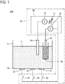
- FIG. 1 is a schematic diagram explaining the configuration of the hydrogel production apparatus.
- a hydrogel production apparatus 800 illustrated as an example includes an electrolytic tank 10, working electrodes 20, one counter electrode 30, one reference electrode 40, and a controller 85.
- the electrolytic tank 10 can house an electrolytic solution 11 and a hydrogel which is electrolytically deposited in the electrolytic solution 11.
- the working electrodes 20, the counter electrode 30, and the reference electrode 40 are attached in the electrolytic tank 10 in this example.
- the working electrodes 20 are arranged on a bottom surface 10a of the electrolytic tank 10 with predetermined pitches in the form of a two-dimensional array (example: a two-dimensional grid-like arrangement; a detailed illustration thereof is omitted in Fig. 1 ).
- the controller 85 applies a voltage between the counter electrode 30 and one or more selected working electrodes 20 selected from among the working electrodes 20.
- the controller 85 includes a potentiostat 50 and switches 60.
- a reference numeral 70 denotes a salt bridge.
- the counter electrode 30 and the reference electrode 40 are connected to the potentiostat 50.
- Each of the working electrodes 20 is connected to the potentiostat 50 via a corresponding one of the switches 60.
- the potentiostat 50 functions as a constant-voltage power supply device and is depicted as an equivalent circuit including a variable power source 51 and a voltmeter 52 (see Fig. 1 ). The application of a voltage between the counter electrode 30 and the working electrodes 20 is performed by the potentiostat 50.
- the basic circuit configuration of the potentiostat 50 is the same as the basic circuit configuration of a potentiostat which is used for common electrochemical measurement. That is, a potentiostat which is used for common electrochemical measurement can be used as part of the hydrogel production apparatus without any special change. For this reason, in the example of Fig. 1 , the potentiostat 50 includes an ammeter 53 like a potentiostat which is used for common electrochemical measurement.
- the controller 85 applies a predetermined voltage between the working electrode 20 selected by operation (ON/OFF) performed on the switch 60 and the one counter electrode 30.
- the hydrogel production apparatus 800 can further have a configuration which is useful for production of a hydrogel (a detailed illustration thereof is omitted in Fig. 1 ). This useful configuration will be described later.
- the transducer includes the hydrogel production apparatus and an integrated circuit.
- the bottom surface of the electrolytic tank is the front surface of the integrated circuit.
- the configuration of a transducer 900 will be described with reference to Fig. 2 .
- the transducer 900 has a configuration in which the electrolytic tank 10 covers an LSI chip 80.
- a hole 12 in the shape of a rectangle is formed in the center of the bottom of the electrolytic tank 10.
- the LSI chip 80 is disposed at the lower end of the hole 12 and closes the hole 12.
- the LSI chip 80 and the electrolytic tank 10 are fixed on a substrate 90.
- a large number of wiring patterns 91 for connection with an external device (which is not depicted in the drawing) which performs control of the LSI chip 80 are formed on the substrate 90.
- a reference numeral 92 denotes bonding wires that connect the LSI chip 80 and the wiring patterns 91.
- a shaping area 81 (a diagonally hatched portion in Fig. 2(a) ) for producing a hydrogel with a pattern is set on the upper surface of the LSI chip 80. Specifically, the shaping area 81 is set in the position of the hole 12 of the electrolytic tank 10 and faces the electrolytic solution 11. In the position of the hole 12, the shaping area 81 is part of the bottom surface 10a of the electrolytic tank 10.
- cells 82 are arranged in the shaping area 81 in the form of a two-dimensional grid array.
- One working electrode (a first electrode) 20 is formed in each cell 82 (see Figs. 2(c) and (d) ).
- 20 ⁇ 20 400 cells 82 are arranged with 250- ⁇ m pitches in the form of a two-dimensional grid array. That is, the LSI chip 80 has 400 working electrodes 20 arranged in the form of a two-dimensional grid array.
- the LSI chip 80 has a function of applying a voltage between the counter electrode 30 and each working electrode 20, a switching function, and so forth.
- the one counter electrode 30 and the one reference electrode 40 are installed in the electrolytic solution 11.
- the reference electrode 40 is located immediately above the shaping area 81, and the counter electrode 30 is located apart from the reference electrode 40 (see Fig. 2(b) ).
- the transducer 900 can further have a configuration which is useful for production of a hydrogel (a detailed illustration thereof is omitted in Fig. 2 ). This useful configuration will be described later.
- a method of electrochemically producing a hydrogel is classified into three types.
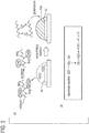
- Fig. 3 depicts how a hydrogel is produced by a cross-linking reaction, with chitosan being taken up as an example.
- hypochlorous acid H 2O
- a voltage is applied between the counter electrode (an electrode) 30 and the working electrode (an electrode) 20 in an aqueous solution in which chitosan and chlorine ions are present
- hypochlorous acid H 2O
- Chitosan is oxidized by hypochlorous acid (see Fig. 3(a) ).
- a cross-linking reaction occurs between the chitosan molecules, and a hydrogel 100, which is insoluble in a solvent, is deposited on the working electrode 20.
- the example is not limited to chitosan; for example, a hydrogel of gelatin or sodium alginate can also be produced based on a cross-linking reaction.
- a hydrogel of gelatin or sodium alginate can also be produced based on a cross-linking reaction.
- specific conditions of aqueous solutions in cases where chitosan is used and gelatin is used are as follows.
- a method of producing a hydrogel according to the present invention includes a process of producing a hydrogel by any one of reactions: 1) cross-linking between dispersoids, 2) electrostatic interaction, and 3) polymerization, which are started by an electrode reaction.
- the method of producing a hydrogel uses electrolytic deposition of a hydrogel by which a hydrogel is generated by a reaction induced, in an electrolytic solution, by an electrode product electrochemically generated by electrodes installed in the electrolytic solution.
- an electrolytic solution containing a precursor (i.e., dispersoids, charged polymers, monomers) of a hydrogel as a dissolved substance is housed in the electrolytic tank (a housing step) and, by applying a predetermined voltage between one or more selected working electrodes of the working electrodes arranged in the form of a two-dimensional array and the one counter electrode 30, a hydrogel with a two-dimensional pattern or a three-dimensional pattern corresponding to the arrangement of the selected working electrodes is produced (a production step).
- a precursor i.e., dispersoids, charged polymers, monomers
- a method of producing a hydrogel with a three-dimensional pattern includes a first step and a second step.
- a hydrogel with a first pattern is produced on the bottom surface of the electrolytic tank.
- the first working electrode group is made up of one or more selected working electrodes of the working electrodes 20.
- a hydrogel with a second pattern which is a two-dimensional pattern, is produced on the bottom surface of the electrolytic tank. Since the second pattern connects to the bottom surface of the first pattern, a hydrogel with a three-dimensional pattern as a whole is produced on the bottom surface of the electrolytic tank.
- the second working electrode group is made up of one or more selected working electrodes of the working electrodes 20. At least one working electrode included in the first working electrode group makes up the second working electrode group.
- a hydrogel with a three-dimensional pattern with a two-layer structure is produced.
- the hydrogel with the second pattern directly connects to the bottom surface (a surface, of the two surfaces perpendicular to a Z direction, closer to the bottom surface of the electrolytic tank) of the hydrogel with the first pattern.
- a three-dimensional pattern having a structure in which the first pattern is supported from below by the second pattern can be produced.
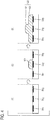
- Fig. 4 is a schematic diagram explaining a process of producing a hydrogel having a structure in which the first pattern is supported from below by the second pattern.
- a hydrogel 101 is produced on the working electrode 20 2 as depicted in Fig. 4(2) .
- a hydrogel 102 is produced on the working electrodes 20 1 , 20 2 , and 20 3 as depicted in Fig. 4(3) .
- a hydrogel 103 with a three-dimensional pattern having a structure in which the hydrogel 101 with the first pattern is supported from below by the hydrogel 102 with the second pattern is produced.
- Fig. 5 is a photograph of the actually produced hydrogel with a three-dimensional pattern. This hydrogel was produced by applying a voltage between the counter electrode 30 and the selected working electrodes 20 in a chitosan 1% (w/v) aqueous solution with the above-described conditions by using the transducer 900 depicted in Fig. 2 . Two voltage application modes (V1 mode, V2 mode) were started at the same time. V1 mode: 0 V, 20 s ⁇ 0.95 V, 10 s V2 mode: 0.95 V, 30 s
- a voltage in V1 mode was applied between the counter electrode 30 and the working electrodes 20 of the diagonally hatched cells 82 (see Fig. 2(c) ) and a voltage in V2 mode was applied between the counter electrode 30 and the working electrodes 20 of the cells 82 with a dot pattern (see Fig. 2(c) ).
- a voltage of 0.95 V was applied only between the counter electrode 30 and the working electrodes 20 of the cells 82 with a dot pattern for first 20 seconds and, for subsequent 10 seconds, a voltage of 0.95 V was applied between the counter electrode 30 and the working electrodes 20 of the diagonally hatched cells 82 and between the counter electrode 30 and the cells 82 with a dot pattern.
- a hydrogel with a three-dimensional pattern was produced in accordance with the arrangement of the selected working electrodes 20 and the voltage application mode (V1 mode, V2 mode).
- the constituent materials of the working electrodes 20, the counter electrode 30, and the reference electrode 40 of the transducer 900 are as follows.
- the second step is unnecessary because a hydrogel with a two-dimensional pattern is produced only by the first step.
- An embodiment is also admissible in which a step of discharging the electrolytic solution used in the first step from the electrolytic tank 10 and housing an electrolytic solution which is used in the second step in the electrolytic tank 10 is executed between the first step and the second step.
- the electrolytic solution which is used in the second step is different from the electrolytic solution used in the first step (at least one of the solvent and the dissolved substance of the electrolytic solution which is used in the second step is different from that of the electrolytic solution which is used in the first step).
- a hydrogel with a three-dimensional pattern with a layered structure such as the above-mentioned two-layer structure can be satisfactorily obtained by using a Z stage.
- the Z stage is a device that has an adhesion surface parallel to the bottom surface of the electrolytic tank and can move the adhesion surface in the Z direction perpendicular to the bottom surface of the electrolytic tank.
- a second embodiment of the hydrogel production apparatus includes the Z stage in addition to the configuration depicted in Fig. 1 .
- a second embodiment of the transducer includes the Z stage in addition to the configuration depicted in Fig. 2 .
- the Z stage included in the hydrogel production apparatus has a configuration in which the Z stage is independent of the hydrogel production apparatus or a configuration in which the Z stage is incorporated into the hydrogel production apparatus.
- the adhesion surface of the Z stage is disposed parallel to the bottom surface 10a of the electrolytic tank 10.
- the Z stage included in the transducer has a configuration in which the Z stage is independent of the transducer or a configuration in which the Z stage is incorporated into the transducer.
- the adhesion surface of the Z stage is disposed parallel to the shaping area 81.
- a part, which is immersed in the electrolytic solution, of the Z stage is preferably made of glass, for example, from the viewpoint of preventing deterioration caused by an electrochemical reaction.
- glass is a material having an affinity for water, it is preferable to perform additional treatment on the adhesion surface of the Z stage to enhance an affinity for water. Examples of this treatment include the application of polyethylene glycol, for instance.
- Fig. 6 is a schematic diagram depicting a process of producing the hydrogel depicted in Fig. 4 by using the Z stage.
- An adhesion surface 110a of a Z stage 110 is apart from the bottom surface 10a of the electrolytic tank by a first distance Z 1 in the electrolytic solution.
- the hydrogel 101 with the first pattern is formed on the working electrode 20 2 .
- the upper surface of the hydrogel 101 adheres to the adhesion surface 110a.
- the separation step in which the hydrogel 101 is separated from the working electrode 202 (see Fig. 6(3) ) will be described later in detail.
- the adhesion surface 110a of the Z stage 110 moves to a position apart from the bottom surface 10a of the electrolytic tank by a predetermined distance, which is longer than the first distance Z 1 , in the electrolytic solution with the hydrogel 101 adhering to the adhesion surface 110a of the Z stage 110.
- a lower surface 101a of the hydrogel 101 is apart from the bottom surface 10a of the electrolytic tank by a second distance Z 2 .
- a three-dimensional pattern having a structure in which the first pattern has the second pattern, which is smaller than the first pattern, hanging therefrom (in other words, when the bottom surface 10a of the electrolytic tank 10 or the shaping area 81 is viewed squarely, a structure in which: a) the whole of the second pattern is included in the first pattern; b) the area of the second pattern is smaller than the area of the first pattern; and c) the first pattern is on the second pattern) is satisfactorily produced. That is, a hydrogel with an inverted pyramid-shaped pattern is satisfactorily produced.
- the separation step is performed in a state in which the hydrogel 101 with the first pattern is in contact with the working electrode 202.
- a hydrogel separation voltage which is different from the voltage used in the production of the hydrogel 101, is applied between the counter electrode 30 and the working electrode 20 2 .
- the separation step allows the hydrogel 101 to move with the Z stage 110 while adhering to the adhesion surface 110a of the Z stage 110 (see Fig. 6(4) ).
- the separation step using the hydrogel separation voltage is useful when a sodium alginate solution, for instance, is used for production of a hydrogel.
- the reason is as follows: in the case of a sodium alginate solution, when a voltage which causes an oxidation reaction is applied between the counter electrode and the working electrode, an alginate hydrogel is deposited and, when a voltage which causes a reduction reaction is applied between the counter electrode and the working electrode, the alginate hydrogel is dissolved.
- the separation step using the hydrogel separation voltage is not an indispensable step. Easy separation of the hydrogel from the working electrode is made possible by, for example, reducing the contact area between the hydrogel and the bottom surface 10a of the electrolytic tank.
- all the working electrodes arranged in the form of a two-dimensional array protrude from the bottom surface of the electrolytic tank.
- the side faces of the working electrodes are surrounded with insulators protruding from the bottom surface of the electrolytic tank.
- Figs. 7A(1)-(3) are schematic diagrams depicting an example of a method of producing the working electrodes and the insulators which protrude from the bottom surface of the electrolytic tank.
- insulators 25 which form micro wells are produced on the working electrodes 20 by photolithography. Then, electrodes are produced by filling the insides of the micro wells with plating.
- Fig. 7A(3) working electrodes 20a which protrude from the bottom surface 10a of the electrolytic tank and have the side faces surrounded with the insulators 25 are produced.
- a hydrogel 104 produced by applying a voltage between the counter electrode 30 and the working electrodes 20a has a shape which does not make contact with the bottom surface 10a as depicted in Fig. 7B(2) .
- the hydrogel 104 is easily separated from the working electrodes 20a at the time of movement of the Z stage 110 depicted in Fig. 7B(3) .
- the bottom surface 10a which is rendered water-repellent, of the electrolytic tank.
- the bottom surface of the electrolytic tank other than the front surface of the working electrode is rendered water-repellent.
- Rendering the bottom surface water-repellent is, for example, coating the bottom surface with a thin film of fluorocarbon resin such as polytetrafluoroethylene (PTFE).
- the separation step using the hydrogel separation voltage can also be applied to other embodiments.
- At least one of the above-described first step and second step includes a first sub-step and a second sub-step.
- the first working electrode group includes a first sub-group and a second sub-group
- the first voltage includes a first sub-voltage and a second sub-voltage
- the first pattern includes a first sub-pattern and a second sub-pattern
- the second sub-group is made up of only the working electrode which does not belong to the first sub-group (in other words, the first sub-group and the second sub-group do not have a common working electrode).
- the second working electrode group includes a first sub-group and a second sub-group
- the second voltage includes a first sub-voltage and a second sub-voltage
- the second pattern includes a first sub-pattern and a second sub-pattern
- the second sub-group is made up of only the working electrode which does not belong to the first sub-group (in other words, the first sub-group and the second sub-group do not have a common working electrode).
- an electrode reaction in the first sub-step is an electrode reaction of oxidation and an electrode reaction in the second sub-step is an electrode reaction of reduction.
- a hydrogel In the case of sodium alginate, a hydrogel is produced by an oxidation reaction.
- a hydrogel In the case of sodium alginate, a hydrogel is produced by an oxidation reaction.
- a hydrogel In the case of chitosan, in accordance with pH adjustment, a hydrogel is produced by an oxidation reaction under certain pH conditions and a hydrogel is produced by a reduction reaction under other pH conditions.
- pH is set at conditions under which a chitosan hydrogel is produced by a reduction reaction, two types of hydrogel (a chitosan hydrogel and an alginate hydrogel) are produced in the first sub-step and the second sub-step.
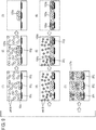
- Fig. 8 depicts an example in which each of the first step and the second step includes the first sub-step and the second sub-step.
- Fig. 8 is a schematic diagram explaining production of a hydrogel in which, in a hydrogel with a multi-layer structure, each layer is formed of two types of hydrogel and two types of hydrogel are alternately located in the thickness direction (the Z direction) of the hydrogel.
- a reference numeral 105 denotes an alginate hydrogel and a reference numeral 106 denotes a chitosan hydrogel.
- Fig. 8(2) depicts the first sub-step in the first step.
- the electrolytic tank 10 is filled with a sodium alginate solution.
- V s1 the first sub-voltage
- the alginate hydrogel 105 with the first sub-pattern is produced (the result of an oxidation reaction).
- the electrolytic tank 10 is filled with a chitosan solution.
- Fig. 8(3) depicts the second sub-step in the first step.
- the electrolytic tank 10 is filled with the chitosan solution.
- V s2 the second sub-voltage
- the chitosan hydrogel 106 with the second sub-pattern is produced (the result of a reduction reaction).
- the first sub-step in the second step is executed.
- the electrolytic tank 10 is filled with the chitosan solution.
- V s2 the first sub-voltage
- the chitosan hydrogel 106 with the first sub-pattern is produced (the result of a reduction reaction). That is, the chitosan hydrogel 106 is produced under the alginate hydrogel 105 depicted in Fig. 8(3) .
- the electrolytic tank 10 is filled with the sodium alginate solution.
- the second sub-step in the second step is executed.
- the electrolytic tank 10 is filled with the sodium alginate solution.
- V s1 the second sub-voltage
- the alginate hydrogel 105 with the second sub-pattern is produced (the result of an oxidation reaction). That is, the alginate hydrogel 105 is produced under the chitosan hydrogel 106 depicted in Fig. 8(3) .
- hydrogel 107 with a multi-layer structure (a four-layer structure in the example depicted in Fig. 8(4) ) is produced.
- an embodiment in which the above-described substeps are performed is permitted to have a modification including a sub-pattern removal step in which a selected hydrogel is removed.
- a hydrogel which is dissolved by predetermined treatment is produced in the second sub-step and, by performing the predetermined treatment after the first sub-step and the second sub-step, the hydrogel with the second sub-pattern is dissolved.
- degradation of the alginate hydrogel by the addition of an alginate degrading enzyme is used.
- the alginate degrading enzyme is diffused in the electrolytic solution.
- the second sub-pattern is selectively removed.
- the example is not limited to an enzyme; cross-linking scission by light irradiation, dissolution of gel by control of any one of pH and the temperature or both, and the like can also be used in the sub-pattern removal step.
- the first step includes the first sub-step and the second sub-step is also included in the embodiments of the present invention.
- a method of producing a hydrogel with a pattern formed of cells will be described.
- predetermined cells are distributed over a hydrogel which is a scaffold.
- a suspension containing a precursor of a hydrogel and predetermined cells is used as the electrolytic solution.
- this suspension it is possible to produce a hydrogel, in which the predetermined cells are dispersed, on the bottom surface of the electrolytic tank.
- the above-described method of producing a hydrogel is divided into the following four types.
- a suspension containing a precursor of a hydrogel and predetermined cells is used as the electrolytic solution which is used in the first step.
- a suspension containing a precursor of a hydrogel and one type of cell for example, is used as the electrolytic solution.
- the electrolytic solution which is used in the first sub-step and the electrolytic solution which is used in the second sub-step may be different from each other (at least one of the solvent and the dissolved substance of the electrolytic solution which is used in the first sub-step and that of the electrolytic solution which is used in the second sub-step are different from each other).
- a suspension containing a precursor X of a hydrogel and one type of cell Y1 is used as the electrolytic solution which is used in the first sub-step and a suspension containing the precursor X of a hydrogel and one type of cell Y2 (Y1 ⁇ Y2) is used as the electrolytic solution which is used in the second sub-step.
- a suspension containing a precursor of a hydrogel and one type of cell, for example, is used as the electrolytic solution.
- a hydrogel with the cells dispersed therein and with the first pattern and a hydrogel with the cells dispersed therein and with the second pattern or both is produced.
- the electrolytic solution which is used in the first step and the electrolytic solution which is used in the second step may be different from each other (at least one of the solvent and the dissolved substance of the electrolytic solution which is used in the first step and that of the electrolytic solution which is used in the second step are different from each other).
- a suspension containing a precursor X of a hydrogel and one type of cell Y1 is used as the electrolytic solution which is used in the first step
- a suspension containing the precursor X of a hydrogel and one type of cell Y2 (Y1 ⁇ Y2) is used as the electrolytic solution which is used in the second step.
- a suspension containing a hydrogel precursor and one type of cell, for example, is used as the electrolytic solution.
- the electrolytic solution which is used in the first sub-step and the electrolytic solution which is used in the second sub-step may be different from each other (at least one of the solvent and the dissolved substance of the electrolytic solution which is used in the first sub-step and that of the electrolytic solution which is used in the second sub-step are different from each other).
- Fig. 9 is a schematic diagram depicting a process of production of a multi-layer structure formed of an alginate hydrogel in which cells A are dispersed and a chitosan hydrogel in which cells B are dispersed.
- the electrolytic tank 10 is filled with a suspension containing sodium alginate and the cells A (see Fig. 9(1) ).
- Fig. 9(2) depicts the first sub-step in the first step.
- V s1 the first sub-voltage between the first sub-group (the working electrode 202) and the counter electrode 30
- an alginate hydrogel 105a with the first sub-pattern and with the cells A dispersed therein is produced (the result of an oxidation reaction).
- the electrolytic tank 10 After the suspension containing sodium alginate and the cells A is removed from the electrolytic tank 10 (see Fig. 9(3) ), the electrolytic tank 10 is filled with a suspension containing chitosan and the cells B (see Fig. 9(4) ).
- Fig. 9(5) depicts the second sub-step in the first step.
- the electrolytic tank 10 is filled with the suspension containing chitosan and the cells B.
- V s2 the second sub-voltage
- the second sub-group the working electrodes 20 1 and 20 3
- the counter electrode 30 By applying the second sub-voltage (V s2 ) between the second sub-group (the working electrodes 20 1 and 20 3 ) and the counter electrode 30, a chitosan hydrogel 106a with the second sub-pattern and with the cells B dispersed therein is produced (the result of a reduction reaction).
- the first sub-step in the second step is executed.
- the electrolytic tank 10 is filled with the suspension containing chitosan and the cells B.
- V s2 the first sub-voltage
- the chitosan hydrogel 106a with the first sub-pattern and with the cells B dispersed therein is produced (the result of a reduction reaction). That is, the chitosan hydrogel 106a is produced under the alginate hydrogel 105a depicted in Fig. 9(6) .
- the electrolytic tank 10 is filled with the suspension containing sodium alginate and the cells A.
- the second sub-step in the second step is executed.
- the electrolytic tank 10 is filled with the suspension containing sodium alginate and the cells A.
- V s1 the second sub-voltage
- the alginate hydrogel 105a with the second sub-pattern and with the cells A dispersed therein is produced (the result of an oxidation reaction). That is, the alginate hydrogel 105a is produced under the chitosan hydrogel 106a depicted in Fig. 9(6) .
- hydrogel 107a with a multi-layer structure (a three-layer structure in the example depicted in Fig. 9(7) ) is produced.
- predetermined cells are dispersed in a hydrogel in a structural arrangement with a three-dimensional design.
- the present invention is useful for producing a desired cell culture structure.
- An embodiment that produces a hydrogel in which predetermined cells are dispersed is permitted to have a modification including the above-described sub-pattern removal step.
- the above-described sub-pattern removal step is performed at the appropriate time in the process of producing a hydrogel in which predetermined cells are dispersed.
- the type of cell which is used in the present invention is not limited to a particular type.
- cells of any mammal induced pluripotent stem (iPS) cells, embryonic stem (ES) cells, mesenchymal stem cells, hepatocytes, vascular endothelial cells, fibroblasts, and the like are used.
- iPS induced pluripotent stem
- ES embryonic stem
- mesenchymal stem cells mesenchymal stem cells
- hepatocytes hepatocytes
- vascular endothelial cells fibroblasts, and the like
- vascular cells by disposing vascular cells in a predetermined area of a hydrogel, it is possible to produce a blood vessel having a predetermined shape.
- a dielectrophoresis step in a state in which a suspension is housed in the electrolytic tank.
- the dielectrophoresis step is performed before a step of producing a hydrogel by applying a predetermined voltage between the selected working electrode and the counter electrode.
- an alternating voltage of a predetermined frequency is applied between the selected working electrode and the counter electrode and cells are densely distributed on the selected working electrode by dielectrophoresis.
- the directivity of phoresis (an affinity of cells to the density of electrical flux lines) is controlled by a frequency.
- the working electrode and the counter electrode in the dielectrophoresis step serve as a positive electrode and a negative electrode which alternate by an alternating voltage.
- Fig. 10 is a schematic diagram depicting how dielectrophoresis of cells is performed.
- an electrode 120 with an electrode plane parallel to the bottom surface 10a of the electrolytic tank 10 is used.
- the electrode plane of the electrode 120 faces a region in which the two-dimensional array of the working electrodes 20 is formed.
- a reference numeral 130 denotes an oscillator that applies an alternating voltage of a predetermined frequency between the working electrode 20 and the electrode 120.
- a circle represents a cell and a dashed line represents an electrical flux line.
- an electrode formed on the bottom surface 10a may be used in place of the electrode 120.
- each working electrode 20 one electrode 121 for dielectrophoresis, which surrounds the working electrode 20, is formed on the bottom surface 10a (see Fig. 11(a) ).
- Each electrode 121 has a ring-like shape. The electrode 121 and the working electrode 20 are not in contact with each other.
- one plate electrode 122 for dielectrophoresis is formed on the bottom surface 10a (see Fig. 11(b) ). Holes corresponding to the positions of the working electrodes 20 are formed in the plate electrode 122. When the bottom surface 10a is viewed squarely, one working electrode 20 is located in one hole and the electrode 122 and the working electrode 20 are not in contact with each other.
- the hydrogel production apparatus 800 and the transducer 900 include the oscillator 130 in addition to the potentiostat 50.
- the electrode 120 for dielectrophoresis, the electrode 121 for dielectrophoresis, or the electrode 122 for dielectrophoresis is a constituent element of the hydrogel production apparatus 800 or the transducer 900 or is a part which can be attached to the hydrogel production apparatus 800 or the transducer 900.
- the electrode 120 does not interfere with the Z stage 110.
- the electrode 120 can be used as the counter electrode and the counter electrode 30 is unnecessary.
- the electrode 121 or the electrode 122 as a second electrode is formed in the shaping area 81 of the LSI chip 80. It is preferable to render a part of the shaping area 81 other than the front surface of the electrode water-repellent.
- Electrophoresis can also be used to concentrate the cells densely on the selected working electrode. Electrophoresis is performed by applying a predetermined direct voltage between the selected working electrode and the counter electrode. In an electrophoresis step which is performed on the negatively charged cells, the working electrode serves as a positive electrode and the counter electrode serves as a negative electrode.
- a method of electrochemically producing a hydrogel by using electrolytic deposition including:
- the electrochemical production method described in Item 2 including, between the first step and the second step, a step of discharging the electrolytic solution used in the first step from the electrolytic tank and housing, in the electrolytic tank, the electrolytic solution which is to be used in the second step, wherein the electrolytic solution used in the second step is different from the electrolytic solution used in the first step.
- first step and the second step include a first sub-step and a second sub-step
- first working electrode group includes a first sub-group and a second sub-group
- the first voltage includes a first sub-voltage and a second sub-voltage
- the first pattern includes a first sub-pattern and a second sub-pattern
- the first sub-group and the second sub-group do not have a common working electrode
- the second working electrode group includes a first sub-group and a second sub-group
- the second voltage includes a first sub-voltage and a second sub-voltage
- the second pattern includes a first sub-pattern and a second sub-pattern
- the first sub-group and the second sub-group do not have a common working electrode
- the electrochemical production method described in Item 4 including, between the first sub-step and the second sub-step, a step of discharging the electrolytic solution used in the first sub-step from the electrolytic tank and housing, in the electrolytic tank, the electrolytic solution which is to be used in the second sub-step, wherein the electrolytic solution used in the second sub-step is different from the electrolytic solution used in the first sub-step.
- a method of producing a hydrogel with a pattern formed of cells including a step of using an electrochemical production method that is the electrochemical production method described in any one of Items 1 to 13 and uses, as an electrolytic solution, a suspension containing a precursor of the hydrogel and the cells.
- a hydrogel production apparatus for producing a hydrogel by using electrolytic deposition including:
- each of the working electrodes protrudes from the bottom surface, and wherein side faces of the working electrodes are surrounded with insulators protruding from the bottom surface of the electrolytic tank.
- a hydrogel production apparatus for producing a hydrogel by using electrolytic deposition including:
- hydrogel production apparatus described in any one of Items 16 to 19, further including:
- a transducer including:
- the technique of producing a hydrogel according to the present invention is useful in, for example, assessment of drugs as an alternative to animal testing, production of operation practice equipment, production of medical supplies, and so forth.
Landscapes
- Chemical & Material Sciences (AREA)
- Organic Chemistry (AREA)
- Engineering & Computer Science (AREA)
- Health & Medical Sciences (AREA)
- Chemical Kinetics & Catalysis (AREA)
- Life Sciences & Earth Sciences (AREA)
- Materials Engineering (AREA)
- Electrochemistry (AREA)
- Metallurgy (AREA)
- Bioinformatics & Cheminformatics (AREA)
- Zoology (AREA)
- Wood Science & Technology (AREA)
- Genetics & Genomics (AREA)
- Biochemistry (AREA)
- General Health & Medical Sciences (AREA)
- Biotechnology (AREA)
- Biomedical Technology (AREA)
- General Engineering & Computer Science (AREA)
- Microbiology (AREA)
- Immunology (AREA)
- Sustainable Development (AREA)
- Dispersion Chemistry (AREA)
- Molecular Biology (AREA)
- Analytical Chemistry (AREA)
- Manufacturing & Machinery (AREA)
- Crystallography & Structural Chemistry (AREA)
- Pathology (AREA)
- Medicinal Chemistry (AREA)
- General Physics & Mathematics (AREA)
- Physics & Mathematics (AREA)
- Apparatus Associated With Microorganisms And Enzymes (AREA)
- Colloid Chemistry (AREA)
- Physical Or Chemical Processes And Apparatus (AREA)
- Micro-Organisms Or Cultivation Processes Thereof (AREA)
- Immobilizing And Processing Of Enzymes And Microorganisms (AREA)
- Electrolytic Production Of Non-Metals, Compounds, Apparatuses Therefor (AREA)
Abstract
Description
- The present invention relates to a method of electrochemically producing a hydrogel by using electrolytic deposition, a method of producing a hydrogel with a pattern formed of cells, a hydrogel production apparatus, and a transducer.
- A hydrogel is used as a scaffold for cell culture, for example. A method of electrochemically producing a hydrogel by using electrolytic deposition is known.
-
Non-patent Literature 1 and Non-patentLiterature 2 disclose methods of electrolytically depositing, on an indium tin oxide (ITO) electrode with a pattern, a hydrogel corresponding to the pattern.Non-patent Literature 3 and Non-patentLiterature 4 disclose methods of electrolytically depositing a hydrogel by using a Pt wire electrode or by making a Pt wire electrode perform scanning in an electrolytic solution.Non-patent Literature 5 and Non-patentLiterature 6 disclose techniques of electrolytically depositing a hydrogel or the like, by applying a voltage to one electrode selected from two electrodes or from among one-dimensional array of electrodes or, on the electrode. -
- Non-patent Literature 1: F. Ozawa et al., "Cell Sheet Fabrication Using RGD Peptide-Coupled Alginate Hydrogels Fabricated by an Electrodeposition Method", Chemistry Letters, Vol. 46, No. 4, pp 605-608, Advance Publication on the web February 10, 2017. <http://www.journal.csj.jp/doi/pdf/10.1246/cl.170003>
- Non-patent Literature 2: F. Ozawa et al., "Alginate gel microwell arrays using electrodepotion for three-dimensional cell culture", Lab on a Chip, 2013, 13(15), pp 3128-3135. <http://pubs.rsc.org/en/Content/ArticleLanding/2013/LC/c31c50455g#!div Abstract>
- Non-patent Literature 3: F. Ozawa et al., "Electrochemical Hydrogel Lithography of Calcium-Alginate Hydrogels for Cell Culture", Materials, 2016, 9(9), 744. <http://www.mdpi.com/1996-1944/9/9/744>
- Non-patent Literature 4: F. Ozawa et al., "Electrodeposition of alginate gels for construction of vascular-like structures", Journal of Bioscience and Bioengineering, 2013, VOL 115, No. 4, pp 459-461. <http://www.sciencedirect.com/science/article/pii/S1389172312004409?via %3Dihub>
- Non-patent Literature 5: K. M. Gray et al., "Electrodeposition of a Biopolymeric Hydrogel: Potential for One-Step Protein Electroaddressing", Biomacromolecules, 2012, 13(4), pp 1181-1189. <http://pubs.acs.org/doi/abs/10.1021/bm3001155>
- Non-patent Literature 6: H. Yi et al., "Signal-Directed sequential Assembly of Biomolecules on Patterned surfaces", Langmuir, 2005, 21(6), pp 2104-2107. <http://pubs.acs.org/doi/abs/10.1021/la047529k>
- Non-patent
Literatures 1 to 6 disclose the methods of electrolytically depositing a hydrogel. However, with the methods disclosed inNon-patent Literatures Non-patent Literatures Non-patent Literatures Non-patent Literatures - The present invention provides a technique of electrochemically producing a hydrogel, the technique that has a higher degree of flexibility in shaping, has greater versatility, and can form a hydrogel with a two-dimensional pattern or a three-dimensional pattern more efficiently than ever before.
- According to an invention of
Claim 1, a method of electrochemically producing a hydrogel by using electrolytic deposition of a hydrogel, the method by which a hydrogel is formed by a reaction which is induced in an electrolytic solution by an electrode product electrochemically generated by electrodes installed in the electrolytic solution, includes a step of preparing an apparatus including an electrolytic tank with a bottom surface on which a two-dimensional array of working electrodes is provided and a counter electrode which is installed in the electrolytic tank, housing an electrolytic solution containing a dissolved substance, which causes electrolytic deposition of the hydrogel, in the electrolytic tank, and, by applying a predetermined voltage to one or more selected working electrodes of the two-dimensional array of the working electrodes, forming, on the bottom surface, the hydrogel with a two-dimensionally defined pattern corresponding to the arrangement of the selected working electrodes. - In an invention of
Claim 2, the invention ofClaim 1 includes: a first step of forming a hydrogel with a two-dimensionally defined first pattern by applying a first voltage as the predetermined voltage to a first working electrode group as the one or more selected working electrodes; and a second step of forming a hydrogel with a two-dimensionally defined second pattern by applying a second voltage as the predetermined voltage to a second working electrode group as the one or more selected working electrodes. The second step is performed after the first step, and a hydrogel with a three-dimensionally defined pattern including at least two layers formed of the first pattern and the second pattern, which is located under the first pattern on the side thereof closer to the bottom surface, is formed. - In an invention of
Claim 3, in the invention ofClaim 2, at least one of the first step and the second step includes a first sub-step and a second sub-step, a corresponding one of the first working electrode group and the second working electrode group includes a first working electrode sub-group and a second working electrode sub-group, a corresponding one of the first voltage and the second voltage includes a first sub-voltage and a second sub-voltage, and a corresponding one of the first pattern and the second pattern incudes a first sub-pattern and a second sub-pattern. The second working electrode sub-group consists of only the working electrode which does not belong to the first working electrode sub-group. A hydrogel with the first sub-pattern is formed by applying the first sub-voltage to the first working electrode sub-group and a hydrogel with the second sub-pattern is formed by applying the second sub-voltage to the second working electrode sub-group. - In an invention of
Claim 4, in the invention ofClaim 3, in the second sub-step, a hydrogel which dissolves under a predetermined condition is formed. The invention ofClaim 3 further includes, at least after the first sub-step and the second sub-step, a sub-pattern removal step of selectively removing the hydrogel with the second sub-pattern by dissolving the hydrogel with the second sub-pattern by providing the hydrogel with the second sub-pattern with the predetermined condition. - In an invention of
Claim 5, in the invention of any one ofClaims 2 to 4, a Z stage that has an adhesion surface facing the bottom surface parallel thereto and is displaceable in a Z direction perpendicular to the bottom surface is further prepared. By performing the first step with the Z stage being located in the electrolytic solution such that the adhesion surface is apart from the bottom surface by a first distance, a hydrogel with the first pattern whose upper surface, of two surfaces perpendicular to the Z direction, on the side farther apart from the bottom surface adheres to the adhesion surface is formed. After that, by displacing the Z stage with the adhesion surface, to which the upper surface of the first pattern adheres, in a direction in which the Z stage moves away from the bottom surface, a lower surface, of the two surfaces perpendicular to the Z direction, of the first pattern on the side closer to the bottom surface is moved away from the bottom surface by a second distance. By performing the second step with the first pattern being located in the electrolytic solution such that the lower surface is apart from the bottom surface by the second distance, a hydrogel with the second pattern connecting to the lower surface of the first pattern is formed. - In an invention of
Claim 6, in the invention ofClaim 5, the adhesion surface is subjected to treatment that makes the adhesion surface have an affinity for water. - In an invention of
Claim 7, in the invention of any one ofClaims 2 to 6, all of the first working electrode groups are included in the second working electrode group and the three-dimensionally defined pattern has a structure in which the first pattern is supported from below by the second pattern. - In an invention of Claim 8, in the invention of
Claim - In an invention of Claim 9, in the invention of any one of
Claims 1 to 8, all of the working electrodes which compose the two-dimensional array protrude from the bottom surface and side faces of each protruding working electrode are surrounded with an insulating layer formed so as to protrude from the bottom surface along with the working electrode. - In an invention of
Claim 10, in the invention of any one ofClaims 1 to 9, a part of the bottom surface other than front surfaces of the working electrodes is made water-repellent. - In an invention of
Claim 11, the invention of any one ofClaims 1 to 10 further includes a step of forming, on the bottom surface, a hydrogel with the two-dimensionally defined pattern corresponding to the arrangement of the selected working electrodes by applying the predetermined voltage to the selected working electrodes, and after that, in a state in which the formed hydrogel is in contact with the selected working electrodes, promoting separation of the hydrogel from the selected working electrodes by dissolving a contact part of the hydrogel with the selected working electrodes by applying a voltage for hydrogel separation, which is different from the predetermined voltage, to the selected working electrodes. - According to an invention of
Claim 12, in a method of producing a hydrogel patterned with cells, which is obtained by distributing predetermined cells over a hydrogel scaffold, by performing the invention of any one ofClaims 1 to 11 by using, as an electrolytic solution containing a dissolved substance which causes electrolytic deposition of the hydrogel, a suspension further containing the predetermined cells, a hydrogel with the distributed predetermined cells is formed on the bottom surface of the electrolytic tank. - In an invention of Claim 13, in the invention of
Claim 12, the predetermined cells include one or more types of cells. The invention ofClaim 12 includes a step of performing the invention ofClaim 2 by using, as the electrolytic solution, a suspension containing one type of cell of the predetermined cells along with a dissolved substance, which causes electrolytic deposition of the hydrogel, in any one of the first step and the second step. - In an invention of Claim 14, the invention of Claim 13 includes a step of performing the method by using, as the electrolytic solution, a suspension containing the other type of cell, which is different from the one type of cell, of the predetermined cells along with a dissolved substance, which causes electrolytic deposition of the hydrogel, in the other of the first step and the second step.
- In an invention of Claim 15, in the invention of
Claim 12, the predetermined cells include one or more types of cells, and the invention ofClaim 3 is performed by using, as the electrolytic solution, a suspension containing one type of cell of the predetermined cells along with a dissolved substance, which causes electrolytic deposition of the hydrogel, in any one of the first sub-step and the second sub-step. - In an invention of Claim 16, in the invention of Claim 15, the method is performed by using, as the electrolytic solution, a suspension containing the other type of cell, which is different from the one type of cell, of the predetermined cells along with a dissolved substance, which causes electrolytic deposition of the hydrogel, in the other of the first sub-step and the second sub-step.
- In an invention of Claim 17, the invention of any one of
Claims 12 to 16 includes, before a step of forming a hydrogel by applying the predetermined voltage to the selected working electrodes in a state in which the suspension is housed in the electrolytic tank, a dielectrophoresis step of densely distributing the predetermined cells on the selected working electrodes by dielectrophoresis by applying an alternating voltage of a predetermined frequency to the selected working electrodes. - In an invention of Claim 18, in the invention of Claim 17, in the dielectrophoresis step, an electrode with an electrode plane facing, parallel to the bottom surface, a region of the bottom surface in which the two-dimensional array of the working electrodes is provided is used.
- In an invention of Claim 19, in the invention of Claim 17, in the dielectrophoresis step, an electrode which is provided on the bottom surface so as to be located around each of the two-dimensional array of the working electrodes is used.
- In an invention of
Claim 20, the invention of any one ofClaims 12 to 16 includes, before a step of forming a hydrogel by applying the predetermined voltage to the selected working electrodes in a state in which the suspension is housed in the electrolytic tank, an electrophoresis step of densely distributing the predetermined cells on the selected working electrodes by electrophoresis by applying a predetermined direct voltage to the selected working electrodes. - According to an invention of Claim 21, a hydrogel production apparatus that includes an electrolytic tank with a bottom surface on which a two-dimensional array of working electrodes is provided and a counter electrode, which is installed in the electrolytic tank, and can apply a predetermined voltage to one or more selected working electrodes of the two-dimensional array of the working electrodes includes a Z stage that has an adhesion surface facing the bottom surface parallel thereto and is displaceable in a Z direction perpendicular to the bottom surface.
- In an invention of
Claim 22, in the invention of Claim 21, the adhesion surface is subjected to treatment that makes the adhesion surface have an affinity for water. - According to an invention of Claim 23, in a hydrogel production apparatus that includes an electrolytic tank with a bottom surface on which a two-dimensional array of working electrodes is provided and a counter electrode, which is installed in the electrolytic tank, and can apply a predetermined voltage to one or more selected working electrodes of the two-dimensional array of the working electrodes, all of the working electrodes that make up the two-dimensional array protrude from the bottom surface and side faces of each protruding working electrode are surrounded with an insulating layer formed so as to protrude from the bottom surface along with the working electrode.
- In an invention of Claim 24, in the invention of
Claim 21 or 22, all of the working electrodes that make up the two-dimensional array protrude from the bottom surface and side faces of each protruding working electrode are surrounded with an insulating layer formed so as to protrude from the bottom surface along with the working electrode. - In an invention of
Claim 25, in the invention of any one of Claims 21 to 24, a part of the bottom surface other than front surfaces of the working electrodes is made water-repellent. - In an invention of Claim 26, the invention of any one of Claims 21 to 25 includes an oscillator that can apply an alternating voltage of a predetermined frequency to the selected working electrodes.
- In an invention of Claim 27, the invention of Claim 26 further includes an electrode for dielectrophoresis that is installed or can be installed in the electrolytic tank, and the electrode for dielectrophoresis is installed or can be installed in the electrolytic tank so that an electrode plane thereof faces, parallel to the bottom surface, a region of the bottom surface in which the two-dimensional array of the working electrodes is provided.
- In an invention of Claim 28, in the invention of Claim 26, the electrolytic tank further includes an electrode for dielectrophoresis and the electrode for dielectrophoresis is provided on the bottom surface so as to be located around each of the two-dimensional array of the working electrodes.
- According to an invention of Claim 29, in a transducer that includes an electrolytic tank, which can house an electrolytic solution and a hydrogel which is electrolytically deposited in the electrolytic solution, mounted on an LSI chip and is used for electrochemical production of a patterned hydrogel, in a shaping area defined on a bottom surface of the electrolytic tank, first electrodes which are provided in the LSI chip in a two-dimensional array arrangement are located. The transducer includes a Z stage with an adhesion surface, which can be installed in the electrolytic tank. The Z stage can be installed in the electrolytic tank so as be displaceable in a Z direction perpendicular to the bottom surface, in such a way that the adhesion surface faces the shaping area of the bottom surface parallel to the shaping area.
- In an invention of
Claim 30, in the invention of Claim 29, the adhesion surface is subjected to treatment that makes the adhesion surface have an affinity for water. - According to an invention of Claim 31, in a transducer that includes an electrolytic tank, which can house an electrolytic solution and a hydrogel which is electrolytically deposited in the electrolytic solution, mounted on an LSI chip and is used for electrochemical production of a patterned hydrogel, in a shaping area defined on a bottom surface of the electrolytic tank, first electrodes which are provided in the LSI chip in a two-dimensional array arrangement are located, and all of the first electrodes protrude from the bottom surface and side faces of each protruding first electrode are surrounded with an insulating layer formed so as to protrude from the bottom surface along with the first electrode.
- In an invention of Claim 32, in the invention of any one of Claims 29 to 31, a part of the shaping area other than front surfaces of the first electrodes is made water-repellent.
- In an invention of Claim 33, in the invention of any one of Claims 29 to 31, in the shaping area, a second electrode which is provided in the LSI chip so as to be located around each of the first electrodes is further located.
- In an invention of Claim 34, in the invention of Claim 33, the second electrode is formed over the entire surface of the shaping area without continuity between the first electrodes and the second electrode.
- In an invention of Claim 35, in the invention of Claim 33 or 34, a part of the shaping area other than front surfaces of the first electrodes and a front surface of the second electrode is made water-repellent.
- In an invention of Claim 36, the invention of any one of Claims 29 to 32 further includes a second electrode that is installed or can be installed in the electrolytic tank, and the second electrode is installed or can be installed in the electrolytic tank so that an electrode plane thereof faces the shaping area of the bottom surface parallel to the shaping area.
- According to the present invention, it is possible to achieve a higher degree of flexibility in shaping, achieve greater versatility, and form a hydrogel with a two-dimensional pattern or a three-dimensional pattern more efficiently than ever before.
-
-
Fig. 1 is a diagram for explaining the configuration of a hydrogel production apparatus of an embodiment. -
Fig. 2 is a diagram for explaining the configuration of a transducer of an embodiment: (a) a plan view; (b) a sectional view; (c) a diagram depicting the arrangement of cells of an LSI chip; and (d) a diagram depicting a working electrode provided in each cell. -
Fig. 3 is a diagram for explaining electrochemical hydrogel production. -
Fig. 4 is a diagram for explaining a method of electrochemically producing a hydrogel (an embodiment). -
Fig. 5 is a photograph of a hydrogel actually produced by the method of electrochemically producing a hydrogel (an embodiment). -
Fig. 6 is a diagram for explaining the method of electrochemically producing a hydrogel (an embodiment). -
Fig. 7A is a diagram for explaining a method of forming the working electrode protruding from a bottom surface of an electrolytic tank. -
Fig. 7B is a diagram for explaining the formation and separation of a hydrogel which are performed when the working electrode depicted inFig. 7A is used. -
Fig. 8 is a diagram for explaining the method of electrochemically producing a hydrogel (an embodiment). -
Fig. 9 is a diagram for explaining a method of producing a hydrogel with a pattern formed of cells (an embodiment). -
Fig. 10 is a diagram for explaining dielectrophoresis which is performed to concentrate cells on the working electrode. -
Fig. 11 is a diagram depicting an example of an electrode for dielectrophoresis: (a) an example of an annular electrode; and (b) an example of a solid electrode. - The principles and embodiments of a technique of electrochemically producing a hydrogel according to the present invention will be described with reference to the drawings.
- First, the configuration of a hydrogel production apparatus will be described; then, the configuration of a transducer will be described.
-
Fig. 1 is a schematic diagram explaining the configuration of the hydrogel production apparatus. Ahydrogel production apparatus 800 illustrated as an example includes anelectrolytic tank 10, workingelectrodes 20, onecounter electrode 30, onereference electrode 40, and acontroller 85. Theelectrolytic tank 10 can house anelectrolytic solution 11 and a hydrogel which is electrolytically deposited in theelectrolytic solution 11. The workingelectrodes 20, thecounter electrode 30, and thereference electrode 40 are attached in theelectrolytic tank 10 in this example. The workingelectrodes 20 are arranged on abottom surface 10a of theelectrolytic tank 10 with predetermined pitches in the form of a two-dimensional array (example: a two-dimensional grid-like arrangement; a detailed illustration thereof is omitted inFig. 1 ). Thecontroller 85 applies a voltage between thecounter electrode 30 and one or more selected workingelectrodes 20 selected from among the workingelectrodes 20. Thecontroller 85 includes apotentiostat 50 and switches 60. InFig. 1 , areference numeral 70 denotes a salt bridge. - The
counter electrode 30 and thereference electrode 40 are connected to thepotentiostat 50. Each of the workingelectrodes 20 is connected to thepotentiostat 50 via a corresponding one of theswitches 60. The potentiostat 50 functions as a constant-voltage power supply device and is depicted as an equivalent circuit including avariable power source 51 and a voltmeter 52 (seeFig. 1 ). The application of a voltage between thecounter electrode 30 and the workingelectrodes 20 is performed by thepotentiostat 50. - The basic circuit configuration of the
potentiostat 50 is the same as the basic circuit configuration of a potentiostat which is used for common electrochemical measurement. That is, a potentiostat which is used for common electrochemical measurement can be used as part of the hydrogel production apparatus without any special change. For this reason, in the example ofFig. 1 , thepotentiostat 50 includes anammeter 53 like a potentiostat which is used for common electrochemical measurement. - The
controller 85 applies a predetermined voltage between the workingelectrode 20 selected by operation (ON/OFF) performed on theswitch 60 and the onecounter electrode 30. Thehydrogel production apparatus 800 can further have a configuration which is useful for production of a hydrogel (a detailed illustration thereof is omitted inFig. 1 ). This useful configuration will be described later. - Next, the transducer will be described. The transducer includes the hydrogel production apparatus and an integrated circuit. The bottom surface of the electrolytic tank is the front surface of the integrated circuit. The configuration of a
transducer 900 will be described with reference toFig. 2 . - The
transducer 900 has a configuration in which theelectrolytic tank 10 covers anLSI chip 80. Ahole 12 in the shape of a rectangle is formed in the center of the bottom of theelectrolytic tank 10. TheLSI chip 80 is disposed at the lower end of thehole 12 and closes thehole 12. - The
LSI chip 80 and theelectrolytic tank 10 are fixed on asubstrate 90. A large number ofwiring patterns 91 for connection with an external device (which is not depicted in the drawing) which performs control of theLSI chip 80 are formed on thesubstrate 90. InFig. 2(b) , areference numeral 92 denotes bonding wires that connect theLSI chip 80 and thewiring patterns 91. - A shaping area 81 (a diagonally hatched portion in
Fig. 2(a) ) for producing a hydrogel with a pattern is set on the upper surface of theLSI chip 80. Specifically, the shapingarea 81 is set in the position of thehole 12 of theelectrolytic tank 10 and faces theelectrolytic solution 11. In the position of thehole 12, the shapingarea 81 is part of thebottom surface 10a of theelectrolytic tank 10. - In this example, as depicted in
Fig. 2(c) ,cells 82 are arranged in the shapingarea 81 in the form of a two-dimensional grid array. One working electrode (a first electrode) 20 is formed in each cell 82 (seeFigs. 2(c) and (d) ). In this example, 20 × 20 = 400cells 82 are arranged with 250-µm pitches in the form of a two-dimensional grid array. That is, theLSI chip 80 has 400 workingelectrodes 20 arranged in the form of a two-dimensional grid array. - The
LSI chip 80 has a function of applying a voltage between thecounter electrode 30 and each workingelectrode 20, a switching function, and so forth. The onecounter electrode 30 and the onereference electrode 40 are installed in theelectrolytic solution 11. Thereference electrode 40 is located immediately above the shapingarea 81, and thecounter electrode 30 is located apart from the reference electrode 40 (seeFig. 2(b) ). Thetransducer 900 can further have a configuration which is useful for production of a hydrogel (a detailed illustration thereof is omitted inFig. 2 ). This useful configuration will be described later. - Here, the principles of production of a hydrogel by an electrochemical method will be described.
- A method of electrochemically producing a hydrogel is classified into three types.
- 1) Gelation of dispersoids caused by cross-linking
- 2) Cohesion of charged polymers caused by electrostatic interaction
- 3) Transformation of monomers into polymers by polymerization
-
Fig. 3 depicts how a hydrogel is produced by a cross-linking reaction, with chitosan being taken up as an example. When a voltage is applied between the counter electrode (an electrode) 30 and the working electrode (an electrode) 20 in an aqueous solution in which chitosan and chlorine ions are present, hypochlorous acid (HClO) is generated by an electrode reaction (seeFig. 3(b) ). Chitosan is oxidized by hypochlorous acid (seeFig. 3(a) ). Then, a cross-linking reaction occurs between the chitosan molecules, and ahydrogel 100, which is insoluble in a solvent, is deposited on the workingelectrode 20. - The example is not limited to chitosan; for example, a hydrogel of gelatin or sodium alginate can also be produced based on a cross-linking reaction. Examples of specific conditions of aqueous solutions in cases where chitosan is used and gelatin is used are as follows.
- chitosan: 1% (w/v) solution (0.15 M NaCl, adjusted by acetic acid so as to be pH 5.5)
- gelatin: 10% (w/v) solution (4 M NaCl, 10 mM acetate buffer adjusted so as to be pH 5.6)
- A method of producing a hydrogel according to the present invention includes a process of producing a hydrogel by any one of reactions: 1) cross-linking between dispersoids, 2) electrostatic interaction, and 3) polymerization, which are started by an electrode reaction. The method of producing a hydrogel uses electrolytic deposition of a hydrogel by which a hydrogel is generated by a reaction induced, in an electrolytic solution, by an electrode product electrochemically generated by electrodes installed in the electrolytic solution.
- According to an embodiment of the present invention, in the
hydrogel production apparatus 800 and thetransducer 900, an electrolytic solution containing a precursor (i.e., dispersoids, charged polymers, monomers) of a hydrogel as a dissolved substance is housed in the electrolytic tank (a housing step) and, by applying a predetermined voltage between one or more selected working electrodes of the working electrodes arranged in the form of a two-dimensional array and the onecounter electrode 30, a hydrogel with a two-dimensional pattern or a three-dimensional pattern corresponding to the arrangement of the selected working electrodes is produced (a production step). - A method of producing a hydrogel with a three-dimensional pattern includes a first step and a second step.
- By applying a first voltage, which is a predetermined voltage, between all the working electrodes included in a first working electrode group and one counter electrode, a hydrogel with a first pattern, which is a two-dimensional pattern, is produced on the bottom surface of the electrolytic tank. The first working electrode group is made up of one or more selected working electrodes of the working
electrodes 20. - By applying a second voltage, which is a predetermined voltage, between all the working electrodes included in a second working electrode group and one counter electrode, a hydrogel with a second pattern, which is a two-dimensional pattern, is produced on the bottom surface of the electrolytic tank. Since the second pattern connects to the bottom surface of the first pattern, a hydrogel with a three-dimensional pattern as a whole is produced on the bottom surface of the electrolytic tank. The second working electrode group is made up of one or more selected working electrodes of the working
electrodes 20. At least one working electrode included in the first working electrode group makes up the second working electrode group. - By performing the second step after the first step, a hydrogel with a three-dimensional pattern with a two-layer structure is produced. In the hydrogel with a three-dimensional pattern with a two-layer structure, the hydrogel with the second pattern directly connects to the bottom surface (a surface, of the two surfaces perpendicular to a Z direction, closer to the bottom surface of the electrolytic tank) of the hydrogel with the first pattern.
- When all the working electrodes included in the first working electrode group are included in the second working electrode group, a three-dimensional pattern having a structure in which the first pattern is supported from below by the second pattern can be produced.
-
Fig. 4 is a schematic diagram explaining a process of producing a hydrogel having a structure in which the first pattern is supported from below by the second pattern. When a voltage is applied between thecounter electrode 30 and a workingelectrode 202, ahydrogel 101 is produced on the workingelectrode 202 as depicted inFig. 4(2) . Next, when a voltage is applied between thecounter electrode 30 and workingelectrodes hydrogel 102 is produced on the workingelectrodes Fig. 4(3) . As a result, ahydrogel 103 with a three-dimensional pattern having a structure in which thehydrogel 101 with the first pattern is supported from below by thehydrogel 102 with the second pattern is produced. -
Fig. 5 is a photograph of the actually produced hydrogel with a three-dimensional pattern. This hydrogel was produced by applying a voltage between thecounter electrode 30 and the selected workingelectrodes 20 in achitosan 1% (w/v) aqueous solution with the above-described conditions by using thetransducer 900 depicted inFig. 2 . Two voltage application modes (V1 mode, V2 mode) were started at the same time.
V1 mode: 0 V, 20 s → 0.95 V, 10 s
V2 mode: 0.95 V, 30 s - Specifically, a voltage in V1 mode was applied between the
counter electrode 30 and the workingelectrodes 20 of the diagonally hatched cells 82 (seeFig. 2(c) ) and a voltage in V2 mode was applied between thecounter electrode 30 and the workingelectrodes 20 of thecells 82 with a dot pattern (seeFig. 2(c) ). In other words, a voltage of 0.95 V was applied only between thecounter electrode 30 and the workingelectrodes 20 of thecells 82 with a dot pattern for first 20 seconds and, for subsequent 10 seconds, a voltage of 0.95 V was applied between thecounter electrode 30 and the workingelectrodes 20 of the diagonally hatchedcells 82 and between thecounter electrode 30 and thecells 82 with a dot pattern. - It is understood from
Fig. 5 that a hydrogel with a three-dimensional pattern was produced in accordance with the arrangement of the selected workingelectrodes 20 and the voltage application mode (V1 mode, V2 mode). In this experiment, the constituent materials of the workingelectrodes 20, thecounter electrode 30, and thereference electrode 40 of thetransducer 900 are as follows.
The working electrodes 20: Au
The counter electrode 30: Pt
The reference electrode 40: Ag/AgCl - When a hydrogel with a two-dimensional pattern is produced, the second step is unnecessary because a hydrogel with a two-dimensional pattern is produced only by the first step.
- An embodiment is also admissible in which a step of discharging the electrolytic solution used in the first step from the
electrolytic tank 10 and housing an electrolytic solution which is used in the second step in theelectrolytic tank 10 is executed between the first step and the second step. In this case, preferably, the electrolytic solution which is used in the second step is different from the electrolytic solution used in the first step (at least one of the solvent and the dissolved substance of the electrolytic solution which is used in the second step is different from that of the electrolytic solution which is used in the first step). According to such an embodiment, it is possible to produce a hydrogel with a three-dimensional pattern with an alginate hydrogel on a chitosan hydrogel, for example. - A hydrogel with a three-dimensional pattern with a layered structure such as the above-mentioned two-layer structure can be satisfactorily obtained by using a Z stage. The Z stage is a device that has an adhesion surface parallel to the bottom surface of the electrolytic tank and can move the adhesion surface in the Z direction perpendicular to the bottom surface of the electrolytic tank.
- A second embodiment of the hydrogel production apparatus includes the Z stage in addition to the configuration depicted in
Fig. 1 . A second embodiment of the transducer includes the Z stage in addition to the configuration depicted inFig. 2 . The Z stage included in the hydrogel production apparatus has a configuration in which the Z stage is independent of the hydrogel production apparatus or a configuration in which the Z stage is incorporated into the hydrogel production apparatus. In the hydrogel production apparatus, the adhesion surface of the Z stage is disposed parallel to thebottom surface 10a of theelectrolytic tank 10. Likewise, the Z stage included in the transducer has a configuration in which the Z stage is independent of the transducer or a configuration in which the Z stage is incorporated into the transducer. In the transducer, the adhesion surface of the Z stage is disposed parallel to the shapingarea 81. - The use of the Z stage makes it possible to produce a hydrogel with a desired three-dimensional pattern satisfactorily by the following procedure.
- a) In the first step, in a state in which the adhesion surface of the Z stage is apart from the bottom surface of the electrolytic tank by a first distance in the electrolytic solution, a hydrogel with the first pattern, which is a two-dimensional pattern, is produced on the bottom surface of the electrolytic tank. The upper surface (a surface, of the two surfaces perpendicular to the Z direction, farther apart from the bottom surface) of the produced hydrogel adheres to the adhesion surface of the Z stage.
- b) After the first step, the adhesion surface of the Z stage moves, with the hydrogel adhering to the adhesion surface of the Z stage, to a position apart from the bottom surface of the electrolytic tank by a predetermined distance, which is longer than the first distance, in the electrolytic solution. The lower surface (a surface, of the two surfaces perpendicular to the Z direction, closer to the bottom surface) of the hydrogel is separated from the bottom surface of the electrolytic tank and apart from the bottom surface of the electrolytic tank by a second distance (a separation step).
- c) After the separation step, in the second step, in a state in which the lower surface of the hydrogel with the first pattern is apart from the bottom surface of the electrolytic tank by the second distance, a hydrogel with the second pattern, which is a two-dimensional pattern, is produced on the bottom surface of the electrolytic tank. Since the second pattern connects to the bottom surface of the first pattern, a hydrogel with a three-dimensional pattern as a whole is produced on the bottom surface of the electrolytic tank.
- A part, which is immersed in the electrolytic solution, of the Z stage is preferably made of glass, for example, from the viewpoint of preventing deterioration caused by an electrochemical reaction. Although glass is a material having an affinity for water, it is preferable to perform additional treatment on the adhesion surface of the Z stage to enhance an affinity for water. Examples of this treatment include the application of polyethylene glycol, for instance.
-
Fig. 6 is a schematic diagram depicting a process of producing the hydrogel depicted inFig. 4 by using the Z stage. - An
adhesion surface 110a of aZ stage 110 is apart from thebottom surface 10a of the electrolytic tank by a first distance Z1 in the electrolytic solution. By applying a voltage between thecounter electrode 30 and the workingelectrode 202 in this state, thehydrogel 101 with the first pattern is formed on the workingelectrode 202. As depicted inFig. 6(2) , the upper surface of thehydrogel 101 adheres to theadhesion surface 110a. The separation step in which thehydrogel 101 is separated from the working electrode 202 (seeFig. 6(3) ) will be described later in detail. - As depicted in
Fig. 6(4) , theadhesion surface 110a of theZ stage 110 moves to a position apart from thebottom surface 10a of the electrolytic tank by a predetermined distance, which is longer than the first distance Z1, in the electrolytic solution with thehydrogel 101 adhering to theadhesion surface 110a of theZ stage 110. Alower surface 101a of thehydrogel 101 is apart from thebottom surface 10a of the electrolytic tank by a second distance Z2. By applying a voltage between thecounter electrode 30 and the workingelectrodes 201 to 203 in this state, thehydrogel 102 with the second pattern is produced on the workingelectrodes 201 to 203 as depicted inFig. 6(5) . Thehydrogel 103 with a three-dimensional pattern, which is made up of thehydrogel 101 and thehydrogel 102, is satisfactorily produced. - When all the working electrodes included in the second working electrode group are included in the first working electrode group in the process of producing a hydrogel by using the Z stage, a three-dimensional pattern having a structure in which the first pattern has the second pattern, which is smaller than the first pattern, hanging therefrom (in other words, when the
bottom surface 10a of theelectrolytic tank 10 or the shapingarea 81 is viewed squarely, a structure in which: a) the whole of the second pattern is included in the first pattern; b) the area of the second pattern is smaller than the area of the first pattern; and c) the first pattern is on the second pattern) is satisfactorily produced. That is, a hydrogel with an inverted pyramid-shaped pattern is satisfactorily produced. - The following is an additional explanation of the hydrogel separation step (see
Fig. 6(3) ). - The separation step is performed in a state in which the
hydrogel 101 with the first pattern is in contact with the workingelectrode 202. In the separation step, a hydrogel separation voltage, which is different from the voltage used in the production of thehydrogel 101, is applied between thecounter electrode 30 and the workingelectrode 202. As a result of the application of the hydrogel separation voltage, a part of thehydrogel 101 in which thehydrogel 101 is in contact with the workingelectrode 202 is dissolved, and thehydrogel 101 is separated from the workingelectrode 202. The separation step allows thehydrogel 101 to move with theZ stage 110 while adhering to theadhesion surface 110a of the Z stage 110 (seeFig. 6(4) ). - The separation step using the hydrogel separation voltage is useful when a sodium alginate solution, for instance, is used for production of a hydrogel. The reason is as follows: in the case of a sodium alginate solution, when a voltage which causes an oxidation reaction is applied between the counter electrode and the working electrode, an alginate hydrogel is deposited and, when a voltage which causes a reduction reaction is applied between the counter electrode and the working electrode, the alginate hydrogel is dissolved.
- However, the separation step using the hydrogel separation voltage is not an indispensable step. Easy separation of the hydrogel from the working electrode is made possible by, for example, reducing the contact area between the hydrogel and the
bottom surface 10a of the electrolytic tank. In this mode example, all the working electrodes arranged in the form of a two-dimensional array protrude from the bottom surface of the electrolytic tank. The side faces of the working electrodes are surrounded with insulators protruding from the bottom surface of the electrolytic tank. -
Figs. 7A(1)-(3) are schematic diagrams depicting an example of a method of producing the working electrodes and the insulators which protrude from the bottom surface of the electrolytic tank. As depicted inFig. 7A(2) ,insulators 25 which form micro wells are produced on the workingelectrodes 20 by photolithography. Then, electrodes are produced by filling the insides of the micro wells with plating. As a result, as depicted inFig. 7A(3) , workingelectrodes 20a which protrude from thebottom surface 10a of the electrolytic tank and have the side faces surrounded with theinsulators 25 are produced. - A
hydrogel 104 produced by applying a voltage between thecounter electrode 30 and the workingelectrodes 20a has a shape which does not make contact with thebottom surface 10a as depicted inFig. 7B(2) . Thus, thehydrogel 104 is easily separated from the workingelectrodes 20a at the time of movement of theZ stage 110 depicted inFig. 7B(3) . - Alternatively, easy separation of the hydrogel from the working electrode is made possible by, for example, the
bottom surface 10a, which is rendered water-repellent, of the electrolytic tank. In this mode example, the bottom surface of the electrolytic tank other than the front surface of the working electrode is rendered water-repellent. Rendering the bottom surface water-repellent is, for example, coating the bottom surface with a thin film of fluorocarbon resin such as polytetrafluoroethylene (PTFE). - The separation step using the hydrogel separation voltage can also be applied to other embodiments.
- Next, a method of producing a hydrogel with a three-dimensional pattern with a layered structure, in which different types of hydrogel are present in the same layer, will be described.
- At least one of the above-described first step and second step includes a first sub-step and a second sub-step.
- When the first step includes the first sub-step and the second sub-step, the first working electrode group includes a first sub-group and a second sub-group, the first voltage includes a first sub-voltage and a second sub-voltage, the first pattern includes a first sub-pattern and a second sub-pattern, and the second sub-group is made up of only the working electrode which does not belong to the first sub-group (in other words, the first sub-group and the second sub-group do not have a common working electrode).
- When the second step includes the first sub-step and the second sub-step, the second working electrode group includes a first sub-group and a second sub-group, the second voltage includes a first sub-voltage and a second sub-voltage, the second pattern includes a first sub-pattern and a second sub-pattern, and the second sub-group is made up of only the working electrode which does not belong to the first sub-group (in other words, the first sub-group and the second sub-group do not have a common working electrode).
- In this case, by applying the first sub-voltage between each working electrode included in the first sub-group and one counter electrode, a hydrogel with the first sub-pattern, which is a two-dimensional pattern, is produced, and, by applying the second sub-voltage between each working electrode included in the second sub-group and the one counter electrode, a hydrogel with the second sub-pattern, which is a two-dimensional pattern, is produced. Thus, different types of hydrogel are present in the same layer.
- In the first sub-step and the second sub-step, for example, an electrode reaction in the first sub-step is an electrode reaction of oxidation and an electrode reaction in the second sub-step is an electrode reaction of reduction.
- In the case of sodium alginate, a hydrogel is produced by an oxidation reaction. In the case of chitosan, in accordance with pH adjustment, a hydrogel is produced by an oxidation reaction under certain pH conditions and a hydrogel is produced by a reduction reaction under other pH conditions. When pH is set at conditions under which a chitosan hydrogel is produced by a reduction reaction, two types of hydrogel (a chitosan hydrogel and an alginate hydrogel) are produced in the first sub-step and the second sub-step.
-
Fig. 8 depicts an example in which each of the first step and the second step includes the first sub-step and the second sub-step. Specifically,Fig. 8 is a schematic diagram explaining production of a hydrogel in which, in a hydrogel with a multi-layer structure, each layer is formed of two types of hydrogel and two types of hydrogel are alternately located in the thickness direction (the Z direction) of the hydrogel. InFig. 8 , areference numeral 105 denotes an alginate hydrogel and areference numeral 106 denotes a chitosan hydrogel. -
Fig. 8(2) depicts the first sub-step in the first step. Theelectrolytic tank 10 is filled with a sodium alginate solution. By applying the first sub-voltage (Vs1) between the first sub-group (the working electrode 202) and thecounter electrode 30, thealginate hydrogel 105 with the first sub-pattern is produced (the result of an oxidation reaction). - After the sodium alginate solution is removed from the
electrolytic tank 10, theelectrolytic tank 10 is filled with a chitosan solution. -
Fig. 8(3) depicts the second sub-step in the first step. Theelectrolytic tank 10 is filled with the chitosan solution. By applying the second sub-voltage (Vs2) between the second sub-group (the workingelectrodes 201 and 203) and thecounter electrode 30, thechitosan hydrogel 106 with the second sub-pattern is produced (the result of a reduction reaction). - Furthermore, though not depicted in the drawing, the first sub-step in the second step is executed. The
electrolytic tank 10 is filled with the chitosan solution. By applying the first sub-voltage (Vs2) between the first sub-group (the working electrode 202) and thecounter electrode 30, thechitosan hydrogel 106 with the first sub-pattern is produced (the result of a reduction reaction). That is, thechitosan hydrogel 106 is produced under thealginate hydrogel 105 depicted inFig. 8(3) . - After the chitosan solution is removed from the
electrolytic tank 10, theelectrolytic tank 10 is filled with the sodium alginate solution. - Though not depicted in the drawing, the second sub-step in the second step is executed. The
electrolytic tank 10 is filled with the sodium alginate solution. By applying the second sub-voltage (Vs1) between the second sub-group (the workingelectrodes 201 and 203) and thecounter electrode 30, thealginate hydrogel 105 with the second sub-pattern is produced (the result of an oxidation reaction). That is, thealginate hydrogel 105 is produced under thechitosan hydrogel 106 depicted inFig. 8(3) . - By repeating the above-described procedure, a
hydrogel 107 with a multi-layer structure (a four-layer structure in the example depicted inFig. 8(4) ) is produced. - In addition, an embodiment in which the above-described substeps are performed is permitted to have a modification including a sub-pattern removal step in which a selected hydrogel is removed. In the sub-pattern removal step, as one example, a hydrogel which is dissolved by predetermined treatment is produced in the second sub-step and, by performing the predetermined treatment after the first sub-step and the second sub-step, the hydrogel with the second sub-pattern is dissolved.
- Specifically, for example, degradation of the alginate hydrogel by the addition of an alginate degrading enzyme is used. After the alginate hydrogel with the second sub-pattern is produced, the alginate degrading enzyme is diffused in the electrolytic solution. As a result, the second sub-pattern is selectively removed. The example is not limited to an enzyme; cross-linking scission by light irradiation, dissolution of gel by control of any one of pH and the temperature or both, and the like can also be used in the sub-pattern removal step.
- When a hydrogel with a two-dimensional pattern is produced, as described earlier, only the first step is executed. In this case, a mode in which the first step includes the first sub-step and the second sub-step is also included in the embodiments of the present invention.
- Next, a method of producing a hydrogel with a pattern formed of cells will be described. In this example, predetermined cells are distributed over a hydrogel which is a scaffold.
- In the method of producing a hydrogel with a pattern formed of cells, a suspension containing a precursor of a hydrogel and predetermined cells is used as the electrolytic solution. By using this suspension, it is possible to produce a hydrogel, in which the predetermined cells are dispersed, on the bottom surface of the electrolytic tank.
- The above-described method of producing a hydrogel is divided into the following four types.
- a) A method including only the first step
- b) A method including only the first step, which includes the first sub-step and the second sub-step
- c) A method including the first step and the second step
- d) A method including the first step and the second step, at least one of which includes the first sub-step and the second sub-step
- In the case of a), a suspension containing a precursor of a hydrogel and predetermined cells is used as the electrolytic solution which is used in the first step.
- In the case of b), in at least one of the first sub-step and the second sub-step, a suspension containing a precursor of a hydrogel and one type of cell, for example, is used as the electrolytic solution. The electrolytic solution which is used in the first sub-step and the electrolytic solution which is used in the second sub-step may be different from each other (at least one of the solvent and the dissolved substance of the electrolytic solution which is used in the first sub-step and that of the electrolytic solution which is used in the second sub-step are different from each other). For instance, a suspension containing a precursor X of a hydrogel and one type of cell Y1 is used as the electrolytic solution which is used in the first sub-step and a suspension containing the precursor X of a hydrogel and one type of cell Y2 (Y1 ≠ Y2) is used as the electrolytic solution which is used in the second sub-step.
- In the case of c), in at least one of the first step and the second step, a suspension containing a precursor of a hydrogel and one type of cell, for example, is used as the electrolytic solution. By using this suspension, any one of a hydrogel with the cells dispersed therein and with the first pattern and a hydrogel with the cells dispersed therein and with the second pattern or both is produced.
- In the case of c), the electrolytic solution which is used in the first step and the electrolytic solution which is used in the second step may be different from each other (at least one of the solvent and the dissolved substance of the electrolytic solution which is used in the first step and that of the electrolytic solution which is used in the second step are different from each other). For instance, a suspension containing a precursor X of a hydrogel and one type of cell Y1 is used as the electrolytic solution which is used in the first step and a suspension containing the precursor X of a hydrogel and one type of cell Y2 (Y1 ≠ Y2) is used as the electrolytic solution which is used in the second step. As a result, a hydrogel with the cells Y1 dispersed therein and with the first pattern and a hydrogel with the cells Y2 dispersed therein and with the second pattern are produced.
- As in the case of c), in the case of d), in at least one of the first sub-step and the second sub-step, a suspension containing a hydrogel precursor and one type of cell, for example, is used as the electrolytic solution.
- Furthermore, as in the case of c), in the case of d), the electrolytic solution which is used in the first sub-step and the electrolytic solution which is used in the second sub-step may be different from each other (at least one of the solvent and the dissolved substance of the electrolytic solution which is used in the first sub-step and that of the electrolytic solution which is used in the second sub-step are different from each other).
-
Fig. 9 is a schematic diagram depicting a process of production of a multi-layer structure formed of an alginate hydrogel in which cells A are dispersed and a chitosan hydrogel in which cells B are dispersed. - The
electrolytic tank 10 is filled with a suspension containing sodium alginate and the cells A (seeFig. 9(1) ). -
Fig. 9(2) depicts the first sub-step in the first step. By applying the first sub-voltage (Vs1) between the first sub-group (the working electrode 202) and thecounter electrode 30, analginate hydrogel 105a with the first sub-pattern and with the cells A dispersed therein is produced (the result of an oxidation reaction). - After the suspension containing sodium alginate and the cells A is removed from the electrolytic tank 10 (see
Fig. 9(3) ), theelectrolytic tank 10 is filled with a suspension containing chitosan and the cells B (seeFig. 9(4) ). -
Fig. 9(5) depicts the second sub-step in the first step. Theelectrolytic tank 10 is filled with the suspension containing chitosan and the cells B. By applying the second sub-voltage (Vs2) between the second sub-group (the workingelectrodes 201 and 203) and thecounter electrode 30, achitosan hydrogel 106a with the second sub-pattern and with the cells B dispersed therein is produced (the result of a reduction reaction). - Furthermore, though not depicted in the drawing, the first sub-step in the second step is executed. The
electrolytic tank 10 is filled with the suspension containing chitosan and the cells B. By applying the first sub-voltage (Vs2) between the first sub-group (the working electrode 202) and thecounter electrode 30, thechitosan hydrogel 106a with the first sub-pattern and with the cells B dispersed therein is produced (the result of a reduction reaction). That is, thechitosan hydrogel 106a is produced under thealginate hydrogel 105a depicted inFig. 9(6) . - After the suspension containing chitosan and the cells B is removed from the
electrolytic tank 10, theelectrolytic tank 10 is filled with the suspension containing sodium alginate and the cells A. - Though not depicted in the drawing, the second sub-step in the second step is executed. The
electrolytic tank 10 is filled with the suspension containing sodium alginate and the cells A. By applying the second sub-voltage (Vs1) between the second sub-group (the workingelectrodes 201 and 203) and thecounter electrode 30, thealginate hydrogel 105a with the second sub-pattern and with the cells A dispersed therein is produced (the result of an oxidation reaction). That is, thealginate hydrogel 105a is produced under thechitosan hydrogel 106a depicted inFig. 9(6) . - By repeating the above-described procedure, a
hydrogel 107a with a multi-layer structure (a three-layer structure in the example depicted inFig. 9(7) ) is produced. - As described above, predetermined cells are dispersed in a hydrogel in a structural arrangement with a three-dimensional design. Thus, the present invention is useful for producing a desired cell culture structure.
- An embodiment that produces a hydrogel in which predetermined cells are dispersed is permitted to have a modification including the above-described sub-pattern removal step. The above-described sub-pattern removal step is performed at the appropriate time in the process of producing a hydrogel in which predetermined cells are dispersed.
- The type of cell which is used in the present invention is not limited to a particular type. For example, cells of any mammal, induced pluripotent stem (iPS) cells, embryonic stem (ES) cells, mesenchymal stem cells, hepatocytes, vascular endothelial cells, fibroblasts, and the like are used. For instance, in the case of vascular cells, by disposing vascular cells in a predetermined area of a hydrogel, it is possible to produce a blood vessel having a predetermined shape.
- When a hydrogel with a pattern formed of cells is produced, it is preferable to use the cells efficiently. For this reason, for instance, it is preferable to perform a dielectrophoresis step in a state in which a suspension is housed in the electrolytic tank. The dielectrophoresis step is performed before a step of producing a hydrogel by applying a predetermined voltage between the selected working electrode and the counter electrode. In the dielectrophoresis step, an alternating voltage of a predetermined frequency is applied between the selected working electrode and the counter electrode and cells are densely distributed on the selected working electrode by dielectrophoresis. The directivity of phoresis (an affinity of cells to the density of electrical flux lines) is controlled by a frequency. The working electrode and the counter electrode in the dielectrophoresis step serve as a positive electrode and a negative electrode which alternate by an alternating voltage.
-
Fig. 10 is a schematic diagram depicting how dielectrophoresis of cells is performed. In this example, anelectrode 120 with an electrode plane parallel to thebottom surface 10a of theelectrolytic tank 10 is used. The electrode plane of theelectrode 120 faces a region in which the two-dimensional array of the workingelectrodes 20 is formed. InFig. 10 , areference numeral 130 denotes an oscillator that applies an alternating voltage of a predetermined frequency between the workingelectrode 20 and theelectrode 120. Moreover, a circle represents a cell and a dashed line represents an electrical flux line. - In the dielectrophoresis step, an electrode formed on the
bottom surface 10a may be used in place of theelectrode 120. - In a first example, for each working
electrode 20, oneelectrode 121 for dielectrophoresis, which surrounds the workingelectrode 20, is formed on thebottom surface 10a (seeFig. 11(a) ). Eachelectrode 121 has a ring-like shape. Theelectrode 121 and the workingelectrode 20 are not in contact with each other. - In a second example, one
plate electrode 122 for dielectrophoresis is formed on thebottom surface 10a (seeFig. 11(b) ). Holes corresponding to the positions of the workingelectrodes 20 are formed in theplate electrode 122. When thebottom surface 10a is viewed squarely, one workingelectrode 20 is located in one hole and theelectrode 122 and the workingelectrode 20 are not in contact with each other. - When the dielectrophoresis step is performed, the
hydrogel production apparatus 800 and thetransducer 900 include theoscillator 130 in addition to thepotentiostat 50. When the dielectrophoresis step is performed, theelectrode 120 for dielectrophoresis, theelectrode 121 for dielectrophoresis, or theelectrode 122 for dielectrophoresis is a constituent element of thehydrogel production apparatus 800 or thetransducer 900 or is a part which can be attached to thehydrogel production apparatus 800 or thetransducer 900. When theZ stage 110 is not used in the production of a hydrogel, theelectrode 120 does not interfere with theZ stage 110. Thus, in this case, theelectrode 120 can be used as the counter electrode and thecounter electrode 30 is unnecessary. - In the case of the transducer, as in the case of the working
electrode 20 as the first electrode, theelectrode 121 or theelectrode 122 as a second electrode is formed in the shapingarea 81 of theLSI chip 80. It is preferable to render a part of the shapingarea 81 other than the front surface of the electrode water-repellent. - Since cells are negatively charged in general, in place of dielectrophoresis, electrophoresis can also be used to concentrate the cells densely on the selected working electrode. Electrophoresis is performed by applying a predetermined direct voltage between the selected working electrode and the counter electrode. In an electrophoresis step which is performed on the negatively charged cells, the working electrode serves as a positive electrode and the counter electrode serves as a negative electrode.
- According to the present invention, it is possible to achieve a higher degree of flexibility in shaping, achieve greater versatility, and produce a hydrogel with a two-dimensional pattern or a three-dimensional pattern more efficiently than ever before. This makes it possible to produce a hydrogel of any shape accurately, easily, and quickly.
- The present invention will be described as follows from a different perspective. It is to be noted that the following description is not contradictory to the disclosure described in the above-mentioned "MEANS TO SOLVE THE PROBLEMS" and it is possible to cross-reference the following description and the above-mentioned "MEANS TO SOLVE THE PROBLEMS" with each other.
- A method of electrochemically producing a hydrogel by using electrolytic deposition, the method including:
- a step of housing an electrolytic solution containing a precursor of the hydrogel in an electrolytic tank, the electrolytic tank having a counter electrode therein and having a bottom surface with working electrodes arranged thereon; and
- a first step of producing the hydrogel with a first two-dimensional pattern on the bottom surface by applying a first voltage between the counter electrode and all the working electrodes included in a first working electrode group, the first working electrode group consisting of one or more ones selected from among the working electrodes.
- The electrochemical production method described in
Item 1, further including a second step that is executed after the first step,
wherein the second step includes producing on the bottom surface, by applying a second voltage between the counter electrode and all the working electrodes included in a second working electrode group, the hydrogel with a three-dimensional pattern in which a second two-dimensional pattern connects to a bottom surface of the first two-dimensional pattern,
wherein the second working electrode group consists of one or more ones selected from among the working electrodes, and
wherein one or more ones included in the first working electrode group are included in the second working electrode group. - The electrochemical production method described in
Item 2, including, between the first step and the second step, a step of discharging the electrolytic solution used in the first step from the electrolytic tank and housing, in the electrolytic tank, the electrolytic solution which is to be used in the second step,
wherein the electrolytic solution used in the second step is different from the electrolytic solution used in the first step. - The electrochemical production method described in
Item
wherein, when the first step includes the first sub-step and the second sub-step, the first working electrode group includes a first sub-group and a second sub-group, the first voltage includes a first sub-voltage and a second sub-voltage, the first pattern includes a first sub-pattern and a second sub-pattern, and the first sub-group and the second sub-group do not have a common working electrode,
wherein, when the second step includes the first sub-step and the second sub-step, the second working electrode group includes a first sub-group and a second sub-group, the second voltage includes a first sub-voltage and a second sub-voltage, the second pattern includes a first sub-pattern and a second sub-pattern, and the first sub-group and the second sub-group do not have a common working electrode,
wherein, by applying the first sub-voltage between the counter electrode and all the working electrodes included in the first sub-group, the hydrogel with the first sub-pattern is produced on the bottom surface, and
wherein, by applying the second sub-voltage between the counter electrode and all the working electrodes included in the second sub-group, the hydrogel with the second sub-pattern is produced on the bottom surface. - The electrochemical production method described in
Item 4, including, between the first sub-step and the second sub-step, a step of discharging the electrolytic solution used in the first sub-step from the electrolytic tank and housing, in the electrolytic tank, the electrolytic solution which is to be used in the second sub-step,
wherein the electrolytic solution used in the second sub-step is different from the electrolytic solution used in the first sub-step. - The electrochemical production method described in
Item
wherein, in the first sub-step or the second sub-step, the hydrogel which is dissolved by predetermined treatment is produced, and
wherein, in the sub-pattern removal step, the hydrogel with the first sub-pattern or the second sub-pattern is dissolved by performing the predetermined treatment. - The electrochemical production method described in any one of
Items 2 to 6, further including a separation step that is performed after the first step and before the second step,
wherein the first step and the second step are performed by using a Z stage that has an adhesion surface parallel to the bottom surface of the electrolytic tank and moves the adhesion surface in a direction perpendicular to the bottom surface of the electrolytic tank,
wherein in the first step, the hydrogel with the first two-dimensional pattern is produced between the adhesion surface, which is located apart from the bottom surface of the electrolytic tank by a first distance in the electrolytic solution, and the bottom surface of the electrolytic tank and is in contact with the adhesion surface,
wherein in the separation step, in a process whereby the adhesion surface is moved in the electrolytic solution by the Z stage to a position apart from the bottom surface of the electrolytic tank by a predetermined distance, which is greater than the first distance, the hydrogel with the first two-dimensional pattern is separated from the bottom surface of the electrolytic tank while adhering to the adhesion surface, and
wherein in the second step, the hydrogel with the three-dimensional pattern is produced between the adhesion surface and the bottom surface of the electrolytic tank and the second two-dimensional pattern is in contact with a bottom surface of the first two-dimensional pattern. - The electrochemical production method described in
Item 7, wherein the adhesion surface has an affinity for water. - The electrochemical production method described in any one of
Items 2 to 8,
wherein the number of working electrodes included in the second working electrode group is greater than the number of working electrodes included in the first working electrode group, and
wherein all the working electrodes included in the first working electrode group are included in the second working electrode group. - The electrochemical production method described in
Item 7 or 8,
wherein the number of working electrodes included in the first working electrode group is greater than the number of working electrodes included in the second working electrode group, and
wherein all the working electrodes included in the second working electrode group are included in the first working electrode group. - The electrochemical production method described in any one of
Items 1 to 10,
wherein each of the working electrodes protrudes from the bottom surface, and
wherein side faces of each of the working electrodes are surrounded with insulators protruding from the bottom surface of the electrolytic tank. - The electrochemical production method described in any one of
Items 1 to 11,
wherein the bottom surface of the electrolytic tank other than front surfaces of the working electrodes is water-repellent. - The electrochemical production method described in any one of
Items 1 to 12, further including a step of dissolving, by applying a voltage, which is different from the first voltage, between the counter electrode and all the working electrodes included in the first working electrode group in a state in which the hydrogel with the first two-dimensional pattern is in contact with a working electrode included in the first working electrode group, a part of the hydrogel at which the hydrogel is in contact with the working electrode included in the first working electrode group. - A method of producing a hydrogel with a pattern formed of cells, including a step of using an electrochemical production method that is the electrochemical production method described in any one of
Items 1 to 13 and uses, as an electrolytic solution, a suspension containing a precursor of the hydrogel and the cells. - The production method described in Item 14, further including a step of concentrating the cells on the first working electrode group by dielectrophoresis or electrophoresis before the first step or a step of concentrating the cells on the second working electrode group by dielectrophoresis or electrophoresis before the second step.
- A hydrogel production apparatus for producing a hydrogel by using electrolytic deposition, including:
- an electrolytic tank with a counter electrode set therein, the electrolytic tank having a bottom surface with working electrodes arranged thereon;
- a controller applying a voltage between the counter electrode and one or more ones selected from among the working electrodes; and
- a Z stage having an adhesion surface for the hydrogel's adhesion and moving the adhesion surface in a direction perpendicular to the bottom surface of the electrolytic tank while keeping the adhesion surface parallel to the bottom surface of the electrolytic tank.
- The hydrogel production apparatus described in Item 16, wherein the adhesion surface has an affinity for water.
- The hydrogel production apparatus described in Item 16 or 17,
wherein each of the working electrodes protrudes from the bottom surface, and
wherein side faces of the working electrodes are surrounded with insulators protruding from the bottom surface of the electrolytic tank. - A hydrogel production apparatus for producing a hydrogel by using electrolytic deposition, including:
- an electrolytic tank with a counter electrode set therein, the electrolytic tank having a bottom surface with working electrodes arranged thereon; and
- a controller applying a voltage between the counter electrode and one or more ones selected from among the working electrodes,
- each of the working electrodes protruding from the bottom surface, and
- side faces of the working electrodes being surrounded with insulators protruding from the bottom surface of the electrolytic tank.
- The hydrogel production apparatus described in any one of Items 16 to 18,
wherein the bottom surface of the electrolytic tank other than front surfaces of the working electrodes is water-repellent. - The hydrogel production apparatus described in any one of Items 16 to 19, further including:
- an electrode for phoresis; and
- an oscillator that applies an alternating voltage of a predetermined frequency between the electrode for phoresis and one or more ones selected from among the working electrodes.
- A transducer including:
- the hydrogel production apparatus described in any one of Items 16 to 20; and
- an integrated circuit,
- the bottom surface of the electrolytic tank being a front surface of the integrated circuit.
- The technique of producing a hydrogel according to the present invention is useful in, for example, assessment of drugs as an alternative to animal testing, production of operation practice equipment, production of medical supplies, and so forth.
Claims (36)
- A method of electrochemically producing a hydrogel by using electrolytic deposition of a hydrogel, the method by which a hydrogel is formed by a reaction which is induced in an electrolytic solution by an electrode product electrochemically generated by electrodes installed in the electrolytic solution, the method comprising
a step of preparing an apparatus including an electrolytic tank with a bottom surface on which a two-dimensional array of working electrodes is provided and a counter electrode which is installed in the electrolytic tank, housing an electrolytic solution containing a dissolved substance, which causes electrolytic deposition of the hydrogel, in the electrolytic tank, and, by applying a predetermined voltage to one or more selected working electrodes of the two-dimensional array of the working electrodes, forming, on the bottom surface, the hydrogel with a two-dimensionally defined pattern corresponding to an arrangement of the selected working electrodes. - The method of electrochemically producing a hydrogel according to Claim 1, comprising:a first step of forming a hydrogel with a two-dimensionally defined first pattern by applying a first voltage as the predetermined voltage to a first working electrode group as the one or more selected working electrodes; anda second step of forming a hydrogel with a two-dimensionally defined second pattern by applying a second voltage as the predetermined voltage to a second working electrode group as the one or more selected working electrodes, whereinthe second step is performed after the first step, anda hydrogel with a three-dimensionally defined pattern including at least two layers formed of the first pattern and the second pattern, which is located under the first pattern on a side thereof closer to the bottom surface, is formed.
- The method of electrochemically producing a hydrogel according to Claim 2, wherein
at least one of the first step and the second step includes a first sub-step and a second sub-step, a corresponding one of the first working electrode group and the second working electrode group includes a first working electrode sub-group and a second working electrode sub-group, a corresponding one of the first voltage and the second voltage includes a first sub-voltage and a second sub-voltage, and a corresponding one of the first pattern and the second pattern incudes a first sub-pattern and a second sub-pattern,
the second working electrode sub-group consists of only the working electrode which does not belong to the first working electrode sub-group, and
a hydrogel with the first sub-pattern is formed by applying the first sub-voltage to the first working electrode sub-group and a hydrogel with the second sub-pattern is formed by applying the second sub-voltage to the second working electrode sub-group. - The method of electrochemically producing a hydrogel according to Claim 3, wherein
in the second sub-step, a hydrogel which dissolves under a predetermined condition is formed, and
the method further includes, at least after the first sub-step and the second sub-step, a sub-pattern removal step of selectively removing the hydrogel with the second sub-pattern by dissolving the hydrogel with the second sub-pattern by providing the hydrogel with the second sub-pattern with the predetermined condition. - The method of electrochemically producing a hydrogel according to any one of Claims 2 to 4, wherein
a Z stage that has an adhesion surface facing the bottom surface parallel thereto and is displaceable in a Z direction perpendicular to the bottom surface is further prepared,
by performing the first step with the Z stage being located in the electrolytic solution such that the adhesion surface is apart from the bottom surface by a first distance, a hydrogel with the first pattern whose upper surface, of two surfaces perpendicular to the Z direction, on a side farther apart from the bottom surface adheres to the adhesion surface is formed,
and after that, by displacing the Z stage with the adhesion surface, to which the upper surface of the first pattern adheres, in a direction in which the Z stage moves away from the bottom surface, a lower surface, of the two surfaces perpendicular to the Z direction, of the first pattern on a side closer to the bottom surface is moved away from the bottom surface by a second distance, and
by performing the second step with the first pattern being located in the electrolytic solution such that the lower surface is apart from the bottom surface by the second distance, a hydrogel with the second pattern connecting to the lower surface of the first pattern is formed. - The method of electrochemically producing a hydrogel according to Claim 5, wherein
the adhesion surface is subjected to treatment that makes the adhesion surface have an affinity for water. - The method of electrochemically producing a hydrogel according to any one of Claims 2 to 6, wherein
all of the first working electrode groups are included in the second working electrode group, and
the three-dimensionally defined pattern has a structure in which the first pattern is supported from below by the second pattern. - The method of electrochemically producing a hydrogel according to Claim 5 or 6, wherein
all of the second working electrode groups are included in the first working electrode group, and
the three-dimensionally defined pattern has a structure in which the second pattern is supported from above, which is a side where the adhesion surface is located, by the first pattern so as to hang therefrom. - The method of electrochemically producing a hydrogel according to any one of Claims 1 to 8, wherein
all of the working electrodes which compose the two-dimensional array protrude from the bottom surface and side faces of each protruding working electrode are surrounded with an insulating layer formed so as to protrude from the bottom surface along with the working electrode. - The method of electrochemically producing a hydrogel according to any one of Claims 1 to 9, wherein
a part of the bottom surface other than front surfaces of the working electrodes is made water-repellent. - The method of electrochemically producing a hydrogel according to any one of Claims 1 to 10, further comprising
a step of forming, on the bottom surface, a hydrogel with the two-dimensionally defined pattern corresponding to an arrangement of the selected working electrodes by applying the predetermined voltage to the selected working electrodes, and after that, in a state in which the formed hydrogel is in contact with the selected working electrodes, promoting separation of the hydrogel from the selected working electrodes by dissolving a contact part of the hydrogel with the selected working electrodes by applying a voltage for hydrogel separation, which is different from the predetermined voltage, to the selected working electrodes. - A method of producing a hydrogel patterned with cells, which is obtained by distributing predetermined cells over a hydrogel scaffold, wherein
by performing the method of electrochemically producing a hydrogel according to any one of Claims 1 to 11 by using, as an electrolytic solution containing a dissolved substance which causes electrolytic deposition of the hydrogel, a suspension further containing the predetermined cells, a hydrogel with the distributed predetermined cells is formed on the bottom surface of the electrolytic tank. - The method of producing a hydrogel patterned with cells according to Claim 12, wherein
the predetermined cells include one or more types of cells, and
the method includes a step of performing the method of electrochemically producing a hydrogel according to Claim 2 by using, as the electrolytic solution concerned, a suspension containing one type of cell of the predetermined cells along with a dissolved substance, which causes electrolytic deposition of the hydrogel concerned, in any one of the first step and the second step. - The method of producing a hydrogel patterned with cells according to Claim 13, comprising
a step of performing the method by using, as the electrolytic solution concerned, a suspension containing another type of cell, which is different from the one type of cell, of the predetermined cells along with a dissolved substance, which causes electrolytic deposition of the hydrogel concerned, in another of the first step and the second step. - The method of producing a hydrogel patterned with cells according to Claim 12, wherein
the predetermined cells include one or more types of cells, and
the method of electrochemically producing a hydrogel according to Claim 3 is performed by using, as the electrolytic solution concerned, a suspension containing one type of cell of the predetermined cells along with a dissolved substance, which causes electrolytic deposition of the hydrogel concerned, in any one of the first sub-step and the second sub-step. - The method of producing a hydrogel patterned with cells according to Claim 15, wherein
the method is performed by using, as the electrolytic solution concerned, a suspension containing another type of cell, which is different from the one type of cell, of the predetermined cells along with a dissolved substance, which causes electrolytic deposition of the hydrogel concerned, in another of the first sub-step and the second sub-step. - The method of producing a hydrogel patterned with cells according to any one of Claims 12 to 16, comprising
before a step of forming a hydrogel by applying the predetermined voltage to the selected working electrodes in a state in which the suspension is housed in the electrolytic tank, a dielectrophoresis step of densely distributing the predetermined cells on the selected working electrodes by dielectrophoresis by applying an alternating voltage of a predetermined frequency to the selected working electrodes. - The method of producing a hydrogel patterned with cells according to Claim 17, wherein
in the dielectrophoresis step, an electrode with an electrode plane facing, parallel to the bottom surface, a region of the bottom surface in which the two-dimensional array of the working electrodes is provided is used. - The method of producing a hydrogel patterned with cells according to Claim 17, wherein
in the dielectrophoresis step, an electrode which is provided on the bottom surface so as to be located around each of the two-dimensional array of the working electrodes is used. - The method of producing a hydrogel patterned with cells according to any one of Claims 12 to 16, comprising
before a step of forming a hydrogel by applying the predetermined voltage to the selected working electrodes in a state in which the suspension is housed in the electrolytic tank, an electrophoresis step of densely distributing the predetermined cells on the selected working electrodes by electrophoresis by applying a predetermined direct voltage to the selected working electrodes. - A hydrogel production apparatus that includes an electrolytic tank with a bottom surface on which a two-dimensional array of working electrodes is provided and a counter electrode, which is installed in the electrolytic tank, and can apply a predetermined voltage to one or more selected working electrodes of the two-dimensional array of the working electrodes, the hydrogel production apparatus comprising:
a Z stage that has an adhesion surface facing the bottom surface parallel thereto and is displaceable in a Z direction perpendicular to the bottom surface. - The hydrogel production apparatus according to Claim 21, wherein
the adhesion surface is subjected to treatment that makes the adhesion surface have an affinity for water. - A hydrogel production apparatus that includes an electrolytic tank with a bottom surface on which a two-dimensional array of working electrodes is provided and a counter electrode, which is installed in the electrolytic tank, and can apply a predetermined voltage to one or more selected working electrodes of the two-dimensional array of the working electrodes, wherein
all of the working electrodes that make up the two-dimensional array protrude from the bottom surface and side faces of each protruding working electrode are surrounded with an insulating layer formed so as to protrude from the bottom surface along with the working electrode. - The hydrogel production apparatus according to Claim 21 or 22, wherein
all of the working electrodes that make up the two-dimensional array protrude from the bottom surface and side faces of each protruding working electrode are surrounded with an insulating layer formed so as to protrude from the bottom surface along with the working electrode. - The hydrogel production apparatus according to any one of Claims 21 to 24, wherein
a part of the bottom surface other than front surfaces of the working electrodes is made water-repellent. - The hydrogel production apparatus according to any one of Claims 21 to 25, comprising:
an oscillator that can apply an alternating voltage of a predetermined frequency to the selected working electrodes. - The hydrogel production apparatus according to Claim 26, further comprising
an electrode for dielectrophoresis that is installed or can be installed in the electrolytic tank, wherein
the electrode for dielectrophoresis is installed or can be installed in the electrolytic tank so that an electrode plane thereof faces, parallel to the bottom surface, a region of the bottom surface in which the two-dimensional array of the working electrodes is provided. - The hydrogel production apparatus according to Claim 26, wherein
the electrolytic tank further includes an electrode for dielectrophoresis, and
the electrode for dielectrophoresis is provided on the bottom surface so as to be located around each of the two-dimensional array of the working electrodes. - A transducer that includes an electrolytic tank, which can house an electrolytic solution and a hydrogel which is electrolytically deposited in the electrolytic solution, mounted on an LSI chip and is used for electrochemical production of a patterned hydrogel, wherein
in a shaping area defined on a bottom surface of the electrolytic tank, first electrodes which are provided in the LSI chip in a two-dimensional array arrangement are located,
the transducer includes a Z stage with an adhesion surface, which can be installed in the electrolytic tank, and
the Z stage can be installed in the electrolytic tank so as be displaceable in a Z direction perpendicular to the bottom surface, in such a way that the adhesion surface faces the shaping area of the bottom surface parallel to the shaping area. - The transducer according to Claim 29, wherein
the adhesion surface is subjected to treatment that makes the adhesion surface have an affinity for water. - A transducer that includes an electrolytic tank, which can house an electrolytic solution and a hydrogel which is electrolytically deposited in the electrolytic solution, mounted on an LSI chip and is used for electrochemical production of a patterned hydrogel, wherein
in a shaping area defined on a bottom surface of the electrolytic tank, first electrodes which are provided in the LSI chip in a two-dimensional array arrangement are located, and
all of the first electrodes protrude from the bottom surface and side faces of each protruding first electrode are surrounded with an insulating layer formed so as to protrude from the bottom surface along with the first electrode. - The transducer according to any one of Claims 29 to 31, wherein a part of the shaping area other than front surfaces of the first electrodes is made water-repellent.
- The transducer according to any one of Claims 29 to 31, wherein
in the shaping area, a second electrode which is provided in the LSI chip so as to be located around each of the first electrodes is further located. - The transducer according to Claim 33, wherein
the second electrode is formed over an entire surface of the shaping area without continuity between the first electrodes and the second electrode. - The transducer according to Claim 33 or 34, wherein
a part of the shaping area other than front surfaces of the first electrodes and a front surface of the second electrode is made water-repellent. - The transducer according to any one of Claims 29 to 32, further comprising:a second electrode that is installed or can be installed in the electrolytic tank, whereinthe second electrode is installed or can be installed in the electrolytic tank so that an electrode plane thereof faces the shaping area of the bottom surface parallel to the shaping area.
Priority Applications (1)
| Application Number | Priority Date | Filing Date | Title |
|---|---|---|---|
| EP21172384.6A EP3913112B1 (en) | 2017-03-15 | 2018-01-24 | Method of electrochemically producing hydrogel, and method of producing hydrogel patterned with cells |
Applications Claiming Priority (2)
| Application Number | Priority Date | Filing Date | Title |
|---|---|---|---|
| JP2017049777A JP6380962B1 (en) | 2017-03-15 | 2017-03-15 | Electrochemical production method of hydrogel, production method of hydrogel in which cells are patterned, hydrogel production device and transducer |
| PCT/JP2018/002136 WO2018168212A1 (en) | 2017-03-15 | 2018-01-24 | Method for electrochemically producing hydrogel, method for producing hydrogel having pattern formed of cells, hydrogel production device, and transducer |
Related Child Applications (2)
| Application Number | Title | Priority Date | Filing Date |
|---|---|---|---|
| EP21172384.6A Division EP3913112B1 (en) | 2017-03-15 | 2018-01-24 | Method of electrochemically producing hydrogel, and method of producing hydrogel patterned with cells |
| EP21172384.6A Division-Into EP3913112B1 (en) | 2017-03-15 | 2018-01-24 | Method of electrochemically producing hydrogel, and method of producing hydrogel patterned with cells |
Publications (3)
| Publication Number | Publication Date |
|---|---|
| EP3597793A1 true EP3597793A1 (en) | 2020-01-22 |
| EP3597793A4 EP3597793A4 (en) | 2020-09-16 |
| EP3597793B1 EP3597793B1 (en) | 2022-04-20 |
Family
ID=63354720
Family Applications (2)
| Application Number | Title | Priority Date | Filing Date |
|---|---|---|---|
| EP21172384.6A Active EP3913112B1 (en) | 2017-03-15 | 2018-01-24 | Method of electrochemically producing hydrogel, and method of producing hydrogel patterned with cells |
| EP18767765.3A Active EP3597793B1 (en) | 2017-03-15 | 2018-01-24 | Method of electrochemically producing hydrogel, method of producing hydrogel with pattern formed of cells, hydrogel production apparatus, and transducer |
Family Applications Before (1)
| Application Number | Title | Priority Date | Filing Date |
|---|---|---|---|
| EP21172384.6A Active EP3913112B1 (en) | 2017-03-15 | 2018-01-24 | Method of electrochemically producing hydrogel, and method of producing hydrogel patterned with cells |
Country Status (6)
| Country | Link |
|---|---|
| US (3) | US11326262B2 (en) |
| EP (2) | EP3913112B1 (en) |
| JP (1) | JP6380962B1 (en) |
| SG (4) | SG10202010067XA (en) |
| TW (1) | TWI683929B (en) |
| WO (1) | WO2018168212A1 (en) |
Families Citing this family (5)
| Publication number | Priority date | Publication date | Assignee | Title |
|---|---|---|---|---|
| WO2020197103A2 (en) * | 2019-03-22 | 2020-10-01 | 숙명여자대학교산학협력단 | Method for molding hydrogel by using electrophoresis, and method for manufacturing electrode of microbial fuel cell |
| KR102200543B1 (en) * | 2019-03-22 | 2021-01-08 | 숙명여자대학교산학협력단 | Functional hydrogel molding method using electrophoresis and molded parts usng the same method |
| JP7219919B2 (en) | 2019-05-20 | 2023-02-09 | 日本航空電子工業株式会社 | Electrochemical measurement method and transducer for catalytic reaction product |
| JP7201178B2 (en) * | 2019-06-13 | 2023-01-10 | 日本航空電子工業株式会社 | Electrochemical measurement method for catalytic reaction product, electrochemical measurement device, and transducer |
| CA3224828A1 (en) * | 2021-07-09 | 2023-01-12 | Srinivasa Raghavan | Reversible electroadhesion of hydrogels to animal tissues for sutureless repair of cuts or tears |
Family Cites Families (12)
| Publication number | Priority date | Publication date | Assignee | Title |
|---|---|---|---|---|
| WO2004006840A2 (en) * | 2002-07-12 | 2004-01-22 | The Regents Of The University Of California | Three dimensional cell patterned bioploymer scaffolds and method of making the same |
| US7094330B2 (en) * | 2002-12-02 | 2006-08-22 | Epocal Inc. | Heterogeneous membrane electrodes |
| US7790010B2 (en) * | 2002-12-20 | 2010-09-07 | University Of Maryland, College Park | Spatially selective deposition of polysaccharide layer onto patterned template |
| JP2008204888A (en) * | 2007-02-22 | 2008-09-04 | Toppan Printing Co Ltd | Method for manufacturing organic electroluminescence device |
| WO2010129279A2 (en) * | 2009-04-27 | 2010-11-11 | University Of Maryland Biotechnology Institute | Electroaddressing and in-film bioprocessing using stimuli-responsive hydrogel-forming polymers |
| ITMI20131468A1 (en) * | 2013-09-06 | 2015-03-07 | Nextmaterials S R L | PROCESS FOR THE CREATION OF SELF STANDING FILM BASED ON MACROMOLECULES OF NATURAL OR SYNTHETIC ORIGIN CHARACTERIZED BY MICRO-PATTERN WITH CONTROLLED POROSITY |
| WO2015061753A1 (en) * | 2013-10-24 | 2015-04-30 | Reoxcyn Discoveries Group, Inc. | Redox signaling gel formulation |
| GB201407571D0 (en) | 2014-04-30 | 2014-06-11 | Smiths Medical Int Ltd | Respiratory therapy devices |
| EP3139166A4 (en) * | 2014-05-02 | 2017-04-19 | Osaka Prefecture University Public Corporation | Polymer film for detection of cancer cells and manufacturing method thereof, and cancer cell detection device using such polymer film |
| WO2016145182A1 (en) * | 2015-03-12 | 2016-09-15 | Carbon3D, Inc. | Additive manufacturing using polymerization initiators or inhibitors having controlled migration |
| US10465307B2 (en) * | 2015-11-19 | 2019-11-05 | Fabric8Labs, Inc. | Apparatus for electrochemical additive manufacturing |
| WO2017210298A1 (en) * | 2016-05-31 | 2017-12-07 | Northwestern University | Method for the fabrication of three-dimensional objects and apparatus for same |
-
2017
- 2017-03-15 JP JP2017049777A patent/JP6380962B1/en active Active
-
2018
- 2018-01-24 US US16/489,456 patent/US11326262B2/en active Active
- 2018-01-24 SG SG10202010067XA patent/SG10202010067XA/en unknown
- 2018-01-24 SG SG10202010071WA patent/SG10202010071WA/en unknown
- 2018-01-24 WO PCT/JP2018/002136 patent/WO2018168212A1/en not_active Ceased
- 2018-01-24 SG SG10202010072UA patent/SG10202010072UA/en unknown
- 2018-01-24 EP EP21172384.6A patent/EP3913112B1/en active Active
- 2018-01-24 EP EP18767765.3A patent/EP3597793B1/en active Active
- 2018-01-24 SG SG11201908177R patent/SG11201908177RA/en unknown
- 2018-01-31 TW TW107103357A patent/TWI683929B/en active
-
2022
- 2022-03-16 US US17/696,424 patent/US12043911B2/en active Active
- 2022-03-16 US US17/696,356 patent/US11542612B2/en active Active
Also Published As
| Publication number | Publication date |
|---|---|
| US11326262B2 (en) | 2022-05-10 |
| SG10202010067XA (en) | 2020-11-27 |
| WO2018168212A1 (en) | 2018-09-20 |
| TW201835385A (en) | 2018-10-01 |
| EP3913112B1 (en) | 2023-04-05 |
| US20200040468A1 (en) | 2020-02-06 |
| JP6380962B1 (en) | 2018-08-29 |
| TWI683929B (en) | 2020-02-01 |
| SG10202010072UA (en) | 2020-11-27 |
| US20220205116A1 (en) | 2022-06-30 |
| US12043911B2 (en) | 2024-07-23 |
| US20220205115A1 (en) | 2022-06-30 |
| EP3597793B1 (en) | 2022-04-20 |
| EP3597793A4 (en) | 2020-09-16 |
| JP2018149524A (en) | 2018-09-27 |
| US11542612B2 (en) | 2023-01-03 |
| SG11201908177RA (en) | 2019-10-30 |
| EP3913112A1 (en) | 2021-11-24 |
| SG10202010071WA (en) | 2020-11-27 |
Similar Documents
| Publication | Publication Date | Title |
|---|---|---|
| US11542612B2 (en) | Method of electrochemically producing hydrogel, method of producing hydrogel with pattern formed of cells, hydrogel production apparatus, and transducer | |
| Krabbenborg et al. | Electrochemically generated gradients | |
| Schulte et al. | A simple method for insulating carbon-fiber microelectrodes using anodic electrophoretic deposition of paint | |
| Cho et al. | Electric field–induced migration and intercellular stress alignment in a collective epithelial monolayer | |
| US6605453B2 (en) | Electric-field-assisted fluidic assembly of inorganic and organic materials, molecules and like small things including living cells | |
| US7919048B2 (en) | Cellular microarray and its microfabrication method | |
| Chen et al. | Characterization and manipulation of the electroosmotic flow in porous anodic alumina membranes | |
| JP6063390B2 (en) | Asymmetric particles (Janus particles) and their synthesis by bipolar electrochemistry | |
| Meng et al. | Light-addressable electrochemical sensors toward spatially resolved biosensing and imaging applications | |
| JP5170770B2 (en) | Cell patterning method | |
| US6740214B1 (en) | Microelectrode biosensor and method therefor | |
| Zhang et al. | Array of recessed gold nanoelectrodes formed with polymethylmethacrylate for individual detection of ascorbic acid, dopamine and uric acid | |
| Diamanti et al. | High resistivity lipid bilayers assembled on polyelectrolyte multilayer cushions: an impedance study | |
| Li et al. | Bioinspired dual-responsive nanofluidic diodes by poly-l-lysine modification | |
| Schultze et al. | Electrochemical microsystem technologies | |
| ES2807183T3 (en) | Apparatus for the detection of biomolecules and their manufacture | |
| JP5527651B2 (en) | Method for preparing a substrate for arranging animal cells in an array and method for preparing a substrate in which animal cells are arranged in an array | |
| Huang et al. | Probing a reversible cationic switch on a mixed self-assembled monolayer using scanning electrochemical microscopy | |
| Chandaluri et al. | Block copolymer patterns as templates for the electrocatalyzed deposition of nanostructures on electrodes and for the generation of surfaces of controlled wettability | |
| CN104132976A (en) | Method for in-situ construction of electrode through electro-depositing super-stable metal thin films on ITO conductive glass surface | |
| Ryzhkov et al. | Localization of ion concentration gradients for logic operation | |
| Ryzhkov et al. | A platform for light-controlled formation of free-stranding lipid membranes | |
| CA3082938C (en) | Microfluidic chip and method for making the same | |
| Zajdel et al. | On-demand spatiotemporal programming of collective cell migration via bioelectric stimulation | |
| JPH03198771A (en) | Patterning method for neurocyte |
Legal Events
| Date | Code | Title | Description |
|---|---|---|---|
| STAA | Information on the status of an ep patent application or granted ep patent |
Free format text: STATUS: THE INTERNATIONAL PUBLICATION HAS BEEN MADE |
|
| PUAI | Public reference made under article 153(3) epc to a published international application that has entered the european phase |
Free format text: ORIGINAL CODE: 0009012 |
|
| STAA | Information on the status of an ep patent application or granted ep patent |
Free format text: STATUS: REQUEST FOR EXAMINATION WAS MADE |
|
| 17P | Request for examination filed |
Effective date: 20191015 |
|
| AK | Designated contracting states |
Kind code of ref document: A1 Designated state(s): AL AT BE BG CH CY CZ DE DK EE ES FI FR GB GR HR HU IE IS IT LI LT LU LV MC MK MT NL NO PL PT RO RS SE SI SK SM TR |
|
| AX | Request for extension of the european patent |
Extension state: BA ME |
|
| RIC1 | Information provided on ipc code assigned before grant |
Ipc: C25B 3/00 20060101ALI20200507BHEP Ipc: C25B 9/06 20060101ALI20200507BHEP Ipc: C25B 1/04 20060101AFI20200507BHEP Ipc: C25B 3/02 20060101ALI20200507BHEP Ipc: C12M 1/34 20060101ALI20200507BHEP |
|
| DAV | Request for validation of the european patent (deleted) | ||
| DAX | Request for extension of the european patent (deleted) | ||
| A4 | Supplementary search report drawn up and despatched |
Effective date: 20200814 |
|
| RIC1 | Information provided on ipc code assigned before grant |
Ipc: C25B 1/04 20060101AFI20200810BHEP Ipc: C12M 1/34 20060101ALI20200810BHEP Ipc: C25B 3/00 20060101ALI20200810BHEP Ipc: C25B 9/06 20060101ALI20200810BHEP Ipc: C25B 3/02 20060101ALI20200810BHEP |
|
| STAA | Information on the status of an ep patent application or granted ep patent |
Free format text: STATUS: EXAMINATION IS IN PROGRESS |
|
| 17Q | First examination report despatched |
Effective date: 20210510 |
|
| REG | Reference to a national code |
Ref country code: DE Ref legal event code: R079 Ref document number: 602018034206 Country of ref document: DE Free format text: PREVIOUS MAIN CLASS: C25B0009000000 Ipc: C25B0001040000 |
|
| RIC1 | Information provided on ipc code assigned before grant |
Ipc: C12M 1/34 20060101ALI20211013BHEP Ipc: C25B 11/02 20210101ALI20211013BHEP Ipc: C25B 9/17 20210101ALI20211013BHEP Ipc: C25B 3/29 20210101ALI20211013BHEP Ipc: C25B 3/23 20210101ALI20211013BHEP Ipc: C25B 3/09 20210101ALI20211013BHEP Ipc: C25B 3/07 20210101ALI20211013BHEP Ipc: C25B 3/00 20210101ALI20211013BHEP Ipc: C25B 1/04 20210101AFI20211013BHEP |
|
| GRAP | Despatch of communication of intention to grant a patent |
Free format text: ORIGINAL CODE: EPIDOSNIGR1 |
|
| STAA | Information on the status of an ep patent application or granted ep patent |
Free format text: STATUS: GRANT OF PATENT IS INTENDED |
|
| INTG | Intention to grant announced |
Effective date: 20211124 |
|
| GRAS | Grant fee paid |
Free format text: ORIGINAL CODE: EPIDOSNIGR3 |
|
| GRAA | (expected) grant |
Free format text: ORIGINAL CODE: 0009210 |
|
| STAA | Information on the status of an ep patent application or granted ep patent |
Free format text: STATUS: THE PATENT HAS BEEN GRANTED |
|
| AK | Designated contracting states |
Kind code of ref document: B1 Designated state(s): AL AT BE BG CH CY CZ DE DK EE ES FI FR GB GR HR HU IE IS IT LI LT LU LV MC MK MT NL NO PL PT RO RS SE SI SK SM TR |
|
| REG | Reference to a national code |
Ref country code: GB Ref legal event code: FG4D |
|
| REG | Reference to a national code |
Ref country code: CH Ref legal event code: EP |
|
| REG | Reference to a national code |
Ref country code: DE Ref legal event code: R096 Ref document number: 602018034206 Country of ref document: DE |
|
| REG | Reference to a national code |
Ref country code: IE Ref legal event code: FG4D |
|
| REG | Reference to a national code |
Ref country code: AT Ref legal event code: REF Ref document number: 1485209 Country of ref document: AT Kind code of ref document: T Effective date: 20220515 |
|
| REG | Reference to a national code |
Ref country code: LT Ref legal event code: MG9D |
|
| REG | Reference to a national code |
Ref country code: NL Ref legal event code: MP Effective date: 20220420 |
|
| REG | Reference to a national code |
Ref country code: AT Ref legal event code: MK05 Ref document number: 1485209 Country of ref document: AT Kind code of ref document: T Effective date: 20220420 |
|
| PG25 | Lapsed in a contracting state [announced via postgrant information from national office to epo] |
Ref country code: NL Free format text: LAPSE BECAUSE OF FAILURE TO SUBMIT A TRANSLATION OF THE DESCRIPTION OR TO PAY THE FEE WITHIN THE PRESCRIBED TIME-LIMIT Effective date: 20220420 |
|
| PG25 | Lapsed in a contracting state [announced via postgrant information from national office to epo] |
Ref country code: SE Free format text: LAPSE BECAUSE OF FAILURE TO SUBMIT A TRANSLATION OF THE DESCRIPTION OR TO PAY THE FEE WITHIN THE PRESCRIBED TIME-LIMIT Effective date: 20220420 Ref country code: PT Free format text: LAPSE BECAUSE OF FAILURE TO SUBMIT A TRANSLATION OF THE DESCRIPTION OR TO PAY THE FEE WITHIN THE PRESCRIBED TIME-LIMIT Effective date: 20220822 Ref country code: NO Free format text: LAPSE BECAUSE OF FAILURE TO SUBMIT A TRANSLATION OF THE DESCRIPTION OR TO PAY THE FEE WITHIN THE PRESCRIBED TIME-LIMIT Effective date: 20220720 Ref country code: LT Free format text: LAPSE BECAUSE OF FAILURE TO SUBMIT A TRANSLATION OF THE DESCRIPTION OR TO PAY THE FEE WITHIN THE PRESCRIBED TIME-LIMIT Effective date: 20220420 Ref country code: HR Free format text: LAPSE BECAUSE OF FAILURE TO SUBMIT A TRANSLATION OF THE DESCRIPTION OR TO PAY THE FEE WITHIN THE PRESCRIBED TIME-LIMIT Effective date: 20220420 Ref country code: GR Free format text: LAPSE BECAUSE OF FAILURE TO SUBMIT A TRANSLATION OF THE DESCRIPTION OR TO PAY THE FEE WITHIN THE PRESCRIBED TIME-LIMIT Effective date: 20220721 Ref country code: FI Free format text: LAPSE BECAUSE OF FAILURE TO SUBMIT A TRANSLATION OF THE DESCRIPTION OR TO PAY THE FEE WITHIN THE PRESCRIBED TIME-LIMIT Effective date: 20220420 Ref country code: ES Free format text: LAPSE BECAUSE OF FAILURE TO SUBMIT A TRANSLATION OF THE DESCRIPTION OR TO PAY THE FEE WITHIN THE PRESCRIBED TIME-LIMIT Effective date: 20220420 Ref country code: BG Free format text: LAPSE BECAUSE OF FAILURE TO SUBMIT A TRANSLATION OF THE DESCRIPTION OR TO PAY THE FEE WITHIN THE PRESCRIBED TIME-LIMIT Effective date: 20220720 Ref country code: AT Free format text: LAPSE BECAUSE OF FAILURE TO SUBMIT A TRANSLATION OF THE DESCRIPTION OR TO PAY THE FEE WITHIN THE PRESCRIBED TIME-LIMIT Effective date: 20220420 |
|
| PG25 | Lapsed in a contracting state [announced via postgrant information from national office to epo] |
Ref country code: RS Free format text: LAPSE BECAUSE OF FAILURE TO SUBMIT A TRANSLATION OF THE DESCRIPTION OR TO PAY THE FEE WITHIN THE PRESCRIBED TIME-LIMIT Effective date: 20220420 Ref country code: PL Free format text: LAPSE BECAUSE OF FAILURE TO SUBMIT A TRANSLATION OF THE DESCRIPTION OR TO PAY THE FEE WITHIN THE PRESCRIBED TIME-LIMIT Effective date: 20220420 Ref country code: LV Free format text: LAPSE BECAUSE OF FAILURE TO SUBMIT A TRANSLATION OF THE DESCRIPTION OR TO PAY THE FEE WITHIN THE PRESCRIBED TIME-LIMIT Effective date: 20220420 Ref country code: IS Free format text: LAPSE BECAUSE OF FAILURE TO SUBMIT A TRANSLATION OF THE DESCRIPTION OR TO PAY THE FEE WITHIN THE PRESCRIBED TIME-LIMIT Effective date: 20220820 |
|
| REG | Reference to a national code |
Ref country code: DE Ref legal event code: R097 Ref document number: 602018034206 Country of ref document: DE |
|
| PG25 | Lapsed in a contracting state [announced via postgrant information from national office to epo] |
Ref country code: SM Free format text: LAPSE BECAUSE OF FAILURE TO SUBMIT A TRANSLATION OF THE DESCRIPTION OR TO PAY THE FEE WITHIN THE PRESCRIBED TIME-LIMIT Effective date: 20220420 Ref country code: SK Free format text: LAPSE BECAUSE OF FAILURE TO SUBMIT A TRANSLATION OF THE DESCRIPTION OR TO PAY THE FEE WITHIN THE PRESCRIBED TIME-LIMIT Effective date: 20220420 Ref country code: RO Free format text: LAPSE BECAUSE OF FAILURE TO SUBMIT A TRANSLATION OF THE DESCRIPTION OR TO PAY THE FEE WITHIN THE PRESCRIBED TIME-LIMIT Effective date: 20220420 Ref country code: EE Free format text: LAPSE BECAUSE OF FAILURE TO SUBMIT A TRANSLATION OF THE DESCRIPTION OR TO PAY THE FEE WITHIN THE PRESCRIBED TIME-LIMIT Effective date: 20220420 Ref country code: DK Free format text: LAPSE BECAUSE OF FAILURE TO SUBMIT A TRANSLATION OF THE DESCRIPTION OR TO PAY THE FEE WITHIN THE PRESCRIBED TIME-LIMIT Effective date: 20220420 Ref country code: CZ Free format text: LAPSE BECAUSE OF FAILURE TO SUBMIT A TRANSLATION OF THE DESCRIPTION OR TO PAY THE FEE WITHIN THE PRESCRIBED TIME-LIMIT Effective date: 20220420 |
|
| PLBE | No opposition filed within time limit |
Free format text: ORIGINAL CODE: 0009261 |
|
| STAA | Information on the status of an ep patent application or granted ep patent |
Free format text: STATUS: NO OPPOSITION FILED WITHIN TIME LIMIT |
|
| 26N | No opposition filed |
Effective date: 20230123 |
|
| PG25 | Lapsed in a contracting state [announced via postgrant information from national office to epo] |
Ref country code: AL Free format text: LAPSE BECAUSE OF FAILURE TO SUBMIT A TRANSLATION OF THE DESCRIPTION OR TO PAY THE FEE WITHIN THE PRESCRIBED TIME-LIMIT Effective date: 20220420 |
|
| PG25 | Lapsed in a contracting state [announced via postgrant information from national office to epo] |
Ref country code: SI Free format text: LAPSE BECAUSE OF FAILURE TO SUBMIT A TRANSLATION OF THE DESCRIPTION OR TO PAY THE FEE WITHIN THE PRESCRIBED TIME-LIMIT Effective date: 20220420 |
|
| REG | Reference to a national code |
Ref country code: CH Ref legal event code: PL |
|
| PG25 | Lapsed in a contracting state [announced via postgrant information from national office to epo] |
Ref country code: LU Free format text: LAPSE BECAUSE OF NON-PAYMENT OF DUE FEES Effective date: 20230124 |
|
| REG | Reference to a national code |
Ref country code: BE Ref legal event code: MM Effective date: 20230131 |
|
| PG25 | Lapsed in a contracting state [announced via postgrant information from national office to epo] |
Ref country code: LI Free format text: LAPSE BECAUSE OF NON-PAYMENT OF DUE FEES Effective date: 20230131 Ref country code: CH Free format text: LAPSE BECAUSE OF NON-PAYMENT OF DUE FEES Effective date: 20230131 |
|
| PG25 | Lapsed in a contracting state [announced via postgrant information from national office to epo] |
Ref country code: BE Free format text: LAPSE BECAUSE OF NON-PAYMENT OF DUE FEES Effective date: 20230131 |
|
| PG25 | Lapsed in a contracting state [announced via postgrant information from national office to epo] |
Ref country code: IT Free format text: LAPSE BECAUSE OF FAILURE TO SUBMIT A TRANSLATION OF THE DESCRIPTION OR TO PAY THE FEE WITHIN THE PRESCRIBED TIME-LIMIT Effective date: 20220420 Ref country code: IE Free format text: LAPSE BECAUSE OF NON-PAYMENT OF DUE FEES Effective date: 20230124 |
|
| PG25 | Lapsed in a contracting state [announced via postgrant information from national office to epo] |
Ref country code: MC Free format text: LAPSE BECAUSE OF FAILURE TO SUBMIT A TRANSLATION OF THE DESCRIPTION OR TO PAY THE FEE WITHIN THE PRESCRIBED TIME-LIMIT Effective date: 20220420 |
|
| PG25 | Lapsed in a contracting state [announced via postgrant information from national office to epo] |
Ref country code: MC Free format text: LAPSE BECAUSE OF FAILURE TO SUBMIT A TRANSLATION OF THE DESCRIPTION OR TO PAY THE FEE WITHIN THE PRESCRIBED TIME-LIMIT Effective date: 20220420 |
|
| PG25 | Lapsed in a contracting state [announced via postgrant information from national office to epo] |
Ref country code: BG Free format text: LAPSE BECAUSE OF FAILURE TO SUBMIT A TRANSLATION OF THE DESCRIPTION OR TO PAY THE FEE WITHIN THE PRESCRIBED TIME-LIMIT Effective date: 20220420 |
|
| PG25 | Lapsed in a contracting state [announced via postgrant information from national office to epo] |
Ref country code: BG Free format text: LAPSE BECAUSE OF FAILURE TO SUBMIT A TRANSLATION OF THE DESCRIPTION OR TO PAY THE FEE WITHIN THE PRESCRIBED TIME-LIMIT Effective date: 20220420 |
|
| PG25 | Lapsed in a contracting state [announced via postgrant information from national office to epo] |
Ref country code: CY Free format text: LAPSE BECAUSE OF FAILURE TO SUBMIT A TRANSLATION OF THE DESCRIPTION OR TO PAY THE FEE WITHIN THE PRESCRIBED TIME-LIMIT; INVALID AB INITIO Effective date: 20180124 |
|
| PG25 | Lapsed in a contracting state [announced via postgrant information from national office to epo] |
Ref country code: HU Free format text: LAPSE BECAUSE OF FAILURE TO SUBMIT A TRANSLATION OF THE DESCRIPTION OR TO PAY THE FEE WITHIN THE PRESCRIBED TIME-LIMIT; INVALID AB INITIO Effective date: 20180124 |
|
| PG25 | Lapsed in a contracting state [announced via postgrant information from national office to epo] |
Ref country code: TR Free format text: LAPSE BECAUSE OF FAILURE TO SUBMIT A TRANSLATION OF THE DESCRIPTION OR TO PAY THE FEE WITHIN THE PRESCRIBED TIME-LIMIT Effective date: 20220420 |
|
| PGFP | Annual fee paid to national office [announced via postgrant information from national office to epo] |
Ref country code: GB Payment date: 20251204 Year of fee payment: 9 |
|
| PGFP | Annual fee paid to national office [announced via postgrant information from national office to epo] |
Ref country code: FR Payment date: 20251128 Year of fee payment: 9 |
|
| PGFP | Annual fee paid to national office [announced via postgrant information from national office to epo] |
Ref country code: DE Payment date: 20251203 Year of fee payment: 9 |