EP3597532B1 - Propeller blade angle feedback arrangement and method - Google Patents
Propeller blade angle feedback arrangement and method Download PDFInfo
- Publication number
- EP3597532B1 EP3597532B1 EP19186592.2A EP19186592A EP3597532B1 EP 3597532 B1 EP3597532 B1 EP 3597532B1 EP 19186592 A EP19186592 A EP 19186592A EP 3597532 B1 EP3597532 B1 EP 3597532B1
- Authority
- EP
- European Patent Office
- Prior art keywords
- feedback ring
- ring
- feedback
- longitudinal axis
- position markers
- Prior art date
- Legal status (The legal status is an assumption and is not a legal conclusion. Google has not performed a legal analysis and makes no representation as to the accuracy of the status listed.)
- Active
Links
Images






Classifications
-
- F—MECHANICAL ENGINEERING; LIGHTING; HEATING; WEAPONS; BLASTING
- F01—MACHINES OR ENGINES IN GENERAL; ENGINE PLANTS IN GENERAL; STEAM ENGINES
- F01D—NON-POSITIVE DISPLACEMENT MACHINES OR ENGINES, e.g. STEAM TURBINES
- F01D5/00—Blades; Blade-carrying members; Heating, heat-insulating, cooling or antivibration means on the blades or the members
- F01D5/30—Fixing blades to rotors; Blade roots ; Blade spacers
-
- B—PERFORMING OPERATIONS; TRANSPORTING
- B64—AIRCRAFT; AVIATION; COSMONAUTICS
- B64C—AEROPLANES; HELICOPTERS
- B64C11/00—Propellers, e.g. of ducted type; Features common to propellers and rotors for rotorcraft
- B64C11/02—Hub construction
- B64C11/04—Blade mountings
- B64C11/06—Blade mountings for variable-pitch blades
-
- B—PERFORMING OPERATIONS; TRANSPORTING
- B64—AIRCRAFT; AVIATION; COSMONAUTICS
- B64C—AEROPLANES; HELICOPTERS
- B64C11/00—Propellers, e.g. of ducted type; Features common to propellers and rotors for rotorcraft
- B64C11/30—Blade pitch-changing mechanisms
- B64C11/301—Blade pitch-changing mechanisms characterised by blade position indicating means
-
- B—PERFORMING OPERATIONS; TRANSPORTING
- B64—AIRCRAFT; AVIATION; COSMONAUTICS
- B64C—AEROPLANES; HELICOPTERS
- B64C11/00—Propellers, e.g. of ducted type; Features common to propellers and rotors for rotorcraft
- B64C11/30—Blade pitch-changing mechanisms
- B64C11/32—Blade pitch-changing mechanisms mechanical
- B64C11/34—Blade pitch-changing mechanisms mechanical automatic
-
- B—PERFORMING OPERATIONS; TRANSPORTING
- B64—AIRCRAFT; AVIATION; COSMONAUTICS
- B64D—EQUIPMENT FOR FITTING IN OR TO AIRCRAFT; FLIGHT SUITS; PARACHUTES; ARRANGEMENT OR MOUNTING OF POWER PLANTS OR PROPULSION TRANSMISSIONS IN AIRCRAFT
- B64D45/00—Aircraft indicators or protectors not otherwise provided for
- B64D45/02—Lightning protectors; Static dischargers
-
- F—MECHANICAL ENGINEERING; LIGHTING; HEATING; WEAPONS; BLASTING
- F01—MACHINES OR ENGINES IN GENERAL; ENGINE PLANTS IN GENERAL; STEAM ENGINES
- F01D—NON-POSITIVE DISPLACEMENT MACHINES OR ENGINES, e.g. STEAM TURBINES
- F01D25/00—Component parts, details, or accessories, not provided for in, or of interest apart from, other groups
-
- F—MECHANICAL ENGINEERING; LIGHTING; HEATING; WEAPONS; BLASTING
- F01—MACHINES OR ENGINES IN GENERAL; ENGINE PLANTS IN GENERAL; STEAM ENGINES
- F01D—NON-POSITIVE DISPLACEMENT MACHINES OR ENGINES, e.g. STEAM TURBINES
- F01D5/00—Blades; Blade-carrying members; Heating, heat-insulating, cooling or antivibration means on the blades or the members
- F01D5/12—Blades
- F01D5/14—Form or construction
- F01D5/147—Construction, i.e. structural features, e.g. of weight-saving hollow blades
-
- F—MECHANICAL ENGINEERING; LIGHTING; HEATING; WEAPONS; BLASTING
- F01—MACHINES OR ENGINES IN GENERAL; ENGINE PLANTS IN GENERAL; STEAM ENGINES
- F01D—NON-POSITIVE DISPLACEMENT MACHINES OR ENGINES, e.g. STEAM TURBINES
- F01D7/00—Rotors with blades adjustable in operation; Control thereof
Definitions
- the present disclosure relates generally to engines, and more specifically to propeller blade angle position feedback systems.
- Some propeller feedback systems use a phonic wheel, sometimes referred to as a beta or feedback ring, which can be vulnerable to magnetism and arc, e.g. upon a lightning strike to the propeller. Errant magnetic fields on the feedback ring may also cause false triggering of the sensor, leading to inaccurate measurements.
- a prior art blade angle feedback ring assembly having the features of the preamble of claim 1, is disclosed in EP 3284666 A1 .
- a blade angle feedback ring assembly for an aircraft propeller as set forth in claim 1.
- the plurality of threaded inserts are made from a ceramic material.
- the feedback ring is made from a non-conductive polymer.
- the feedback ring comprises a plurality of position markers spaced around a circumference thereof and oriented at an angle relative to one another and relative to the longitudinal axis, the feedback ring further comprising a metallic inner ring configured to receive the plurality of rods therein and an outer ring configured to encapsulate the plurality of position markers, the at least one shielding element comprising the outer ring being made from a non-conductive material.
- the outer ring is made from a non-conductive polymer.
- the feedback ring comprises a plurality of position markers spaced around a circumference thereof and oriented at an angle relative to one another and relative to the longitudinal axis, the feedback ring further comprising a metallic inner ring configured to receive the plurality of rods therein and a metallic outer ring configured to support the plurality of position markers thereon, the at least one shielding element comprising a separating layer disposed between the inner ring and the outer ring, the separating layer made from a non-conductive material.
- the feedback ring assembly further comprises at least one sensor mounted adjacent the feedback ring and configured to detect, as the feedback ring rotates, passage of a plurality of position markers spaced around a circumference of the feedback ring, the at least one shielding element comprising an insulator coating applied on the feedback ring for increasing a dielectric resistance of an air gap between the feedback ring and the at least one sensor.
- the feedback ring assembly further comprises at least one sensor mounted adjacent the feedback ring and configured to detect, as the feedback ring rotates, passage of a plurality of position markers spaced around a circumference of the feedback ring, the at least one shielding element comprising an insulator coating applied on the at least one sensor for increasing a dielectric resistance of an air gap between the feedback ring and the at least one sensor.
- the feedback ring has first and second opposing faces and defines a root surface that extends and circumscribes the first and second faces, the feedback ring comprising a plurality of position markers spaced around a circumference thereof and oriented at an angle relative to one another and relative to the longitudinal axis, the plurality of position markers extending away from the root surface, the at least one shielding element comprising a magnetic field blocking nano-plating applied on the root surface.
- the feedback ring has first and second opposing faces and defines a root surface that extends and circumscribes the first and second faces, the feedback ring comprising a plurality of position markers spaced around a circumference thereof and oriented at an angle relative to one another and relative to the longitudinal axis, the plurality of position markers extending away from the root surface, the at least one shielding element comprising a coating applied on the root surface, the coating made of Mu metal, electrical steel or ferrite ceramics.
- a blade angle feedback ring assembly for an aircraft propeller as set forth in claim 10.
- a blade angle feedback ring assembly for an aircraft propeller as set forth in claim 11.
- a blade angle feedback ring assembly for an aircraft propeller as set forth in claim 12.
- an aircraft propeller system as set forth in claim 13.
- Figure 1 depicts a gas turbine engine 110 of a type typically provided for use in subsonic flight.
- the engine 110 comprises an inlet 112 through which ambient air is propelled, a compressor section 114 for pressurizing the air, a combustor 116 in which the compressed air is mixed with fuel and ignited for generating an annular stream of hot combustion gases, and a turbine section 118 for extracting energy from the combustion gases.
- the turbine section 118 comprises a compressor turbine 120, which drives the compressor assembly and accessories, and at least one power or free turbine 122, which is independent from the compressor turbine 120 and rotatingly drives a rotor shaft 124 about a propeller shaft axis 'A' through a reduction gearbox 126. Hot gases may then be evacuated through exhaust stubs 128.
- the gas generator of the engine 110 comprises the compressor section 114, the combustor 116, and the turbine section 118.
- a rotor in the form of a propeller 130 through which ambient air is propelled, is hosted in a propeller hub 132.
- the rotor may, for example, comprise the propeller 130 of a fixed-wing aircraft, or a main (or tail) rotor of a rotary-wing aircraft such as a helicopter.
- the propeller 130 may comprise a plurality of circumferentially-arranged blades connected to a hub by any suitable means and extending radially therefrom. The blades are also each rotatable about their own radial axes through a plurality of blade angles, which can be changed to achieve modes of operation, such as feather, full reverse, and forward thrust.
- a system 200 for sensing a feedback ring (also referred to as a phonic wheel) 204 of an aircraft propeller will now be described.
- the system 200 provides for detection and measurement of rotational velocity of one or more rotating elements of the engine 110 and of propeller blade angle on propeller systems, such as the propeller 130 of Figure 1 .
- the system 200 may interface to existing mechanical interfaces of typical propeller systems to provide a digital detection for electronic determination of the propeller blade angle.
- the present disclosure focuses on the use of the system 200 and the feedback ring 204 in gas-turbine engines, similar techniques can be applied to other types of engines, including electric engines.
- the system 200 comprises an annular member 204 and one or more sensors 212 positioned proximate the annular member 204.
- Annular member 204 (referred to herein as a feedback ring) has a plurality of position markers (also referred to as teeth) 202 provided thereon for detection by sensor 212.
- the feedback ring 204 is mounted for rotation with propeller 130 and to move axially with adjustment of the blade angle of the blades of the propeller 130, and the sensor 212 is fixedly mounted to a static portion of the engine 110.
- the sensor 212 is mounted for rotation with propeller 130 and to move axially with adjustment of the blade angle of the blades of the propeller 130, and the feedback ring 204 is fixedly mounted to a static portion of the engine 110.
- the system 200 also includes a controller 220 communicatively coupled to the sensor 212.
- the sensor 212 is configured for producing a sensor signal which is transmitted to or otherwise received by the controller 220, for example via a detection unit 222 thereof.
- the sensor signal can be an electrical signal, digital or analog, an optical signal, or any other suitable type of signal.
- the sensor 212 produces a series of signal pulses in response to detecting the presence of a position marker 202 in a sensing zone of the sensor 212.
- the sensor 212 operates on detecting changes in magnetic flux, and has a sensing zone which encompasses a circular or rectangular area or volume in front of the sensor 212.
- the magnetic flux in the sensing zone is varied by the presence of the position marker 202, and the sensor 212 can produce a signal pulse, which forms part of the sensor signal.
- a side view of a portion of feedback ring 204 and sensor 212 is shown.
- the sensor 212 is mounted to a flange 214 of a housing of the reduction gearbox 126, so as to be positioned adjacent the plurality of position markers 202.
- the sensor 212 is secured to the propeller 130 so as to extend away from the flange 214 and towards the position markers 202 along a radial direction, identified in Figure 2 as direction 'R'.
- Sensor 212 and flange 214 may be fixedly mounted, for example to the housing of the reduction gearbox 126, or to any other static element of the engine 110, as appropriate.
- a single sensor 212 is mounted in close proximity to the feedback ring 204 and the position markers 202.
- one or more additional sensors which may be similar to the sensor 212, are provided.
- an additional sensor 212 may be mounted in a diametrically opposite relationship, or at any angle, relative to the position markers 202, which extend away from the feedback ring 204 and towards the sensor(s) 212.
- several position markers 202 may be spaced equiangularly about the perimeter of the feedback ring 104. Other embodiments may apply.
- the feedback ring 204 is embodied as a circular disk which rotates as part of the engine 110, for example with the output shaft 124 or with the propeller 130.
- the feedback ring 204 comprises opposing faces 302 and defines a root surface 304 which extends between the opposing faces 302 and circumscribes them.
- the root surface 304 of the feedback ring 204 is the outer periphery of the circular disk which spans between the two opposing faces 302.
- the position markers 202 can take the form of projections which extend from the root surface 304.
- the position markers 202 may comprise a plurality of first projections (not shown) arranged along a direction substantially transverse to the opposing faces and substantially equally spaced from one another on the root surface 304.
- the position markers 202 may also comprise one or more second projections (not shown) each positioned between two adjacent first projections.
- Each second projection is illustratively oriented along a direction, which is at an angle relative to direction along which the first projections are arranged.
- the angle can be any suitable value between 1° and 89°, for example 30°, 45°, 60°, or any other value, as appropriate. It should be noted, however, that in some other embodiments the second projection(s) can be cooriented with the first projections.
- each second projection can be substituted for a groove or inward projection, as appropriate.
- the feedback ring 204 includes only a single second projection while, in other embodiments, the feedback ring 204 can include more than one second projections. In the latter case, the second projections can be oriented along a common orientation or along one or more different orientations and each second projection can be located at substantially a midpoint between two adjacent first projections or can be located close to a particular one of two adjacent first projections.
- the position markers can be applied to the root surface 304, for instance as strips of metal or other material for detection by the sensor 212, which can be a magnetic flux sensor. In some other embodiments, the position markers can be coloured or contrasting bands of material applied to the root surface 304 for detection by the sensor 212, which can be an optical sensor. Still other embodiments are considered.
- the signal pulses produced by the sensor 212 which form part of the electrical signal received by the control system 220, can be used to determine various operating parameters of the engine 110 and the propeller 130.
- the regular spacing of the first projections can, for example, be used to determine a speed of rotation of the feedback ring 204.
- the second projection(s) can be detected by the sensor 212 to determine a blade angle of the propeller 130.
- the feedback ring 204 is supported for rotation with the propeller 130, which rotates about the longitudinal axis 'A'.
- the feedback ring 204 is also supported for longitudinal sliding movement along the axis A, e.g. by support members, such as a series of circumferentially spaced feedback rods 306 that extend along the longitudinal axis 'A'.
- a compression spring 308 surrounds an end portion of each rod 306.
- the propeller 130 comprises a plurality of angularly arranged blades 310, each of which is rotatable about a radially-extending axis 'R' through a plurality of adjustable blade angles, the blade angle being the angle between the chord line (i.e. a line drawn between the leading and trailing edges of the blade) of the propeller blade section and a plane perpendicular to the axis of propeller rotation.
- the propeller 130 is a reversing propeller, capable of operating in a variety of modes of operation, including feather, full reverse, and forward thrust.
- the blade angle may be positive or negative: the feather and forward thrust modes are associated with positive blade angles, and the full reverse mode is associated with negative blade angles.
- a current is generated that may propagate from the propeller 130 (e.g. from the blades 310) to the feedback ring 204.
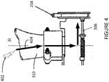
- the current may propagate to the feedback ring 204 via the rods 306, along an electrical conductive path illustrated by arrows 404.
- the feedback ring 204 may carry a charge that can damage the propeller feedback sensing system or cause a risk to its operation.
- lightning may magnetize the feedback ring 204 and generate false triggering of the sensor (reference 212 in Figure 2 ).
- At least one shielding element between the propeller 130 and the feedback ring 204 in order to reduce or remove the electrical conductive path (illustrated by arrows 404 in Figure 4 ) for lightning and/or shield the feedback ring 204 from magnetism (e.g. resulting from a lightning strike or occurring in the field or during machining of the feedback ring 204).
- the at least one shielding element shields the feedback ring 204 from electromagnetism.
- the rod assembly which supports the feedback ring 204 for longitudinal sliding movement, is made non-conductive.
- This may be achieved by making the propellers rods 306 from a non-conductive material (instead of a metallic material), such as a polymer or ceramic type material with electrical insulating properties.
- the inserts (also referred to as bushings or sleeves) 502, which the rods 306 thread into, may be made from a non-conductive material.
- the inserts 502 may be spaced around a circumference of the feedback ring 204.
- a threaded aperture 504 may be formed in each insert 502 for receiving therein a given rod 306.
- a suitable attachment means such as a jam-nut 506, may be provided to secure each insert 502 to the feedback ring 204.
- the non-conductive material may comprise any suitable material, including but not limited to, a ceramic material, a non-conductive polymer, and a composite, that allows to electrically isolate the conductive path (reference 404 in Figure 4 ) between the propeller 130 and the feedback ring 204.
- propeller feedback ring magnetism and arc may in another embodiment be prevented by electrically isolating the position markers 202 from the rods 306, in order to avoid a conductive path for lightning.
- This is achieved by using a non-conductive material as a barrier in the feedback ring 204.
- the non-conductive material serves as an electrical insulator that electrically disconnects the signal inducing position markers 202 from the feedback ring's support base (i.e. the rods 306), and therefore from propeller 130.
- the feedback ring 204 is made of a non-conductive material (e.g. plastic, composite or polymer) that supports the position markers 202 at appropriate locations.
- the non-conductive material may be a composite material.
- a plurality of metallic (e.g. ferrous) thread inserts 602 may be received in the feedback ring 204 at appropriate locations, each metal thread insert 602 adapted to receive therein a given one of the rods 306.
- a metallic inner ring 702 may be provided to strengthen the rod inserts 602 that the rods (reference 306 in Figure 5 ) are received into.
- the inner ring 702 is illustratively positioned at a distance away from the position markers 202 in order to break the electrical conducive path between the propeller 130 and the feedback ring 204 and achieve the desired shielding effect.
- the feedback ring 204 may therefore comprise the inner ring 702, which supports the rod inserts 602, and an outer ring 704, which is made of a non-conductive material and supports the position markers 202 at appropriate locations.
- the inner ring 702 has a smaller outer diameter than the outer ring 704.
- the inner ring 702 is enclosed in the outer ring 704, with the position markers 202 being encapsulated by the outer ring 704.
- the rod inserts 602 may form an integral part of the inner ring 702 and are illustratively made of the same conductive material (e.g. metal) as the inner ring 702.
- a non-conductive insulator 802 is provided as a separating layer between the position markers 202 and the rods (reference 306 in Figure 5 ).
- the insulator 802 may be provided as a layer that is positioned between a metallic inner ring 804, which receives the threaded inserts 602, and a metallic outer ring 806, which supports the position markers 202.
- the insulator 802 is made from any suitable non-conductive material, such as plastic, a polymer, a ceramic material, or the like.
- propeller feedback ring magnetism and arc may be prevented by providing a layer of insulator coating on the feedback ring 204 (or the sensor 212).
- the insulator coating may be selected to increase the dielectric resistance of the air gap between the feedback ring 204 and the sensor 212, thus preventing lightning from passing through the feedback ring 204.
- the insulator coating may be made of any material that has higher isolating properties than air and does not influence magnetic fields.
- the insulator coating may be made of rubber, ceramic, Teflon, kapton, and the like.
- a number of solutions may be used to prevent magnetic fields present on the feedback ring 204 from falsely triggering the sensor 212.
- a targeted magnetic field blocking nano-plating may be used on the entire feedback ring 204, except for the position markers 202.
- the nano-plating may be used on the root surface (reference 304 in Figure 3 ).
- the feedback ring 204 in order to prevent the feedback ring 204 from becoming magnetized, the feedback ring 204 may be made of a material with high resistivity to becoming magnetized, i.e. a high magnetic permeability and low magnetic remanence material such as a high-permeability alloy.
- a thin layer e.g.
- Mu metal is used as the high magnetic permeability and low magnetic remanence material.
- magnetic shielding made with materials, such as Mu metal works by providing a path for the magnetic field lines around the shielded area. It should however be understood that materials other than Mu metal may apply.
- These high magnetic permeability and low magnetic remanence materials include, but are not limited to, electrical steel, and ferrite ceramics.
- magnetism and arc prevention solutions described herein may be used in combination to provide combined benefits. Indeed, a first solution may be used to electrically isolate the feedback ring 204 from the propeller 130 and a second solution may be used to shield the feedback ring 204 from magnetism.
- the rods 306 may be made from a non-conductive material, as discussed above with reference to Figure 5A and Figure 5B , while a layer of Mu metal is applied on the root surface 304 of the feedback ring 204.
Landscapes
- Engineering & Computer Science (AREA)
- Aviation & Aerospace Engineering (AREA)
- Mechanical Engineering (AREA)
- General Engineering & Computer Science (AREA)
- Architecture (AREA)
- Measurement Of Length, Angles, Or The Like Using Electric Or Magnetic Means (AREA)
- Transmission And Conversion Of Sensor Element Output (AREA)
Description
- The present disclosure relates generally to engines, and more specifically to propeller blade angle position feedback systems.
- On featherable propeller systems, it is desirable to accurately measure the propeller blade (or beta) angle to ensure that the blade angle is controlled according to the engine power set-point requested, such as in reverse and low pitch situations, also known as the beta operating region.
- Some propeller feedback systems use a phonic wheel, sometimes referred to as a beta or feedback ring, which can be vulnerable to magnetism and arc, e.g. upon a lightning strike to the propeller. Errant magnetic fields on the feedback ring may also cause false triggering of the sensor, leading to inaccurate measurements.
- Therefore, improvements are needed.
- A prior art blade angle feedback ring assembly, having the features of the preamble of claim 1, is disclosed in
EP 3284666 A1 . - In accordance with a first aspect of the present invention, there is provided a blade angle feedback ring assembly for an aircraft propeller as set forth in claim 1.
- In some embodiments, the plurality of threaded inserts are made from a ceramic material.
- In some embodiments, the feedback ring is made from a non-conductive polymer.
- In some embodiments, the feedback ring comprises a plurality of position markers spaced around a circumference thereof and oriented at an angle relative to one another and relative to the longitudinal axis, the feedback ring further comprising a metallic inner ring configured to receive the plurality of rods therein and an outer ring configured to encapsulate the plurality of position markers, the at least one shielding element comprising the outer ring being made from a non-conductive material.
- In some embodiments, the outer ring is made from a non-conductive polymer.
- In some embodiments, the feedback ring comprises a plurality of position markers spaced around a circumference thereof and oriented at an angle relative to one another and relative to the longitudinal axis, the feedback ring further comprising a metallic inner ring configured to receive the plurality of rods therein and a metallic outer ring configured to support the plurality of position markers thereon, the at least one shielding element comprising a separating layer disposed between the inner ring and the outer ring, the separating layer made from a non-conductive material.
- In some embodiments, the feedback ring assembly further comprises at least one sensor mounted adjacent the feedback ring and configured to detect, as the feedback ring rotates, passage of a plurality of position markers spaced around a circumference of the feedback ring, the at least one shielding element comprising an insulator coating applied on the feedback ring for increasing a dielectric resistance of an air gap between the feedback ring and the at least one sensor.
- In some embodiments, the feedback ring assembly further comprises at least one sensor mounted adjacent the feedback ring and configured to detect, as the feedback ring rotates, passage of a plurality of position markers spaced around a circumference of the feedback ring, the at least one shielding element comprising an insulator coating applied on the at least one sensor for increasing a dielectric resistance of an air gap between the feedback ring and the at least one sensor.
- In some embodiments, the feedback ring has first and second opposing faces and defines a root surface that extends and circumscribes the first and second faces, the feedback ring comprising a plurality of position markers spaced around a circumference thereof and oriented at an angle relative to one another and relative to the longitudinal axis, the plurality of position markers extending away from the root surface, the at least one shielding element comprising a magnetic field blocking nano-plating applied on the root surface.
- In some embodiments, the feedback ring has first and second opposing faces and defines a root surface that extends and circumscribes the first and second faces, the feedback ring comprising a plurality of position markers spaced around a circumference thereof and oriented at an angle relative to one another and relative to the longitudinal axis, the plurality of position markers extending away from the root surface, the at least one shielding element comprising a coating applied on the root surface, the coating made of Mu metal, electrical steel or ferrite ceramics.
- In accordance with a second aspect of the present invention, there is provided a blade angle feedback ring assembly for an aircraft propeller as set forth in claim 10.
- In accordance with a third aspect of the present invention, there is provided a blade angle feedback ring assembly for an aircraft propeller as set forth in claim 11.
- In accordance with a fourth aspect of the present invention, there is provided a blade angle feedback ring assembly for an aircraft propeller as set forth in claim 12.
- In accordance with a fifth aspect of the present invention, there is provided an aircraft propeller system as set forth in claim 13.
- Features of the systems, devices, and methods described herein may be used in various combinations, in accordance with the embodiments described herein.
- Reference is now made to the accompanying figures in which:
-
Figure 1 is a schematic cross-sectional view of an example gas turbine engine; -
Figure 2 is a schematic diagram of an example propeller feedback sensing system; -
Figure 3 is a schematic diagram of the propeller ofFigure 1 with the feedback ring ofFigure 2 , in accordance with an embodiment; -
Figure 4 is a schematic diagram of the electrical conductive path from the propeller ofFigure 1 with the feedback ring ofFigure 2 , in accordance with an embodiment; -
Figure 5A and 5B are schematic diagrams of the feedback ring ofFigure 3 with a non-conductive rod assembly, in accordance with an embodiment; -
Figure 6A and Figure 6B are schematic diagrams of the feedback ring ofFigure 3 with the feedback ring being made of a non-conductive material to electrically isolate the position markers from the feedback rods, in accordance with an embodiment; -
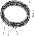
Figure 7A andFigure 7B are schematic diagrams of the feedback ring ofFigure 3 with the feedback ring being made of a non-conductive material to electrically isolate the position markers from the feedback rods, in accordance with another embodiment; and -
Figure 8 is a schematic diagram of the feedback ring ofFigure 3 with an insulating layer being positioned between the position markers and the feedback rods, in accordance with another embodiment. - It will be noted that throughout the appended drawings, like features are identified by like reference numerals.
-
Figure 1 depicts agas turbine engine 110 of a type typically provided for use in subsonic flight. Theengine 110 comprises aninlet 112 through which ambient air is propelled, acompressor section 114 for pressurizing the air, acombustor 116 in which the compressed air is mixed with fuel and ignited for generating an annular stream of hot combustion gases, and aturbine section 118 for extracting energy from the combustion gases. - The
turbine section 118 comprises acompressor turbine 120, which drives the compressor assembly and accessories, and at least one power orfree turbine 122, which is independent from thecompressor turbine 120 and rotatingly drives arotor shaft 124 about a propeller shaft axis 'A' through areduction gearbox 126. Hot gases may then be evacuated throughexhaust stubs 128. The gas generator of theengine 110 comprises thecompressor section 114, thecombustor 116, and theturbine section 118. - A rotor, in the form of a
propeller 130 through which ambient air is propelled, is hosted in apropeller hub 132. The rotor may, for example, comprise thepropeller 130 of a fixed-wing aircraft, or a main (or tail) rotor of a rotary-wing aircraft such as a helicopter. Thepropeller 130 may comprise a plurality of circumferentially-arranged blades connected to a hub by any suitable means and extending radially therefrom. The blades are also each rotatable about their own radial axes through a plurality of blade angles, which can be changed to achieve modes of operation, such as feather, full reverse, and forward thrust. - With reference to
Figure 2 , asystem 200 for sensing a feedback ring (also referred to as a phonic wheel) 204 of an aircraft propeller will now be described. In some embodiments, thesystem 200 provides for detection and measurement of rotational velocity of one or more rotating elements of theengine 110 and of propeller blade angle on propeller systems, such as thepropeller 130 ofFigure 1 . Thesystem 200 may interface to existing mechanical interfaces of typical propeller systems to provide a digital detection for electronic determination of the propeller blade angle. It should be noted that although the present disclosure focuses on the use of thesystem 200 and thefeedback ring 204 in gas-turbine engines, similar techniques can be applied to other types of engines, including electric engines. - The
system 200 comprises anannular member 204 and one ormore sensors 212 positioned proximate theannular member 204. Annular member 204 (referred to herein as a feedback ring) has a plurality of position markers (also referred to as teeth) 202 provided thereon for detection bysensor 212. In some embodiments, thefeedback ring 204 is mounted for rotation withpropeller 130 and to move axially with adjustment of the blade angle of the blades of thepropeller 130, and thesensor 212 is fixedly mounted to a static portion of theengine 110. In other embodiments, thesensor 212 is mounted for rotation withpropeller 130 and to move axially with adjustment of the blade angle of the blades of thepropeller 130, and thefeedback ring 204 is fixedly mounted to a static portion of theengine 110. - The
system 200 also includes acontroller 220 communicatively coupled to thesensor 212. Thesensor 212 is configured for producing a sensor signal which is transmitted to or otherwise received by thecontroller 220, for example via adetection unit 222 thereof. The sensor signal can be an electrical signal, digital or analog, an optical signal, or any other suitable type of signal. In some embodiments, thesensor 212 produces a series of signal pulses in response to detecting the presence of aposition marker 202 in a sensing zone of thesensor 212. For example, thesensor 212 operates on detecting changes in magnetic flux, and has a sensing zone which encompasses a circular or rectangular area or volume in front of thesensor 212. When aposition marker 202 is present in the zone, or passes through the zone during rotation of thefeedback ring 204, the magnetic flux in the sensing zone is varied by the presence of theposition marker 202, and thesensor 212 can produce a signal pulse, which forms part of the sensor signal. - It should be understood that, although the preceding paragraphs focus on the use of the
sensor 212 which detects changes in magnetic flux due to the presence of one of theposition markers 202 in the sensing zone of the sensor, other types of sensors are also considered. - In the example illustrated in
Figure 2 , a side view of a portion offeedback ring 204 andsensor 212 is shown. Thesensor 212 is mounted to aflange 214 of a housing of thereduction gearbox 126, so as to be positioned adjacent the plurality ofposition markers 202. In some embodiments, thesensor 212 is secured to thepropeller 130 so as to extend away from theflange 214 and towards theposition markers 202 along a radial direction, identified inFigure 2 as direction 'R'.Sensor 212 andflange 214 may be fixedly mounted, for example to the housing of thereduction gearbox 126, or to any other static element of theengine 110, as appropriate. - In some embodiments, a
single sensor 212 is mounted in close proximity to thefeedback ring 204 and theposition markers 202. In some other embodiments, in order to provide redundancy, one or more additional sensors, which may be similar to thesensor 212, are provided. For example, anadditional sensor 212 may be mounted in a diametrically opposite relationship, or at any angle, relative to theposition markers 202, which extend away from thefeedback ring 204 and towards the sensor(s) 212. In yet another embodiment,several position markers 202 may be spaced equiangularly about the perimeter of the feedback ring 104. Other embodiments may apply. - With additional reference to
Figure 3 , in some embodiments thefeedback ring 204 is embodied as a circular disk which rotates as part of theengine 110, for example with theoutput shaft 124 or with thepropeller 130. Thefeedback ring 204 comprises opposing faces 302 and defines aroot surface 304 which extends between the opposing faces 302 and circumscribes them. Put differently, theroot surface 304 of thefeedback ring 204 is the outer periphery of the circular disk which spans between the two opposing faces 302. In these embodiments, theposition markers 202 can take the form of projections which extend from theroot surface 304. - The
position markers 202 may comprise a plurality of first projections (not shown) arranged along a direction substantially transverse to the opposing faces and substantially equally spaced from one another on theroot surface 304. Theposition markers 202 may also comprise one or more second projections (not shown) each positioned between two adjacent first projections. Each second projection is illustratively oriented along a direction, which is at an angle relative to direction along which the first projections are arranged. The angle can be any suitable value between 1° and 89°, for example 30°, 45°, 60°, or any other value, as appropriate. It should be noted, however, that in some other embodiments the second projection(s) can be cooriented with the first projections. It should also be noted that in some embodiments, each second projection can be substituted for a groove or inward projection, as appropriate. In addition, in some embodiments, thefeedback ring 204 includes only a single second projection while, in other embodiments, thefeedback ring 204 can include more than one second projections. In the latter case, the second projections can be oriented along a common orientation or along one or more different orientations and each second projection can be located at substantially a midpoint between two adjacent first projections or can be located close to a particular one of two adjacent first projections. - It should be noted, however, that other embodiments are also considered. In some embodiments, the position markers can be applied to the
root surface 304, for instance as strips of metal or other material for detection by thesensor 212, which can be a magnetic flux sensor. In some other embodiments, the position markers can be coloured or contrasting bands of material applied to theroot surface 304 for detection by thesensor 212, which can be an optical sensor. Still other embodiments are considered. - The signal pulses produced by the
sensor 212, which form part of the electrical signal received by thecontrol system 220, can be used to determine various operating parameters of theengine 110 and thepropeller 130. The regular spacing of the first projections can, for example, be used to determine a speed of rotation of thefeedback ring 204. In addition, the second projection(s) can be detected by thesensor 212 to determine a blade angle of thepropeller 130. - With continued reference to
Figure 3 , thefeedback ring 204 is supported for rotation with thepropeller 130, which rotates about the longitudinal axis 'A'. Thefeedback ring 204 is also supported for longitudinal sliding movement along the axis A, e.g. by support members, such as a series of circumferentially spacedfeedback rods 306 that extend along the longitudinal axis 'A'. A compression spring 308 surrounds an end portion of eachrod 306. - As depicted in
Figure 3 , thepropeller 130 comprises a plurality of angularly arrangedblades 310, each of which is rotatable about a radially-extending axis 'R' through a plurality of adjustable blade angles, the blade angle being the angle between the chord line (i.e. a line drawn between the leading and trailing edges of the blade) of the propeller blade section and a plane perpendicular to the axis of propeller rotation. In some embodiments, thepropeller 130 is a reversing propeller, capable of operating in a variety of modes of operation, including feather, full reverse, and forward thrust. Depending on the mode of operation, the blade angle may be positive or negative: the feather and forward thrust modes are associated with positive blade angles, and the full reverse mode is associated with negative blade angles. - Referring now to
Figure 4 in addition toFigure 3 , upon alightning strike 402 to thepropeller 130, a current is generated that may propagate from the propeller 130 (e.g. from the blades 310) to thefeedback ring 204. In particular, in existing system where therods 306 are metallic (e.g. made of a stainless steel alloy or any other suitable material), the current may propagate to thefeedback ring 204 via therods 306, along an electrical conductive path illustrated byarrows 404. As a result, thefeedback ring 204 may carry a charge that can damage the propeller feedback sensing system or cause a risk to its operation. In addition, lightning may magnetize thefeedback ring 204 and generate false triggering of the sensor (reference 212 inFigure 2 ). Moreover, because the position markers (reference 202 inFigure 2 ) potentially have a low clearance with thesensor 212, lightning current can arc across the air gap between thefeedback ring 204 and thesensor 212. This may in turn result in unwanted magnetization of thefeedback ring 204 and unacceptably high current levels on the engine harness attached to thesensor 212. - In order to prevent unwanted propeller feedback ring magnetism and arc, it is proposed herein to provide at least one shielding element between the
propeller 130 and thefeedback ring 204 in order to reduce or remove the electrical conductive path (illustrated byarrows 404 inFigure 4 ) for lightning and/or shield thefeedback ring 204 from magnetism (e.g. resulting from a lightning strike or occurring in the field or during machining of the feedback ring 204). In other words, the at least one shielding element shields thefeedback ring 204 from electromagnetism. - Referring to
Figure 5A and Figure 5B , in one embodiment, the rod assembly, which supports thefeedback ring 204 for longitudinal sliding movement, is made non-conductive. This may be achieved by making thepropellers rods 306 from a non-conductive material (instead of a metallic material), such as a polymer or ceramic type material with electrical insulating properties. Alternatively, the inserts (also referred to as bushings or sleeves) 502, which therods 306 thread into, may be made from a non-conductive material. Theinserts 502 may be spaced around a circumference of thefeedback ring 204. A threaded aperture 504 may be formed in eachinsert 502 for receiving therein a givenrod 306. A suitable attachment means, such as a jam-nut 506, may be provided to secure eachinsert 502 to thefeedback ring 204. The non-conductive material may comprise any suitable material, including but not limited to, a ceramic material, a non-conductive polymer, and a composite, that allows to electrically isolate the conductive path (reference 404 inFigure 4 ) between thepropeller 130 and thefeedback ring 204. - Referring now to
Figure 6A, Figure 6B ,Figure 7A ,Figure 7B , andFigure 8 , propeller feedback ring magnetism and arc may in another embodiment be prevented by electrically isolating theposition markers 202 from therods 306, in order to avoid a conductive path for lightning. This is achieved by using a non-conductive material as a barrier in thefeedback ring 204. In particular, the non-conductive material serves as an electrical insulator that electrically disconnects the signal inducingposition markers 202 from the feedback ring's support base (i.e. the rods 306), and therefore frompropeller 130. - In the embodiment illustrated in
Figure 6A and Figure 6B , thefeedback ring 204 is made of a non-conductive material (e.g. plastic, composite or polymer) that supports theposition markers 202 at appropriate locations. The non-conductive material may be a composite material. A plurality of metallic (e.g. ferrous) thread inserts 602 may be received in thefeedback ring 204 at appropriate locations, eachmetal thread insert 602 adapted to receive therein a given one of therods 306. - As shown in
Figure 7A andFigure 7B , in another embodiment, a metallicinner ring 702 may be provided to strengthen the rod inserts 602 that the rods (reference 306 inFigure 5 ) are received into. Theinner ring 702 is illustratively positioned at a distance away from theposition markers 202 in order to break the electrical conducive path between thepropeller 130 and thefeedback ring 204 and achieve the desired shielding effect. Thefeedback ring 204 may therefore comprise theinner ring 702, which supports the rod inserts 602, and anouter ring 704, which is made of a non-conductive material and supports theposition markers 202 at appropriate locations. Theinner ring 702 has a smaller outer diameter than theouter ring 704. In one embodiment, theinner ring 702 is enclosed in theouter ring 704, with theposition markers 202 being encapsulated by theouter ring 704. The rod inserts 602 may form an integral part of theinner ring 702 and are illustratively made of the same conductive material (e.g. metal) as theinner ring 702. - Referring now to
Figure 8 , in another embodiment, instead of making thefeedback ring 204 from a non-conductive material, anon-conductive insulator 802 is provided as a separating layer between theposition markers 202 and the rods (reference 306 inFigure 5 ). In particular, theinsulator 802 may be provided as a layer that is positioned between a metallicinner ring 804, which receives the threadedinserts 602, and a metallicouter ring 806, which supports theposition markers 202. Theinsulator 802 is made from any suitable non-conductive material, such as plastic, a polymer, a ceramic material, or the like. - Referring back to
Figure 2 , in yet another embodiment, propeller feedback ring magnetism and arc may be prevented by providing a layer of insulator coating on the feedback ring 204 (or the sensor 212). The insulator coating may be selected to increase the dielectric resistance of the air gap between thefeedback ring 204 and thesensor 212, thus preventing lightning from passing through thefeedback ring 204. The insulator coating may be made of any material that has higher isolating properties than air and does not influence magnetic fields. For example, the insulator coating may be made of rubber, ceramic, Teflon, kapton, and the like. Alternatively, a number of solutions may be used to prevent magnetic fields present on thefeedback ring 204 from falsely triggering thesensor 212. For example, a targeted magnetic field blocking nano-plating may be used on theentire feedback ring 204, except for theposition markers 202. In other words, the nano-plating may be used on the root surface (reference 304 inFigure 3 ). In another embodiment, in order to prevent thefeedback ring 204 from becoming magnetized, thefeedback ring 204 may be made of a material with high resistivity to becoming magnetized, i.e. a high magnetic permeability and low magnetic remanence material such as a high-permeability alloy. In yet another embodiment, a thin layer (e.g. of thickness in the range of 0.5 to 2.0 mm (0.020 inches to 0.080 inches)) of the high magnetic permeability and low magnetic remanence material may be applied on theroot surface 304, between eachposition marker 202, in order to prevent magnetized spots on thefeedback ring 204 from falsely triggering thesensor 212. In one embodiment, Mu metal is used as the high magnetic permeability and low magnetic remanence material. As known to those skilled in the art, magnetic shielding made with materials, such as Mu metal, works by providing a path for the magnetic field lines around the shielded area. It should however be understood that materials other than Mu metal may apply. These high magnetic permeability and low magnetic remanence materials include, but are not limited to, electrical steel, and ferrite ceramics. - It should be understood that the magnetism and arc prevention solutions described herein may be used in combination to provide combined benefits. Indeed, a first solution may be used to electrically isolate the
feedback ring 204 from thepropeller 130 and a second solution may be used to shield thefeedback ring 204 from magnetism. For example, therods 306 may be made from a non-conductive material, as discussed above with reference toFigure 5A and Figure 5B , while a layer of Mu metal is applied on theroot surface 304 of thefeedback ring 204. - The above description is meant to be exemplary only, and one skilled in the art will recognize that changes may be made to the embodiments described without departing from the scope of the claims.
Claims (13)
- A blade angle feedback ring assembly (200) for an aircraft propeller (130) rotatable about a longitudinal axis (A) and having an adjustable blade angle, the assembly (200) comprising:a feedback ring (204) for coupling to the propeller (130) to rotate with the propeller (130) and to move along the longitudinal axis (A) with adjustment of the blade angle; anda plurality of rods (306) coupled to the feedback ring (204) and extending along a direction substantially parallel to the longitudinal axis (A), the plurality of rods (306) configured to support the feedback ring (204) for longitudinal sliding movement along the longitudinal axis (A) with adjustment of the blade angle,characterised in that:
the assembly (200) comprises at least one shielding element configured to shield the feedback ring (204) from electromagnetism, wherein the at least one shielding element comprises at least one of:the plurality of rods (306) being made from a non-conductive material;the feedback ring (204) being made from a non-conductive material, Mu metal, electrical Z f steel or ferrite ceramics; anda plurality of threaded inserts (502) being made from a non-conductive material, wherein the feedback ring (204) comprises the plurality of threaded inserts (502) spaced around a circumference of the feedback ring (204) and each configured to receive therein a given one of the plurality of rods (306). - The feedback ring assembly (200) of claim 1, wherein, when the at least one shielding element comprises the plurality of threaded inserts (502) being made from a non-conductive material, the plurality of threaded inserts (502) are made from a ceramic material.
- The feedback ring assembly (200) of claim 1 or 2, wherein, when the at least one shielding element comprises the feedback ring (204) being made from a non-conductive material, the feedback ring (204) is made from a non-conductive polymer.
- The feedback ring assembly (200) of claim 1, 2 or 3, wherein the feedback ring (204) comprises a plurality of position markers (202) spaced around a circumference thereof and oriented at an angle relative to one another and relative to the longitudinal axis (A), the feedback ring (204) further comprising a metallic inner ring (702) configured to receive the plurality of rods (306) therein and an outer ring (704) configured to encapsulate the plurality of position markers (202), the at least one shielding element comprising the outer ring (704) being made from a non-conductive material, wherein, optionally, the outer ring (704) is made from a non-conductive polymer.
- The feedback ring assembly (200) of claim 1, 2 or 3, wherein the feedback ring (204) comprises a plurality of position markers (202) spaced around a circumference thereof and oriented at an angle relative to one another and relative to the longitudinal axis (A), the feedback ring (204) further comprising a metallic inner ring (804) configured to receive the plurality of rods (306) therein and a metallic outer ring (806) configured to support the plurality of position markers (202) thereon, the at least one shielding element comprising a separating layer disposed between the inner ring (804) and the outer ring (806), the separating layer made from a non-conductive material.
- The feedback ring assembly (200) of any preceding claim, further comprising at least one sensor (212) mounted adjacent the feedback ring (204) and configured to detect, as the feedback ring (204) rotates, passage of a plurality of position markers (202), or the plurality of position markers (202) when dependent on claim 4, spaced around a circumference of the feedback ring (204), the at least one shielding element comprising an insulator coating applied on the feedback ring (204) for increasing a dielectric resistance of an air gap between the feedback ring (204) and the at least one sensor (212).
- The feedback ring assembly (200) of any of claims 1 to 5, further comprising at least one sensor (212) mounted adjacent the feedback ring (204) and configured to detect, as the feedback ring (204) rotates, passage of a plurality of position markers (202), or the plurality of position markers (202) when dependent on claim 4, spaced around a circumference of the feedback ring (204), the at least one shielding element comprising an insulator coating applied on the at least one sensor (212) for increasing a dielectric resistance of an air gap between the feedback ring (204) and the at least one sensor (212).
- The feedback ring assembly (200) of any preceding claim, wherein the feedback ring (204) has first and second opposing faces (302) and defines a root surface (304) that extends and circumscribes the first and second opposing faces (302), the feedback ring (204) comprising a plurality of position markers (202), or the plurality of position markers (202) when dependent on claim 4, spaced around a circumference thereof and oriented at an angle relative to one another and relative to the longitudinal axis (A), the plurality of position markers (202) extending away from the root surface (304), the at least one shielding element comprising a magnetic field blocking nano-plating applied on the root surface (304).
- The feedback ring assembly (200) of any of claims 1 to 7, wherein the feedback ring (204) has first and second opposing faces (302) and defines a root surface (304) that extends and circumscribes the first and second opposing faces (302), the feedback ring (204) comprising a plurality of position markers (202), or the plurality of position markers (202) when dependent on claim 4, spaced around a circumference thereof and oriented at an angle relative to one another and relative to the longitudinal axis (A), the plurality of position markers (202) extending away from the root surface (304), the at least one shielding element comprising a coating applied on the root surface (304), the coating made of Mu metal, electrical steel, or ferrite ceramics
- A blade angle feedback ring assembly (200) for an aircraft propeller (130) rotatable about a longitudinal axis (A) and having an adjustable blade angle, the assembly (200) comprising:a feedback ring (204) for coupling to the propeller (130) to rotate with the propeller (130) and to move along the longitudinal axis (A) with adjustment of the blade angle, wherein the feedback ring (204) comprises a plurality of position markers (202) spaced around a circumference thereof and oriented at an angle relative to one another and relative to the longitudinal axis (A); anda plurality of rods (306) coupled to the feedback ring (204) and extending along a direction substantially parallel to the longitudinal axis (A), the plurality of rods (306) configured to support the feedback ring (204) for longitudinal sliding movement along the longitudinal axis (A) with adjustment of the blade angle,characterised in that:the feedback ring (204) further comprises a metallic inner ring (702) configured to receive the plurality of rods (306) therein; andthe assembly (200) comprises at least one shielding element configured to be provided between the feedback ring and the propeller, the at least one shielding element configured to shield the feedback ring (204) from electromagnetism, wherein the feedback ring further comprises:either an outer ring (704) configured to encapsulate the plurality of position markers (202) and the at least one shielding element comprises the outer ring (704) being made from a non-conductive material; ora metallic outer ring (806) configured to support the plurality of position markers (202) thereon and the at least one shielding element comprises a separating layer disposed between the inner ring (804) and the outer ring (806), the separating layer being made from a non-conductive material.
- A blade angle feedback ring assembly (200) for an aircraft propeller (130) rotatable about a longitudinal axis (A) and having an adjustable blade angle, the assembly (200) comprising:a feedback ring (204) for coupling to the propeller (130) to rotate with the propeller (130) and to move along the longitudinal axis (A) with adjustment of the blade angle;a plurality of rods (306) coupled to the feedback ring (204) and extending along a direction substantially parallel to the longitudinal axis (A), the plurality of rods (306) configured to support the feedback ring (204) for longitudinal sliding movement along the longitudinal axis (A) with adjustment of the blade angle; andat least one sensor (212) mounted adjacent the feedback ring (204) and configured to detect, as the feedback ring (204) rotates, passage of a plurality of position markers (202) spaced around a circumference of the feedback ring (204),characterised in that:
the assembly (200) comprises at least one shielding element configured to shield the feedback ring (204) from electromagnetism, the at least one shielding element comprising an insulator coating applied on the feedback ring (204) or the at least one sensor (212) for increasing a dielectric resistance of an air gap between the feedback ring (204) and the at least one sensor (212). - A blade angle feedback ring assembly (200) for an aircraft propeller (130) rotatable about a longitudinal axis (A) and having an adjustable blade angle, the assembly (200) comprising:a feedback ring (204) for coupling to the propeller (130) to rotate with the propeller (130) and to move along the longitudinal axis (A) with adjustment of the blade angle, wherein the feedback ring (204) has first and second opposing faces (302) and defines a root surface (304) that extends and circumscribes the first and second opposing faces (302), the feedback ring (204) comprising a plurality of position markers (202) spaced around a circumference thereof and oriented at an angle relative to one another and relative to the longitudinal axis (A), the plurality of position markers (202) extending away from the root surface (304); anda plurality of rods (306) coupled to the feedback ring (204) and extending along a direction substantially parallel to the longitudinal axis (A), the plurality of rods (306) configured to support the feedback ring (204) for longitudinal sliding movement along the longitudinal axis (A) with adjustment of the blade angle,characterised in that:
the assembly (200) comprises at least one shielding element configured to shield the feedback ring (204) from electromagnetism, the at least one shielding element comprising a magnetic field blocking nano-plating applied on the root surface (304), or a coating made of Mu metal, electrical steel or ferrite ceramics applied on the root surface (304). - An aircraft propeller system comprising:a propeller (130) rotatable about a longitudinal axis (A) and having blades (310) with adjustable blade angle; andthe feedback ring assembly (200) according to any preceding claim.
Priority Applications (1)
| Application Number | Priority Date | Filing Date | Title |
|---|---|---|---|
| EP22164856.1A EP4039584B1 (en) | 2018-07-16 | 2019-07-16 | Propeller blade angle feedback arrangement and method |
Applications Claiming Priority (1)
| Application Number | Priority Date | Filing Date | Title |
|---|---|---|---|
| US16/036,930 US11046422B2 (en) | 2018-07-16 | 2018-07-16 | Propeller blade angle feedback arrangement and method |
Related Child Applications (1)
| Application Number | Title | Priority Date | Filing Date |
|---|---|---|---|
| EP22164856.1A Division EP4039584B1 (en) | 2018-07-16 | 2019-07-16 | Propeller blade angle feedback arrangement and method |
Publications (2)
| Publication Number | Publication Date |
|---|---|
| EP3597532A1 EP3597532A1 (en) | 2020-01-22 |
| EP3597532B1 true EP3597532B1 (en) | 2022-04-13 |
Family
ID=67314685
Family Applications (2)
| Application Number | Title | Priority Date | Filing Date |
|---|---|---|---|
| EP22164856.1A Active EP4039584B1 (en) | 2018-07-16 | 2019-07-16 | Propeller blade angle feedback arrangement and method |
| EP19186592.2A Active EP3597532B1 (en) | 2018-07-16 | 2019-07-16 | Propeller blade angle feedback arrangement and method |
Family Applications Before (1)
| Application Number | Title | Priority Date | Filing Date |
|---|---|---|---|
| EP22164856.1A Active EP4039584B1 (en) | 2018-07-16 | 2019-07-16 | Propeller blade angle feedback arrangement and method |
Country Status (5)
| Country | Link |
|---|---|
| US (2) | US11046422B2 (en) |
| EP (2) | EP4039584B1 (en) |
| CN (1) | CN110725719B (en) |
| CA (1) | CA3049575A1 (en) |
| PL (2) | PL3597532T3 (en) |
Families Citing this family (8)
| Publication number | Priority date | Publication date | Assignee | Title |
|---|---|---|---|---|
| US10486827B2 (en) * | 2016-08-17 | 2019-11-26 | Pratt & Whitney Canada Corp. | Apparatus and methods for aircraft propeller control |
| US10864979B2 (en) * | 2018-06-27 | 2020-12-15 | Pratt & Whitney Canada Corp. | System and method for propeller feedback ring position detection |
| US10829201B2 (en) * | 2019-03-20 | 2020-11-10 | Pratt & Whitney Canada Corp. | Blade angle position feedback system with extended markers |
| US11046423B2 (en) * | 2019-07-18 | 2021-06-29 | Pratt & Whitney Canada Corp. | Blade angle position feedback system with magnetic shield |
| US11365691B2 (en) | 2019-09-05 | 2022-06-21 | Pratt & Whitney Canada Corp. | Blade angle position feedback system with embedded markers |
| US11480585B2 (en) * | 2020-04-17 | 2022-10-25 | Pratt & Whitney Canada Corp. | Hybrid feedback device |
| US20220185451A1 (en) | 2020-12-11 | 2022-06-16 | Pratt & Whitney Canada Corp. | Test rig and method for blade pitch measurement system |
| US11767769B2 (en) | 2020-12-11 | 2023-09-26 | Pratt & Whitney Canada Corp. | Method and system for testing a sensor of a propeller blade angle position feedback system |
Citations (1)
| Publication number | Priority date | Publication date | Assignee | Title |
|---|---|---|---|---|
| EP2883788A1 (en) * | 2013-12-02 | 2015-06-17 | MT-Propeller Entwicklung GmbH | Propeller unit with controller |
Family Cites Families (26)
| Publication number | Priority date | Publication date | Assignee | Title |
|---|---|---|---|---|
| US5102302A (en) * | 1988-06-02 | 1992-04-07 | General Electric Company | Fan blade mount |
| GB2221306A (en) | 1988-07-29 | 1990-01-31 | Dowty Rotol Ltd | Assembly for determining the longitudinal displacement of a rotating shaft |
| US4934901A (en) | 1989-04-21 | 1990-06-19 | Duchesneau Jerome G | Pitch change actuation system |
| US5913659A (en) | 1993-11-22 | 1999-06-22 | United Technologies Corporation | Apparatus and method for adjusting rotor blade tracking |
| FR2741591B1 (en) * | 1995-11-29 | 1998-01-30 | Eurocopter France | BLADE WITH REINFORCED PROTECTION AGAINST LIGHTNING, FOR ROTOR OF A GIRAVION |
| US5897293A (en) | 1996-11-22 | 1999-04-27 | United Technologies Corporation | Counterweighted propeller control system |
| US6077040A (en) | 1998-05-01 | 2000-06-20 | United Technologies Corporation | Control system for blades for a variable pitch propeller |
| US6672835B1 (en) * | 2003-05-19 | 2004-01-06 | Arthur C. Hughes | Method and apparatus for self-contained variable pitch and/or constant speed propeller including provisions for feathering and reverse pitch operation |
| NO20054704D0 (en) | 2005-10-13 | 2005-10-13 | Sway As | Method and method for wind turbines and propulsion systems with magnetically stable main bearing and load control system |
| JP5610758B2 (en) * | 2009-04-02 | 2014-10-22 | 三菱航空機株式会社 | Lightning-resistant fastener, cap, lightning-fastener installation method, aircraft |
| JP5846587B2 (en) * | 2009-04-02 | 2016-01-20 | 三菱航空機株式会社 | Attaching lightning-resistant fasteners, aircraft, lightning-resistant fasteners |
| GB201004469D0 (en) * | 2010-03-18 | 2010-05-05 | Rolls Royce Plc | Controlling blade pitch angle |
| FR2960217A1 (en) * | 2010-05-24 | 2011-11-25 | Eurocopter France | ROTOR WITH A DEVICE FOR PROTECTION AGAINST LIGHTNING, AND AIRCRAFT PROVIDED WITH SAID ROTOR |
| EP2629407B1 (en) * | 2012-02-17 | 2014-12-24 | Bell Helicopter Textron Inc. | Electrical generator for rotating structure |
| US8687206B2 (en) | 2012-05-29 | 2014-04-01 | United Technologies Corporation | Optical detection of airfoil axial position with NSMS |
| US20140007591A1 (en) | 2012-07-03 | 2014-01-09 | Alexander I. Khibnik | Advanced tip-timing measurement blade mode identification |
| WO2014049257A1 (en) * | 2012-09-28 | 2014-04-03 | Snecma | Hydraulic and electrical interface ring for a turbine engine |
| FR3011818B1 (en) * | 2013-10-11 | 2015-12-25 | Eurocopter France | ADAPTIVE ROTATING BLADE, AND AIRCRAFT PROVIDED WITH SUCH A BLADE |
| US9821901B2 (en) | 2013-11-21 | 2017-11-21 | Pratt & Whitney Canada Corp. | System and method for electronic propeller blade angle position feedback |
| US9702255B2 (en) * | 2013-11-26 | 2017-07-11 | Textron Innovations, Inc. | Propeller with lightening strike protection |
| US10450863B2 (en) * | 2016-06-02 | 2019-10-22 | General Electric Company | Turbine engine shaft torque sensing |
| US10486827B2 (en) * | 2016-08-17 | 2019-11-26 | Pratt & Whitney Canada Corp. | Apparatus and methods for aircraft propeller control |
| US10435140B2 (en) * | 2016-08-17 | 2019-10-08 | Pratt & Whitney Canada Corp. | System and method for electronic propeller blade angle position feedback with angled pairs of teeth |
| US10889367B2 (en) * | 2017-04-24 | 2021-01-12 | Pratt & Whitney Canada Corp. | Feedback system for pitch-adjustable blades of aircraft bladed rotor |
| US10611462B2 (en) * | 2017-08-18 | 2020-04-07 | The Boeing Company | Actuator assemblies for control surfaces of an aircraft, aircraft including the actuator assemblies, and methods of utilizing the same |
| EP3533710B1 (en) * | 2018-02-28 | 2021-01-27 | AIRBUS HELICOPTERS DEUTSCHLAND GmbH | A passive pitch angle adjustment apparatus |
-
2018
- 2018-07-16 US US16/036,930 patent/US11046422B2/en active Active
-
2019
- 2019-07-12 CA CA3049575A patent/CA3049575A1/en active Pending
- 2019-07-16 EP EP22164856.1A patent/EP4039584B1/en active Active
- 2019-07-16 PL PL19186592.2T patent/PL3597532T3/en unknown
- 2019-07-16 PL PL22164856.1T patent/PL4039584T3/en unknown
- 2019-07-16 EP EP19186592.2A patent/EP3597532B1/en active Active
- 2019-07-16 CN CN201910640448.2A patent/CN110725719B/en active Active
-
2021
- 2021-05-21 US US17/326,993 patent/US11780561B2/en active Active
Patent Citations (1)
| Publication number | Priority date | Publication date | Assignee | Title |
|---|---|---|---|---|
| EP2883788A1 (en) * | 2013-12-02 | 2015-06-17 | MT-Propeller Entwicklung GmbH | Propeller unit with controller |
Non-Patent Citations (1)
| Title |
|---|
| CS-P EASA: "European Aviation Safety Agency Certification Specifications for Propellers", 23 October 2003 (2003-10-23), pages 1 - 28, XP055733695, Retrieved from the Internet <URL:https://www.easa.europa.eu/sites/default/files/dfu/CS-P%20Initial%20Issue%202003.pdf> [retrieved on 20200924] * |
Also Published As
| Publication number | Publication date |
|---|---|
| US20210284322A1 (en) | 2021-09-16 |
| EP4039584A1 (en) | 2022-08-10 |
| CA3049575A1 (en) | 2020-01-16 |
| EP3597532A1 (en) | 2020-01-22 |
| US11046422B2 (en) | 2021-06-29 |
| US20200017234A1 (en) | 2020-01-16 |
| US11780561B2 (en) | 2023-10-10 |
| EP4039584B1 (en) | 2025-10-08 |
| CN110725719A (en) | 2020-01-24 |
| PL3597532T3 (en) | 2022-07-18 |
| CN110725719B (en) | 2024-06-14 |
| PL4039584T3 (en) | 2026-01-26 |
Similar Documents
| Publication | Publication Date | Title |
|---|---|---|
| EP4039584B1 (en) | Propeller blade angle feedback arrangement and method | |
| EP3597533B1 (en) | Propeller blade angle feedback arrangement and method | |
| US9821901B2 (en) | System and method for electronic propeller blade angle position feedback | |
| EP3284665B1 (en) | System and method for electronic propeller blade angle position feedback with angled pairs of teeth | |
| CA3077940A1 (en) | Blade angle position feedback system with offset sensors | |
| EP3712057B1 (en) | Blade angle position feedback system with extended markers | |
| EP3744630B1 (en) | Feedback device with differing magnetic permeability zones | |
| US20210071589A1 (en) | Pitch control assembly for an aircraft-bladed rotor | |
| US11623735B2 (en) | Blade angle position feedback system with magnetic shield | |
| EP3744629B1 (en) | Feedback device with non-axially aligned position markers | |
| US11643187B2 (en) | Blade angle position feedback system with profiled marker terminations | |
| CA3080300A1 (en) | Feedback device with differing magnetic permeability zones | |
| CA3080296A1 (en) | Feedback device with non-axially aligned position markers |
Legal Events
| Date | Code | Title | Description |
|---|---|---|---|
| PUAI | Public reference made under article 153(3) epc to a published international application that has entered the european phase |
Free format text: ORIGINAL CODE: 0009012 |
|
| STAA | Information on the status of an ep patent application or granted ep patent |
Free format text: STATUS: THE APPLICATION HAS BEEN PUBLISHED |
|
| AK | Designated contracting states |
Kind code of ref document: A1 Designated state(s): AL AT BE BG CH CY CZ DE DK EE ES FI FR GB GR HR HU IE IS IT LI LT LU LV MC MK MT NL NO PL PT RO RS SE SI SK SM TR |
|
| AX | Request for extension of the european patent |
Extension state: BA ME |
|
| TPAC | Observations filed by third parties |
Free format text: ORIGINAL CODE: EPIDOSNTIPA |
|
| STAA | Information on the status of an ep patent application or granted ep patent |
Free format text: STATUS: REQUEST FOR EXAMINATION WAS MADE |
|
| 17P | Request for examination filed |
Effective date: 20200722 |
|
| RBV | Designated contracting states (corrected) |
Designated state(s): AL AT BE BG CH CY CZ DE DK EE ES FI FR GB GR HR HU IE IS IT LI LT LU LV MC MK MT NL NO PL PT RO RS SE SI SK SM TR |
|
| STAA | Information on the status of an ep patent application or granted ep patent |
Free format text: STATUS: EXAMINATION IS IN PROGRESS |
|
| 17Q | First examination report despatched |
Effective date: 20201012 |
|
| GRAP | Despatch of communication of intention to grant a patent |
Free format text: ORIGINAL CODE: EPIDOSNIGR1 |
|
| STAA | Information on the status of an ep patent application or granted ep patent |
Free format text: STATUS: GRANT OF PATENT IS INTENDED |
|
| GRAJ | Information related to disapproval of communication of intention to grant by the applicant or resumption of examination proceedings by the epo deleted |
Free format text: ORIGINAL CODE: EPIDOSDIGR1 |
|
| GRAP | Despatch of communication of intention to grant a patent |
Free format text: ORIGINAL CODE: EPIDOSNIGR1 |
|
| INTG | Intention to grant announced |
Effective date: 20211014 |
|
| INTG | Intention to grant announced |
Effective date: 20211027 |
|
| GRAS | Grant fee paid |
Free format text: ORIGINAL CODE: EPIDOSNIGR3 |
|
| GRAA | (expected) grant |
Free format text: ORIGINAL CODE: 0009210 |
|
| STAA | Information on the status of an ep patent application or granted ep patent |
Free format text: STATUS: THE PATENT HAS BEEN GRANTED |
|
| AK | Designated contracting states |
Kind code of ref document: B1 Designated state(s): AL AT BE BG CH CY CZ DE DK EE ES FI FR GB GR HR HU IE IS IT LI LT LU LV MC MK MT NL NO PL PT RO RS SE SI SK SM TR |
|
| REG | Reference to a national code |
Ref country code: GB Ref legal event code: FG4D |
|
| REG | Reference to a national code |
Ref country code: CH Ref legal event code: EP |
|
| REG | Reference to a national code |
Ref country code: DE Ref legal event code: R096 Ref document number: 602019013614 Country of ref document: DE |
|
| REG | Reference to a national code |
Ref country code: IE Ref legal event code: FG4D |
|
| REG | Reference to a national code |
Ref country code: AT Ref legal event code: REF Ref document number: 1483222 Country of ref document: AT Kind code of ref document: T Effective date: 20220515 |
|
| REG | Reference to a national code |
Ref country code: LT Ref legal event code: MG9D |
|
| REG | Reference to a national code |
Ref country code: NL Ref legal event code: MP Effective date: 20220413 |
|
| REG | Reference to a national code |
Ref country code: AT Ref legal event code: MK05 Ref document number: 1483222 Country of ref document: AT Kind code of ref document: T Effective date: 20220413 |
|
| PG25 | Lapsed in a contracting state [announced via postgrant information from national office to epo] |
Ref country code: NL Free format text: LAPSE BECAUSE OF FAILURE TO SUBMIT A TRANSLATION OF THE DESCRIPTION OR TO PAY THE FEE WITHIN THE PRESCRIBED TIME-LIMIT Effective date: 20220413 |
|
| PG25 | Lapsed in a contracting state [announced via postgrant information from national office to epo] |
Ref country code: SE Free format text: LAPSE BECAUSE OF FAILURE TO SUBMIT A TRANSLATION OF THE DESCRIPTION OR TO PAY THE FEE WITHIN THE PRESCRIBED TIME-LIMIT Effective date: 20220413 Ref country code: PT Free format text: LAPSE BECAUSE OF FAILURE TO SUBMIT A TRANSLATION OF THE DESCRIPTION OR TO PAY THE FEE WITHIN THE PRESCRIBED TIME-LIMIT Effective date: 20220816 Ref country code: NO Free format text: LAPSE BECAUSE OF FAILURE TO SUBMIT A TRANSLATION OF THE DESCRIPTION OR TO PAY THE FEE WITHIN THE PRESCRIBED TIME-LIMIT Effective date: 20220713 Ref country code: LT Free format text: LAPSE BECAUSE OF FAILURE TO SUBMIT A TRANSLATION OF THE DESCRIPTION OR TO PAY THE FEE WITHIN THE PRESCRIBED TIME-LIMIT Effective date: 20220413 Ref country code: HR Free format text: LAPSE BECAUSE OF FAILURE TO SUBMIT A TRANSLATION OF THE DESCRIPTION OR TO PAY THE FEE WITHIN THE PRESCRIBED TIME-LIMIT Effective date: 20220413 Ref country code: GR Free format text: LAPSE BECAUSE OF FAILURE TO SUBMIT A TRANSLATION OF THE DESCRIPTION OR TO PAY THE FEE WITHIN THE PRESCRIBED TIME-LIMIT Effective date: 20220714 Ref country code: FI Free format text: LAPSE BECAUSE OF FAILURE TO SUBMIT A TRANSLATION OF THE DESCRIPTION OR TO PAY THE FEE WITHIN THE PRESCRIBED TIME-LIMIT Effective date: 20220413 Ref country code: ES Free format text: LAPSE BECAUSE OF FAILURE TO SUBMIT A TRANSLATION OF THE DESCRIPTION OR TO PAY THE FEE WITHIN THE PRESCRIBED TIME-LIMIT Effective date: 20220413 Ref country code: BG Free format text: LAPSE BECAUSE OF FAILURE TO SUBMIT A TRANSLATION OF THE DESCRIPTION OR TO PAY THE FEE WITHIN THE PRESCRIBED TIME-LIMIT Effective date: 20220713 Ref country code: AT Free format text: LAPSE BECAUSE OF FAILURE TO SUBMIT A TRANSLATION OF THE DESCRIPTION OR TO PAY THE FEE WITHIN THE PRESCRIBED TIME-LIMIT Effective date: 20220413 |
|
| PG25 | Lapsed in a contracting state [announced via postgrant information from national office to epo] |
Ref country code: RS Free format text: LAPSE BECAUSE OF FAILURE TO SUBMIT A TRANSLATION OF THE DESCRIPTION OR TO PAY THE FEE WITHIN THE PRESCRIBED TIME-LIMIT Effective date: 20220413 Ref country code: LV Free format text: LAPSE BECAUSE OF FAILURE TO SUBMIT A TRANSLATION OF THE DESCRIPTION OR TO PAY THE FEE WITHIN THE PRESCRIBED TIME-LIMIT Effective date: 20220413 Ref country code: IS Free format text: LAPSE BECAUSE OF FAILURE TO SUBMIT A TRANSLATION OF THE DESCRIPTION OR TO PAY THE FEE WITHIN THE PRESCRIBED TIME-LIMIT Effective date: 20220813 |
|
| REG | Reference to a national code |
Ref country code: DE Ref legal event code: R097 Ref document number: 602019013614 Country of ref document: DE |
|
| PG25 | Lapsed in a contracting state [announced via postgrant information from national office to epo] |
Ref country code: SM Free format text: LAPSE BECAUSE OF FAILURE TO SUBMIT A TRANSLATION OF THE DESCRIPTION OR TO PAY THE FEE WITHIN THE PRESCRIBED TIME-LIMIT Effective date: 20220413 Ref country code: SK Free format text: LAPSE BECAUSE OF FAILURE TO SUBMIT A TRANSLATION OF THE DESCRIPTION OR TO PAY THE FEE WITHIN THE PRESCRIBED TIME-LIMIT Effective date: 20220413 Ref country code: RO Free format text: LAPSE BECAUSE OF FAILURE TO SUBMIT A TRANSLATION OF THE DESCRIPTION OR TO PAY THE FEE WITHIN THE PRESCRIBED TIME-LIMIT Effective date: 20220413 Ref country code: EE Free format text: LAPSE BECAUSE OF FAILURE TO SUBMIT A TRANSLATION OF THE DESCRIPTION OR TO PAY THE FEE WITHIN THE PRESCRIBED TIME-LIMIT Effective date: 20220413 Ref country code: DK Free format text: LAPSE BECAUSE OF FAILURE TO SUBMIT A TRANSLATION OF THE DESCRIPTION OR TO PAY THE FEE WITHIN THE PRESCRIBED TIME-LIMIT Effective date: 20220413 |
|
| PLBE | No opposition filed within time limit |
Free format text: ORIGINAL CODE: 0009261 |
|
| STAA | Information on the status of an ep patent application or granted ep patent |
Free format text: STATUS: NO OPPOSITION FILED WITHIN TIME LIMIT |
|
| PG25 | Lapsed in a contracting state [announced via postgrant information from national office to epo] |
Ref country code: MC Free format text: LAPSE BECAUSE OF FAILURE TO SUBMIT A TRANSLATION OF THE DESCRIPTION OR TO PAY THE FEE WITHIN THE PRESCRIBED TIME-LIMIT Effective date: 20220413 |
|
| REG | Reference to a national code |
Ref country code: CH Ref legal event code: PL |
|
| 26N | No opposition filed |
Effective date: 20230116 |
|
| REG | Reference to a national code |
Ref country code: BE Ref legal event code: MM Effective date: 20220731 |
|
| PG25 | Lapsed in a contracting state [announced via postgrant information from national office to epo] |
Ref country code: AL Free format text: LAPSE BECAUSE OF FAILURE TO SUBMIT A TRANSLATION OF THE DESCRIPTION OR TO PAY THE FEE WITHIN THE PRESCRIBED TIME-LIMIT Effective date: 20220413 |
|
| PG25 | Lapsed in a contracting state [announced via postgrant information from national office to epo] |
Ref country code: LU Free format text: LAPSE BECAUSE OF NON-PAYMENT OF DUE FEES Effective date: 20220716 Ref country code: LI Free format text: LAPSE BECAUSE OF NON-PAYMENT OF DUE FEES Effective date: 20220731 Ref country code: CH Free format text: LAPSE BECAUSE OF NON-PAYMENT OF DUE FEES Effective date: 20220731 |
|
| PG25 | Lapsed in a contracting state [announced via postgrant information from national office to epo] |
Ref country code: SI Free format text: LAPSE BECAUSE OF FAILURE TO SUBMIT A TRANSLATION OF THE DESCRIPTION OR TO PAY THE FEE WITHIN THE PRESCRIBED TIME-LIMIT Effective date: 20220413 Ref country code: BE Free format text: LAPSE BECAUSE OF NON-PAYMENT OF DUE FEES Effective date: 20220731 |
|
| P01 | Opt-out of the competence of the unified patent court (upc) registered |
Effective date: 20230531 |
|
| PG25 | Lapsed in a contracting state [announced via postgrant information from national office to epo] |
Ref country code: IE Free format text: LAPSE BECAUSE OF NON-PAYMENT OF DUE FEES Effective date: 20220716 |
|
| PG25 | Lapsed in a contracting state [announced via postgrant information from national office to epo] |
Ref country code: IT Free format text: LAPSE BECAUSE OF FAILURE TO SUBMIT A TRANSLATION OF THE DESCRIPTION OR TO PAY THE FEE WITHIN THE PRESCRIBED TIME-LIMIT Effective date: 20220413 |
|
| PG25 | Lapsed in a contracting state [announced via postgrant information from national office to epo] |
Ref country code: HU Free format text: LAPSE BECAUSE OF FAILURE TO SUBMIT A TRANSLATION OF THE DESCRIPTION OR TO PAY THE FEE WITHIN THE PRESCRIBED TIME-LIMIT; INVALID AB INITIO Effective date: 20190716 |
|
| PG25 | Lapsed in a contracting state [announced via postgrant information from national office to epo] |
Ref country code: MK Free format text: LAPSE BECAUSE OF FAILURE TO SUBMIT A TRANSLATION OF THE DESCRIPTION OR TO PAY THE FEE WITHIN THE PRESCRIBED TIME-LIMIT Effective date: 20220413 Ref country code: CY Free format text: LAPSE BECAUSE OF FAILURE TO SUBMIT A TRANSLATION OF THE DESCRIPTION OR TO PAY THE FEE WITHIN THE PRESCRIBED TIME-LIMIT Effective date: 20220413 |
|
| PG25 | Lapsed in a contracting state [announced via postgrant information from national office to epo] |
Ref country code: TR Free format text: LAPSE BECAUSE OF FAILURE TO SUBMIT A TRANSLATION OF THE DESCRIPTION OR TO PAY THE FEE WITHIN THE PRESCRIBED TIME-LIMIT Effective date: 20220413 |
|
| PG25 | Lapsed in a contracting state [announced via postgrant information from national office to epo] |
Ref country code: MT Free format text: LAPSE BECAUSE OF FAILURE TO SUBMIT A TRANSLATION OF THE DESCRIPTION OR TO PAY THE FEE WITHIN THE PRESCRIBED TIME-LIMIT Effective date: 20220413 |
|
| PG25 | Lapsed in a contracting state [announced via postgrant information from national office to epo] |
Ref country code: BG Free format text: LAPSE BECAUSE OF FAILURE TO SUBMIT A TRANSLATION OF THE DESCRIPTION OR TO PAY THE FEE WITHIN THE PRESCRIBED TIME-LIMIT Effective date: 20220413 |
|
| PG25 | Lapsed in a contracting state [announced via postgrant information from national office to epo] |
Ref country code: BG Free format text: LAPSE BECAUSE OF FAILURE TO SUBMIT A TRANSLATION OF THE DESCRIPTION OR TO PAY THE FEE WITHIN THE PRESCRIBED TIME-LIMIT Effective date: 20220413 |
|
| PGFP | Annual fee paid to national office [announced via postgrant information from national office to epo] |
Ref country code: GB Payment date: 20250619 Year of fee payment: 7 |
|
| PGFP | Annual fee paid to national office [announced via postgrant information from national office to epo] |
Ref country code: FR Payment date: 20250620 Year of fee payment: 7 |
|
| PGFP | Annual fee paid to national office [announced via postgrant information from national office to epo] |
Ref country code: DE Payment date: 20250620 Year of fee payment: 7 |
|
| PGFP | Annual fee paid to national office [announced via postgrant information from national office to epo] |
Ref country code: PL Payment date: 20250701 Year of fee payment: 7 |
|
| PGFP | Annual fee paid to national office [announced via postgrant information from national office to epo] |
Ref country code: CZ Payment date: 20250630 Year of fee payment: 7 |