EP3597499B1 - Parking assistance device - Google Patents
Parking assistance device Download PDFInfo
- Publication number
- EP3597499B1 EP3597499B1 EP18817660.6A EP18817660A EP3597499B1 EP 3597499 B1 EP3597499 B1 EP 3597499B1 EP 18817660 A EP18817660 A EP 18817660A EP 3597499 B1 EP3597499 B1 EP 3597499B1
- Authority
- EP
- European Patent Office
- Prior art keywords
- parking
- vehicle speed
- vehicle
- assistance device
- previous
- Prior art date
- Legal status (The legal status is an assumption and is not a legal conclusion. Google has not performed a legal analysis and makes no representation as to the accuracy of the status listed.)
- Active
Links
Images







Classifications
-
- B—PERFORMING OPERATIONS; TRANSPORTING
- B60—VEHICLES IN GENERAL
- B60W—CONJOINT CONTROL OF VEHICLE SUB-UNITS OF DIFFERENT TYPE OR DIFFERENT FUNCTION; CONTROL SYSTEMS SPECIALLY ADAPTED FOR HYBRID VEHICLES; ROAD VEHICLE DRIVE CONTROL SYSTEMS FOR PURPOSES NOT RELATED TO THE CONTROL OF A PARTICULAR SUB-UNIT
- B60W30/00—Purposes of road vehicle drive control systems not related to the control of a particular sub-unit, e.g. of systems using conjoint control of vehicle sub-units
- B60W30/06—Automatic manoeuvring for parking
-
- B—PERFORMING OPERATIONS; TRANSPORTING
- B60—VEHICLES IN GENERAL
- B60W—CONJOINT CONTROL OF VEHICLE SUB-UNITS OF DIFFERENT TYPE OR DIFFERENT FUNCTION; CONTROL SYSTEMS SPECIALLY ADAPTED FOR HYBRID VEHICLES; ROAD VEHICLE DRIVE CONTROL SYSTEMS FOR PURPOSES NOT RELATED TO THE CONTROL OF A PARTICULAR SUB-UNIT
- B60W40/00—Estimation or calculation of non-directly measurable driving parameters for road vehicle drive control systems not related to the control of a particular sub unit, e.g. by using mathematical models
- B60W40/08—Estimation or calculation of non-directly measurable driving parameters for road vehicle drive control systems not related to the control of a particular sub unit, e.g. by using mathematical models related to drivers or passengers
- B60W40/09—Driving style or behaviour
-
- B—PERFORMING OPERATIONS; TRANSPORTING
- B60—VEHICLES IN GENERAL
- B60W—CONJOINT CONTROL OF VEHICLE SUB-UNITS OF DIFFERENT TYPE OR DIFFERENT FUNCTION; CONTROL SYSTEMS SPECIALLY ADAPTED FOR HYBRID VEHICLES; ROAD VEHICLE DRIVE CONTROL SYSTEMS FOR PURPOSES NOT RELATED TO THE CONTROL OF A PARTICULAR SUB-UNIT
- B60W40/00—Estimation or calculation of non-directly measurable driving parameters for road vehicle drive control systems not related to the control of a particular sub unit, e.g. by using mathematical models
- B60W40/10—Estimation or calculation of non-directly measurable driving parameters for road vehicle drive control systems not related to the control of a particular sub unit, e.g. by using mathematical models related to vehicle motion
- B60W40/105—Speed
-
- B—PERFORMING OPERATIONS; TRANSPORTING
- B62—LAND VEHICLES FOR TRAVELLING OTHERWISE THAN ON RAILS
- B62D—MOTOR VEHICLES; TRAILERS
- B62D15/00—Steering not otherwise provided for
- B62D15/02—Steering position indicators ; Steering position determination; Steering aids
- B62D15/027—Parking aids, e.g. instruction means
- B62D15/0285—Parking performed automatically
-
- B—PERFORMING OPERATIONS; TRANSPORTING
- B60—VEHICLES IN GENERAL
- B60W—CONJOINT CONTROL OF VEHICLE SUB-UNITS OF DIFFERENT TYPE OR DIFFERENT FUNCTION; CONTROL SYSTEMS SPECIALLY ADAPTED FOR HYBRID VEHICLES; ROAD VEHICLE DRIVE CONTROL SYSTEMS FOR PURPOSES NOT RELATED TO THE CONTROL OF A PARTICULAR SUB-UNIT
- B60W50/00—Details of control systems for road vehicle drive control not related to the control of a particular sub-unit, e.g. process diagnostic or vehicle driver interfaces
- B60W2050/0062—Adapting control system settings
- B60W2050/0075—Automatic parameter input, automatic initialising or calibrating means
-
- B—PERFORMING OPERATIONS; TRANSPORTING
- B60—VEHICLES IN GENERAL
- B60W—CONJOINT CONTROL OF VEHICLE SUB-UNITS OF DIFFERENT TYPE OR DIFFERENT FUNCTION; CONTROL SYSTEMS SPECIALLY ADAPTED FOR HYBRID VEHICLES; ROAD VEHICLE DRIVE CONTROL SYSTEMS FOR PURPOSES NOT RELATED TO THE CONTROL OF A PARTICULAR SUB-UNIT
- B60W2510/00—Input parameters relating to a particular sub-units
- B60W2510/18—Braking system
-
- B—PERFORMING OPERATIONS; TRANSPORTING
- B60—VEHICLES IN GENERAL
- B60W—CONJOINT CONTROL OF VEHICLE SUB-UNITS OF DIFFERENT TYPE OR DIFFERENT FUNCTION; CONTROL SYSTEMS SPECIALLY ADAPTED FOR HYBRID VEHICLES; ROAD VEHICLE DRIVE CONTROL SYSTEMS FOR PURPOSES NOT RELATED TO THE CONTROL OF A PARTICULAR SUB-UNIT
- B60W2556/00—Input parameters relating to data
- B60W2556/10—Historical data
-
- B—PERFORMING OPERATIONS; TRANSPORTING
- B60—VEHICLES IN GENERAL
- B60W—CONJOINT CONTROL OF VEHICLE SUB-UNITS OF DIFFERENT TYPE OR DIFFERENT FUNCTION; CONTROL SYSTEMS SPECIALLY ADAPTED FOR HYBRID VEHICLES; ROAD VEHICLE DRIVE CONTROL SYSTEMS FOR PURPOSES NOT RELATED TO THE CONTROL OF A PARTICULAR SUB-UNIT
- B60W2720/00—Output or target parameters relating to overall vehicle dynamics
- B60W2720/10—Longitudinal speed
Definitions
- the present invention relates to a parking assistance device, and more particularly to a parking assistance device which controls a speed of a vehicle during parking of the vehicle in a parking space.
- a feeling of safety of a driver concerning a vehicle speed differs for each driver depending on an environment around the vehicle (presence or absence of obstacle), a driving experience of the driver, and others during automatic parking control for controlling acceleration, braking, steering and the like.
- a conventional technology of this type there is a known method which reduces a target vehicle speed of a vehicle during automatic parking in accordance with a distance between an obstacle and the vehicle at the time of input of a brake operation from a driver, as described in JP 2016-150593 A , for example.
- EP 2 159 121 A1 which shows the features of the preamble of claim 1, discloses a parking assistance device according to the preamble of claim 1 in which an accelerator pedal can be used to increase a parking speed of the vehicle.
- US 2010/0036562 A1 relates to driver assistance systems which is adaptable in terms of its behavior based on an experience of the driver with the assistance system.
- the present invention has been developed in view of the aforementioned problems. It is an object of the present invention to provide a parking assistance device capable of reducing inconvenience felt by a driver experienced in automatic parking control during parking at a target vehicle speed corrected to a lower speed at a start of use of automatic parking control, for example.
- a parking assistance device for controlling a vehicle speed of a vehicle during parking to assist parking of the vehicle, wherein the vehicle speed of the vehicle during parking is increased in accordance with a behavior during parking or from previous parking of the vehicle.
- the vehicle speed of the vehicle during parking is increased based on presence or absence of a brake operation by a driver during previous parking and when parking is continuously performed a predetermined number of times without brake operation by the driver in a period until previous parking.
- inconvenience felt by a driver experienced in automatic parking control can be reduced during parking at a target vehicle speed of a vehicle corrected to a lower speed at a start of use of automatic parking control, for example.
- a parking assistance device according to a first embodiment of the present invention will be initially described with reference to FIGS. 1 to 12 .
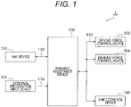
- An automatic parking system 1 chiefly includes a parking assistance device 100, a human machine interface (HMI) device 101 for display, an external recognition input device 102 including a camera, a sonar, a radar or the like, a driving force control device 103 including an engine, a motor or the like, a braking force control device 104 including a brake or the like, and a shift control device 106 for forward-backward switching.
- HMI human machine interface
- an external recognition input device 102 including a camera, a sonar, a radar or the like
- driving force control device 103 including an engine, a motor or the like
- a braking force control device 104 including a brake or the like
- shift control device 106 for forward-backward switching.
- the respective devices are related to each other such that information associated with the parking assistance device 100 is output to the HMI device 101, the driving force control device 103, the braking force control device 104, and the shift control device 106, and that information associated with the HMI device 101, the external recognition input device 102, the driving force control device 103, the braking force control device 104, and the shift control device 106 is output to the parking assistance device 100.
- outputs from the external recognition input device 102, the driving force control device 103, the braking force control device 104, and the shift control device 106 are input to an input unit 100i of the parking assistance device 100, and output to the driving force control device 103, the braking force control device 104, and the shift control device 106 via a computer 100c as a central processing unit and an output unit 100o.
- the parking assistance device 100 controls a vehicle speed of the corresponding vehicle during parking by controlling a driving force at the driving force control device 103 and a braking force at the braking force control device 104 based on these information.
- a current mode is a parking assistance mode based on the information associated with the parking start SW 101a (S301).
- parking assistance vehicle speed control is performed (S302).
- existing vehicle speed control is performed (S303).
- the control flow is programmed in the computer 100c of the parking assistance device 100, and repeatedly executed in a predetermined cycle.
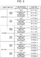
- a parking pattern PTNPA is acquired from the information obtained by the external recognition input device 102 and the like (see FIG. 5 for details) (S401). Thereafter, an actual vehicle speed Vsp is obtained from the information obtained by the vehicle speed input device 105 (S402). After a target vehicle speed TVsp is calculated (S403), a target driving force and a target braking force are calculated (S404). As shown in FIG. 5 , a plurality of patterns constituted by combinations of a parking method and a parking area adjoining obstacle are set for the parking pattern PTNPA. The parking pattern PTNPA is acquired based on these patterns.
- a target vehicle speed basic value TVspB is initially calculated (S601) as shown in a flowchart of FIG. 6 . Thereafter, a target vehicle speed upper limit TVspLMT is calculated (S602), and a target vehicle speed TVsp corresponding to the target vehicle speed basic value TVspB and the target vehicle speed upper limit TVspLMT is calculated (S603).
- a parking control traveling distance DistPA is first calculated (S701), and the target vehicle speed basic value TVspB is determined from the parking control traveling distance DistPA (S702).
- the relationship between the target vehicle speed basic value TVspB and the parking control travel distance DistPA is variable in accordance with the parking pattern PTNPA, as shown in FIG. 8 , for example.
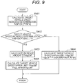
- a target vehicle speed increase determination fVSPIOK [PTNPA] is initially calculated (S901) as shown in the flowchart of FIG. 9 .
- an increase amount DTVspLMT is calculated (S903) .
- the target vehicle speed upper limit TVspLMT is corrected and set to such a value obtained by adding the increase amount DTVspLMT to the reference target vehicle speed upper limit TVspLMT obtained based on the parking pattern PTNPA, the information obtained from the shift control device 106, and others (S905).
- the reference target vehicle speed upper limit TVspLMT is retained (S904).
- the target vehicle speed increase determination fVSPIOK [PTNPA] it is initially determined whether or not a driver has stepped on the brake in previous parking (i.e., whether or not brake operation has been performed by the driver in previous parking) (S1001) to obtain a number of times of brake OFF continuous parking CTNAPBRKOF [PTNPA], which is a number of times of parking continuously performed without the brake operation (S1002).
- the number of times of brake OFF continuous parking CTNAPBRKOF [PTNPA] is set to 0 (S1003) when it is determined that the brake has been stepped on by the driver during previous parking (i.e., brake operation has been performed by the driver in previous parking).
- the number of times of the brake OFF continuous parking CTNAPBRKOF [PTNPA] herein is obtained for each of the parking patterns PTNPA.
- a target vehicle speed increase determination flag is set (i.e., the target vehicle speed increase determination fVSPIOK [PTNPA] is set to 1) (S1005).
- the number of times of brake OFF continuous parking CTNAPBRKOF [PTNPA] is reset (S1007), and the process finishes.
- the process finishes without setting the target vehicle speed increase determination flag (i.e., the target vehicle speed increase determination fVSPIOK [PTNPA] is set to 0) (S1006), and the process finishes without change.
- the threshold TH [PTNPA] described above is changed in accordance with the parking pattern PTNPA similarly to the number of times of brake OFF continuous parking CTNAPBRKOF [PTNPA].
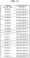
- the calculation process of the increase amount DTVspLMT shown in FIG. 9 (S903) that is, the calculation process of the increase amount DTVspLMT at the time of increase in the target vehicle speed TVsp will be next described with reference to FIG. 11 .
- the increase amount DTVspLMT is set in accordance with the parking pattern PTNPA.
- the increase amount DTVspLMT is appropriately determined using this map. Accordingly, an appropriate value of the target vehicle speed upper limit TVspLMT is calculated in the calculation process of the target vehicle speed basic value TVspB (S601).
- appropriate values of the target vehicle speed basic value TVspB and the target vehicle speed upper limit TVspLMT are calculated in the parking assistance vehicle speed control process (S302) shown in FIG. 3 , and an appropriate value of target vehicle speed TVsp corresponding to the parking pattern PTNPA and a behavior during parking is calculated based on the target vehicle speed basic value TVspB and the target vehicle speed upper limit TVspLMT.
- a part (A) in an uppermost stage shows parking assistance timing, while a part (B) shows a state of the brake SW at corresponding timing.
- a part (C) shows a part of times of brake OFF continuous parking CTNAPBRKOF [PTNPA] at subsequent parking assistance start timing t4.
- the target vehicle speed increase determination flag is set as shown in a part (D) (i.e., the target vehicle speed increase determination fVSPIOK [PTNPA] becomes 1).
- an upper limit vehicle speed (forward upper limit speed, backward upper limit speed) is increased and set as shown in a part (E).
- the vehicle speed of the corresponding vehicle during parking increases.
- the vehicle speed of the corresponding vehicle during parking generally increases.
- the manner of the increase in the vehicle speed of the corresponding vehicle during parking is not limited to this example.
- the forward upper limit speed and the backward upper limit speed may be individually set in an appropriate manner.
- the upper limit vehicle speed (target vehicle speed upper limit) is changed (increased and set) based on an experience of the automatic parking control even after the target vehicle speed of the vehicle is corrected to a lower speed at a start of use of the automatic parking control. In this manner, inconvenience felt by the driver experienced in the automatic parking control can be reduced by increasing the vehicle speed of the vehicle during parking.
- a parking assistance device according to a second embodiment of the present invention will be next described with reference to FIG. 13 .
- Described in the present second embodiment is another method of the target vehicle speed increase determination calculation shown in FIG. 10 in the first embodiment described above.
- Other configurations are similar to the corresponding configurations of the first embodiment, wherefore detailed description of these configurations will not be repeated.
- the target vehicle speed increase determination flag is set (i.e., the target vehicle speed increase determination fVSPIOK [PTNPA] is set to 1) (S1302).
- the target vehicle speed increase determination flag is not set (i.e., the target vehicle speed increase determination fVSPIOK [PTNPA] is set to 0) (S1303)
- the elapsed time TMRAPEXE [PTNPA] from previous parking, and the predetermined value ⁇ [PTNPA] for determination are herein set for each of the parking patterns PTNPA. More specifically, in the present second embodiment, it is considered that the driver is experienced in the automatic parking control when the elapsed time from previous parking is short. In this case, the upper limit vehicle speed (target vehicle speed upper limit) is raised to increase the vehicle speed of the corresponding vehicle during parking.
- a parking assistance device according to a third embodiment of the present invention will be next described with reference to FIG. 14 .
- Described in the present third embodiment is also another method of the target vehicle speed increase determination calculation shown in FIG. 10 in the first embodiment described above.
- Other configurations are similar to the corresponding configurations of the first embodiment, wherefore detailed description of these configurations will not be repeated.
- the target vehicle speed increase determination flag is set (i.e., the target vehicle speed increase determination fVSPIOK [PTNPA] is set to 1) (S1402).
- the target vehicle speed increase determination flag is not set (i.e., the target vehicle speed increase determination fVSPIOK [PTNPA] is set to 0) (S1403).
- the traveling distance DISAPEXE [PTNPA] from previous parking, and the predetermined value ⁇ [PTNPA] for determination are herein set for each of the parking patterns PTNPA. More specifically, according to the present third embodiment, it is considered that the driver is experienced in driving when the travel distance from previous parking is long. In this case, the upper limit vehicle speed (target vehicle speed upper limit) is raised to increase the vehicle speed of the corresponding vehicle during parking.
- a parking assistance device will be initially described with reference to FIG. 15 .
- the present fourth embodiment is another method of the target vehicle speed upper limit calculation shown in FIG. 9 of the first embodiment described above. This method is different chiefly in that on-off determination of the brake SW is added. Other configurations are similar to the corresponding configurations of the first embodiment, wherefore detailed description of these configurations will not be repeated.
- the on-off determination of the brake SW is made after a parking start to limit the upper limit of the vehicle speed (target vehicle speed upper limit) (i.e., correct the vehicle speed of the vehicle during parking to a lower speed) by the brake operation during parking, and then increase (return) the upper limit of the vehicle speed at the time of absence of the brake operation.
- target vehicle speed upper limit i.e., correct the vehicle speed of the vehicle during parking to a lower speed
- on-off of the brake SW after the parking start is determined (S1501).
- a brake on target vehicle speed upper limit TVspLMT is calculated to limit the upper limit of the vehicle speed by the brake operation during parking (S1506).
- a maximum speed reduction GMAX at that time is stored (S1507).
- the target vehicle speed increase determination fVSPIOK [PTNPA] is calculated (S1502).
- an increase amount DTVspLMT is calculated (S1504).
- the increase amount DTVspLMT of the target vehicle speed upper limit TVspLMT in the absence of the brake operation is corrected (changed) using a correction GAIN [GMAX] corresponding to the maximum speed reduction GMAX to reset the target vehicle speed upper limit TVspLMT (S1505).
- the correction GAIN is set to a value which decreases as the maximum speed reduction GMAX increases (i.e., decreases the increase amount DTVspLMT of the vehicle speed of the vehicle) to correct an increase amount of the target vehicle speed upper limit after sudden speed reduction to a small amount, and correct an increase amount of the target vehicle speed upper limit after slow speed reduction to a large amount.
- inconvenience felt by the driver experienced in automatic parking control after correction of the target vehicle speed of the vehicle to a lower speed at the start of automatic parking control is reduced by increasing the vehicle speed of the vehicle during parking in accordance with a behavior during parking of the vehicle or from previous parking, said behaviour being the brake operation by the driver. Further behaviours such as the elapsed time from previous parking, the traveling distance from previous parking, and speed reduction during parking may also be considered.
- the increase in the vehicle speed including the target vehicle speed upper limit is determined based on the vehicle behavior such as the brake operation by the driver, the elapsed time from previous parking, the traveling distance from previous parking, and speed reduction during parking. Needless to say, the increase in the vehicle speed including the target vehicle speed upper limit may be determined based on a vehicle behavior other than the above examples.
- a part or all of the configurations, functions, processing units, processing means and the like described above may be designed as integrated circuits to implement these by hardware.
- the respective configurations, functions and the like described above may be executed by a processor which interprets a program for achieving the respective functions to implement the functions by software.
- Information such as a program, a table, and a file for achieving the respective functions may be placed in a memory, a hard disk, a storage device such as a solid state drive (SSD), or a recording medium such as an IC card, an SD card, and a DVD.
- SSD solid state drive
- Control lines and information lines considered necessary for description are shown herein, and not all control lines and information lines provided in a product are necessarily shown. In practice, substantially all configurations may be considered to be mutually connected. Reference Signs List
Landscapes
- Engineering & Computer Science (AREA)
- Transportation (AREA)
- Mechanical Engineering (AREA)
- Automation & Control Theory (AREA)
- Physics & Mathematics (AREA)
- Mathematical Physics (AREA)
- Chemical & Material Sciences (AREA)
- Combustion & Propulsion (AREA)
- Control Of Driving Devices And Active Controlling Of Vehicle (AREA)
- Traffic Control Systems (AREA)
- Regulating Braking Force (AREA)
Description
- The present invention relates to a parking assistance device, and more particularly to a parking assistance device which controls a speed of a vehicle during parking of the vehicle in a parking space.
- A feeling of safety of a driver concerning a vehicle speed differs for each driver depending on an environment around the vehicle (presence or absence of obstacle), a driving experience of the driver, and others during automatic parking control for controlling acceleration, braking, steering and the like. As a conventional technology of this type, there is a known method which reduces a target vehicle speed of a vehicle during automatic parking in accordance with a distance between an obstacle and the vehicle at the time of input of a brake operation from a driver, as described in
JP 2016-150593 A -
EP 2 159 121 A1claim 1, discloses a parking assistance device according to the preamble ofclaim 1 in which an accelerator pedal can be used to increase a parking speed of the vehicle.US 2010/0036562 A1 relates to driver assistance systems which is adaptable in terms of its behavior based on an experience of the driver with the assistance system. - However, a feeling of anxiety concerning the vehicle speed decreases as the driver is more experienced in automatic parking. Accordingly, the driver may rather feel inconvenience when parking at a vehicle speed upper limit which is a corrected target vehicle speed to a lower speed in a manner described in
JP 2016-150593 A - The present invention has been developed in view of the aforementioned problems. It is an object of the present invention to provide a parking assistance device capable of reducing inconvenience felt by a driver experienced in automatic parking control during parking at a target vehicle speed corrected to a lower speed at a start of use of automatic parking control, for example.
- For solving the above problems, there is provided a parking assistance device for controlling a vehicle speed of a vehicle during parking to assist parking of the vehicle, wherein the vehicle speed of the vehicle during parking is increased in accordance with a behavior during parking or from previous parking of the vehicle. The vehicle speed of the vehicle during parking is increased based on presence or absence of a brake operation by a driver during previous parking and when parking is continuously performed a predetermined number of times without brake operation by the driver in a period until previous parking.
- According to the present invention, inconvenience felt by a driver experienced in automatic parking control can be reduced during parking at a target vehicle speed of a vehicle corrected to a lower speed at a start of use of automatic parking control, for example.
- Problems, configurations, and effects other than those described above will be apparent from following description of embodiments.
-
- [
FIG. 1] FIG. 1 is a diagram showing a schematic configuration of an automatic parking system including a parking assistance device according to a first embodiment of the present invention. - [
FIG. 2] FIG. 2 is a block diagram showing an input/output signal relationship of the parking assistance device, a driving force control device, a braking force control device, and a shift control device shown inFIG. 1 . - [
FIG. 3] FIG. 3 is a flowchart schematically showing overall control contents of a control method performed by the parking assistance device shown inFIG. 1 . - [
FIG. 4] FIG. 4 is a flowchart schematically showing a parking assistance vehicle speed control process shown inFIG. 3 . - [
FIG. 5] FIG. 5 is a table schematically showing a parking pattern acquisition process shown inFIG. 4 . - [
FIG. 6] FIG. 6 is a flowchart schematically showing a target vehicle speed calculation process shown inFIG. 4 . - [
FIG. 7] FIG. 7 is a flowchart schematically showing a target vehicle speed basic value calculation process shown inFIG. 6 . - [
FIG. 8] FIG. 8 is a calculation map for calculating a target vehicle speed basic value. - [
FIG. 9] FIG. 9 is a flowchart schematically showing a target vehicle speed upper limit calculation process shown inFIG. 6 . - [
FIG. 10] FIG. 10 is a flowchart schematically showing a target vehicle speed increase determination calculation process shown inFIG. 9 . - [
FIG. 11] FIG. 11 is a calculation map for calculating a target vehicle speed increase amount. - [
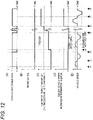
FIG. 12] FIG. 12 is a time chart showing an operation during vehicle parking performed by the parking assistance device shown inFIG. 1 . - [
FIG. 13] FIG. 13 is a flowchart schematically showing a target vehicle speed increase determination calculation process performed by a parking assistance device according to a second embodiment of the present invention. - [
FIG. 14] FIG. 14 is a flowchart schematically showing a target vehicle speed increase determination calculation process performed by a parking assistance device according to a third embodiment of the present invention. - [
FIG. 15] FIG. 15 is a flowchart schematically showing a target vehicle speed upper limit calculation process performed by a parking assistance device according to a fourth embodiment of the present invention. - Embodiments of the present invention will be hereinafter described with reference to the drawings.
- Each of the following embodiments to be described is divided into a plurality of sections or implementation examples as necessary for convenience. The respective sections and implementation examples are related to each other unless otherwise specified. One of the sections and implementation examples correspond a modified example, details, supplementary explanation and the like of a part or all of the others.
- A parking assistance device according to a first embodiment of the present invention will be initially described with reference to
FIGS. 1 to 12 . - A schematic configuration of an automatic parking system including a parking assistance device according to the first embodiment of the present invention will be first described with reference to
FIG. 1 . Anautomatic parking system 1 chiefly includes aparking assistance device 100, a human machine interface (HMI)device 101 for display, an externalrecognition input device 102 including a camera, a sonar, a radar or the like, a drivingforce control device 103 including an engine, a motor or the like, a brakingforce control device 104 including a brake or the like, and ashift control device 106 for forward-backward switching. These components are communicably connected to each other via a communication means 110 such as a controller area network (CAN). The respective devices are related to each other such that information associated with theparking assistance device 100 is output to theHMI device 101, the drivingforce control device 103, the brakingforce control device 104, and theshift control device 106, and that information associated with theHMI device 101, the externalrecognition input device 102, the drivingforce control device 103, the brakingforce control device 104, and theshift control device 106 is output to theparking assistance device 100. - Specifically, as shown in
FIG. 2 , outputs from the externalrecognition input device 102, the drivingforce control device 103, the brakingforce control device 104, and theshift control device 106 are input to aninput unit 100i of theparking assistance device 100, and output to the drivingforce control device 103, the brakingforce control device 104, and theshift control device 106 via acomputer 100c as a central processing unit and an output unit 100o. Note that not only detection information associated with a parking area, adjacent obstacles and the like and obtained by the externalrecognition input device 102, but also information associated with aparking start SW 101a for starting parking assistance, and information associated with a vehicle speed obtained from a vehiclespeed input device 105 such as a vehicle speed sensor are input to theinput unit 100i of theparking assistance device 100. Theparking assistance device 100 controls a vehicle speed of the corresponding vehicle during parking by controlling a driving force at the drivingforce control device 103 and a braking force at the brakingforce control device 104 based on these information. - An outline of entire vehicle speed control during vehicle parking performed by the
parking assistance device 100 shown inFIG. 1 will be next described with reference to a flowchart inFIG. 3 . - It is initially determined whether or not a current mode is a parking assistance mode based on the information associated with the parking start SW 101a (S301). When it is determined that the current mode is the parking assistance mode, parking assistance vehicle speed control is performed (S302). When it is determined that the current mode is not the parking assistance mode, existing vehicle speed control is performed (S303). The control flow is programmed in the
computer 100c of theparking assistance device 100, and repeatedly executed in a predetermined cycle. - An outline of a parking assistance vehicle speed control process (S302) shown in
FIG. 3 will be next described with reference to a flowchart inFIG. 4 . - In the parking assistance vehicle speed control process (S302), a parking pattern PTNPA is acquired from the information obtained by the external
recognition input device 102 and the like (seeFIG. 5 for details) (S401). Thereafter, an actual vehicle speed Vsp is obtained from the information obtained by the vehicle speed input device 105 (S402). After a target vehicle speed TVsp is calculated (S403), a target driving force and a target braking force are calculated (S404). As shown inFIG. 5 , a plurality of patterns constituted by combinations of a parking method and a parking area adjoining obstacle are set for the parking pattern PTNPA. The parking pattern PTNPA is acquired based on these patterns. - In a target vehicle speed calculation process (S403) shown in
FIG. 4 , a target vehicle speed basic value TVspB is initially calculated (S601) as shown in a flowchart ofFIG. 6 . Thereafter, a target vehicle speed upper limit TVspLMT is calculated (S602), and a target vehicle speed TVsp corresponding to the target vehicle speed basic value TVspB and the target vehicle speed upper limit TVspLMT is calculated (S603). - As shown in a flowchart in
FIG. 7 , in the calculation process (S601) of the target vehicle speed basic value TVspB, a parking control traveling distance DistPA is first calculated (S701), and the target vehicle speed basic value TVspB is determined from the parking control traveling distance DistPA (S702). The relationship between the target vehicle speed basic value TVspB and the parking control travel distance DistPA is variable in accordance with the parking pattern PTNPA, as shown inFIG. 8 , for example. - In the calculation process of the target vehicle speed upper limit TVspLMT (S602), a target vehicle speed increase determination fVSPIOK [PTNPA] is initially calculated (S901) as shown in the flowchart of
FIG. 9 . When it is determined that a target vehicle speed increase is necessary based on a result of the calculation (S902), an increase amount DTVspLMT is calculated (S903) . Thereafter, the target vehicle speed upper limit TVspLMT is corrected and set to such a value obtained by adding the increase amount DTVspLMT to the reference target vehicle speed upper limit TVspLMT obtained based on the parking pattern PTNPA, the information obtained from theshift control device 106, and others (S905). When NO in the target vehicle speed increase determination (S902), the reference target vehicle speed upper limit TVspLMT is retained (S904). - The calculation process (S901) of the target vehicle speed increase determination fVSPIOK [PTNPA] shown in
FIG. 9 will be more specifically described with reference to a flowchart inFIG. 10 . - In the calculation process (S901) of the target vehicle speed increase determination fVSPIOK [PTNPA], it is initially determined whether or not a driver has stepped on the brake in previous parking (i.e., whether or not brake operation has been performed by the driver in previous parking) (S1001) to obtain a number of times of brake OFF continuous parking CTNAPBRKOF [PTNPA], which is a number of times of parking continuously performed without the brake operation (S1002). Note that the number of times of brake OFF continuous parking CTNAPBRKOF [PTNPA] is set to 0 (S1003) when it is determined that the brake has been stepped on by the driver during previous parking (i.e., brake operation has been performed by the driver in previous parking). The number of times of the brake OFF continuous parking CTNAPBRKOF [PTNPA] herein is obtained for each of the parking patterns PTNPA. When the number of times of brake OFF continuous parking CTNAPBRKOF [PTNPA] exceeds a certain threshold TH [PTNPA] (i.e., when the driver continuously performs parking a predetermined number of times without the brake operation in a period until previous parking) (S1004), a target vehicle speed increase determination flag is set (i.e., the target vehicle speed increase determination fVSPIOK [PTNPA] is set to 1) (S1005). Thereafter, the number of times of brake OFF continuous parking CTNAPBRKOF [PTNPA] is reset (S1007), and the process finishes. In a case of no excess of the threshold TH [PTNPA] (S1004), the process finishes without setting the target vehicle speed increase determination flag (i.e., the target vehicle speed increase determination fVSPIOK [PTNPA] is set to 0) (S1006), and the process finishes without change. The threshold TH [PTNPA] described above is changed in accordance with the parking pattern PTNPA similarly to the number of times of brake OFF continuous parking CTNAPBRKOF [PTNPA].
- The calculation process of the increase amount DTVspLMT shown in
FIG. 9 (S903), that is, the calculation process of the increase amount DTVspLMT at the time of increase in the target vehicle speed TVsp will be next described with reference toFIG. 11 . As shown inFIG. 11 , the increase amount DTVspLMT is set in accordance with the parking pattern PTNPA. The increase amount DTVspLMT is appropriately determined using this map. Accordingly, an appropriate value of the target vehicle speed upper limit TVspLMT is calculated in the calculation process of the target vehicle speed basic value TVspB (S601). - By executing the above processes, appropriate values of the target vehicle speed basic value TVspB and the target vehicle speed upper limit TVspLMT are calculated in the parking assistance vehicle speed control process (S302) shown in
FIG. 3 , and an appropriate value of target vehicle speed TVsp corresponding to the parking pattern PTNPA and a behavior during parking is calculated based on the target vehicle speed basic value TVspB and the target vehicle speed upper limit TVspLMT. - An operation during vehicle parking performed by the
parking assistance device 100 shown inFIG. 1 will be next described with reference to a time chart inFIG. 12 . A part (A) in an uppermost stage shows parking assistance timing, while a part (B) shows a state of the brake SW at corresponding timing. When no brake operation is performed during a parking assistance period from t1 to t3, the number of times of brake OFF continuous parking CTNAPBRKOF [PTNPA] is counted up as shown in a part (C) at subsequent parking assistance start timing t4. Thereafter, at parking assistance t6 when the number of times of brake OFF continuous parking CTNAPBRKOF [PTNPA] exceeds the threshold TH [PTNPA], the target vehicle speed increase determination flag is set as shown in a part (D) (i.e., the target vehicle speed increase determination fVSPIOK [PTNPA] becomes 1). In this case, an upper limit vehicle speed (forward upper limit speed, backward upper limit speed) is increased and set as shown in a part (E). As a result, the vehicle speed of the corresponding vehicle during parking increases. In the example shown inFIG. 12 , the vehicle speed of the corresponding vehicle during parking generally increases. Needless to say, the manner of the increase in the vehicle speed of the corresponding vehicle during parking is not limited to this example. In addition, needless to say, the forward upper limit speed and the backward upper limit speed may be individually set in an appropriate manner. - According to the present embodiment, as described above, the upper limit vehicle speed (target vehicle speed upper limit) is changed (increased and set) based on an experience of the automatic parking control even after the target vehicle speed of the vehicle is corrected to a lower speed at a start of use of the automatic parking control. In this manner, inconvenience felt by the driver experienced in the automatic parking control can be reduced by increasing the vehicle speed of the vehicle during parking.
- A parking assistance device according to a second embodiment of the present invention will be next described with reference to
FIG. 13 . Described in the present second embodiment is another method of the target vehicle speed increase determination calculation shown inFIG. 10 in the first embodiment described above. Other configurations are similar to the corresponding configurations of the first embodiment, wherefore detailed description of these configurations will not be repeated. - As shown in
FIG. 13 , according to the present second embodiment, it is determined whether or not an elapsed time TMRAPEXE [PTNPA] from previous parking is shorter than a certain predetermined value α [PTNPA] (S1301). When it is determined that the elapsed time TMRAPEXE [PTNPA] is shorter than the predetermined value α [PTNPA], the target vehicle speed increase determination flag is set (i.e., the target vehicle speed increase determination fVSPIOK [PTNPA] is set to 1) (S1302). When it is determined that the elapsed time TMRAPEXE [PTNPA] is equal to or longer than the predetermined value α [PTNPA], the target vehicle speed increase determination flag is not set (i.e., the target vehicle speed increase determination fVSPIOK [PTNPA] is set to 0) (S1303) Note that the elapsed time TMRAPEXE [PTNPA] from previous parking, and the predetermined value α [PTNPA] for determination are herein set for each of the parking patterns PTNPA. More specifically, in the present second embodiment, it is considered that the driver is experienced in the automatic parking control when the elapsed time from previous parking is short. In this case, the upper limit vehicle speed (target vehicle speed upper limit) is raised to increase the vehicle speed of the corresponding vehicle during parking. - In this manner, inconvenience felt by the driver can be reduced similarly to the first embodiment.
- A parking assistance device according to a third embodiment of the present invention will be next described with reference to
FIG. 14 . Described in the present third embodiment is also another method of the target vehicle speed increase determination calculation shown inFIG. 10 in the first embodiment described above. Other configurations are similar to the corresponding configurations of the first embodiment, wherefore detailed description of these configurations will not be repeated. - As shown in
FIG. 14 , according to the present third embodiment, it is determined whether or not a traveling distance DISAPEXE [PTNPA] from previous parking is longer than a predetermined value β [PTNPA] (S1401). When it is determined that the traveling distance DISAPEXE [PTNPA] is longer than the predetermined value β [PTNPA], the target vehicle speed increase determination flag is set (i.e., the target vehicle speed increase determination fVSPIOK [PTNPA] is set to 1) (S1402). When it is determined that the traveling distance DISAPEXE [PTNPA] is equal to or shorter than the predetermined value β [PTNPA], the target vehicle speed increase determination flag is not set (i.e., the target vehicle speed increase determination fVSPIOK [PTNPA] is set to 0) (S1403). Note that the traveling distance DISAPEXE [PTNPA] from previous parking, and the predetermined value β [PTNPA] for determination are herein set for each of the parking patterns PTNPA. More specifically, according to the present third embodiment, it is considered that the driver is experienced in driving when the travel distance from previous parking is long. In this case, the upper limit vehicle speed (target vehicle speed upper limit) is raised to increase the vehicle speed of the corresponding vehicle during parking. - In this manner, inconvenience felt by the driver can be reduced similarly to the first embodiment.
- A parking assistance device according to a fourth embodiment of the present invention will be initially described with reference to
FIG. 15 . The present fourth embodiment is another method of the target vehicle speed upper limit calculation shown inFIG. 9 of the first embodiment described above. This method is different chiefly in that on-off determination of the brake SW is added. Other configurations are similar to the corresponding configurations of the first embodiment, wherefore detailed description of these configurations will not be repeated. - As shown in
FIG. 15 , according to the present fourth embodiment, the on-off determination of the brake SW is made after a parking start to limit the upper limit of the vehicle speed (target vehicle speed upper limit) (i.e., correct the vehicle speed of the vehicle during parking to a lower speed) by the brake operation during parking, and then increase (return) the upper limit of the vehicle speed at the time of absence of the brake operation. - Specifically, on-off of the brake SW after the parking start is determined (S1501). When it is determined that the brake SW is turned on, a brake on target vehicle speed upper limit TVspLMT is calculated to limit the upper limit of the vehicle speed by the brake operation during parking (S1506). In addition, a maximum speed reduction GMAX at that time is stored (S1507). On the other hand, when the brake SW is off, the target vehicle speed increase determination fVSPIOK [PTNPA] is calculated (S1502). When the target vehicle speed increase is required based on a result of the calculation (S1503), an increase amount DTVspLMT is calculated (S1504). Thereafter, the increase amount DTVspLMT of the target vehicle speed upper limit TVspLMT in the absence of the brake operation is corrected (changed) using a correction GAIN [GMAX] corresponding to the maximum speed reduction GMAX to reset the target vehicle speed upper limit TVspLMT (S1505). In this example, the correction GAIN is set to a value which decreases as the maximum speed reduction GMAX increases (i.e., decreases the increase amount DTVspLMT of the vehicle speed of the vehicle) to correct an increase amount of the target vehicle speed upper limit after sudden speed reduction to a small amount, and correct an increase amount of the target vehicle speed upper limit after slow speed reduction to a large amount.
- In this manner, inconvenience felt by the driver can be more precisely reduced.
- As described above, according to the invention, inconvenience felt by the driver experienced in automatic parking control after correction of the target vehicle speed of the vehicle to a lower speed at the start of automatic parking control is reduced by increasing the vehicle speed of the vehicle during parking in accordance with a behavior during parking of the vehicle or from previous parking, said behaviour being the brake operation by the driver. Further behaviours such as the elapsed time from previous parking, the traveling distance from previous parking, and speed reduction during parking may also be considered.
- In the first to fourth embodiments, the increase in the vehicle speed including the target vehicle speed upper limit is determined based on the vehicle behavior such as the brake operation by the driver, the elapsed time from previous parking, the traveling distance from previous parking, and speed reduction during parking. Needless to say, the increase in the vehicle speed including the target vehicle speed upper limit may be determined based on a vehicle behavior other than the above examples.
- A part or all of the configurations, functions, processing units, processing means and the like described above may be designed as integrated circuits to implement these by hardware. The respective configurations, functions and the like described above may be executed by a processor which interprets a program for achieving the respective functions to implement the functions by software. Information such as a program, a table, and a file for achieving the respective functions may be placed in a memory, a hard disk, a storage device such as a solid state drive (SSD), or a recording medium such as an IC card, an SD card, and a DVD.
- Control lines and information lines considered necessary for description are shown herein, and not all control lines and information lines provided in a product are necessarily shown. In practice, substantially all configurations may be considered to be mutually connected. Reference Signs List
-
- 1
- automatic parking system
- 100
- parking assistance device
- 100i
- input unit
- 100c
- computer
- 100o
- output unit
- 101
- HMI device
- 101a
- parking start SW
- 102
- external recognition input device
- 103
- driving force control device
- 104
- braking force control device
- 105
- vehicle speed input device
- 106
- shift control device
- 110
- communication means
Claims (11)
- A parking assistance device (100) that controls a vehicle speed of a vehicle during parking to assist parking of the vehicle,wherein the vehicle speed of the vehicle during parking is increased in accordance with a behavior during parking or from previous parking of the vehicle,characterized in that the vehicle speed of the vehicle during parking is increased based on presence or absence of a brake operation by a driver during previous parking and when parking is continuously performed a predetermined number of times without brake operation by the driver in a period until previous parking.
- The parking assistance device (100) according to claim 1, characterized in that a target vehicle speed upper limit (TVspLMT) of the vehicle speed of the vehicle during parking is increased and set in accordance with the behavior during parking or from previous parking of the vehicle.
- The parking assistance device (100) according to claim 1, characterized in that the predetermined number of times is changed in accordance with a parking pattern (PTNPA) .
- The parking assistance device (100) according to claim 1, characterized in that the vehicle speed of the vehicle during parking is increased based on an elapsed time (TMRAPEXE) from previous parking.
- The parking assistance device (100) according to claim 4, characterized in that the vehicle speed of the vehicle during parking is increased when the elapsed time (TMRAPEXE) from previous parking is shorter than a predetermined value (α).
- The parking assistance device (100) according to claim 1, characterized in that the vehicle speed of the vehicle during parking is increased based on a traveling distance (DISAPEXE) from previous parking.
- The parking assistance device (100) according to claim 6, characterized in that the vehicle speed of the vehicle during parking is increased when the traveling distance (DISAPEXE) from previous parking is longer than a predetermined value (β).
- The parking assistance device (100) according to claim 1, characterized in that an increase amount (DTVspLMT) of the vehicle speed of the vehicle is changed according to a parking pattern (PTNPA).
- The parking assistance device (100) according to claim 1, characterized in that the vehicle speed of the vehicle during parking is increased in accordance with a behavior during parking or from previous parking of the vehicle in a case where the vehicle speed of the vehicle during parking has been corrected to a lower speed.
- The parking assistance device (100) according to claim 1, characterized in that an increase amount (DTVspLMT) of the vehicle speed of the vehicle is changed in accordance with speed reduction during previous parking.
- The parking assistance device (100) according to claim 10, characterized in that the increase amount (DTVspLMT) of the vehicle speed of the vehicle is reduced as the speed reduction during previous parking increases.
Applications Claiming Priority (2)
| Application Number | Priority Date | Filing Date | Title |
|---|---|---|---|
| JP2017118907 | 2017-06-16 | ||
| PCT/JP2018/016923 WO2018230175A1 (en) | 2017-06-16 | 2018-04-26 | Parking assistance device |
Publications (3)
| Publication Number | Publication Date |
|---|---|
| EP3597499A1 EP3597499A1 (en) | 2020-01-22 |
| EP3597499A4 EP3597499A4 (en) | 2020-12-23 |
| EP3597499B1 true EP3597499B1 (en) | 2023-01-18 |
Family
ID=64660967
Family Applications (1)
| Application Number | Title | Priority Date | Filing Date |
|---|---|---|---|
| EP18817660.6A Active EP3597499B1 (en) | 2017-06-16 | 2018-04-26 | Parking assistance device |
Country Status (4)
| Country | Link |
|---|---|
| US (1) | US11173896B2 (en) |
| EP (1) | EP3597499B1 (en) |
| JP (1) | JP6838255B2 (en) |
| WO (1) | WO2018230175A1 (en) |
Families Citing this family (5)
| Publication number | Priority date | Publication date | Assignee | Title |
|---|---|---|---|---|
| CN109969171A (en) * | 2017-12-26 | 2019-07-05 | 罗伯特·博世有限公司 | Garage mode controlling unit, control system and control method |
| JP2020164065A (en) * | 2019-03-29 | 2020-10-08 | パナソニックIpマネジメント株式会社 | Vehicle control device, vehicle, vehicle control method, and vehicle control program |
| CN111806430B (en) * | 2020-06-03 | 2021-12-31 | 惠州市德赛西威汽车电子股份有限公司 | Vehicle speed calculation method for automatic parking |
| CN112026753B (en) * | 2020-08-27 | 2022-01-07 | 重庆长安汽车股份有限公司 | Method for controlling stable vehicle speed in low-speed scene |
| CN115214726B (en) * | 2021-04-19 | 2025-05-13 | 比亚迪股份有限公司 | Vehicle parking control method and device |
Family Cites Families (6)
| Publication number | Priority date | Publication date | Assignee | Title |
|---|---|---|---|---|
| DE102006039583A1 (en) * | 2006-08-23 | 2008-03-06 | Robert Bosch Gmbh | Driver assistance system |
| DE102008041681A1 (en) | 2008-08-29 | 2010-03-04 | Robert Bosch Gmbh | Control device and method for performing an automatic parking operation |
| JP5835566B2 (en) * | 2011-10-12 | 2015-12-24 | 株式会社デンソー | Parking assistance device |
| JP2014024462A (en) * | 2012-07-27 | 2014-02-06 | Nissan Motor Co Ltd | Parking support device |
| US10293816B2 (en) * | 2014-09-10 | 2019-05-21 | Ford Global Technologies, Llc | Automatic park and reminder system and method of use |
| JP2016150593A (en) | 2015-02-16 | 2016-08-22 | 三菱電機株式会社 | Vehicle control device and vehicle control device |
-
2018
- 2018-04-26 EP EP18817660.6A patent/EP3597499B1/en active Active
- 2018-04-26 JP JP2019525182A patent/JP6838255B2/en active Active
- 2018-04-26 WO PCT/JP2018/016923 patent/WO2018230175A1/en not_active Ceased
- 2018-04-26 US US16/622,148 patent/US11173896B2/en active Active
Also Published As
| Publication number | Publication date |
|---|---|
| WO2018230175A1 (en) | 2018-12-20 |
| US20200122718A1 (en) | 2020-04-23 |
| JP6838255B2 (en) | 2021-03-03 |
| EP3597499A1 (en) | 2020-01-22 |
| US11173896B2 (en) | 2021-11-16 |
| JPWO2018230175A1 (en) | 2020-03-19 |
| EP3597499A4 (en) | 2020-12-23 |
Similar Documents
| Publication | Publication Date | Title |
|---|---|---|
| EP3597499B1 (en) | Parking assistance device | |
| JP7213909B2 (en) | vehicle controller | |
| EP2845779B1 (en) | Driving assistance technique for active vehicle control | |
| US20190377352A1 (en) | Method and system for assisting an operator of an ego-vehicle in controlling the ego-vehicle by determining a future behavior and an associated trajectory for the ego-vehicle | |
| CN105882747A (en) | System and method for parallel parking a vehicle | |
| US20140297115A1 (en) | System and method for controlling vehicle driving mode | |
| US20110190961A1 (en) | Driver assistance system and operator control concept therefor | |
| CN113613967B (en) | Parking assist device, vehicle, parking assist method and storage medium | |
| US10919542B2 (en) | Apparatus and method for providing a kinesthetic cue in a driving automation equipped vehicle | |
| CN109689450A (en) | Steering control system and method for controlling steering | |
| CN109311483B (en) | Method for assisting the driver | |
| CN118201830A (en) | Method for assisting a user of a vehicle in a lane change maneuver taking into account different areas in the vehicle's surroundings and driver assistance system for a vehicle | |
| EP3552915B1 (en) | Apparatus and method for providing safety strategy in vehicle | |
| CN118907089A (en) | Vehicle cruise control method, device, vehicle, storage medium and program product | |
| CN112824187A (en) | Driving assistance system, and deceleration control unit and method therefor | |
| JP6946495B2 (en) | Vehicle control device and vehicle control method | |
| JP6717012B2 (en) | Travel control device | |
| JP4946734B2 (en) | Travel plan generation system and travel plan generation apparatus | |
| US20190351898A1 (en) | Driving support apparatus | |
| US9403531B2 (en) | System and method of controlling vehicle using turning degree | |
| CN116872930A (en) | Vehicle slope assist method, device, vehicle and storage medium | |
| CN117222562A (en) | Method for operating a driver assistance system with use of an active suggestion function for longitudinal control of a vehicle, driver assistance system and vehicle | |
| CN115179937A (en) | Vehicle control device, system having the same, and method thereof | |
| CN116802101A (en) | Reminder method and device for vehicles | |
| US20250381960A1 (en) | Control device for vehicle, storage medium, and control method |
Legal Events
| Date | Code | Title | Description |
|---|---|---|---|
| STAA | Information on the status of an ep patent application or granted ep patent |
Free format text: STATUS: THE INTERNATIONAL PUBLICATION HAS BEEN MADE |
|
| PUAI | Public reference made under article 153(3) epc to a published international application that has entered the european phase |
Free format text: ORIGINAL CODE: 0009012 |
|
| STAA | Information on the status of an ep patent application or granted ep patent |
Free format text: STATUS: REQUEST FOR EXAMINATION WAS MADE |
|
| 17P | Request for examination filed |
Effective date: 20191016 |
|
| AK | Designated contracting states |
Kind code of ref document: A1 Designated state(s): AL AT BE BG CH CY CZ DE DK EE ES FI FR GB GR HR HU IE IS IT LI LT LU LV MC MK MT NL NO PL PT RO RS SE SI SK SM TR |
|
| AX | Request for extension of the european patent |
Extension state: BA ME |
|
| DAV | Request for validation of the european patent (deleted) | ||
| DAX | Request for extension of the european patent (deleted) | ||
| A4 | Supplementary search report drawn up and despatched |
Effective date: 20201125 |
|
| RIC1 | Information provided on ipc code assigned before grant |
Ipc: B60W 50/00 20060101ALI20201119BHEP Ipc: B60W 40/105 20120101ALI20201119BHEP Ipc: B60W 40/09 20120101ALI20201119BHEP Ipc: B62D 15/02 20060101ALI20201119BHEP Ipc: B60W 30/06 20060101AFI20201119BHEP Ipc: B60R 99/00 20090101ALI20201119BHEP Ipc: G08G 1/16 20060101ALI20201119BHEP |
|
| RAP3 | Party data changed (applicant data changed or rights of an application transferred) |
Owner name: HITACHI ASTEMO, LTD. |
|
| GRAP | Despatch of communication of intention to grant a patent |
Free format text: ORIGINAL CODE: EPIDOSNIGR1 |
|
| STAA | Information on the status of an ep patent application or granted ep patent |
Free format text: STATUS: GRANT OF PATENT IS INTENDED |
|
| INTG | Intention to grant announced |
Effective date: 20221019 |
|
| GRAS | Grant fee paid |
Free format text: ORIGINAL CODE: EPIDOSNIGR3 |
|
| GRAA | (expected) grant |
Free format text: ORIGINAL CODE: 0009210 |
|
| STAA | Information on the status of an ep patent application or granted ep patent |
Free format text: STATUS: THE PATENT HAS BEEN GRANTED |
|
| AK | Designated contracting states |
Kind code of ref document: B1 Designated state(s): AL AT BE BG CH CY CZ DE DK EE ES FI FR GB GR HR HU IE IS IT LI LT LU LV MC MK MT NL NO PL PT RO RS SE SI SK SM TR |
|
| REG | Reference to a national code |
Ref country code: GB Ref legal event code: FG4D |
|
| REG | Reference to a national code |
Ref country code: DE Ref legal event code: R096 Ref document number: 602018045574 Country of ref document: DE |
|
| REG | Reference to a national code |
Ref country code: CH Ref legal event code: EP |
|
| REG | Reference to a national code |
Ref country code: AT Ref legal event code: REF Ref document number: 1544520 Country of ref document: AT Kind code of ref document: T Effective date: 20230215 Ref country code: IE Ref legal event code: FG4D |
|
| REG | Reference to a national code |
Ref country code: LT Ref legal event code: MG9D |
|
| REG | Reference to a national code |
Ref country code: NL Ref legal event code: MP Effective date: 20230118 |
|
| REG | Reference to a national code |
Ref country code: AT Ref legal event code: MK05 Ref document number: 1544520 Country of ref document: AT Kind code of ref document: T Effective date: 20230118 |
|
| PG25 | Lapsed in a contracting state [announced via postgrant information from national office to epo] |
Ref country code: NL Free format text: LAPSE BECAUSE OF FAILURE TO SUBMIT A TRANSLATION OF THE DESCRIPTION OR TO PAY THE FEE WITHIN THE PRESCRIBED TIME-LIMIT Effective date: 20230118 |
|
| PG25 | Lapsed in a contracting state [announced via postgrant information from national office to epo] |
Ref country code: RS Free format text: LAPSE BECAUSE OF FAILURE TO SUBMIT A TRANSLATION OF THE DESCRIPTION OR TO PAY THE FEE WITHIN THE PRESCRIBED TIME-LIMIT Effective date: 20230118 Ref country code: PT Free format text: LAPSE BECAUSE OF FAILURE TO SUBMIT A TRANSLATION OF THE DESCRIPTION OR TO PAY THE FEE WITHIN THE PRESCRIBED TIME-LIMIT Effective date: 20230518 Ref country code: NO Free format text: LAPSE BECAUSE OF FAILURE TO SUBMIT A TRANSLATION OF THE DESCRIPTION OR TO PAY THE FEE WITHIN THE PRESCRIBED TIME-LIMIT Effective date: 20230418 Ref country code: LV Free format text: LAPSE BECAUSE OF FAILURE TO SUBMIT A TRANSLATION OF THE DESCRIPTION OR TO PAY THE FEE WITHIN THE PRESCRIBED TIME-LIMIT Effective date: 20230118 Ref country code: LT Free format text: LAPSE BECAUSE OF FAILURE TO SUBMIT A TRANSLATION OF THE DESCRIPTION OR TO PAY THE FEE WITHIN THE PRESCRIBED TIME-LIMIT Effective date: 20230118 Ref country code: HR Free format text: LAPSE BECAUSE OF FAILURE TO SUBMIT A TRANSLATION OF THE DESCRIPTION OR TO PAY THE FEE WITHIN THE PRESCRIBED TIME-LIMIT Effective date: 20230118 Ref country code: ES Free format text: LAPSE BECAUSE OF FAILURE TO SUBMIT A TRANSLATION OF THE DESCRIPTION OR TO PAY THE FEE WITHIN THE PRESCRIBED TIME-LIMIT Effective date: 20230118 Ref country code: AT Free format text: LAPSE BECAUSE OF FAILURE TO SUBMIT A TRANSLATION OF THE DESCRIPTION OR TO PAY THE FEE WITHIN THE PRESCRIBED TIME-LIMIT Effective date: 20230118 |
|
| PG25 | Lapsed in a contracting state [announced via postgrant information from national office to epo] |
Ref country code: SE Free format text: LAPSE BECAUSE OF FAILURE TO SUBMIT A TRANSLATION OF THE DESCRIPTION OR TO PAY THE FEE WITHIN THE PRESCRIBED TIME-LIMIT Effective date: 20230118 Ref country code: PL Free format text: LAPSE BECAUSE OF FAILURE TO SUBMIT A TRANSLATION OF THE DESCRIPTION OR TO PAY THE FEE WITHIN THE PRESCRIBED TIME-LIMIT Effective date: 20230118 Ref country code: IS Free format text: LAPSE BECAUSE OF FAILURE TO SUBMIT A TRANSLATION OF THE DESCRIPTION OR TO PAY THE FEE WITHIN THE PRESCRIBED TIME-LIMIT Effective date: 20230518 Ref country code: GR Free format text: LAPSE BECAUSE OF FAILURE TO SUBMIT A TRANSLATION OF THE DESCRIPTION OR TO PAY THE FEE WITHIN THE PRESCRIBED TIME-LIMIT Effective date: 20230419 Ref country code: FI Free format text: LAPSE BECAUSE OF FAILURE TO SUBMIT A TRANSLATION OF THE DESCRIPTION OR TO PAY THE FEE WITHIN THE PRESCRIBED TIME-LIMIT Effective date: 20230118 |
|
| REG | Reference to a national code |
Ref country code: DE Ref legal event code: R097 Ref document number: 602018045574 Country of ref document: DE |
|
| PG25 | Lapsed in a contracting state [announced via postgrant information from national office to epo] |
Ref country code: SM Free format text: LAPSE BECAUSE OF FAILURE TO SUBMIT A TRANSLATION OF THE DESCRIPTION OR TO PAY THE FEE WITHIN THE PRESCRIBED TIME-LIMIT Effective date: 20230118 Ref country code: RO Free format text: LAPSE BECAUSE OF FAILURE TO SUBMIT A TRANSLATION OF THE DESCRIPTION OR TO PAY THE FEE WITHIN THE PRESCRIBED TIME-LIMIT Effective date: 20230118 Ref country code: EE Free format text: LAPSE BECAUSE OF FAILURE TO SUBMIT A TRANSLATION OF THE DESCRIPTION OR TO PAY THE FEE WITHIN THE PRESCRIBED TIME-LIMIT Effective date: 20230118 Ref country code: DK Free format text: LAPSE BECAUSE OF FAILURE TO SUBMIT A TRANSLATION OF THE DESCRIPTION OR TO PAY THE FEE WITHIN THE PRESCRIBED TIME-LIMIT Effective date: 20230118 Ref country code: CZ Free format text: LAPSE BECAUSE OF FAILURE TO SUBMIT A TRANSLATION OF THE DESCRIPTION OR TO PAY THE FEE WITHIN THE PRESCRIBED TIME-LIMIT Effective date: 20230118 |
|
| PLBE | No opposition filed within time limit |
Free format text: ORIGINAL CODE: 0009261 |
|
| STAA | Information on the status of an ep patent application or granted ep patent |
Free format text: STATUS: NO OPPOSITION FILED WITHIN TIME LIMIT |
|
| PG25 | Lapsed in a contracting state [announced via postgrant information from national office to epo] |
Ref country code: SK Free format text: LAPSE BECAUSE OF FAILURE TO SUBMIT A TRANSLATION OF THE DESCRIPTION OR TO PAY THE FEE WITHIN THE PRESCRIBED TIME-LIMIT Effective date: 20230118 |
|
| REG | Reference to a national code |
Ref country code: CH Ref legal event code: PL |
|
| 26N | No opposition filed |
Effective date: 20231019 |
|
| GBPC | Gb: european patent ceased through non-payment of renewal fee |
Effective date: 20230426 |
|
| PG25 | Lapsed in a contracting state [announced via postgrant information from national office to epo] |
Ref country code: LU Free format text: LAPSE BECAUSE OF NON-PAYMENT OF DUE FEES Effective date: 20230426 |
|
| REG | Reference to a national code |
Ref country code: BE Ref legal event code: MM Effective date: 20230430 |
|
| PG25 | Lapsed in a contracting state [announced via postgrant information from national office to epo] |
Ref country code: MC Free format text: LAPSE BECAUSE OF FAILURE TO SUBMIT A TRANSLATION OF THE DESCRIPTION OR TO PAY THE FEE WITHIN THE PRESCRIBED TIME-LIMIT Effective date: 20230118 |
|
| PG25 | Lapsed in a contracting state [announced via postgrant information from national office to epo] |
Ref country code: GB Free format text: LAPSE BECAUSE OF NON-PAYMENT OF DUE FEES Effective date: 20230426 |
|
| PG25 | Lapsed in a contracting state [announced via postgrant information from national office to epo] |
Ref country code: SI Free format text: LAPSE BECAUSE OF FAILURE TO SUBMIT A TRANSLATION OF THE DESCRIPTION OR TO PAY THE FEE WITHIN THE PRESCRIBED TIME-LIMIT Effective date: 20230118 Ref country code: MC Free format text: LAPSE BECAUSE OF FAILURE TO SUBMIT A TRANSLATION OF THE DESCRIPTION OR TO PAY THE FEE WITHIN THE PRESCRIBED TIME-LIMIT Effective date: 20230118 Ref country code: LI Free format text: LAPSE BECAUSE OF NON-PAYMENT OF DUE FEES Effective date: 20230430 Ref country code: GB Free format text: LAPSE BECAUSE OF NON-PAYMENT OF DUE FEES Effective date: 20230426 Ref country code: FR Free format text: LAPSE BECAUSE OF NON-PAYMENT OF DUE FEES Effective date: 20230430 Ref country code: CH Free format text: LAPSE BECAUSE OF NON-PAYMENT OF DUE FEES Effective date: 20230430 |
|
| REG | Reference to a national code |
Ref country code: IE Ref legal event code: MM4A |
|
| PG25 | Lapsed in a contracting state [announced via postgrant information from national office to epo] |
Ref country code: BE Free format text: LAPSE BECAUSE OF NON-PAYMENT OF DUE FEES Effective date: 20230430 |
|
| PG25 | Lapsed in a contracting state [announced via postgrant information from national office to epo] |
Ref country code: IE Free format text: LAPSE BECAUSE OF NON-PAYMENT OF DUE FEES Effective date: 20230426 |
|
| PG25 | Lapsed in a contracting state [announced via postgrant information from national office to epo] |
Ref country code: IE Free format text: LAPSE BECAUSE OF NON-PAYMENT OF DUE FEES Effective date: 20230426 |
|
| PG25 | Lapsed in a contracting state [announced via postgrant information from national office to epo] |
Ref country code: IT Free format text: LAPSE BECAUSE OF FAILURE TO SUBMIT A TRANSLATION OF THE DESCRIPTION OR TO PAY THE FEE WITHIN THE PRESCRIBED TIME-LIMIT Effective date: 20230118 |
|
| PG25 | Lapsed in a contracting state [announced via postgrant information from national office to epo] |
Ref country code: BG Free format text: LAPSE BECAUSE OF FAILURE TO SUBMIT A TRANSLATION OF THE DESCRIPTION OR TO PAY THE FEE WITHIN THE PRESCRIBED TIME-LIMIT Effective date: 20230118 |
|
| PG25 | Lapsed in a contracting state [announced via postgrant information from national office to epo] |
Ref country code: BG Free format text: LAPSE BECAUSE OF FAILURE TO SUBMIT A TRANSLATION OF THE DESCRIPTION OR TO PAY THE FEE WITHIN THE PRESCRIBED TIME-LIMIT Effective date: 20230118 |
|
| PGFP | Annual fee paid to national office [announced via postgrant information from national office to epo] |
Ref country code: DE Payment date: 20250305 Year of fee payment: 8 |
|
| PG25 | Lapsed in a contracting state [announced via postgrant information from national office to epo] |
Ref country code: CY Free format text: LAPSE BECAUSE OF FAILURE TO SUBMIT A TRANSLATION OF THE DESCRIPTION OR TO PAY THE FEE WITHIN THE PRESCRIBED TIME-LIMIT; INVALID AB INITIO Effective date: 20180426 |
|
| PG25 | Lapsed in a contracting state [announced via postgrant information from national office to epo] |
Ref country code: HU Free format text: LAPSE BECAUSE OF FAILURE TO SUBMIT A TRANSLATION OF THE DESCRIPTION OR TO PAY THE FEE WITHIN THE PRESCRIBED TIME-LIMIT; INVALID AB INITIO Effective date: 20180426 |
|
| PG25 | Lapsed in a contracting state [announced via postgrant information from national office to epo] |
Ref country code: TR Free format text: LAPSE BECAUSE OF FAILURE TO SUBMIT A TRANSLATION OF THE DESCRIPTION OR TO PAY THE FEE WITHIN THE PRESCRIBED TIME-LIMIT Effective date: 20230118 |