EP3597487A1 - Adjustable holding assembly - Google Patents
Adjustable holding assembly Download PDFInfo
- Publication number
- EP3597487A1 EP3597487A1 EP19186294.5A EP19186294A EP3597487A1 EP 3597487 A1 EP3597487 A1 EP 3597487A1 EP 19186294 A EP19186294 A EP 19186294A EP 3597487 A1 EP3597487 A1 EP 3597487A1
- Authority
- EP
- European Patent Office
- Prior art keywords
- base
- flexible connector
- channel
- electrical harness
- mounting assembly
- Prior art date
- Legal status (The legal status is an assumption and is not a legal conclusion. Google has not performed a legal analysis and makes no representation as to the accuracy of the status listed.)
- Granted
Links
Images




Classifications
-
- B—PERFORMING OPERATIONS; TRANSPORTING
- B60—VEHICLES IN GENERAL
- B60R—VEHICLES, VEHICLE FITTINGS, OR VEHICLE PARTS, NOT OTHERWISE PROVIDED FOR
- B60R16/00—Electric or fluid circuits specially adapted for vehicles and not otherwise provided for; Arrangement of elements of electric or fluid circuits specially adapted for vehicles and not otherwise provided for
- B60R16/02—Electric or fluid circuits specially adapted for vehicles and not otherwise provided for; Arrangement of elements of electric or fluid circuits specially adapted for vehicles and not otherwise provided for electric constitutive elements
- B60R16/0207—Wire harnesses
- B60R16/0215—Protecting, fastening and routing means therefor
-
- F—MECHANICAL ENGINEERING; LIGHTING; HEATING; WEAPONS; BLASTING
- F16—ENGINEERING ELEMENTS AND UNITS; GENERAL MEASURES FOR PRODUCING AND MAINTAINING EFFECTIVE FUNCTIONING OF MACHINES OR INSTALLATIONS; THERMAL INSULATION IN GENERAL
- F16L—PIPES; JOINTS OR FITTINGS FOR PIPES; SUPPORTS FOR PIPES, CABLES OR PROTECTIVE TUBING; MEANS FOR THERMAL INSULATION IN GENERAL
- F16L3/00—Supports for pipes, cables or protective tubing, e.g. hangers, holders, clamps, cleats, clips, brackets
- F16L3/08—Supports for pipes, cables or protective tubing, e.g. hangers, holders, clamps, cleats, clips, brackets substantially surrounding the pipe, cable or protective tubing
- F16L3/12—Supports for pipes, cables or protective tubing, e.g. hangers, holders, clamps, cleats, clips, brackets substantially surrounding the pipe, cable or protective tubing comprising a member substantially surrounding the pipe, cable or protective tubing
- F16L3/123—Supports for pipes, cables or protective tubing, e.g. hangers, holders, clamps, cleats, clips, brackets substantially surrounding the pipe, cable or protective tubing comprising a member substantially surrounding the pipe, cable or protective tubing and extending along the attachment surface
-
- F—MECHANICAL ENGINEERING; LIGHTING; HEATING; WEAPONS; BLASTING
- F01—MACHINES OR ENGINES IN GENERAL; ENGINE PLANTS IN GENERAL; STEAM ENGINES
- F01D—NON-POSITIVE DISPLACEMENT MACHINES OR ENGINES, e.g. STEAM TURBINES
- F01D25/00—Component parts, details, or accessories, not provided for in, or of interest apart from, other groups
- F01D25/28—Supporting or mounting arrangements, e.g. for turbine casing
-
- H—ELECTRICITY
- H02—GENERATION; CONVERSION OR DISTRIBUTION OF ELECTRIC POWER
- H02G—INSTALLATION OF ELECTRIC CABLES OR LINES, OR OF COMBINED OPTICAL AND ELECTRIC CABLES OR LINES
- H02G3/00—Installations of electric cables or lines or protective tubing therefor in or on buildings, equivalent structures or vehicles
- H02G3/30—Installations of cables or lines on walls, floors or ceilings
- H02G3/32—Installations of cables or lines on walls, floors or ceilings using mounting clamps
-
- B—PERFORMING OPERATIONS; TRANSPORTING
- B64—AIRCRAFT; AVIATION; COSMONAUTICS
- B64C—AEROPLANES; HELICOPTERS
- B64C1/00—Fuselages; Constructional features common to fuselages, wings, stabilising surfaces or the like
- B64C1/40—Sound or heat insulation, e.g. using insulation blankets
- B64C1/403—Arrangement of fasteners specially adapted therefor, e.g. of clips
- B64C1/406—Arrangement of fasteners specially adapted therefor, e.g. of clips in combination with supports for lines, e.g. for pipes or cables
Definitions
- Embodiments of the present disclosure pertain to the art of fasteners, and more specifically, to a fastener for use with an electrical harness of an engine.
- At least one electric cable assembly Positioned about the external surface of an engine is at least one electric cable assembly, commonly referred to as an electrical harness.
- electrical harnesses are used to supply electricity to various pieces of peripheral equipment of the engine, such as sensors, computer controls and actuators for example.
- Each electrical harness is handmade and has a diameter and stiffness based on a given application of the harness. Accordingly, there is commonly significant variation between harnesses within a single engine.
- Each engine harness is generally held in place by supports, brackets, and spring clips spaced at intervals over the length of the harness.
- a spring clip is hard mounted to a custom mounting bracket for attachment to the harness.
- changes in position or size cannot be accommodated without a complete redesign. Accordingly, there is a need for an assembly for mounting an electrical harness that can be easily adapted for use with various configurations of an electrical harness and engine.
- a mounting assembly for restricting movement of an electrical harness of a gas turbine engine including a base, a first channel formed in the base and extending between a first surface and a second surface of the base, and a second channel formed in the base and extending between the first surface and a third surface of the base.
- the second surface and the third surface are distinct.
- At least one flexible connector is receivable within the first channel and the second channel. At least a portion of the at least one flexible connector extends about the electrical harness to couple the electrical harness to the base.
- the first channel is located adjacent a first side of the base and the second channel is positioned adjacent a second side of the base.
- the first channel extends from an upper surface of the base to a first side surface of the base and the second channel extends from the upper surface of the base to a second side surface of the base.
- the first side surface is disposed opposite the second side surface.
- the at least one flexible connector includes a first end and a second end, at least one of the first end and the second end being affixed within one of the first channel and the second channel.
- the at least one flexible connector includes a single flexible connector, the first end of the single flexible connector being affixed within the first channel and the second end of the single flexible connector being affixed within the second channel.
- the at least one flexible connector includes a first flexible connector and a second flexible connector, a first end of the first flexible connector being affixed within the first channel and a first end of the second flexible connector being affixed within the second channel.
- a second end of the first flexible connector is coupleable to a second end of the second flexible connector to couple the electrical harness to the base.
- the second end of the first connector is coupleable to the second end of the second flexible connector via a hook and loop-type attachment.
- a tab is formed at a second end of at least one of the first flexible connector and the second flexible connector.
- the at least one flexible connector includes a single flexible connector having a first end and a second end, the first end being extendable through the first channel and the second end being extendable through the second channel.
- the first end is connectable to the second end to couple the electrical harness to the base.
- the first end is coupleable to the second end via a hook and loop-type attachment.
- a force applied by the at least one connector to the electrical harness is adjustable.
- a gas turbine engine comprising: a mounting surface; an electrical harness; and the mounting assembly of any preceding claim, wherein the base is connected to the mounting surface.
- the mounting assembly may be for affixing the electrical harness to the mounting surface at a location.
- a gas turbine engine including a mounting surface, an electrical harness, and a mounting assembly for affixing the electrical harness to the mounting surface at a location.
- the mounting assembly includes a base connected to the mounting surface, a first channel formed in the base and extending between a first surface and a second surface of the base, and a second channel formed in the base and extending between the first surface and a third surface of the base.
- the second surface and the third surface are distinct.
- At least one flexible connector is receivable within the first channel and the second channel and at least a portion of the at least one flexible connector extends about the electrical harness to couple the electrical harness to the base.
- the mounting assembly may be a mounting assembly as recited herein with reference to the first aspect of the invention.
- the engine of the second and/or third aspect of the invention further comprises a casing and the mounting surface is an exterior surface of the casing.
- the engine of the second and/or third aspect of the invention is an aircraft engine.
- a method of restricting movement of an electrical harness relative to a gas turbine engine including positioning the electrical harness in contact with a base of a mounting assembly and wrapping at least one flexible connector about the electrical harness.
- the at least one flexible connector extends through a first channel and a second channel formed in the base.
- the first channel is formed between a first surface and a second surface of the base and the second channel is formed between a first surface and a third surface of the base.
- the second surface and the third surface are distinct.
- the method additionally includes restricting movement of the at least one flexible connector relative to the base.
- the at least one flexible connector includes affixing a first end of the at least one flexible connector to a second end of the at least one flexible connector.
- restricting movement of the at least one flexible connector relative to the base includes affixing an end of the at least one flexible connector to the base.
- the method may comprise using a mounting assembly as described herein with reference to the first aspect of the invention.
- the gas turbine engine may be a gas turbine engine as described herein with reference to the second and/or third aspect of the invention.
- FIG. 1 schematically illustrates a gas turbine engine 20.
- the gas turbine engine 20 is disclosed herein as a two-spool turbofan that generally incorporates a fan section 22, a compressor section 24, a combustor section 26 and a turbine section 28.
- Alternative engines might include other systems or features.
- the fan section 22 drives air along a bypass flow path B in a bypass duct, while the compressor section 24 drives air along a core flow path C for compression and communication into the combustor section 26 then expansion through the turbine section 28.
- FIG. 1 schematically illustrates a gas turbine engine 20.
- the gas turbine engine 20 is disclosed herein as a two-spool turbofan that generally incorporates a fan section 22, a compressor section 24, a combustor section 26 and a turbine section 28.
- Alternative engines might include other systems or features.
- the fan section 22 drives air along a bypass flow path B in a bypass duct
- the compressor section 24 drives air along a core flow path C for compression and communication into the combustor section 26
- the exemplary engine 20 generally includes a low speed spool 30 and a high speed spool 32 mounted for rotation about an engine central longitudinal axis A relative to an engine static structure 36 via several bearing systems 38. It should be understood that various bearing systems 38 at various locations may alternatively or additionally be provided, and the location of bearing systems 38 may be varied as appropriate to the application.
- the low speed spool 30 generally includes an inner shaft 40 that interconnects a fan 42, a low pressure compressor 44 and a low pressure turbine 46.
- the inner shaft 40 is connected to the fan 42 through a speed change mechanism, which in exemplary gas turbine engine 20 is illustrated as a geared architecture 48 to drive the fan 42 at a lower speed than the low speed spool 30.
- the high speed spool 32 includes an outer shaft 50 that interconnects a high pressure compressor 52 and high pressure turbine 54.
- a combustor 56 is arranged in exemplary gas turbine 20 between the high pressure compressor 52 and the high pressure turbine 54.
- An engine static structure 36 is arranged generally between the high pressure turbine 54 and the low pressure turbine 46.
- the engine static structure 36 further supports bearing systems 38 in the turbine section 28.
- the inner shaft 40 and the outer shaft 50 are concentric and rotate via bearing systems 38 about the engine central longitudinal axis A which is collinear with their longitudinal axes.
- each of the positions of the fan section 22, compressor section 24, combustor section 26, turbine section 28, and fan drive gear system 48 may be varied.
- gear system 48 may be located aft of combustor section 26 or even aft of turbine section 28, and fan section 22 may be positioned forward or aft of the location of gear system 48.
- the engine 20 in one example is a high-bypass geared aircraft engine.
- the engine 20 bypass ratio is greater than about six (6), with an example embodiment being greater than about ten (10)
- the geared architecture 48 is an epicyclic gear train, such as a planetary gear system or other gear system, with a gear reduction ratio of greater than about 2.3
- the low pressure turbine 46 has a pressure ratio that is greater than about five.
- the engine 20 bypass ratio is greater than about ten (10:1)
- the fan diameter is significantly larger than that of the low pressure compressor 44
- the low pressure turbine 46 has a pressure ratio that is greater than about five 5:1.
- Low pressure turbine 46 pressure ratio is pressure measured prior to inlet of low pressure turbine 46 as related to the pressure at the outlet of the low pressure turbine 46 prior to an exhaust nozzle.
- the geared architecture 48 may be an epicycle gear train, such as a planetary gear system or other gear system, with a gear reduction ratio of greater than about 2.3:1. It should be understood, however, that the above parameters are only exemplary of one embodiment of a geared architecture engine and that the present disclosure is applicable to other gas turbine engines including direct drive turbofans.
- the fan section 22 of the engine 20 is designed for a particular flight condition--typically cruise at about 0.8Mach and about 35,000 feet (10,688 meters).
- 'TSFC' Thrust Specific Fuel Consumption
- Low fan pressure ratio is the pressure ratio across the fan blade alone, without a Fan Exit Guide Vane (“FEGV”) system.
- the low fan pressure ratio as disclosed herein according to one non-limiting embodiment is less than about 1.45.
- Low corrected fan tip speed is the actual fan tip speed in ft/sec divided by an industry standard temperature correction of [(Tram °R)/(518.7 °R)] 0.5 .
- the "Low corrected fan tip speed” as disclosed herein according to one non-limiting embodiment is less than about 1150 ft/second (350.5 m/sec).
- one or more electrical harnesses 60 are typically laid about the periphery of an exterior of a casing or housing of the engine 20. These electrical harnesses 60 are configured to supply power to the various portions of the engine 20 or to electrical components or subsystems associated therewith. These harnesses 60 are typically held in place by one or more mounting assemblies 70 disposed at various locations along the length of the electrical harness 60 and engine 20.
- the mounting assembly 70 includes a base 72 and one or more flexible connectors 86, such as straps for example, configured to cooperate with the base 72 to restrict movement of an electrical harness 60 relative to the mounting assembly 70.
- the material used to form the base 72 may be selected based on the environment of the engine 20 and one or more requirements associated with the specific area within which the mounting assembly 70 is located.
- the base 72 may be formed from any suitable material including, but not limited to Teflon, PEEK, and metal for example. In embodiments where the base 72 is formed from a plastic material, the base 72 may be injection molded.
- the base 72 of the mounting assembly 70 is generally rectangular in shape and has a generally rectangular cross-section taken along either a first axis X, or a second axis Y, oriented substantially perpendicular to the first axis X and generally parallel to an axis defined by the electrical harness 60.
- a base 72 having another shape is also considered within the scope of the disclosure.
- One or more channels 74 may be formed in the base 72.
- a first channel 74a is located adjacent a first side of the base 72 and a second channel 74b is located adjacent a second, opposite side of the base 72.
- each of the first and second channels 74a, 74b extends from an upper surface 76 of the base 72 to either the first or second side surface 78, 80 of the base 72, respectively.
- the first channel 74a and the second channel 74b are illustrated as being aligned, in other embodiments, the first channel 74a and the second channel 74b may be axially offset from one another about at least one of the first and second axis X, Y.
- the one or more channels 74 illustrated and described herein are intended as an example only, and that a base of a mounting assembly 70 having any suitable number of channels 74 having any size, shape, and location are within the scope of the disclosure.
- the base 72 includes a portion 82 located vertically upward of the one or more channels 74.
- This portion 82 may be referred to herein as a cover and cooperates with the remainder of the base 72 to define at least a portion of the channel 74.
- the upper surface 84 of the cover 82 may be generally flush with the upper surface 76 of the remainder of the base 72.
- the base 72 may include a first cover 82a disposed upwardly adjacent the first channel 74a and a second cover 82b disposed upwardly adjacent the second channel 74b. As best shown in FIGS.
- the one or more covers 82a, 82b may be movable relative to the remainder of the base 72, or in some embodiments removable from the remainder of the base 72, to provide access to a corresponding channel 74a, 74b.
- the one or more covers 82a, 82b may be affixed to or integrally formed with the base 72, as shown in FIG. 6 .
- the base 72 need not include a cover 82 arranged vertically above the channel 74. In such embodiments, an upper surface of the channel 74 is not defined.
- the mounting assembly 70 additionally includes one or more flexible connectors or straps 86 configured to wrap at least partially about the circumference of the electrical harness 60 to secure the electrical harness 60 to the base 72.
- An example of a flexible connector 86 is illustrated in more detail in FIG. 7 .
- the flexible connector 86 shown includes a first end 88 receivable within a corresponding channel formed in the base 72.
- a mounting hole 89 may be formed in the flexible connector 86 near the first end 88 such that when the first end 88 is installed within a corresponding channel 74 of the base 72, a fastener 90 may extend through the base 72 and the mounting hole 89 to couple the flexible connector 86 to the base 72.
- a protrusion 92 may extend from second end 94 of the flexible connector 86 at an angle, such as perpendicular for example, to the body of the flexible connector 86.
- the flexible connector 86 may be formed from any suitable non-rigid material.
- the flexible connector 86 may be formed from PEEK, TEFZEL, Teflon, Metal, or any other suitable material that meets the engine requirements at a given location.
- the flexible connector 86 may be formed form an encapsulated material.
- the assembly 70 includes a first flexible connector 86a associated with the first channel 74a and a second flexible connector 86b associated with the second channel 74b.
- first end 88a of the first flexible connector 86a is arranged within the first channel 74a and secured to the base 72 by a first fastener 90 and a first end 88b of the second flexible connector 86b is arranged within the second channel 74b and secured to the base 72 by a second fastener 90.
- a fastener such as a screw or bolt is shown, it should be understood that any suitable connector or fastening mechanism may be used to retain the first ends 88a, 88b of the flexible connector 86a, 86b relative to the base 72.
- the free second end 94a, 94b of the first flexible connector 86a and the second flexible connector 86b are positionable about an exterior surface of the electrical harness 60.
- the first flexible connector 86a and the second flexible connector 86b extend at an angle to the axis of the harness 60.
- the straps 86a, 86b are elongated such that the second ends 94a, 94b of the flexible connectors 86a, 86b are configured to overlap one another about the body of the electrical harness 60.
- the straps 86a, 86b may be configured to affix or couple to one another, as shown in FIG. 5 , such as via Velcro, a hook and loop fastening system, or any other suitable connection mechanism.
- each flexible connector 86a, 86b allows a user to easily maneuver and apply a desired force to the flexible connector 86a, 86b to secure the harness 60 to the module assembly70.
- each flexible connector 86a, 86b may be configured to couple to an opposite side of the base 72, such that the first end 88a, 88b of each flexible connector 86a, 86b is connected to the base 72 adjacent a first side of the electrical harness 60 and a second end 92a, 92b of the flexible connector 86a, 86b is coupled to the base 72 adjacent a second, opposite side of the electrical harness 60.
- any suitable connection mechanism (not shown) may used to secure the free second end of each flexible connector 86 to the base 72.
- the mounting assembly 70 includes a single flexible connector 86.
- the flexible connector 86 may, but need not include one or more mounting holes 89 and a protrusion 92 located at either end 88, 94 thereof.
- a portion of the flexible connector 86 may wrap about a lower surface 96 of the base 72.
- the single strap 86 may be received within a channel or groove (not shown) formed in the lower surface 96 so as not to interfere with the connection between the base 72 and the another component 98.
- the first end 88 of the strap 86 may extend through the first channel 74a and the second end 92 of the strap 86 may extend through the second channel 74b to wrap about the electrical harness 60. As previously described, the first and second end 88, 94 of the flexible connector 86 may couple to one another, or to a portion of the base 72.
- a first end 88 of the single flexible connector 86 may be affixed to a portion of the base 72, such as within the first channel 74a for example.
- a free, second end 94 of the flexible connector 86 is configured to wrap about the electrical harness 60 before being affixed or coupled to the base 72, such as within the second channel 74b for example.
- a position of one or both of the first end 88 and the second end 94 of the flexible connector 86 is movable relative to the base 72 to control the pressure applied by the flexible connector 86 to the electrical harness 60.
- connection between the at least one flexible connector 86 and the base 72 and/or the connection between the straps 86 may be adjustable such that the mounting assembly 70 is suitable for use with a variety of electrical harnesses of different sizes.
- the mounting assembly 70 as illustrated and described herein is suitable for use an electrical harness 60 having various configurations of size and shape. Further, because the strap 86 is formed from a fabric or plastic material, rather than a metal, potential chafing between the harness 60 and the mounting assembly 70 is eliminated. Further, in embodiments where sever mounting assemblies 70 are used to secure an electrical harness at various locations about an engine, the plurality of mounting assemblies 70 may be substantially identical, or may be different. For example, one or more components of the mounting assembly 70 may be formed from different materials depending on the position of the mounting assembly 70 relative to the engine 20.
Landscapes
- Engineering & Computer Science (AREA)
- General Engineering & Computer Science (AREA)
- Mechanical Engineering (AREA)
- Architecture (AREA)
- Civil Engineering (AREA)
- Structural Engineering (AREA)
- Structures Of Non-Positive Displacement Pumps (AREA)
- Installation Of Indoor Wiring (AREA)
Abstract
Description
- Embodiments of the present disclosure pertain to the art of fasteners, and more specifically, to a fastener for use with an electrical harness of an engine.
- Positioned about the external surface of an engine is at least one electric cable assembly, commonly referred to as an electrical harness. These electrical harnesses are used to supply electricity to various pieces of peripheral equipment of the engine, such as sensors, computer controls and actuators for example. Each electrical harness is handmade and has a diameter and stiffness based on a given application of the harness. Accordingly, there is commonly significant variation between harnesses within a single engine.
- Each engine harness is generally held in place by supports, brackets, and spring clips spaced at intervals over the length of the harness. In current systems, a spring clip is hard mounted to a custom mounting bracket for attachment to the harness. However, changes in position or size cannot be accommodated without a complete redesign. Accordingly, there is a need for an assembly for mounting an electrical harness that can be easily adapted for use with various configurations of an electrical harness and engine.
- According to a first aspect of the invention there is provided a mounting assembly for restricting movement of an electrical harness of a gas turbine engine including a base, a first channel formed in the base and extending between a first surface and a second surface of the base, and a second channel formed in the base and extending between the first surface and a third surface of the base. The second surface and the third surface are distinct. At least one flexible connector is receivable within the first channel and the second channel. At least a portion of the at least one flexible connector extends about the electrical harness to couple the electrical harness to the base.
- Optionally, the first channel is located adjacent a first side of the base and the second channel is positioned adjacent a second side of the base.
- Optionally, the first channel extends from an upper surface of the base to a first side surface of the base and the second channel extends from the upper surface of the base to a second side surface of the base.
- Optionally, the first side surface is disposed opposite the second side surface.
- Optionally, the at least one flexible connector includes a first end and a second end, at least one of the first end and the second end being affixed within one of the first channel and the second channel.
- Optionally, the at least one flexible connector includes a single flexible connector, the first end of the single flexible connector being affixed within the first channel and the second end of the single flexible connector being affixed within the second channel.
- Optionally, the at least one flexible connector includes a first flexible connector and a second flexible connector, a first end of the first flexible connector being affixed within the first channel and a first end of the second flexible connector being affixed within the second channel.
- Optionally, a second end of the first flexible connector is coupleable to a second end of the second flexible connector to couple the electrical harness to the base.
- Optionally, the second end of the first connector is coupleable to the second end of the second flexible connector via a hook and loop-type attachment.
- Optionally, a tab is formed at a second end of at least one of the first flexible connector and the second flexible connector.
- Optionally, the at least one flexible connector includes a single flexible connector having a first end and a second end, the first end being extendable through the first channel and the second end being extendable through the second channel.
- Optionally, the first end is connectable to the second end to couple the electrical harness to the base.
- Optionally, the first end is coupleable to the second end via a hook and loop-type attachment.
- Optionally, a force applied by the at least one connector to the electrical harness is adjustable.
- According to a second aspect of the invention, there is provided a gas turbine engine comprising: a mounting surface; an electrical harness; and the mounting assembly of any preceding claim, wherein the base is connected to the mounting surface. The mounting assembly may be for affixing the electrical harness to the mounting surface at a location.
- According to a third aspect of the invention there is provided, a gas turbine engine including a mounting surface, an electrical harness, and a mounting assembly for affixing the electrical harness to the mounting surface at a location. The mounting assembly includes a base connected to the mounting surface, a first channel formed in the base and extending between a first surface and a second surface of the base, and a second channel formed in the base and extending between the first surface and a third surface of the base. The second surface and the third surface are distinct. At least one flexible connector is receivable within the first channel and the second channel and at least a portion of the at least one flexible connector extends about the electrical harness to couple the electrical harness to the base. The mounting assembly may be a mounting assembly as recited herein with reference to the first aspect of the invention.
- Optionally, the engine of the second and/or third aspect of the invention further comprises a casing and the mounting surface is an exterior surface of the casing.
- Optionally, the engine of the second and/or third aspect of the invention is an aircraft engine.
- According to a fourth as aspect of the invention there is provided a method of restricting movement of an electrical harness relative to a gas turbine engine including positioning the electrical harness in contact with a base of a mounting assembly and wrapping at least one flexible connector about the electrical harness. The at least one flexible connector extends through a first channel and a second channel formed in the base. The first channel is formed between a first surface and a second surface of the base and the second channel is formed between a first surface and a third surface of the base. The second surface and the third surface are distinct. The method additionally includes restricting movement of the at least one flexible connector relative to the base.
- Optionally, the at least one flexible connector includes affixing a first end of the at least one flexible connector to a second end of the at least one flexible connector.
- Optionally, restricting movement of the at least one flexible connector relative to the base includes affixing an end of the at least one flexible connector to the base. The method may comprise using a mounting assembly as described herein with reference to the first aspect of the invention. The gas turbine engine may be a gas turbine engine as described herein with reference to the second and/or third aspect of the invention.
- The following descriptions should not be considered limiting in any way. With reference to the accompanying drawings, like elements are numbered alike:
-
FIG. 1 is a partial cross-sectional view of a gas turbine engine; -
FIG. 2 is perspective view of an electrical harness positioned about an exterior of a portion of an engine; -
FIG. 3 is a perspective view of a module assembly for mounting the electrical harness to a surface according to an embodiment; -
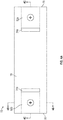
FIG. 4A is a plan view of a base of the module assembly according to an embodiment; -
FIG. 4B is a cross-sectional view of the base of a module assembly ofFIG. 4A taken along line Y-Y according to an embodiment; -
FIG. 4C is a cross-sectional view of the base of a module assembly ofFIG. 4A taken along line X-X according to an embodiment; -
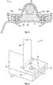
FIG. 5 is a cross-sectional view of the module assembly having an electrical harness coupled thereto according to an embodiment; -
FIG. 6 is a perspective end view of the module assembly according to an embodiment; and -
FIG. 7 is a plan view of a flexible connector of the module assembly according to an embodiment. - A detailed description of one or more embodiments of the disclosed apparatus and method are presented herein by way of exemplification and not limitation with reference to the Figures.
-
FIG. 1 schematically illustrates agas turbine engine 20. Thegas turbine engine 20 is disclosed herein as a two-spool turbofan that generally incorporates afan section 22, acompressor section 24, acombustor section 26 and aturbine section 28. Alternative engines might include other systems or features. Thefan section 22 drives air along a bypass flow path B in a bypass duct, while thecompressor section 24 drives air along a core flow path C for compression and communication into thecombustor section 26 then expansion through theturbine section 28. Although depicted as a two-spool turbofan gas turbine engine in the disclosed non-limiting embodiment, it should be understood that the concepts described herein are not limited to use with two-spool turbofans as the teachings may be applied to other types of turbine engines including three-spool architectures. - The
exemplary engine 20 generally includes alow speed spool 30 and ahigh speed spool 32 mounted for rotation about an engine central longitudinal axis A relative to an enginestatic structure 36 viaseveral bearing systems 38. It should be understood that various bearingsystems 38 at various locations may alternatively or additionally be provided, and the location of bearingsystems 38 may be varied as appropriate to the application. - The
low speed spool 30 generally includes aninner shaft 40 that interconnects afan 42, alow pressure compressor 44 and alow pressure turbine 46. Theinner shaft 40 is connected to thefan 42 through a speed change mechanism, which in exemplarygas turbine engine 20 is illustrated as a gearedarchitecture 48 to drive thefan 42 at a lower speed than thelow speed spool 30. Thehigh speed spool 32 includes anouter shaft 50 that interconnects ahigh pressure compressor 52 andhigh pressure turbine 54. Acombustor 56 is arranged inexemplary gas turbine 20 between thehigh pressure compressor 52 and thehigh pressure turbine 54. An enginestatic structure 36 is arranged generally between thehigh pressure turbine 54 and thelow pressure turbine 46. The enginestatic structure 36 furthersupports bearing systems 38 in theturbine section 28. Theinner shaft 40 and theouter shaft 50 are concentric and rotate via bearingsystems 38 about the engine central longitudinal axis A which is collinear with their longitudinal axes. - The core airflow is compressed by the
low pressure compressor 44 then thehigh pressure compressor 52, mixed and burned with fuel in thecombustor 56, then expanded over thehigh pressure turbine 54 andlow pressure turbine 46. Theturbines low speed spool 30 andhigh speed spool 32 in response to the expansion. It will be appreciated that each of the positions of thefan section 22,compressor section 24,combustor section 26,turbine section 28, and fandrive gear system 48 may be varied. For example,gear system 48 may be located aft ofcombustor section 26 or even aft ofturbine section 28, andfan section 22 may be positioned forward or aft of the location ofgear system 48. - The
engine 20 in one example is a high-bypass geared aircraft engine. In a further example, theengine 20 bypass ratio is greater than about six (6), with an example embodiment being greater than about ten (10), the gearedarchitecture 48 is an epicyclic gear train, such as a planetary gear system or other gear system, with a gear reduction ratio of greater than about 2.3 and thelow pressure turbine 46 has a pressure ratio that is greater than about five. In one disclosed embodiment, theengine 20 bypass ratio is greater than about ten (10:1), the fan diameter is significantly larger than that of thelow pressure compressor 44, and thelow pressure turbine 46 has a pressure ratio that is greater than about five 5:1.Low pressure turbine 46 pressure ratio is pressure measured prior to inlet oflow pressure turbine 46 as related to the pressure at the outlet of thelow pressure turbine 46 prior to an exhaust nozzle. The gearedarchitecture 48 may be an epicycle gear train, such as a planetary gear system or other gear system, with a gear reduction ratio of greater than about 2.3:1. It should be understood, however, that the above parameters are only exemplary of one embodiment of a geared architecture engine and that the present disclosure is applicable to other gas turbine engines including direct drive turbofans. - A significant amount of thrust is provided by the bypass flow B due to the high bypass ratio. The
fan section 22 of theengine 20 is designed for a particular flight condition--typically cruise at about 0.8Mach and about 35,000 feet (10,688 meters). The flight condition of 0.8 Mach and 35,000 ft (10,688 meters), with the engine at its best fuel consumption--also known as "bucket cruise Thrust Specific Fuel Consumption ('TSFC')"--is the industry standard parameter of lbm of fuel being burned divided by lbf of thrust the engine produces at that minimum point. "Low fan pressure ratio" is the pressure ratio across the fan blade alone, without a Fan Exit Guide Vane ("FEGV") system. The low fan pressure ratio as disclosed herein according to one non-limiting embodiment is less than about 1.45. "Low corrected fan tip speed" is the actual fan tip speed in ft/sec divided by an industry standard temperature correction of [(Tram °R)/(518.7 °R)]0.5. The "Low corrected fan tip speed" as disclosed herein according to one non-limiting embodiment is less than about 1150 ft/second (350.5 m/sec). - With reference now to
FIG. 2 , one or moreelectrical harnesses 60 are typically laid about the periphery of an exterior of a casing or housing of theengine 20. Theseelectrical harnesses 60 are configured to supply power to the various portions of theengine 20 or to electrical components or subsystems associated therewith. These harnesses 60 are typically held in place by one ormore mounting assemblies 70 disposed at various locations along the length of theelectrical harness 60 andengine 20. - Referring now to
FIGS. 3-7 , an example of a mountingassembly 70 for supporting anelectrical harness 60 at a desired location is illustrated. As shown, the mountingassembly 70 includes abase 72 and one or moreflexible connectors 86, such as straps for example, configured to cooperate with the base 72 to restrict movement of anelectrical harness 60 relative to the mountingassembly 70. The material used to form thebase 72 may be selected based on the environment of theengine 20 and one or more requirements associated with the specific area within which the mountingassembly 70 is located. The base 72 may be formed from any suitable material including, but not limited to Teflon, PEEK, and metal for example. In embodiments where thebase 72 is formed from a plastic material, thebase 72 may be injection molded. - In the illustrated, non-limiting embodiment, the
base 72 of the mountingassembly 70 is generally rectangular in shape and has a generally rectangular cross-section taken along either a first axis X, or a second axis Y, oriented substantially perpendicular to the first axis X and generally parallel to an axis defined by theelectrical harness 60. However, it should be understood that a base 72 having another shape is also considered within the scope of the disclosure. - One or
more channels 74 may be formed in thebase 72. In the illustrated non-limiting embodiment, afirst channel 74a is located adjacent a first side of thebase 72 and asecond channel 74b is located adjacent a second, opposite side of thebase 72. As shown, each of the first andsecond channels upper surface 76 of the base 72 to either the first orsecond side surface base 72, respectively. Although thefirst channel 74a and thesecond channel 74b are illustrated as being aligned, in other embodiments, thefirst channel 74a and thesecond channel 74b may be axially offset from one another about at least one of the first and second axis X, Y. In addition, it should be understood that the one ormore channels 74 illustrated and described herein are intended as an example only, and that a base of a mountingassembly 70 having any suitable number ofchannels 74 having any size, shape, and location are within the scope of the disclosure. - In an embodiment, the
base 72 includes aportion 82 located vertically upward of the one ormore channels 74. Thisportion 82 may be referred to herein as a cover and cooperates with the remainder of the base 72 to define at least a portion of thechannel 74. As shown, theupper surface 84 of thecover 82 may be generally flush with theupper surface 76 of the remainder of thebase 72. In embodiments of the mountingassembly 70 including both afirst channel 74a and asecond channel 74b, thebase 72 may include afirst cover 82a disposed upwardly adjacent thefirst channel 74a and asecond cover 82b disposed upwardly adjacent thesecond channel 74b. As best shown inFIGS. 4A-4C , the one ormore covers base 72, or in some embodiments removable from the remainder of thebase 72, to provide access to acorresponding channel more covers base 72, as shown inFIG. 6 . In yet another embodiment, the base 72 need not include acover 82 arranged vertically above thechannel 74. In such embodiments, an upper surface of thechannel 74 is not defined. - As previously suggested, the mounting
assembly 70 additionally includes one or more flexible connectors orstraps 86 configured to wrap at least partially about the circumference of theelectrical harness 60 to secure theelectrical harness 60 to thebase 72. An example of aflexible connector 86 is illustrated in more detail inFIG. 7 . Theflexible connector 86 shown includes afirst end 88 receivable within a corresponding channel formed in thebase 72. A mountinghole 89 may be formed in theflexible connector 86 near thefirst end 88 such that when thefirst end 88 is installed within a correspondingchannel 74 of thebase 72, afastener 90 may extend through thebase 72 and the mountinghole 89 to couple theflexible connector 86 to thebase 72. In an embodiment, aprotrusion 92 may extend fromsecond end 94 of theflexible connector 86 at an angle, such as perpendicular for example, to the body of theflexible connector 86. Theflexible connector 86 may be formed from any suitable non-rigid material. In an embodiment, theflexible connector 86 may be formed from PEEK, TEFZEL, Teflon, Metal, or any other suitable material that meets the engine requirements at a given location. In an embodiment, theflexible connector 86 may be formed form an encapsulated material. - With respect to the embodiment of the
module assembly 70 illustrated inFIG. 3 andFIG. 5 , theassembly 70 includes a firstflexible connector 86a associated with thefirst channel 74a and a secondflexible connector 86b associated with thesecond channel 74b. As shown, thefirst end 88a of the firstflexible connector 86a is arranged within thefirst channel 74a and secured to thebase 72 by afirst fastener 90 and afirst end 88b of the secondflexible connector 86b is arranged within thesecond channel 74b and secured to thebase 72 by asecond fastener 90. Although a fastener, such as a screw or bolt is shown, it should be understood that any suitable connector or fastening mechanism may be used to retain the first ends 88a, 88b of theflexible connector base 72. - The free
second end flexible connector 86a and the secondflexible connector 86b are positionable about an exterior surface of theelectrical harness 60. The firstflexible connector 86a and the secondflexible connector 86b extend at an angle to the axis of theharness 60. In an embodiment, thestraps flexible connectors electrical harness 60. In such embodiments, thestraps FIG. 5 , such as via Velcro, a hook and loop fastening system, or any other suitable connection mechanism. Inclusion of theprotrusion second end 94 of eachflexible connector flexible connector harness 60 to the module assembly70. - Alternatively, the
second end flexible connector base 72, such that thefirst end flexible connector electrical harness 60 and asecond end flexible connector electrical harness 60. In such embodiments, any suitable connection mechanism (not shown) may used to secure the free second end of eachflexible connector 86 to thebase 72. - In another embodiment, the mounting
assembly 70 includes a singleflexible connector 86. In such embodiments, theflexible connector 86, may, but need not include one or more mountingholes 89 and aprotrusion 92 located at eitherend assembly 70 including a singleflexible connector 86, a portion of theflexible connector 86 may wrap about alower surface 96 of thebase 72. In instances where thelower surface 96 of thebase 72 is mounted to anothercomponent 98, such as shown inFIG. 5 for example, thesingle strap 86 may be received within a channel or groove (not shown) formed in thelower surface 96 so as not to interfere with the connection between the base 72 and the anothercomponent 98. Thefirst end 88 of thestrap 86 may extend through thefirst channel 74a and thesecond end 92 of thestrap 86 may extend through thesecond channel 74b to wrap about theelectrical harness 60. As previously described, the first andsecond end flexible connector 86 may couple to one another, or to a portion of thebase 72. - In yet another embodiment, a
first end 88 of the singleflexible connector 86 may be affixed to a portion of thebase 72, such as within thefirst channel 74a for example. A free,second end 94 of theflexible connector 86 is configured to wrap about theelectrical harness 60 before being affixed or coupled to thebase 72, such as within thesecond channel 74b for example. In an embodiment, a position of one or both of thefirst end 88 and thesecond end 94 of theflexible connector 86 is movable relative to the base 72 to control the pressure applied by theflexible connector 86 to theelectrical harness 60. Regardless of the configuration of the one or moreflexible connectors 86 of the mountingassembly 70, the connection between the at least oneflexible connector 86 and thebase 72 and/or the connection between thestraps 86 may be adjustable such that the mountingassembly 70 is suitable for use with a variety of electrical harnesses of different sizes. - The mounting
assembly 70 as illustrated and described herein is suitable for use anelectrical harness 60 having various configurations of size and shape. Further, because thestrap 86 is formed from a fabric or plastic material, rather than a metal, potential chafing between theharness 60 and the mountingassembly 70 is eliminated. Further, in embodiments where sever mountingassemblies 70 are used to secure an electrical harness at various locations about an engine, the plurality of mountingassemblies 70 may be substantially identical, or may be different. For example, one or more components of the mountingassembly 70 may be formed from different materials depending on the position of the mountingassembly 70 relative to theengine 20. - The term "about" is intended to include the degree of error associated with measurement of the particular quantity based upon the equipment available at the time of filing the application.
- The terminology used herein is for the purpose of describing particular embodiments only and is not intended to be limiting of the present disclosure. As used herein, the singular forms "a", "an" and "the" are intended to include the plural forms as well, unless the context clearly indicates otherwise. It will be further understood that the terms "comprises" and/or "comprising," when used in this specification, specify the presence of stated features, integers, steps, operations, elements, and/or components, but do not preclude the presence or addition of one or more other features, integers, steps, operations, element components, and/or groups thereof.
- While the present disclosure has been described with reference to an exemplary embodiment or embodiments, it will be understood by those skilled in the art that various changes may be made and equivalents may be substituted for elements thereof without departing from the scope of the present invention defined by the appended claims. In addition, many modifications may be made to adapt a particular situation or material to the teachings of the present disclosure without departing from the scope of the invention. Therefore, it is intended that the present disclosure not be limited to the particular embodiment disclosed as the best mode contemplated for carrying out this present disclosure, but that the present disclosure will include all embodiments falling within the scope of the claims.
Claims (15)
- A mounting assembly for restricting movement of an electrical harness of a gas turbine engine, comprising:a base;a first channel formed in the base and extending between a first surface and a second surface of the base;a second channel formed in the base and extending between the first surface and a third surface of the base, the second surface and the third surface being distinct; andat least one flexible connector receivable within the first channel and the second channel, wherein at least a portion of the at least one flexible connector extends about the electrical harness to couple the electrical harness to the base.
- The mounting assembly of claim 1, wherein the first channel is located adjacent a first side of the base and the second channel is positioned adjacent a second side of the base.
- The mounting assembly of claim 1 or 2, wherein the first channel extends from an upper surface of the base to a first side surface of the base and the second channel extends from the upper surface of the base to a second side surface of the base; preferably
wherein the first side surface is disposed opposite the second side surface. - The mounting assembly of claim 1, 2 or 3, wherein the at least one flexible connector includes a first end and a second end, at least one of the first end and the second end being affixed within one of the first channel and the second channel.
- The mounting assembly of claim 4, wherein the at least one flexible connector includes a single flexible connector, the first end of the single flexible connector being affixed within the first channel and the second end of the single flexible connector being affixed within the second channel.
- The mounting assembly of claim 4, wherein the at least one flexible connector includes a first flexible connector and a second flexible connector, a first end of the first flexible connector being affixed within the first channel and a first end of the second flexible connector being affixed within the second channel; preferably
wherein a second end of the first flexible connector is coupleable to a second end of the second flexible connector to couple the electrical harness to the base; and more preferably
wherein the second end of the first connector is coupleable to the second end of the second flexible connector via a hook and loop-type attachment. - The mounting assembly of claim 6, wherein a tab is formed at a second end of at least one of the first flexible connector and the second flexible connector.
- The mounting assembly of claim 1, 2 or 3, wherein the at least one flexible connector includes a single flexible connector having a first end and a second end, the first end being extendable through the first channel and the second end being extendable through the second channel; preferably
wherein the first end is connectable to the second end to couple the electrical harness to the base; and more preferably
wherein the first end is coupleable to the second end via a hook and loop-type attachment. - The mounting assembly of any preceding claim, wherein a force applied by the at least one connector to the electrical harness is adjustable.
- A gas turbine engine comprising:a mounting surface;an electrical harness; andthe mounting assembly of any preceding claim, wherein the base is connected to the mounting surface.
- The gas turbine engine of claim 10, wherein the engine further comprises a casing and the mounting surface is an exterior surface of the casing.
- The gas turbine engine of claim 10 or 11, wherein the engine is an aircraft engine.
- A method of restricting movement of an electrical harness relative to a gas turbine engine comprising:positioning the electrical harness in contact with a base of a mounting assembly;wrapping at least one flexible connector about the electrical harness, the at least one flexible connector extending through a first channel and a second channel formed in the base, the first channel being formed between a first surface and a second surface of the base and the second channel being formed between a first surface and a third surface of the base, the second surface and the third surface being distinct; andrestricting movement of the at least one flexible connector relative to the base.
- The method of claim 13, wherein the at least one flexible connector includes affixing a first end of the at least one flexible connector to a second end of the at least one flexible connector.
- The method of claim 13, wherein restricting movement of the at least one flexible connector relative to the base includes affixing an end of the at least one flexible connector to the base.
Applications Claiming Priority (1)
| Application Number | Priority Date | Filing Date | Title |
|---|---|---|---|
| US16/036,628 US10690267B2 (en) | 2018-07-16 | 2018-07-16 | Adjustable holding assembly |
Publications (2)
| Publication Number | Publication Date |
|---|---|
| EP3597487A1 true EP3597487A1 (en) | 2020-01-22 |
| EP3597487B1 EP3597487B1 (en) | 2022-05-25 |
Family
ID=67297051
Family Applications (1)
| Application Number | Title | Priority Date | Filing Date |
|---|---|---|---|
| EP19186294.5A Active EP3597487B1 (en) | 2018-07-16 | 2019-07-15 | Adjustable holding assembly |
Country Status (2)
| Country | Link |
|---|---|
| US (1) | US10690267B2 (en) |
| EP (1) | EP3597487B1 (en) |
Families Citing this family (6)
| Publication number | Priority date | Publication date | Assignee | Title |
|---|---|---|---|---|
| US10690267B2 (en) * | 2018-07-16 | 2020-06-23 | Raytheon Technologies Corporation | Adjustable holding assembly |
| US11427346B2 (en) * | 2018-09-28 | 2022-08-30 | Gulfstream Aerospace Corporation | Cable retainer apparatus and method for retaining a cable |
| US10907750B2 (en) * | 2019-04-29 | 2021-02-02 | Aptiv Technologies Limited | Modular retainer assembly |
| FR3122694B1 (en) * | 2021-05-07 | 2024-03-29 | Safran Aircraft Engines | Turbojet equipped with a fixing assembly arranged on a fan casing |
| US12300407B2 (en) * | 2022-12-22 | 2025-05-13 | The Boeing Company | Connector to attach wiring to a housing |
| US20250129871A1 (en) * | 2023-10-24 | 2025-04-24 | Rtx Corporation | Damped fluid line for aircraft engine |
Citations (8)
| Publication number | Priority date | Publication date | Assignee | Title |
|---|---|---|---|---|
| US3632071A (en) * | 1969-11-24 | 1972-01-04 | Panduit Tinley Park | Mount for receiving and retaining a strap |
| GB1525801A (en) * | 1975-01-08 | 1978-09-20 | Panduit Corp | Mounts for holding elongate objects |
| US4379537A (en) * | 1981-08-10 | 1983-04-12 | Whipple Patent Management Corporation | Cable hanger |
| DE10010933C1 (en) * | 2000-03-06 | 2001-08-16 | Daimler Chrysler Ag | Cable holder for fastening cables in vehicle structures has a fastening clip with a hole for fastening it with connector elements to a vehicle structure and a dish-shaped bulge to put the cable on forming one piece with the fastening clip. |
| US20020117321A1 (en) * | 2001-02-26 | 2002-08-29 | Beebe Joyce E. | Rigidized protective sleeving |
| US20140050571A1 (en) * | 2012-08-16 | 2014-02-20 | Marc R. Sauerhoefer | Harness support and mount |
| WO2014193351A1 (en) * | 2013-05-29 | 2014-12-04 | International Engine Intellectual Property Company, Llc | Harness clip and system for clipping wiring harness |
| EP2908039A1 (en) * | 2014-02-12 | 2015-08-19 | HEBOTEC GmbH | Fastening system |
Family Cites Families (16)
| Publication number | Priority date | Publication date | Assignee | Title |
|---|---|---|---|---|
| US2409772A (en) | 1944-05-13 | 1946-10-22 | Adel Prec Products Corp | Adjustable harness clip |
| US4338707A (en) * | 1980-03-10 | 1982-07-13 | Ta Mfg. Corp. | Clamp |
| US4854015A (en) | 1988-06-10 | 1989-08-08 | The Boeing Company | Adjustable loop clamp |
| US5390883A (en) | 1994-04-11 | 1995-02-21 | Songhurst; Ronald W. | Releasable mounting binder for wires and cables |
| US5673889A (en) * | 1995-09-28 | 1997-10-07 | Devalcourt; Ricky D. | Wind surfing equipment holder |
| US6683258B1 (en) | 2003-04-03 | 2004-01-27 | 3M Innovative Properties Company | Cable restraining device |
| US7497718B2 (en) | 2006-11-08 | 2009-03-03 | International Truck Intellectual Property Company, Llc | Routing clip elements with a living hinge and interlocking closure |
| US8235345B2 (en) * | 2008-04-30 | 2012-08-07 | United Technologies Corp. | Gas turbine engine systems and related methods involving thermally isolated retention |
| GB201001002D0 (en) | 2010-01-22 | 2010-03-10 | Airbus Operations Ltd | A bracket for attaching an electrical cable to a vehicle |
| FR2965670B1 (en) | 2010-09-30 | 2012-10-12 | Airbus Operations Sas | DEVICE FOR FASTENING CABLES |
| FR2980549B1 (en) | 2011-09-22 | 2014-11-28 | Aplix Sa | ATTACHING NECK FOR LONG ELEMENTS |
| GB2497807B (en) * | 2011-12-22 | 2014-09-10 | Rolls Royce Plc | Electrical harness |
| FR2986829B1 (en) * | 2012-02-09 | 2014-03-21 | Safran | TURBOMACHINE SUPPORT PIECE WITH HYBRID STRUCTURE |
| GB201301431D0 (en) * | 2013-01-28 | 2013-03-13 | Rolls Royce Plc | Component having a heat protection system |
| GB201409189D0 (en) * | 2014-05-23 | 2014-07-09 | Rolls Royce Plc | Fire resistant electrical panel |
| US10690267B2 (en) * | 2018-07-16 | 2020-06-23 | Raytheon Technologies Corporation | Adjustable holding assembly |
-
2018
- 2018-07-16 US US16/036,628 patent/US10690267B2/en active Active
-
2019
- 2019-07-15 EP EP19186294.5A patent/EP3597487B1/en active Active
Patent Citations (8)
| Publication number | Priority date | Publication date | Assignee | Title |
|---|---|---|---|---|
| US3632071A (en) * | 1969-11-24 | 1972-01-04 | Panduit Tinley Park | Mount for receiving and retaining a strap |
| GB1525801A (en) * | 1975-01-08 | 1978-09-20 | Panduit Corp | Mounts for holding elongate objects |
| US4379537A (en) * | 1981-08-10 | 1983-04-12 | Whipple Patent Management Corporation | Cable hanger |
| DE10010933C1 (en) * | 2000-03-06 | 2001-08-16 | Daimler Chrysler Ag | Cable holder for fastening cables in vehicle structures has a fastening clip with a hole for fastening it with connector elements to a vehicle structure and a dish-shaped bulge to put the cable on forming one piece with the fastening clip. |
| US20020117321A1 (en) * | 2001-02-26 | 2002-08-29 | Beebe Joyce E. | Rigidized protective sleeving |
| US20140050571A1 (en) * | 2012-08-16 | 2014-02-20 | Marc R. Sauerhoefer | Harness support and mount |
| WO2014193351A1 (en) * | 2013-05-29 | 2014-12-04 | International Engine Intellectual Property Company, Llc | Harness clip and system for clipping wiring harness |
| EP2908039A1 (en) * | 2014-02-12 | 2015-08-19 | HEBOTEC GmbH | Fastening system |
Also Published As
| Publication number | Publication date |
|---|---|
| US20200018427A1 (en) | 2020-01-16 |
| US10690267B2 (en) | 2020-06-23 |
| EP3597487B1 (en) | 2022-05-25 |
Similar Documents
| Publication | Publication Date | Title |
|---|---|---|
| EP3597487B1 (en) | Adjustable holding assembly | |
| EP3789603A1 (en) | Electric power assist for in-flight engine re-start | |
| EP3054128B1 (en) | Gearbox for gas turbine engine | |
| EP3879074A1 (en) | Tail cone assembly for a gas turbine engine and mounted generator | |
| EP3454033B1 (en) | Near full hoop electrical axial shift wear indication sensor | |
| EP3569839B1 (en) | Anti-rotation device for fasteners | |
| EP4112909A1 (en) | Hybrid electric variable area turbine | |
| US9731388B2 (en) | Method and fixture for airfoil array assembly | |
| EP4421299A2 (en) | Hybrid electric engine and nacelle system | |
| EP3382279A1 (en) | Washer for combustor assembly | |
| EP2930303A1 (en) | Gas turbine engine coupling stack | |
| EP3584406A1 (en) | Clip and pin balance for rotor | |
| US11286797B2 (en) | Gas turbine engine stator vane base shape | |
| EP3431716A1 (en) | Variable-pitch vane assembly and corresponding assembly method | |
| EP3290660B1 (en) | Thermal barrier washer for a composite boss | |
| US11852038B2 (en) | Stator retention of gas turbine engine | |
| EP3611358B1 (en) | Bleed valve actuation system | |
| US9835091B2 (en) | Multiple piece shroud feedthru enclosure | |
| US10808559B2 (en) | Guide vane retention assembly for gas turbine engine | |
| US9297307B2 (en) | Power cable and connector arrangement for a gas turbine engine | |
| EP4715182A1 (en) | Wire harness block clamp | |
| EP3428404B1 (en) | Stator vane assembly for a gas turbine engine | |
| US12253009B1 (en) | Instrumented stator with extended internal passages | |
| US20250092798A1 (en) | Anti-rotation feature for instrumentation of gas turbine engine | |
| US20220065116A1 (en) | Wound retaining wire |
Legal Events
| Date | Code | Title | Description |
|---|---|---|---|
| PUAI | Public reference made under article 153(3) epc to a published international application that has entered the european phase |
Free format text: ORIGINAL CODE: 0009012 |
|
| STAA | Information on the status of an ep patent application or granted ep patent |
Free format text: STATUS: THE APPLICATION HAS BEEN PUBLISHED |
|
| AK | Designated contracting states |
Kind code of ref document: A1 Designated state(s): AL AT BE BG CH CY CZ DE DK EE ES FI FR GB GR HR HU IE IS IT LI LT LU LV MC MK MT NL NO PL PT RO RS SE SI SK SM TR |
|
| AX | Request for extension of the european patent |
Extension state: BA ME |
|
| STAA | Information on the status of an ep patent application or granted ep patent |
Free format text: STATUS: REQUEST FOR EXAMINATION WAS MADE |
|
| 17P | Request for examination filed |
Effective date: 20200722 |
|
| RBV | Designated contracting states (corrected) |
Designated state(s): AL AT BE BG CH CY CZ DE DK EE ES FI FR GB GR HR HU IE IS IT LI LT LU LV MC MK MT NL NO PL PT RO RS SE SI SK SM TR |
|
| RAP1 | Party data changed (applicant data changed or rights of an application transferred) |
Owner name: RAYTHEON TECHNOLOGIES CORPORATION |
|
| GRAP | Despatch of communication of intention to grant a patent |
Free format text: ORIGINAL CODE: EPIDOSNIGR1 |
|
| STAA | Information on the status of an ep patent application or granted ep patent |
Free format text: STATUS: GRANT OF PATENT IS INTENDED |
|
| INTG | Intention to grant announced |
Effective date: 20211206 |
|
| GRAS | Grant fee paid |
Free format text: ORIGINAL CODE: EPIDOSNIGR3 |
|
| GRAA | (expected) grant |
Free format text: ORIGINAL CODE: 0009210 |
|
| STAA | Information on the status of an ep patent application or granted ep patent |
Free format text: STATUS: THE PATENT HAS BEEN GRANTED |
|
| AK | Designated contracting states |
Kind code of ref document: B1 Designated state(s): AL AT BE BG CH CY CZ DE DK EE ES FI FR GB GR HR HU IE IS IT LI LT LU LV MC MK MT NL NO PL PT RO RS SE SI SK SM TR |
|
| REG | Reference to a national code |
Ref country code: GB Ref legal event code: FG4D |
|
| REG | Reference to a national code |
Ref country code: CH Ref legal event code: EP |
|
| REG | Reference to a national code |
Ref country code: AT Ref legal event code: REF Ref document number: 1494146 Country of ref document: AT Kind code of ref document: T Effective date: 20220615 Ref country code: DE Ref legal event code: R096 Ref document number: 602019015192 Country of ref document: DE |
|
| REG | Reference to a national code |
Ref country code: IE Ref legal event code: FG4D |
|
| REG | Reference to a national code |
Ref country code: LT Ref legal event code: MG9D |
|
| REG | Reference to a national code |
Ref country code: NL Ref legal event code: MP Effective date: 20220525 |
|
| REG | Reference to a national code |
Ref country code: AT Ref legal event code: MK05 Ref document number: 1494146 Country of ref document: AT Kind code of ref document: T Effective date: 20220525 |
|
| PG25 | Lapsed in a contracting state [announced via postgrant information from national office to epo] |
Ref country code: SE Free format text: LAPSE BECAUSE OF FAILURE TO SUBMIT A TRANSLATION OF THE DESCRIPTION OR TO PAY THE FEE WITHIN THE PRESCRIBED TIME-LIMIT Effective date: 20220525 Ref country code: PT Free format text: LAPSE BECAUSE OF FAILURE TO SUBMIT A TRANSLATION OF THE DESCRIPTION OR TO PAY THE FEE WITHIN THE PRESCRIBED TIME-LIMIT Effective date: 20220926 Ref country code: NO Free format text: LAPSE BECAUSE OF FAILURE TO SUBMIT A TRANSLATION OF THE DESCRIPTION OR TO PAY THE FEE WITHIN THE PRESCRIBED TIME-LIMIT Effective date: 20220825 Ref country code: NL Free format text: LAPSE BECAUSE OF FAILURE TO SUBMIT A TRANSLATION OF THE DESCRIPTION OR TO PAY THE FEE WITHIN THE PRESCRIBED TIME-LIMIT Effective date: 20220525 Ref country code: LT Free format text: LAPSE BECAUSE OF FAILURE TO SUBMIT A TRANSLATION OF THE DESCRIPTION OR TO PAY THE FEE WITHIN THE PRESCRIBED TIME-LIMIT Effective date: 20220525 Ref country code: HR Free format text: LAPSE BECAUSE OF FAILURE TO SUBMIT A TRANSLATION OF THE DESCRIPTION OR TO PAY THE FEE WITHIN THE PRESCRIBED TIME-LIMIT Effective date: 20220525 Ref country code: GR Free format text: LAPSE BECAUSE OF FAILURE TO SUBMIT A TRANSLATION OF THE DESCRIPTION OR TO PAY THE FEE WITHIN THE PRESCRIBED TIME-LIMIT Effective date: 20220826 Ref country code: FI Free format text: LAPSE BECAUSE OF FAILURE TO SUBMIT A TRANSLATION OF THE DESCRIPTION OR TO PAY THE FEE WITHIN THE PRESCRIBED TIME-LIMIT Effective date: 20220525 Ref country code: ES Free format text: LAPSE BECAUSE OF FAILURE TO SUBMIT A TRANSLATION OF THE DESCRIPTION OR TO PAY THE FEE WITHIN THE PRESCRIBED TIME-LIMIT Effective date: 20220525 Ref country code: BG Free format text: LAPSE BECAUSE OF FAILURE TO SUBMIT A TRANSLATION OF THE DESCRIPTION OR TO PAY THE FEE WITHIN THE PRESCRIBED TIME-LIMIT Effective date: 20220825 Ref country code: AT Free format text: LAPSE BECAUSE OF FAILURE TO SUBMIT A TRANSLATION OF THE DESCRIPTION OR TO PAY THE FEE WITHIN THE PRESCRIBED TIME-LIMIT Effective date: 20220525 |
|
| PG25 | Lapsed in a contracting state [announced via postgrant information from national office to epo] |
Ref country code: RS Free format text: LAPSE BECAUSE OF FAILURE TO SUBMIT A TRANSLATION OF THE DESCRIPTION OR TO PAY THE FEE WITHIN THE PRESCRIBED TIME-LIMIT Effective date: 20220525 Ref country code: PL Free format text: LAPSE BECAUSE OF FAILURE TO SUBMIT A TRANSLATION OF THE DESCRIPTION OR TO PAY THE FEE WITHIN THE PRESCRIBED TIME-LIMIT Effective date: 20220525 Ref country code: LV Free format text: LAPSE BECAUSE OF FAILURE TO SUBMIT A TRANSLATION OF THE DESCRIPTION OR TO PAY THE FEE WITHIN THE PRESCRIBED TIME-LIMIT Effective date: 20220525 Ref country code: IS Free format text: LAPSE BECAUSE OF FAILURE TO SUBMIT A TRANSLATION OF THE DESCRIPTION OR TO PAY THE FEE WITHIN THE PRESCRIBED TIME-LIMIT Effective date: 20220925 |
|
| PG25 | Lapsed in a contracting state [announced via postgrant information from national office to epo] |
Ref country code: SM Free format text: LAPSE BECAUSE OF FAILURE TO SUBMIT A TRANSLATION OF THE DESCRIPTION OR TO PAY THE FEE WITHIN THE PRESCRIBED TIME-LIMIT Effective date: 20220525 Ref country code: SK Free format text: LAPSE BECAUSE OF FAILURE TO SUBMIT A TRANSLATION OF THE DESCRIPTION OR TO PAY THE FEE WITHIN THE PRESCRIBED TIME-LIMIT Effective date: 20220525 Ref country code: RO Free format text: LAPSE BECAUSE OF FAILURE TO SUBMIT A TRANSLATION OF THE DESCRIPTION OR TO PAY THE FEE WITHIN THE PRESCRIBED TIME-LIMIT Effective date: 20220525 Ref country code: EE Free format text: LAPSE BECAUSE OF FAILURE TO SUBMIT A TRANSLATION OF THE DESCRIPTION OR TO PAY THE FEE WITHIN THE PRESCRIBED TIME-LIMIT Effective date: 20220525 Ref country code: DK Free format text: LAPSE BECAUSE OF FAILURE TO SUBMIT A TRANSLATION OF THE DESCRIPTION OR TO PAY THE FEE WITHIN THE PRESCRIBED TIME-LIMIT Effective date: 20220525 Ref country code: CZ Free format text: LAPSE BECAUSE OF FAILURE TO SUBMIT A TRANSLATION OF THE DESCRIPTION OR TO PAY THE FEE WITHIN THE PRESCRIBED TIME-LIMIT Effective date: 20220525 |
|
| PG25 | Lapsed in a contracting state [announced via postgrant information from national office to epo] |
Ref country code: MC Free format text: LAPSE BECAUSE OF FAILURE TO SUBMIT A TRANSLATION OF THE DESCRIPTION OR TO PAY THE FEE WITHIN THE PRESCRIBED TIME-LIMIT Effective date: 20220525 |
|
| REG | Reference to a national code |
Ref country code: DE Ref legal event code: R097 Ref document number: 602019015192 Country of ref document: DE Ref country code: CH Ref legal event code: PL |
|
| REG | Reference to a national code |
Ref country code: BE Ref legal event code: MM Effective date: 20220731 |
|
| PG25 | Lapsed in a contracting state [announced via postgrant information from national office to epo] |
Ref country code: AL Free format text: LAPSE BECAUSE OF FAILURE TO SUBMIT A TRANSLATION OF THE DESCRIPTION OR TO PAY THE FEE WITHIN THE PRESCRIBED TIME-LIMIT Effective date: 20220525 |
|
| PLBE | No opposition filed within time limit |
Free format text: ORIGINAL CODE: 0009261 |
|
| STAA | Information on the status of an ep patent application or granted ep patent |
Free format text: STATUS: NO OPPOSITION FILED WITHIN TIME LIMIT |
|
| PG25 | Lapsed in a contracting state [announced via postgrant information from national office to epo] |
Ref country code: LU Free format text: LAPSE BECAUSE OF NON-PAYMENT OF DUE FEES Effective date: 20220715 Ref country code: LI Free format text: LAPSE BECAUSE OF NON-PAYMENT OF DUE FEES Effective date: 20220731 Ref country code: CH Free format text: LAPSE BECAUSE OF NON-PAYMENT OF DUE FEES Effective date: 20220731 |
|
| 26N | No opposition filed |
Effective date: 20230228 |
|
| PG25 | Lapsed in a contracting state [announced via postgrant information from national office to epo] |
Ref country code: SI Free format text: LAPSE BECAUSE OF FAILURE TO SUBMIT A TRANSLATION OF THE DESCRIPTION OR TO PAY THE FEE WITHIN THE PRESCRIBED TIME-LIMIT Effective date: 20220525 Ref country code: BE Free format text: LAPSE BECAUSE OF NON-PAYMENT OF DUE FEES Effective date: 20220731 |
|
| P01 | Opt-out of the competence of the unified patent court (upc) registered |
Effective date: 20230521 |
|
| PG25 | Lapsed in a contracting state [announced via postgrant information from national office to epo] |
Ref country code: IE Free format text: LAPSE BECAUSE OF NON-PAYMENT OF DUE FEES Effective date: 20220715 |
|
| PG25 | Lapsed in a contracting state [announced via postgrant information from national office to epo] |
Ref country code: IT Free format text: LAPSE BECAUSE OF FAILURE TO SUBMIT A TRANSLATION OF THE DESCRIPTION OR TO PAY THE FEE WITHIN THE PRESCRIBED TIME-LIMIT Effective date: 20220525 |
|
| PG25 | Lapsed in a contracting state [announced via postgrant information from national office to epo] |
Ref country code: HU Free format text: LAPSE BECAUSE OF FAILURE TO SUBMIT A TRANSLATION OF THE DESCRIPTION OR TO PAY THE FEE WITHIN THE PRESCRIBED TIME-LIMIT; INVALID AB INITIO Effective date: 20190715 |
|
| PG25 | Lapsed in a contracting state [announced via postgrant information from national office to epo] |
Ref country code: MK Free format text: LAPSE BECAUSE OF FAILURE TO SUBMIT A TRANSLATION OF THE DESCRIPTION OR TO PAY THE FEE WITHIN THE PRESCRIBED TIME-LIMIT Effective date: 20220525 Ref country code: CY Free format text: LAPSE BECAUSE OF FAILURE TO SUBMIT A TRANSLATION OF THE DESCRIPTION OR TO PAY THE FEE WITHIN THE PRESCRIBED TIME-LIMIT Effective date: 20220525 |
|
| PG25 | Lapsed in a contracting state [announced via postgrant information from national office to epo] |
Ref country code: TR Free format text: LAPSE BECAUSE OF FAILURE TO SUBMIT A TRANSLATION OF THE DESCRIPTION OR TO PAY THE FEE WITHIN THE PRESCRIBED TIME-LIMIT Effective date: 20220525 |
|
| PG25 | Lapsed in a contracting state [announced via postgrant information from national office to epo] |
Ref country code: MT Free format text: LAPSE BECAUSE OF FAILURE TO SUBMIT A TRANSLATION OF THE DESCRIPTION OR TO PAY THE FEE WITHIN THE PRESCRIBED TIME-LIMIT Effective date: 20220525 |
|
| PG25 | Lapsed in a contracting state [announced via postgrant information from national office to epo] |
Ref country code: BG Free format text: LAPSE BECAUSE OF FAILURE TO SUBMIT A TRANSLATION OF THE DESCRIPTION OR TO PAY THE FEE WITHIN THE PRESCRIBED TIME-LIMIT Effective date: 20220525 |
|
| PG25 | Lapsed in a contracting state [announced via postgrant information from national office to epo] |
Ref country code: BG Free format text: LAPSE BECAUSE OF FAILURE TO SUBMIT A TRANSLATION OF THE DESCRIPTION OR TO PAY THE FEE WITHIN THE PRESCRIBED TIME-LIMIT Effective date: 20220525 |
|
| PGFP | Annual fee paid to national office [announced via postgrant information from national office to epo] |
Ref country code: GB Payment date: 20250619 Year of fee payment: 7 |
|
| PGFP | Annual fee paid to national office [announced via postgrant information from national office to epo] |
Ref country code: FR Payment date: 20250620 Year of fee payment: 7 |
|
| REG | Reference to a national code |
Ref country code: DE Ref legal event code: R081 Ref document number: 602019015192 Country of ref document: DE Owner name: RTX CORPORATION (N.D.GES.D. STAATES DELAWARE),, US Free format text: FORMER OWNER: RAYTHEON TECHNOLOGIES CORPORATION, FARMINGTON, CT, US |
|
| PGFP | Annual fee paid to national office [announced via postgrant information from national office to epo] |
Ref country code: DE Payment date: 20250620 Year of fee payment: 7 |