EP3597400A1 - Additive-manufacturing systems and methods - Google Patents
Additive-manufacturing systems and methods Download PDFInfo
- Publication number
- EP3597400A1 EP3597400A1 EP19181287.4A EP19181287A EP3597400A1 EP 3597400 A1 EP3597400 A1 EP 3597400A1 EP 19181287 A EP19181287 A EP 19181287A EP 3597400 A1 EP3597400 A1 EP 3597400A1
- Authority
- EP
- European Patent Office
- Prior art keywords
- additive manufacturing
- component
- head
- powder bed
- energy
- Prior art date
- Legal status (The legal status is an assumption and is not a legal conclusion. Google has not performed a legal analysis and makes no representation as to the accuracy of the status listed.)
- Granted
Links
Images



Classifications
-
- B—PERFORMING OPERATIONS; TRANSPORTING
- B29—WORKING OF PLASTICS; WORKING OF SUBSTANCES IN A PLASTIC STATE IN GENERAL
- B29C—SHAPING OR JOINING OF PLASTICS; SHAPING OF MATERIAL IN A PLASTIC STATE, NOT OTHERWISE PROVIDED FOR; AFTER-TREATMENT OF THE SHAPED PRODUCTS, e.g. REPAIRING
- B29C64/00—Additive manufacturing, i.e. manufacturing of three-dimensional [3D] objects by additive deposition, additive agglomeration or additive layering, e.g. by 3D printing, stereolithography or selective laser sintering
- B29C64/20—Apparatus for additive manufacturing; Details thereof or accessories therefor
-
- B—PERFORMING OPERATIONS; TRANSPORTING
- B22—CASTING; POWDER METALLURGY
- B22F—WORKING METALLIC POWDER; MANUFACTURE OF ARTICLES FROM METALLIC POWDER; MAKING METALLIC POWDER; APPARATUS OR DEVICES SPECIALLY ADAPTED FOR METALLIC POWDER
- B22F10/00—Additive manufacturing of workpieces or articles from metallic powder
-
- B—PERFORMING OPERATIONS; TRANSPORTING
- B22—CASTING; POWDER METALLURGY
- B22F—WORKING METALLIC POWDER; MANUFACTURE OF ARTICLES FROM METALLIC POWDER; MAKING METALLIC POWDER; APPARATUS OR DEVICES SPECIALLY ADAPTED FOR METALLIC POWDER
- B22F10/00—Additive manufacturing of workpieces or articles from metallic powder
- B22F10/20—Direct sintering or melting
- B22F10/28—Powder bed fusion, e.g. selective laser melting [SLM] or electron beam melting [EBM]
-
- B—PERFORMING OPERATIONS; TRANSPORTING
- B22—CASTING; POWDER METALLURGY
- B22F—WORKING METALLIC POWDER; MANUFACTURE OF ARTICLES FROM METALLIC POWDER; MAKING METALLIC POWDER; APPARATUS OR DEVICES SPECIALLY ADAPTED FOR METALLIC POWDER
- B22F10/00—Additive manufacturing of workpieces or articles from metallic powder
- B22F10/50—Treatment of workpieces or articles during build-up, e.g. treatments applied to fused layers during build-up
-
- B—PERFORMING OPERATIONS; TRANSPORTING
- B22—CASTING; POWDER METALLURGY
- B22F—WORKING METALLIC POWDER; MANUFACTURE OF ARTICLES FROM METALLIC POWDER; MAKING METALLIC POWDER; APPARATUS OR DEVICES SPECIALLY ADAPTED FOR METALLIC POWDER
- B22F10/00—Additive manufacturing of workpieces or articles from metallic powder
- B22F10/80—Data acquisition or data processing
-
- B—PERFORMING OPERATIONS; TRANSPORTING
- B22—CASTING; POWDER METALLURGY
- B22F—WORKING METALLIC POWDER; MANUFACTURE OF ARTICLES FROM METALLIC POWDER; MAKING METALLIC POWDER; APPARATUS OR DEVICES SPECIALLY ADAPTED FOR METALLIC POWDER
- B22F12/00—Apparatus or devices specially adapted for additive manufacturing; Auxiliary means for additive manufacturing; Combinations of additive manufacturing apparatus or devices with other processing apparatus or devices
- B22F12/22—Driving means
- B22F12/222—Driving means for motion along a direction orthogonal to the plane of a layer
-
- B—PERFORMING OPERATIONS; TRANSPORTING
- B22—CASTING; POWDER METALLURGY
- B22F—WORKING METALLIC POWDER; MANUFACTURE OF ARTICLES FROM METALLIC POWDER; MAKING METALLIC POWDER; APPARATUS OR DEVICES SPECIALLY ADAPTED FOR METALLIC POWDER
- B22F12/00—Apparatus or devices specially adapted for additive manufacturing; Auxiliary means for additive manufacturing; Combinations of additive manufacturing apparatus or devices with other processing apparatus or devices
- B22F12/40—Radiation means
- B22F12/44—Radiation means characterised by the configuration of the radiation means
- B22F12/45—Two or more
-
- B—PERFORMING OPERATIONS; TRANSPORTING
- B22—CASTING; POWDER METALLURGY
- B22F—WORKING METALLIC POWDER; MANUFACTURE OF ARTICLES FROM METALLIC POWDER; MAKING METALLIC POWDER; APPARATUS OR DEVICES SPECIALLY ADAPTED FOR METALLIC POWDER
- B22F3/00—Manufacture of workpieces or articles from metallic powder characterised by the manner of compacting or sintering; Apparatus specially adapted therefor ; Presses and furnaces
- B22F3/003—Apparatus, e.g. furnaces
-
- B—PERFORMING OPERATIONS; TRANSPORTING
- B22—CASTING; POWDER METALLURGY
- B22F—WORKING METALLIC POWDER; MANUFACTURE OF ARTICLES FROM METALLIC POWDER; MAKING METALLIC POWDER; APPARATUS OR DEVICES SPECIALLY ADAPTED FOR METALLIC POWDER
- B22F3/00—Manufacture of workpieces or articles from metallic powder characterised by the manner of compacting or sintering; Apparatus specially adapted therefor ; Presses and furnaces
- B22F3/24—After-treatment of workpieces or articles
-
- B—PERFORMING OPERATIONS; TRANSPORTING
- B29—WORKING OF PLASTICS; WORKING OF SUBSTANCES IN A PLASTIC STATE IN GENERAL
- B29C—SHAPING OR JOINING OF PLASTICS; SHAPING OF MATERIAL IN A PLASTIC STATE, NOT OTHERWISE PROVIDED FOR; AFTER-TREATMENT OF THE SHAPED PRODUCTS, e.g. REPAIRING
- B29C64/00—Additive manufacturing, i.e. manufacturing of three-dimensional [3D] objects by additive deposition, additive agglomeration or additive layering, e.g. by 3D printing, stereolithography or selective laser sintering
- B29C64/10—Processes of additive manufacturing
- B29C64/141—Processes of additive manufacturing using only solid materials
- B29C64/153—Processes of additive manufacturing using only solid materials using layers of powder being selectively joined, e.g. by selective laser sintering or melting
-
- B—PERFORMING OPERATIONS; TRANSPORTING
- B29—WORKING OF PLASTICS; WORKING OF SUBSTANCES IN A PLASTIC STATE IN GENERAL
- B29C—SHAPING OR JOINING OF PLASTICS; SHAPING OF MATERIAL IN A PLASTIC STATE, NOT OTHERWISE PROVIDED FOR; AFTER-TREATMENT OF THE SHAPED PRODUCTS, e.g. REPAIRING
- B29C64/00—Additive manufacturing, i.e. manufacturing of three-dimensional [3D] objects by additive deposition, additive agglomeration or additive layering, e.g. by 3D printing, stereolithography or selective laser sintering
- B29C64/10—Processes of additive manufacturing
- B29C64/188—Processes of additive manufacturing involving additional operations performed on the added layers, e.g. smoothing, grinding or thickness control
-
- B—PERFORMING OPERATIONS; TRANSPORTING
- B29—WORKING OF PLASTICS; WORKING OF SUBSTANCES IN A PLASTIC STATE IN GENERAL
- B29C—SHAPING OR JOINING OF PLASTICS; SHAPING OF MATERIAL IN A PLASTIC STATE, NOT OTHERWISE PROVIDED FOR; AFTER-TREATMENT OF THE SHAPED PRODUCTS, e.g. REPAIRING
- B29C64/00—Additive manufacturing, i.e. manufacturing of three-dimensional [3D] objects by additive deposition, additive agglomeration or additive layering, e.g. by 3D printing, stereolithography or selective laser sintering
- B29C64/20—Apparatus for additive manufacturing; Details thereof or accessories therefor
- B29C64/205—Means for applying layers
- B29C64/209—Heads; Nozzles
-
- B—PERFORMING OPERATIONS; TRANSPORTING
- B29—WORKING OF PLASTICS; WORKING OF SUBSTANCES IN A PLASTIC STATE IN GENERAL
- B29C—SHAPING OR JOINING OF PLASTICS; SHAPING OF MATERIAL IN A PLASTIC STATE, NOT OTHERWISE PROVIDED FOR; AFTER-TREATMENT OF THE SHAPED PRODUCTS, e.g. REPAIRING
- B29C64/00—Additive manufacturing, i.e. manufacturing of three-dimensional [3D] objects by additive deposition, additive agglomeration or additive layering, e.g. by 3D printing, stereolithography or selective laser sintering
- B29C64/20—Apparatus for additive manufacturing; Details thereof or accessories therefor
- B29C64/264—Arrangements for irradiation
- B29C64/268—Arrangements for irradiation using laser beams; using electron beams [EB]
-
- B—PERFORMING OPERATIONS; TRANSPORTING
- B29—WORKING OF PLASTICS; WORKING OF SUBSTANCES IN A PLASTIC STATE IN GENERAL
- B29C—SHAPING OR JOINING OF PLASTICS; SHAPING OF MATERIAL IN A PLASTIC STATE, NOT OTHERWISE PROVIDED FOR; AFTER-TREATMENT OF THE SHAPED PRODUCTS, e.g. REPAIRING
- B29C64/00—Additive manufacturing, i.e. manufacturing of three-dimensional [3D] objects by additive deposition, additive agglomeration or additive layering, e.g. by 3D printing, stereolithography or selective laser sintering
- B29C64/30—Auxiliary operations or equipment
- B29C64/386—Data acquisition or data processing for additive manufacturing
- B29C64/393—Data acquisition or data processing for additive manufacturing for controlling or regulating additive manufacturing processes
-
- B—PERFORMING OPERATIONS; TRANSPORTING
- B33—ADDITIVE MANUFACTURING TECHNOLOGY
- B33Y—ADDITIVE MANUFACTURING, i.e. MANUFACTURING OF THREE-DIMENSIONAL [3D] OBJECTS BY ADDITIVE DEPOSITION, ADDITIVE AGGLOMERATION OR ADDITIVE LAYERING, e.g. BY 3D PRINTING, STEREOLITHOGRAPHY OR SELECTIVE LASER SINTERING
- B33Y10/00—Processes of additive manufacturing
-
- B—PERFORMING OPERATIONS; TRANSPORTING
- B33—ADDITIVE MANUFACTURING TECHNOLOGY
- B33Y—ADDITIVE MANUFACTURING, i.e. MANUFACTURING OF THREE-DIMENSIONAL [3D] OBJECTS BY ADDITIVE DEPOSITION, ADDITIVE AGGLOMERATION OR ADDITIVE LAYERING, e.g. BY 3D PRINTING, STEREOLITHOGRAPHY OR SELECTIVE LASER SINTERING
- B33Y30/00—Apparatus for additive manufacturing; Details thereof or accessories therefor
-
- B—PERFORMING OPERATIONS; TRANSPORTING
- B33—ADDITIVE MANUFACTURING TECHNOLOGY
- B33Y—ADDITIVE MANUFACTURING, i.e. MANUFACTURING OF THREE-DIMENSIONAL [3D] OBJECTS BY ADDITIVE DEPOSITION, ADDITIVE AGGLOMERATION OR ADDITIVE LAYERING, e.g. BY 3D PRINTING, STEREOLITHOGRAPHY OR SELECTIVE LASER SINTERING
- B33Y40/00—Auxiliary operations or equipment, e.g. for material handling
-
- B—PERFORMING OPERATIONS; TRANSPORTING
- B33—ADDITIVE MANUFACTURING TECHNOLOGY
- B33Y—ADDITIVE MANUFACTURING, i.e. MANUFACTURING OF THREE-DIMENSIONAL [3D] OBJECTS BY ADDITIVE DEPOSITION, ADDITIVE AGGLOMERATION OR ADDITIVE LAYERING, e.g. BY 3D PRINTING, STEREOLITHOGRAPHY OR SELECTIVE LASER SINTERING
- B33Y50/00—Data acquisition or data processing for additive manufacturing
- B33Y50/02—Data acquisition or data processing for additive manufacturing for controlling or regulating additive manufacturing processes
-
- B—PERFORMING OPERATIONS; TRANSPORTING
- B22—CASTING; POWDER METALLURGY
- B22F—WORKING METALLIC POWDER; MANUFACTURE OF ARTICLES FROM METALLIC POWDER; MAKING METALLIC POWDER; APPARATUS OR DEVICES SPECIALLY ADAPTED FOR METALLIC POWDER
- B22F10/00—Additive manufacturing of workpieces or articles from metallic powder
- B22F10/70—Recycling
- B22F10/73—Recycling of powder
-
- B—PERFORMING OPERATIONS; TRANSPORTING
- B22—CASTING; POWDER METALLURGY
- B22F—WORKING METALLIC POWDER; MANUFACTURE OF ARTICLES FROM METALLIC POWDER; MAKING METALLIC POWDER; APPARATUS OR DEVICES SPECIALLY ADAPTED FOR METALLIC POWDER
- B22F3/00—Manufacture of workpieces or articles from metallic powder characterised by the manner of compacting or sintering; Apparatus specially adapted therefor ; Presses and furnaces
- B22F3/24—After-treatment of workpieces or articles
- B22F2003/247—Removing material: carving, cleaning, grinding, hobbing, honing, lapping, polishing, milling, shaving, skiving, turning the surface
-
- Y—GENERAL TAGGING OF NEW TECHNOLOGICAL DEVELOPMENTS; GENERAL TAGGING OF CROSS-SECTIONAL TECHNOLOGIES SPANNING OVER SEVERAL SECTIONS OF THE IPC; TECHNICAL SUBJECTS COVERED BY FORMER USPC CROSS-REFERENCE ART COLLECTIONS [XRACs] AND DIGESTS
- Y02—TECHNOLOGIES OR APPLICATIONS FOR MITIGATION OR ADAPTATION AGAINST CLIMATE CHANGE
- Y02P—CLIMATE CHANGE MITIGATION TECHNOLOGIES IN THE PRODUCTION OR PROCESSING OF GOODS
- Y02P10/00—Technologies related to metal processing
- Y02P10/25—Process efficiency
Definitions
- Examples of the present disclosure generally relate to additive-manufacturing systems and methods, and more particularly, to systems and methods of smoothing powder bed fusion additively-manufactured components.
- Additive manufacturing systems and methods are used to fabricate components (such as parts or products) through multiple layers of material.
- known additive manufacturing systems and methods form a component by adding layer-upon-layer of material.
- Additive manufacturing systems and methods may include or otherwise use three dimensional (3D) modeling (for example, computer-aided design or CAD) software, computer-controlled additive-manufacturing equipment, and raw materials in powder or liquid form.
- 3D three dimensional
- Additive manufacturing encompasses a wide variety of technologies and incorporates a wide variety of techniques, such as, for example, laser freeform manufacturing (LFM), laser deposition (LD), direct metal deposition (DMD), laser metal deposition, laser additive manufacturing, laser engineered net shaping (LENS), stereolithography (SLA), selective laser sintering (SLS), fused deposition modeling (FDM), multi jet modeling (MJM), 3D printing, rapid prototyping, direct digital manufacturing, layered manufacturing, and additive fabrication.
- LFM laser freeform manufacturing
- LD laser deposition
- DMD direct metal deposition
- laser additive manufacturing laser engineered net shaping
- SLA stereolithography
- SLS selective laser sintering
- FDM fused deposition modeling
- MOM multi jet modeling
- 3D printing rapid prototyping, direct digital manufacturing, layered manufacturing, and additive fabrication.
- raw materials may be used in additive manufacturing to create products. Examples of such materials include plastics, metals, concrete, and glass.
- Laser additive manufacturing includes spraying or otherwise injecting a powder or a liquid into a focused beam of a high-power laser or nexus of a plurality of high-powered lasers under controlled atmospheric conditions, thereby creating a weld pool. The resulting deposits may then be used to build or repair articles for a wide variety of applications.
- the powder injected into the high-power laser beam may include a wide variety of materials such as metal, plastic, and/or the like.
- Articles formed by additive manufacturing may require surface processing to provide a more desirable product.
- surface processing includes smoothing or otherwise reducing the roughness of the product's surface.
- Surfaces produced by known additive manufacturing systems and methods may have rough surface finishes, for example, on the order of about 15,24 - 25,4 ⁇ m (600-1000 microinches) R a .
- Such rough surfaces may have several undesirable effects.
- components having a rough surface finish have limited applications in cyclical-loading environments due to stress risers typically associated with high surface roughness.
- rough surfaces may impede the use of cost-saving, non-destructive inspection systems because rough surface finishes generate high levels of noise in such systems.
- non-destructive inspection methods are widely recognized as cost-effective and accurate tools for identifying structural deficiencies in such parts.
- Certain additive manufacturing methods include forming a component with a powder bed of material, such as metal, plastic, and/or the like.
- the component is formed within the powder bed.
- certain known systems and methods of smoothing are unable to be used, as the surrounding material of the powder bed blocks an operative field of a surface processing device. That is, the smoothing laser is unable to emit energy onto a portion to be smoothed, as the portion of the component is embedded or otherwise covered by the powder bed.
- an additive manufacturing system that includes a powder bed, an additive manufacturing head that is configured to emit a first energy into the powder bed to form at least one layer of a component, a part exposing mechanism that is configured to operate so that the component is in a first position at a first time within the powder bed, and a second position at a second time in which a portion of the component is exposed outside of the powder bed, and a surface smoothing head that is configured to emit a second energy onto the portion of the component in the second position to smooth the portion of the component.
- a container defining a forming chamber.
- the part exposing mechanism may be on or within the container.
- the additive manufacturing head may be fixed in position.
- the additive manufacturing head may be moveable.
- the additive manufacturing head is configured to emit the first energy as one or more laser beams.
- the surface smoothing head may be fixed in position.
- the surface smoothing head may be moveable.
- the surface smoothing head is configured to emit the second energy as one or more laser beams.
- the first energy and the second energy may be the same type of energy (such as laser beams).
- the first energy may be a different type of energy than the second energy.
- the surface smoothing head may be coupled to the additive manufacturing head.
- the surface smoothing head may be moveably coupled to the additive manufacturing head.
- a forming control unit may be in communication with the additive manufacturing head, the part exposing mechanism, and the surface smoothing head.
- the forming control unit may be configured to control the additive manufacturing head, the part exposing mechanism, and the surface smoothing head.
- the part exposing mechanism includes an actuation assembly that is configured to move the component upwardly into the second position so that the portion of the component extends upwardly past a top surface of the powder bed.
- the actuation assembly may include a forming bed that supports the component, and an actuator operatively coupled to the forming bed.
- the actuation assembly may also include a motor operatively coupled to the actuator.
- the part exposing mechanism includes a drain assembly that is configured to be selectively moved between a closed position and an open position. At least a first portion of powder drains through the drain assembly in the open position to expose the portion of the component in the second position.
- the drain assembly may include a moveable cover proximate to an outlet formed through a container that retains the powder bed. The moveable cover closes the outlet in the closed position and moves away from the outlet to open the outlet in the open position. At least some of the powder bed drains out of the outlet when the moveable cover is in the open position.
- Certain examples of the present disclosure provide an additive manufacturing method that includes emitting a first energy from an additive manufacturing head into a powder bed to form at least one layer of a component, operating a part exposing mechanism so that the component is in a first position at a first time within the powder bed, and a second position at a second time in which a portion of the component is exposed outside of the powder bed, and emitting a second energy from a surface smoothing head onto the portion of the component in the second position to smooth the portion of the component.
- Certain examples of the present disclosure provide an additive manufacturing system and method that includes a part exposing mechanism that is configured to expose a portion of a component formed within a powder bed through additive manufacturing.
- the part exposing mechanism includes an actuation assembly that moves at least a portion of the component out of the powder bed after an additive manufacturing head forms at least one layer of the component.
- the part exposing mechanism includes a drain assembly that is configured to drain at least a portion of the powder bed out of a forming chamber, thereby exposing at least a portion of the component.
- a surface processing head is operated to smooth the portion(s), such as by melting rough surfaces of the portion(s).
- an additive-manufacturing system that includes an additive manufacturing head (such as a device for selective laser sintering of a new layer of material on an existing layer of material), and a surface-processing head, which may be coupled to the additive manufacturing head for selective laser sintering.
- the surface-processing device includes a laser-emitting device configured to emit a laser beam that smooths an adjacent surface of at least one of the new layer of material and the existing layer of material.
- Certain examples of the present disclosure provide a method of additively manufacturing a component.
- the method includes melting a first layer of powder to generate a build portion and metallic powder, separating the build portion from the unused powder, emitting a laser beam (such as energy emitted from a laser-emitting device) to smooth the build portion and thereby generate a smoothed build portion, positioning the smoothed build portion within the unused powder, and sintering a second layer of metallic powder onto the smoothed build portion.
- a laser beam such as energy emitted from a laser-emitting device
- FIG. 1 illustrates a schematic diagram of an additive manufacturing system 100, according to an example of the present disclosure.
- the additive manufacturing system 100 includes a container 102 that includes a base 104 and walls 106 upstanding from the base 104.
- the base 104 and the walls 106 define a forming chamber 108.
- the forming chamber 108 retains a powder bed 110, such as formed of metal, polymer, or other such material.
- a part exposing mechanism 112 is positioned on and/or within the container 102, such as within the forming chamber 108.
- the part exposing mechanism 112 provides a powder bed management system that is configured to expose at least a portion of a component 114 during an additive manufacturing process that forms one or more layers of the component 114.
- An additive manufacturing head 116 is fixed in position or moveable in relation to the forming chamber 108.
- the additive manufacturing head 116 includes an energy emitter 118.
- the additive manufacturing head 116 is a laser scanner that emits one or more laser beams through the energy emitter 118, which may be a laser output, array, and/or the like.
- the additive manufacturing head 116 may be an electron beam scanner that emits one or more electron beams through the energy emitter 118, which may be an electron beam output, array, and/or the like.
- the additive manufacturing head 116 may be an arcing scanner that emits electrical arcing energy through the energy emitter 118, which may be an arcing output, array, and/or the like.
- United States Patent No. 9.751,260 entitled “Additive Manufacturing Systems, Apparatuses, and Methods" (the "260 Patent") discloses examples of an additive manufacturing head.
- the additive manufacturing head 116 is configured to emit energy, such as one or more laser beams, into the powder bed 110 to form layers of the component 114.
- the additive manufacturing head 116 is configured to selectively laser sinter layers of material of the powder bed 110 onto an existing layer of material to form the component 114.
- a surface smoothing head 120 is fixed in position or moveable in relation to the forming chamber 108.
- the surface smoothing head 120 provides a glazing device that is configured to smooth portions of the component 114 after one or more layers of the component 114 are formed by operation of the additive manufacturing head 116.
- the surface smoothing head 120 includes an energy emitter 122.
- the surface smoothing head 120 may be configured to emit the same type of energy as the additive manufacturing head 116.
- the additive manufacturing head 116 may be configured to emit a first energy into the powder bed 110 to form a layer of the component 114, while the surface smoothing head 120 is configured to emit a second energy onto an exposed portion of the component 114 to smooth the exposed portion.
- the first energy and the second energy may be the same type of energy.
- the first energy and the second energy may be different types of energy.
- the first energy may be a laser beam
- the second energy may be an electron beam.
- the surface smoothing head 120 is a laser emitter that emits one or more laser beams through the energy emitter 122.
- the surface smoothing head 120 may be an electron beam scanner that emits one or more electron beams through the energy emitter 122.
- the surface smoothing head 120 may be configured to emit electrical arcing energy through the energy emitter 122.
- the surface smoothing head 120 may be the same as or similar to the surface processing devices described in the 260 Patent.
- the additive manufacturing head 116 may be coupled to the surface smoothing head 120.
- the surface smoothing head 120 may be moveably coupled to the additive manufacturing head 116, such as through an articulating arm(s), carriage, gantry, tracks, brackets, and/or the like.
- the surface smoothing head 120 is not directly coupled to the additive manufacturing head 116.
- the additive manufacturing system 100 includes a forming control unit 124, which may be configured to control (for example, operate) the additive manufacturing system 100.
- the forming control unit 124 may be in communication with the part exposing mechanism 112, the additive manufacturing head 116, and the surface smoothing head 120, such as through one or more wired or wireless connections.
- the forming control unit 124 may be configured to operate the additive manufacturing system 100 through preprogrammed instructions stored in memory.
- the additive manufacturing head 116 emits energy (such as one or more laser beams) into the powder bed 110 to form a layer 128 of the component 114.
- the additive manufacturing head 116 selectively laser sinters the layer 128 from material within the powder bed 110 onto an existing layer 130 of the component 114.
- the forming control unit 124 may control the additive manufacturing head 116 during the forming process.
- the part exposing mechanism 112 is operated to expose at least a portion 132 of the component 114 out of the powder bed 110.
- the portion 132 may be an edge of the component 114.
- the portion 132 may be half or more of the component 114. In at least one other example, the portion 132 may be an entirety of the component.
- the forming control unit 124 operates the part exposing mechanism 112 to expose the portion(s) 132 of the component 114 out of the powder bed 110.
- the portion(s) 132 may be the layer 128 (or at least a portion thereof) that was previously formed by the additive manufacturing head 116 emitting energy into the powder bed 110.
- the surface smoothing head 120 may be operated to melt rough surface portions of the portion(s) 132, which may include portions of the layer 128, the existing layer 130, and/or various other portions of the component 114.
- the forming control unit 124 may control operation of the surface smoothing head 120 to emit energy (such as a laser beam) to smooth the portion(s) 132 outside of the powder bed 110.
- the part exposing mechanism 112 is operated to move the component 114 back into the powder bed 110 so that the component 114 is submerged therein or otherwise covered thereby.
- additional material may be added to the powder bed 110 to submerge the component 114 therein.
- the process may repeat, such that the additive manufacturing head 116 emits energy into the powder bed 110 to form another layer over the layer 128, after which the part exposing mechanism 112 is operated to expose at least a portion of the component 114 to be smoothed by the surface smoothing head 120.
- the process continues to repeat until all layers of the component 114 are formed, and all portions that are to be smoothed by the surface smoothing head 120 are smoothed.
- examples of the present disclosure provide the additive manufacturing system 100 that includes the powder bed 110, the additive manufacturing head 116 that is configured to emit a first energy (such as one or more laser beams) into the powder bed 110 to form at least one layer 128 of the component 114, the part exposing mechanism 112 that is configured to operate so that the component 114 is in a first position (such as a covered or submerged position) at a first time within the powder bed 110, and a second position at a second time (such as after the first time) in which the portion 132 of the component 114 is exposed outside of the powder bed 110, and the surface smoothing head 120 that is configured to emit a second energy (such as one or more laser beams) onto the portion 132 of the component 114 in the second position to smooth the portion 132 of the component 114.
- a first energy such as one or more laser beams
- the part exposing mechanism 112 is or otherwise includes an actuation assembly that moves the component 114 upwardly within the forming chamber 108 such that the portion(s) 132 is exposed above a top surface 134 of the powder bed 110.
- the part exposing mechanism 112 is or otherwise includes a drain assembly that is configured to be selectively closed and opened. In the open position, a portion of the powder bed 110 drains out of the forming chamber 108, until the portion 132 is exposed above the top surface 134.
- control unit central processing unit
- unit unit
- CPU central processing unit
- ASIC application specific integrated circuits
- the forming control unit 124 may be or include one or more processors that are configured to control operation of the additive manufacturing system 100, as described herein.
- the forming control unit 124 is configured to execute a set of instructions that are stored in one or more data storage units or elements (such as one or more memories), in order to process data.
- the forming control unit 124 may include or be coupled to one or more memories.
- the data storage units may also store data or other information as desired or needed.
- the data storage units may be in the form of an information source or a physical memory element within a processing machine.
- the set of instructions may include various commands that instruct the forming control unit 124 as a processing machine to perform specific operations such as the methods and processes of the various examples of the subject matter described herein.
- the set of instructions may be in the form of a software program.
- the software may be in various forms such as system software or application software. Further, the software may be in the form of a collection of separate programs, a program subset within a larger program or a portion of a program.
- the software may also include modular programming in the form of object-oriented programming.
- the processing of input data by the processing machine may be in response to user commands, or in response to results of previous processing, or in response to a request made by another processing machine.
- the diagrams of examples herein may illustrate one or more control or processing units, such as the forming control unit 124.
- the processing or control units may represent circuits, circuitry, or portions thereof that may be implemented as hardware with associated instructions (e.g., software stored on a tangible and non-transitory computer readable storage medium, such as a computer hard drive, ROM, RAM, or the like) that perform the operations described herein.
- the hardware may include state machine circuitry hardwired to perform the functions described herein.
- the hardware may include electronic circuits that include and/or are connected to one or more logic-based devices, such as microprocessors, processors, controllers, or the like.
- the forming control unit 124 may represent processing circuitry such as one or more of a field programmable gate array (FPGA), application specific integrated circuit (ASIC), microprocessor(s), and/or the like.
- the circuits in various examples may be configured to execute one or more algorithms to perform functions described herein.
- the one or more algorithms may include aspects of examples disclosed herein, whether or not expressly identified in a flowchart or a method.
- the terms "software” and “firmware” are interchangeable, and include any computer program stored in a data storage unit (for example, one or more memories) for execution by a computer, including RAM memory, ROM memory, EPROM memory, EEPROM memory, and non-volatile RAM (NVRAM) memory.
- a data storage unit for example, one or more memories
- NVRAM non-volatile RAM
- the above data storage unit types are exemplary only and are thus not limiting as to the types of memory usable for storage of a computer program.
- Figure 2 illustrates a schematic diagram of the part exposing mechanism 112, according to an example of the present disclosure.
- the part exposing mechanism 112 is an actuation assembly 135 that includes a forming bed 136 and an actuator 138 operatively coupled to the forming bed 136.
- a motor 140 is operatively coupled to the actuator 138.
- the actuator 138 may be or include one or more electric, pneumatic, hydraulic, and/or the like pistons, cams, lift brackets, and/or the like that are moved by the motor 140.
- the motor 140 is activated to move the actuator 138 and selectively lift and lower the forming bed 136, and therefore the component 114, upwardly and downwardly in relation to the powder bed 110.
- the actuator 138 may include an integral motor or other form of powered actuation, instead of being coupled to a separate and distinct motor.
- the forming control unit 124 may be in communication with the motor 140, such as through one or more wired or wireless connections, to control operation of the part exposing mechanism 112.
- the actuation assembly may include a vibratory device or the like that is configured to shake power bed material off the component 114.
- Figure 3 illustrates a schematic diagram of the part exposing mechanism 112, according to an example of the present disclosure.
- the part exposing mechanism 112 is a drain assembly 144 coupled to a portion of the container 102.
- the drain assembly 144 may be secured to the base 104 of the container 102.
- the drain assembly 144 may be secured to a wall 106 (shown in Figure 1 ) of the container 102 below the top surface 134 of the powder bed 110.
- the drain assembly 144 includes a moveable cover 146 proximate to an outlet 148 (such as an opening) formed through the container 102.
- the cover 146 is moveably coupled to an actuator 150 (such as a moveable hinge, post, or the like).
- an actuator 150 such as a moveable hinge, post, or the like.
- the cover 146 closes the outlet 148.
- the actuator 150 moves the cover 146 away from the outlet 148, thereby allowing material to drain out of the outlet 148.
- the forming control unit 124 may be in communication with the actuator 150, such as through one or more wired or wireless connections, to control operation of the part exposing mechanism 112.
- Figure 4 illustrates a schematic diagram of the additive manufacturing system 100 in a layer forming state, according to an example of the present disclosure.
- the component 114 is supported on the forming bed 136 (such as a plate) within the forming chamber 108.
- the part exposing mechanism 112 is in a first position, in which the actuators 138 are retracted.
- the component 114 is submerged within or otherwise covered by the powder bed 110. No portion of the component 114 may be exposed above the top surface 134 during the layer forming stage.
- the additive manufacturing head 116 emits a first energy 151 (such as one or more laser beams) into the powder bed 110 to form a layer of the component 114, as described herein.
- the surface smoothing head 120 is outside of an energy emission envelope 152 of the additive manufacturing head 116 during the layer forming state.
- the part exposing mechanism 112 is operated to move the portion 132 of the component 114 above the top surface 134 of the powder bed 110.
- Figure 5 illustrates a schematic diagram of the additive manufacturing system 100 in a component smoothing state, according to an example of the present disclosure.
- the part exposing mechanism 112 in a second position, in which the actuators 138 are extended to move the component 114 upwardly through the powder bed 110.
- the additive manufacturing head 116 is deactivated, and the actuators 138 are moved to urge the portion(s) 132 above the top surface 134 of the powder bed 110.
- the surface smoothing head 120 may then be moved into a desired position to emit focused energy, or second energy, 154 (such as a focused laser beam) onto the portion(s) 132 of the component 114 to melt and thereby smooth the portion(s) 132.
- Excess powder 156 may overflow the forming chamber 108 as the part exposing mechanism 112 moves the component 114 upwardly within the forming chamber 108. The excess powder 156 may be deposited back into the forming chamber 108.
- Figure 6 illustrates a schematic diagram of the additive manufacturing system 100 in a layer forming state, according to an example of the present disclosure.
- the drain assembly 144 is in a first position, such as a closed position, thereby ensuring that material within the powder bed 110 remains in the forming chamber.
- Figure 7 illustrates a schematic diagram of the additive manufacturing system 100 in a component smoothing state, according to an example of the present disclosure.
- the drain assembly 144 is moved into a second position, such as an open position, thereby allowing an unused portion 160 of the powder bed 110 to drain out of the forming chamber 108.
- the portion(s) 132 of the component 114 is exposed above the top surface 134 of the powder bed 110 within the forming chamber 108.
- the portion(s) 132 may then be smoothed by the surface smoothing head 120, as described herein.
- the examples shown in Figures 4-7 may be combined into a single example.
- the additive manufacturing system 100 may include an actuation system, which may include the actuators 138 shown in Figures 4 and 5 , and the drain assembly 144 shown in Figures 6 and 7 .
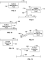
- Figure 8 illustrates a schematic diagram of the additive manufacturing head 116 fixed to a structure 170, according to an example of the present disclosure.
- the additive manufacturing head 116 may be in a fixed position above the powder bed 110.
- the additive manufacturing head 116 may be securely mounted to the structure 170, such as through fasteners, one or more intermediary structures, adhesives, and/or the like.
- the structure 170 may be a wall, ceiling, or the like.
- FIG 9 illustrates a schematic diagram of the additive manufacturing head 116 secured to a mounting assembly 172, according to an example of the present disclosure.
- the mounting assembly 172 includes a base 174 and a mounting arm 176 extending therefrom.
- the base 174 may be supported on a floor 178.
- the additive manufacturing head 116 is secured to a distal end 180 of the mounting arm 176.
- the mounting assembly 172 may be configured to fix the additive manufacturing head 116 above the powder bed 110 (shown in Figure 1 ).
- the mounting assembly 172 may be configured to moveably position the additive manufacturing head 116.
- Figure 10 illustrates a schematic diagram of the additive manufacturing head 116 secured to a track 182, according to an example of the present disclosure.
- the track 182 may be secured to wall, ceiling, floor, and/or the like.
- the track 182 includes rails 184 that retain a moveable portion of the additive manufacturing head 116.
- the additive manufacturing head 116 may include rollers retained within the rails 184. In this manner, the additive manufacturing head 116 may be moveable in relation to the powder bed 110 (shown in Figure 1 ).
- the track 182 may include more or less rails than shown.
- the additive manufacturing head 116 may be moveably coupled to a structure (such as a wall, floor, ceiling, or the like) through other interfaces, such as articulating or telescoping members, wheeled assemblies, and/or the like.
- Figure 11 illustrate a schematic diagram of the additive manufacturing head 116 secured to an articulating arm 188, according to an example of the present disclosure.
- the articulating arm 188 includes one or more moveable segments 190 that allow the additive manufacturing head 116 to be moved through various degrees of freedom.
- the articulating arm 188 may include more or less moveable segments 190 than shown.
- Figure 12 illustrates a schematic diagram of the surface smoothing head 120 fixed to a structure 192, according to an example of the present disclosure.
- the surface smoothing head 120 may be in a fixed position above the powder bed 110.
- the surface smoothing head 120 may be securely mounted to the structure 192, such as through fasteners, one or more intermediary structures, adhesives, and/or the like.
- the structure 192 may be a wall, ceiling, or the like.
- FIG 13 illustrates a schematic diagram of the surface smoothing head 120 secured to a mounting assembly 194, according to an example of the present disclosure.
- the mounting assembly 194 includes a base 196 and a mounting arm 198 extending therefrom.
- the base 196 may be supported on a floor 199.
- the surface smoothing head 120 is secured to a distal end 200 of the mounting arm 198.
- the mounting assembly 194 may be configured to fix the surface smoothing head 120 above the powder bed 110 (shown in Figure 1 ).
- the mounting assembly 194 may be configured to moveably position the surface smoothing head 120.
- Figure 14 illustrates a schematic diagram of the surface smoothing head 120 secured to a track 202, according to an example of the present disclosure.
- the track 202 may be secured to wall, ceiling, floor, and/or the like.
- the track 202 includes rails 204 that retain a moveable portion of the surface smoothing head 120.
- the surface smoothing head 120 may include rollers retained within the rails 204. In this manner, the surface smoothing head 120 may be moveable in relation to the powder bed 110 (shown in Figure 1 ).
- the track 202 may include more or less rails than shown.
- the surface smoothing head 120 may be moveably coupled to a structure (such as a wall, floor, ceiling, or the like) through other interfaces, such as articulating or telescoping members, wheeled assemblies, and/or the like.
- Figure 15 illustrate a schematic diagram of the surface smoothing head 120 secured to an articulating arm 206, according to an example of the present disclosure.
- the articulating arm 206 includes one or more moveable segments 208 that allow the surface smoothing head 120 to be moved through various degrees of freedom.
- the articulating arm 206 may include more or less moveable segments 208 than shown.
- Figure 16 illustrates a schematic diagram of the surface smoothing head 120 coupled to the additive manufacturing head 116, according to an example of the present disclosure.
- a mounting coupling 210 connects the surface smoothing head 120 to the additive manufacturing head 116.
- the mounting coupling 210 may moveably couple the surface smoothing head 120 to the additive manufacturing head 116, such as through articulating arm segments, a moveable carriage, a track, and/or the like.
- the surface smoothing head 120 may be coupled to the additive manufacturing head 116 in a fixed relationship.
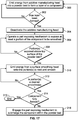
- Figure 17 illustrates a flow chart of an additive manufacturing method, according to an example of the present disclosure.
- the forming control unit 124 may be programmed to operate according to the method shown and described herein.
- energy (such as one or more laser beams) is emitted from the additive manufacturing head 116 into the powder bed 110 to form the layer 128 of the component 114.
- the part exposing mechanism 112 is operated to expose at least a portion 132 of the component 114 to be smoothed.
- the method proceeds to 310, at which energy (such as a focused laser beam) is emitted from the surface smoothing head 120 onto the portion(s) 132 to melt and smooth the portion(s) 132.
- energy such as a focused laser beam
- the method proceeds to 314, at which it is determined whether the component 114 is fully formed. If the component 114 is fully formed, the component 114 is removed from the forming chamber 108, and the method ends at 315. If, however, the component 114 is not fully formed at 314, the method proceeds to 316, at which the part exposing mechanism 112 is engaged to submerge the component 114 back within the powder bed 110. The method then returns to 300.
- an additive manufacturing system that includes a container defining a forming chamber that retains a powder bed (that includes powder), an additive manufacturing head that is configured to emit a first energy into the powder bed to form at least one layer of a component, and a part exposing mechanism on or within the container.
- the part exposing mechanism is configured to operate so that the component is in a first position at a first time within the powder bed, and a second position at a second time in which a portion of the component is exposed outside of the powder bed.
- a surface smoothing head is configured to emit a second energy onto the portion of the component in the second position to smooth the portion of the component.
- a forming control unit is in communication with the additive manufacturing head, the part exposing mechanism, and the surface smoothing head.
- the forming control unit is configured to control (for example, operate) the additive manufacturing head, the part exposing mechanism, and the surface smoothing head.
- the surface smoothing head is coupled to the additive manufacturing head.
- the part exposing mechanism may include an actuation assembly that is configured to move the component upwardly into the second position so that the portion of the component extends upwardly past a top surface of the powder bed.
- the actuation assembly may include a forming bed that supports the component, and an actuator operatively coupled to the forming bed.
- the part exposing mechanism may include a drain assembly that is configured to be selectively moved between a closed position and an open position. At least a first portion of powder drains through the drain assembly in the open position to expose the portion of the component in the second position.
- the drain assembly may include a moveable cover proximate to an outlet formed through a container that retains the powder bed. The moveable cover closes the outlet in the closed position and moves away from the outlet to open the outlet in the open position. At least a first portion of powder drains out of the outlet when the moveable cover is in the open position.
- examples of the present disclosure provide additive manufacturing systems and methods that allow for efficient smoothing of portions of a component. Further, the additive manufacturing systems and methods are configured to expose at least a formed portion of component to be smoothed.
- a structure, limitation, or element that is "configured to” perform a task or operation is particularly structurally formed, constructed, or adapted in a manner corresponding to the task or operation.
- an object that is merely capable of being modified to perform the task or operation is not “configured to” perform the task or operation as used herein.
Landscapes
- Engineering & Computer Science (AREA)
- Chemical & Material Sciences (AREA)
- Materials Engineering (AREA)
- Manufacturing & Machinery (AREA)
- Physics & Mathematics (AREA)
- Optics & Photonics (AREA)
- Mechanical Engineering (AREA)
- Health & Medical Sciences (AREA)
- Toxicology (AREA)
- General Health & Medical Sciences (AREA)
- Plasma & Fusion (AREA)
- Powder Metallurgy (AREA)
Abstract
Description
- Examples of the present disclosure generally relate to additive-manufacturing systems and methods, and more particularly, to systems and methods of smoothing powder bed fusion additively-manufactured components.
- Additive manufacturing systems and methods are used to fabricate components (such as parts or products) through multiple layers of material. For example, known additive manufacturing systems and methods form a component by adding layer-upon-layer of material. Additive manufacturing systems and methods may include or otherwise use three dimensional (3D) modeling (for example, computer-aided design or CAD) software, computer-controlled additive-manufacturing equipment, and raw materials in powder or liquid form.
- Additive manufacturing encompasses a wide variety of technologies and incorporates a wide variety of techniques, such as, for example, laser freeform manufacturing (LFM), laser deposition (LD), direct metal deposition (DMD), laser metal deposition, laser additive manufacturing, laser engineered net shaping (LENS), stereolithography (SLA), selective laser sintering (SLS), fused deposition modeling (FDM), multi jet modeling (MJM), 3D printing, rapid prototyping, direct digital manufacturing, layered manufacturing, and additive fabrication. Moreover, a variety of raw materials may be used in additive manufacturing to create products. Examples of such materials include plastics, metals, concrete, and glass.
- One example of an additive-manufacturing system is a laser additive-manufacturing system. Laser additive manufacturing includes spraying or otherwise injecting a powder or a liquid into a focused beam of a high-power laser or nexus of a plurality of high-powered lasers under controlled atmospheric conditions, thereby creating a weld pool. The resulting deposits may then be used to build or repair articles for a wide variety of applications. The powder injected into the high-power laser beam may include a wide variety of materials such as metal, plastic, and/or the like.
- Articles formed by additive manufacturing may require surface processing to provide a more desirable product. One example of surface processing includes smoothing or otherwise reducing the roughness of the product's surface. Surfaces produced by known additive manufacturing systems and methods may have rough surface finishes, for example, on the order of about 15,24 - 25,4 µm (600-1000 microinches) Ra. Such rough surfaces may have several undesirable effects. For example, components having a rough surface finish have limited applications in cyclical-loading environments due to stress risers typically associated with high surface roughness. Additionally, rough surfaces may impede the use of cost-saving, non-destructive inspection systems because rough surface finishes generate high levels of noise in such systems. When used on parts having relatively smooth surfaces, non-destructive inspection methods are widely recognized as cost-effective and accurate tools for identifying structural deficiencies in such parts.
- To improve the surface finish of a component fabricated with additive-manufacturing equipment, separate post-processing steps are typically undertaken at a processing location using conventional surface-finishing equipment and techniques. However, due to the complexity of some parts, post-processing of surfaces may be cumbersome, expensive, and time consuming. In addition, conventional post-processing surface-finishing methods may be ineffective for reducing the surface roughness of the interior surfaces of some complex parts, resulting in products with less than desirable properties.
- Certain additive manufacturing methods include forming a component with a powder bed of material, such as metal, plastic, and/or the like. Typically, the component is formed within the powder bed. As such, certain known systems and methods of smoothing are unable to be used, as the surrounding material of the powder bed blocks an operative field of a surface processing device. That is, the smoothing laser is unable to emit energy onto a portion to be smoothed, as the portion of the component is embedded or otherwise covered by the powder bed.
- A need exists for an additive manufacturing system and method that allow for efficient smoothing of portions of a component. Further, a need exists for an additive manufacturing system and method that is configured to expose at least a portion of component to be smoothed.
- With those needs in mind, certain examples of the present disclosure provide an additive manufacturing system that includes a powder bed, an additive manufacturing head that is configured to emit a first energy into the powder bed to form at least one layer of a component, a part exposing mechanism that is configured to operate so that the component is in a first position at a first time within the powder bed, and a second position at a second time in which a portion of the component is exposed outside of the powder bed, and a surface smoothing head that is configured to emit a second energy onto the portion of the component in the second position to smooth the portion of the component.
- In at least one example, a container defining a forming chamber. The part exposing mechanism may be on or within the container.
- The additive manufacturing head may be fixed in position. Optionally, the additive manufacturing head may be moveable. In at least one example, the additive manufacturing head is configured to emit the first energy as one or more laser beams.
- The surface smoothing head may be fixed in position. Optionally, the surface smoothing head may be moveable. In at least one example, the surface smoothing head is configured to emit the second energy as one or more laser beams.
- The first energy and the second energy may be the same type of energy (such as laser beams). Alternatively, the first energy may be a different type of energy than the second energy.
- The surface smoothing head may be coupled to the additive manufacturing head. In at least one example, the surface smoothing head may be moveably coupled to the additive manufacturing head.
- A forming control unit may be in communication with the additive manufacturing head, the part exposing mechanism, and the surface smoothing head. The forming control unit may be configured to control the additive manufacturing head, the part exposing mechanism, and the surface smoothing head.
- In at least one example, the part exposing mechanism includes an actuation assembly that is configured to move the component upwardly into the second position so that the portion of the component extends upwardly past a top surface of the powder bed. The actuation assembly may include a forming bed that supports the component, and an actuator operatively coupled to the forming bed. The actuation assembly may also include a motor operatively coupled to the actuator.
- In at least one example, the part exposing mechanism includes a drain assembly that is configured to be selectively moved between a closed position and an open position. At least a first portion of powder drains through the drain assembly in the open position to expose the portion of the component in the second position. The drain assembly may include a moveable cover proximate to an outlet formed through a container that retains the powder bed. The moveable cover closes the outlet in the closed position and moves away from the outlet to open the outlet in the open position. At least some of the powder bed drains out of the outlet when the moveable cover is in the open position.
- Certain examples of the present disclosure provide an additive manufacturing method that includes emitting a first energy from an additive manufacturing head into a powder bed to form at least one layer of a component, operating a part exposing mechanism so that the component is in a first position at a first time within the powder bed, and a second position at a second time in which a portion of the component is exposed outside of the powder bed, and emitting a second energy from a surface smoothing head onto the portion of the component in the second position to smooth the portion of the component.
-
-
Figure 1 illustrates a schematic diagram of an additive manufacturing system, according to an example of the present disclosure. -
Figure 2 illustrates a schematic diagram of a part exposing mechanism, according to an example of the present disclosure. -
Figure 3 illustrates a schematic diagram of a part exposing mechanism, according to an example of the present disclosure. -
Figure 4 illustrates a schematic diagram of an additive manufacturing system in a layer forming state, according to an example of the present disclosure. -
Figure 5 illustrates a schematic diagram of an additive manufacturing system in a component smoothing state, according to an example of the present disclosure. -
Figure 6 illustrates a schematic diagram of an additive manufacturing system in a layer forming state, according to an example of the present disclosure. -
Figure 7 illustrates a schematic diagram of an additive manufacturing system in a component smoothing state, according to an example of the present disclosure. -
Figure 8 illustrates a schematic diagram of an additive manufacturing head fixed to a structure, according to an example of the present disclosure. -
Figure 9 illustrates a schematic diagram of an additive manufacturing head secured to a mounting assembly, according to an example of the present disclosure. -
Figure 10 illustrates a schematic diagram of an additive manufacturing head secured to a track, according to an example of the present disclosure. -
Figure 11 illustrate a schematic diagram of an additive manufacturing head secured to an articulating arm, according to an example of the present disclosure. -
Figure 12 illustrates a schematic diagram of a surface processing head fixed to a structure, according to an example of the present disclosure. -
Figure 13 illustrates a schematic diagram of a surface processing head secured to a mounting assembly, according to an example of the present disclosure. -
Figure 14 illustrates a schematic diagram of a surface processing head secured to a track, according to an example of the present disclosure. -
Figure 15 illustrate a schematic diagram of a surface processing head secured to an articulating arm, according to an example of the present disclosure. -
Figure 16 illustrates a schematic diagram of a surface processing head coupled to an additive manufacturing head, according to an example of the present disclosure. -
Figure 17 illustrates a flow chart of an additive manufacturing method, according to an example of the present disclosure. - The foregoing summary, as well as the following detailed description of certain examples will be better understood when read in conjunction with the appended drawings. As used herein, an element or step recited in the singular and preceded by the word "a" or "an" should be understood as not necessarily excluding the plural of the elements or steps. Further, references to "one example" are not intended to be interpreted as excluding the existence of additional examples that also incorporate the recited features. Moreover, unless explicitly stated to the contrary, examples "comprising" or "having" an element or a plurality of elements having a particular condition may include additional elements not having that condition.
- Certain examples of the present disclosure provide an additive manufacturing system and method that includes a part exposing mechanism that is configured to expose a portion of a component formed within a powder bed through additive manufacturing. In at least one example, the part exposing mechanism includes an actuation assembly that moves at least a portion of the component out of the powder bed after an additive manufacturing head forms at least one layer of the component. In at least one other example, the part exposing mechanism includes a drain assembly that is configured to drain at least a portion of the powder bed out of a forming chamber, thereby exposing at least a portion of the component. When the portion(s) of the component is exposed above a surface of the powder bed, a surface processing head is operated to smooth the portion(s), such as by melting rough surfaces of the portion(s).
- Certain examples of the present disclosure provide an additive-manufacturing system that includes an additive manufacturing head (such as a device for selective laser sintering of a new layer of material on an existing layer of material), and a surface-processing head, which may be coupled to the additive manufacturing head for selective laser sintering. The surface-processing device includes a laser-emitting device configured to emit a laser beam that smooths an adjacent surface of at least one of the new layer of material and the existing layer of material.
- Certain examples of the present disclosure provide a method of additively manufacturing a component. The method includes melting a first layer of powder to generate a build portion and metallic powder, separating the build portion from the unused powder, emitting a laser beam (such as energy emitted from a laser-emitting device) to smooth the build portion and thereby generate a smoothed build portion, positioning the smoothed build portion within the unused powder, and sintering a second layer of metallic powder onto the smoothed build portion.
-
Figure 1 illustrates a schematic diagram of anadditive manufacturing system 100, according to an example of the present disclosure. Theadditive manufacturing system 100 includes acontainer 102 that includes abase 104 andwalls 106 upstanding from thebase 104. Thebase 104 and thewalls 106 define a formingchamber 108. The formingchamber 108 retains apowder bed 110, such as formed of metal, polymer, or other such material. - A
part exposing mechanism 112 is positioned on and/or within thecontainer 102, such as within the formingchamber 108. Thepart exposing mechanism 112 provides a powder bed management system that is configured to expose at least a portion of acomponent 114 during an additive manufacturing process that forms one or more layers of thecomponent 114. - An
additive manufacturing head 116 is fixed in position or moveable in relation to the formingchamber 108. Theadditive manufacturing head 116 includes anenergy emitter 118. In at least one example, theadditive manufacturing head 116 is a laser scanner that emits one or more laser beams through theenergy emitter 118, which may be a laser output, array, and/or the like. Optionally, theadditive manufacturing head 116 may be an electron beam scanner that emits one or more electron beams through theenergy emitter 118, which may be an electron beam output, array, and/or the like. As another example, theadditive manufacturing head 116 may be an arcing scanner that emits electrical arcing energy through theenergy emitter 118, which may be an arcing output, array, and/or the like. United States Patent No.9.751,260 - The
additive manufacturing head 116 is configured to emit energy, such as one or more laser beams, into thepowder bed 110 to form layers of thecomponent 114. For example, theadditive manufacturing head 116 is configured to selectively laser sinter layers of material of thepowder bed 110 onto an existing layer of material to form thecomponent 114. - A
surface smoothing head 120 is fixed in position or moveable in relation to the formingchamber 108. Thesurface smoothing head 120 provides a glazing device that is configured to smooth portions of thecomponent 114 after one or more layers of thecomponent 114 are formed by operation of theadditive manufacturing head 116. Thesurface smoothing head 120 includes anenergy emitter 122. Thesurface smoothing head 120 may be configured to emit the same type of energy as theadditive manufacturing head 116. For example, theadditive manufacturing head 116 may be configured to emit a first energy into thepowder bed 110 to form a layer of thecomponent 114, while thesurface smoothing head 120 is configured to emit a second energy onto an exposed portion of thecomponent 114 to smooth the exposed portion. The first energy and the second energy may be the same type of energy. In at least one other example, the first energy and the second energy may be different types of energy. For example, the first energy may be a laser beam, while the second energy may be an electron beam. - In at least one example, the
surface smoothing head 120 is a laser emitter that emits one or more laser beams through theenergy emitter 122. Optionally, thesurface smoothing head 120 may be an electron beam scanner that emits one or more electron beams through theenergy emitter 122. As another example, thesurface smoothing head 120 may be configured to emit electrical arcing energy through theenergy emitter 122. In at least one example, thesurface smoothing head 120 may be the same as or similar to the surface processing devices described in the 260 Patent. - The
additive manufacturing head 116 may be coupled to thesurface smoothing head 120. For example, thesurface smoothing head 120 may be moveably coupled to theadditive manufacturing head 116, such as through an articulating arm(s), carriage, gantry, tracks, brackets, and/or the like. In at least one other example, thesurface smoothing head 120 is not directly coupled to theadditive manufacturing head 116. - In at least one example, the
additive manufacturing system 100 includes a formingcontrol unit 124, which may be configured to control (for example, operate) theadditive manufacturing system 100. The formingcontrol unit 124 may be in communication with thepart exposing mechanism 112, theadditive manufacturing head 116, and thesurface smoothing head 120, such as through one or more wired or wireless connections. The formingcontrol unit 124 may be configured to operate theadditive manufacturing system 100 through preprogrammed instructions stored in memory. - In operation, the
additive manufacturing head 116 emits energy (such as one or more laser beams) into thepowder bed 110 to form alayer 128 of thecomponent 114. For example, theadditive manufacturing head 116 selectively laser sinters thelayer 128 from material within thepowder bed 110 onto an existinglayer 130 of thecomponent 114. The formingcontrol unit 124 may control theadditive manufacturing head 116 during the forming process. - After the
layer 128 of thecomponent 114 has been formed by theadditive manufacturing head 116 emitting energy into thepowder bed 110, thepart exposing mechanism 112 is operated to expose at least aportion 132 of thecomponent 114 out of thepowder bed 110. Theportion 132 may be an edge of thecomponent 114. Theportion 132 may be half or more of thecomponent 114. In at least one other example, theportion 132 may be an entirety of the component. In at least one example, the formingcontrol unit 124 operates thepart exposing mechanism 112 to expose the portion(s) 132 of thecomponent 114 out of thepowder bed 110. The portion(s) 132 may be the layer 128 (or at least a portion thereof) that was previously formed by theadditive manufacturing head 116 emitting energy into thepowder bed 110. - After the portion(s) 132 is exposed outside of the
powder bed 110, thesurface smoothing head 120 may be operated to melt rough surface portions of the portion(s) 132, which may include portions of thelayer 128, the existinglayer 130, and/or various other portions of thecomponent 114. For example, the formingcontrol unit 124 may control operation of thesurface smoothing head 120 to emit energy (such as a laser beam) to smooth the portion(s) 132 outside of thepowder bed 110. After the portion(s) 132 has been smoothed by thesurface smoothing head 120, thepart exposing mechanism 112 is operated to move thecomponent 114 back into thepowder bed 110 so that thecomponent 114 is submerged therein or otherwise covered thereby. In at least one example, additional material may be added to thepowder bed 110 to submerge thecomponent 114 therein. When thecomponent 114 is submerged within or otherwise covered by thepowder bed 110, the process may repeat, such that theadditive manufacturing head 116 emits energy into thepowder bed 110 to form another layer over thelayer 128, after which thepart exposing mechanism 112 is operated to expose at least a portion of thecomponent 114 to be smoothed by thesurface smoothing head 120. The process continues to repeat until all layers of thecomponent 114 are formed, and all portions that are to be smoothed by thesurface smoothing head 120 are smoothed. - As described, examples of the present disclosure provide the
additive manufacturing system 100 that includes thepowder bed 110, theadditive manufacturing head 116 that is configured to emit a first energy (such as one or more laser beams) into thepowder bed 110 to form at least onelayer 128 of thecomponent 114, thepart exposing mechanism 112 that is configured to operate so that thecomponent 114 is in a first position (such as a covered or submerged position) at a first time within thepowder bed 110, and a second position at a second time (such as after the first time) in which theportion 132 of thecomponent 114 is exposed outside of thepowder bed 110, and thesurface smoothing head 120 that is configured to emit a second energy (such as one or more laser beams) onto theportion 132 of thecomponent 114 in the second position to smooth theportion 132 of thecomponent 114. - In at least one example, the
part exposing mechanism 112 is or otherwise includes an actuation assembly that moves thecomponent 114 upwardly within the formingchamber 108 such that the portion(s) 132 is exposed above atop surface 134 of thepowder bed 110. In at least one other example, thepart exposing mechanism 112 is or otherwise includes a drain assembly that is configured to be selectively closed and opened. In the open position, a portion of thepowder bed 110 drains out of the formingchamber 108, until theportion 132 is exposed above thetop surface 134. - As used herein, the term "control unit," "central processing unit," "unit," "CPU," "computer," or the like may include any processor-based or microprocessor-based system including systems using microcontrollers, reduced instruction set computers (RISC), application specific integrated circuits (ASICs), logic circuits, and any other circuit or processor including hardware, software, or a combination thereof capable of executing the functions described herein. Such are exemplary only and are thus not intended to limit in any way the definition and/or meaning of such terms. For example, the forming
control unit 124 may be or include one or more processors that are configured to control operation of theadditive manufacturing system 100, as described herein. - The forming
control unit 124 is configured to execute a set of instructions that are stored in one or more data storage units or elements (such as one or more memories), in order to process data. For example, the formingcontrol unit 124 may include or be coupled to one or more memories. The data storage units may also store data or other information as desired or needed. The data storage units may be in the form of an information source or a physical memory element within a processing machine. - The set of instructions may include various commands that instruct the forming
control unit 124 as a processing machine to perform specific operations such as the methods and processes of the various examples of the subject matter described herein. The set of instructions may be in the form of a software program. The software may be in various forms such as system software or application software. Further, the software may be in the form of a collection of separate programs, a program subset within a larger program or a portion of a program. The software may also include modular programming in the form of object-oriented programming. The processing of input data by the processing machine may be in response to user commands, or in response to results of previous processing, or in response to a request made by another processing machine. - The diagrams of examples herein may illustrate one or more control or processing units, such as the forming
control unit 124. It is to be understood that the processing or control units may represent circuits, circuitry, or portions thereof that may be implemented as hardware with associated instructions (e.g., software stored on a tangible and non-transitory computer readable storage medium, such as a computer hard drive, ROM, RAM, or the like) that perform the operations described herein. The hardware may include state machine circuitry hardwired to perform the functions described herein. Optionally, the hardware may include electronic circuits that include and/or are connected to one or more logic-based devices, such as microprocessors, processors, controllers, or the like. Optionally, the formingcontrol unit 124 may represent processing circuitry such as one or more of a field programmable gate array (FPGA), application specific integrated circuit (ASIC), microprocessor(s), and/or the like. The circuits in various examples may be configured to execute one or more algorithms to perform functions described herein. The one or more algorithms may include aspects of examples disclosed herein, whether or not expressly identified in a flowchart or a method. - As used herein, the terms "software" and "firmware" are interchangeable, and include any computer program stored in a data storage unit (for example, one or more memories) for execution by a computer, including RAM memory, ROM memory, EPROM memory, EEPROM memory, and non-volatile RAM (NVRAM) memory. The above data storage unit types are exemplary only and are thus not limiting as to the types of memory usable for storage of a computer program.
-
Figure 2 illustrates a schematic diagram of thepart exposing mechanism 112, according to an example of the present disclosure. In this example, thepart exposing mechanism 112 is anactuation assembly 135 that includes a formingbed 136 and anactuator 138 operatively coupled to the formingbed 136. Amotor 140 is operatively coupled to theactuator 138. - Referring to
Figures 1 and 2 , thecomponent 114 is supported on atop surface 142 of the formingbed 136. Theactuator 138 may be or include one or more electric, pneumatic, hydraulic, and/or the like pistons, cams, lift brackets, and/or the like that are moved by themotor 140. Themotor 140 is activated to move theactuator 138 and selectively lift and lower the formingbed 136, and therefore thecomponent 114, upwardly and downwardly in relation to thepowder bed 110. Optionally, theactuator 138 may include an integral motor or other form of powered actuation, instead of being coupled to a separate and distinct motor. The formingcontrol unit 124 may be in communication with themotor 140, such as through one or more wired or wireless connections, to control operation of thepart exposing mechanism 112. In at least one other example, the actuation assembly may include a vibratory device or the like that is configured to shake power bed material off thecomponent 114. -
Figure 3 illustrates a schematic diagram of thepart exposing mechanism 112, according to an example of the present disclosure. In this example, thepart exposing mechanism 112 is adrain assembly 144 coupled to a portion of thecontainer 102. For example, thedrain assembly 144 may be secured to thebase 104 of thecontainer 102. In at least one other example, thedrain assembly 144 may be secured to a wall 106 (shown inFigure 1 ) of thecontainer 102 below thetop surface 134 of thepowder bed 110. - The
drain assembly 144 includes amoveable cover 146 proximate to an outlet 148 (such as an opening) formed through thecontainer 102. Thecover 146 is moveably coupled to an actuator 150 (such as a moveable hinge, post, or the like). In a closed position, thecover 146 closes theoutlet 148. For example, in the closed position, thecover 146 may be positioned below, over, or within theoutlet 148 to prevent material from draining out of theoutlet 148. In an open position, theactuator 150 moves thecover 146 away from theoutlet 148, thereby allowing material to drain out of theoutlet 148. The formingcontrol unit 124 may be in communication with theactuator 150, such as through one or more wired or wireless connections, to control operation of thepart exposing mechanism 112. -
Figure 4 illustrates a schematic diagram of theadditive manufacturing system 100 in a layer forming state, according to an example of the present disclosure. As shown, thecomponent 114 is supported on the forming bed 136 (such as a plate) within the formingchamber 108. In the layer forming state, thepart exposing mechanism 112 is in a first position, in which theactuators 138 are retracted. In the layer forming state, thecomponent 114 is submerged within or otherwise covered by thepowder bed 110. No portion of thecomponent 114 may be exposed above thetop surface 134 during the layer forming stage. - During the layer forming state, the
additive manufacturing head 116 emits a first energy 151 (such as one or more laser beams) into thepowder bed 110 to form a layer of thecomponent 114, as described herein. Thesurface smoothing head 120 is outside of anenergy emission envelope 152 of theadditive manufacturing head 116 during the layer forming state. After a desired layer of thecomponent 114 has been formed by theadditive manufacturing head 116 emitting thefirst energy 151 into thepowder bed 110, thepart exposing mechanism 112 is operated to move theportion 132 of thecomponent 114 above thetop surface 134 of thepowder bed 110. -
Figure 5 illustrates a schematic diagram of theadditive manufacturing system 100 in a component smoothing state, according to an example of the present disclosure. As shown, in the component smoothing state, thepart exposing mechanism 112 is in a second position, in which theactuators 138 are extended to move thecomponent 114 upwardly through thepowder bed 110. In the component smoothing state, theadditive manufacturing head 116 is deactivated, and theactuators 138 are moved to urge the portion(s) 132 above thetop surface 134 of thepowder bed 110. As such, thesurface smoothing head 120 may then be moved into a desired position to emit focused energy, or second energy, 154 (such as a focused laser beam) onto the portion(s) 132 of thecomponent 114 to melt and thereby smooth the portion(s) 132.Excess powder 156 may overflow the formingchamber 108 as thepart exposing mechanism 112 moves thecomponent 114 upwardly within the formingchamber 108. Theexcess powder 156 may be deposited back into the formingchamber 108. -
Figure 6 illustrates a schematic diagram of theadditive manufacturing system 100 in a layer forming state, according to an example of the present disclosure. In the layer forming state, thedrain assembly 144 is in a first position, such as a closed position, thereby ensuring that material within thepowder bed 110 remains in the forming chamber. -
Figure 7 illustrates a schematic diagram of theadditive manufacturing system 100 in a component smoothing state, according to an example of the present disclosure. In the component smoothing state, thedrain assembly 144 is moved into a second position, such as an open position, thereby allowing anunused portion 160 of thepowder bed 110 to drain out of the formingchamber 108. As theunused portion 160 drains out of the formingchamber 108, the portion(s) 132 of thecomponent 114 is exposed above thetop surface 134 of thepowder bed 110 within the formingchamber 108. The portion(s) 132 may then be smoothed by thesurface smoothing head 120, as described herein. - Optionally, the examples shown in
Figures 4-7 may be combined into a single example. For example, theadditive manufacturing system 100 may include an actuation system, which may include theactuators 138 shown inFigures 4 and 5 , and thedrain assembly 144 shown inFigures 6 and 7 . -
Figure 8 illustrates a schematic diagram of theadditive manufacturing head 116 fixed to astructure 170, according to an example of the present disclosure. Referring toFigures 1 and8 , theadditive manufacturing head 116 may be in a fixed position above thepowder bed 110. For example, theadditive manufacturing head 116 may be securely mounted to thestructure 170, such as through fasteners, one or more intermediary structures, adhesives, and/or the like. Thestructure 170 may be a wall, ceiling, or the like. -
Figure 9 illustrates a schematic diagram of theadditive manufacturing head 116 secured to a mountingassembly 172, according to an example of the present disclosure. The mountingassembly 172 includes abase 174 and a mountingarm 176 extending therefrom. The base 174 may be supported on afloor 178. Theadditive manufacturing head 116 is secured to adistal end 180 of the mountingarm 176. The mountingassembly 172 may be configured to fix theadditive manufacturing head 116 above the powder bed 110 (shown inFigure 1 ). Optionally, the mountingassembly 172 may be configured to moveably position theadditive manufacturing head 116. -
Figure 10 illustrates a schematic diagram of theadditive manufacturing head 116 secured to atrack 182, according to an example of the present disclosure. Thetrack 182 may be secured to wall, ceiling, floor, and/or the like. Thetrack 182 includesrails 184 that retain a moveable portion of theadditive manufacturing head 116. For example, theadditive manufacturing head 116 may include rollers retained within therails 184. In this manner, theadditive manufacturing head 116 may be moveable in relation to the powder bed 110 (shown inFigure 1 ). Thetrack 182 may include more or less rails than shown. Theadditive manufacturing head 116 may be moveably coupled to a structure (such as a wall, floor, ceiling, or the like) through other interfaces, such as articulating or telescoping members, wheeled assemblies, and/or the like. -
Figure 11 illustrate a schematic diagram of theadditive manufacturing head 116 secured to an articulatingarm 188, according to an example of the present disclosure. The articulatingarm 188 includes one or moremoveable segments 190 that allow theadditive manufacturing head 116 to be moved through various degrees of freedom. The articulatingarm 188 may include more or lessmoveable segments 190 than shown. -
Figure 12 illustrates a schematic diagram of thesurface smoothing head 120 fixed to astructure 192, according to an example of the present disclosure. Referring toFigures 1 and12 , thesurface smoothing head 120 may be in a fixed position above thepowder bed 110. For example, thesurface smoothing head 120 may be securely mounted to thestructure 192, such as through fasteners, one or more intermediary structures, adhesives, and/or the like. Thestructure 192 may be a wall, ceiling, or the like. -
Figure 13 illustrates a schematic diagram of thesurface smoothing head 120 secured to a mountingassembly 194, according to an example of the present disclosure. The mountingassembly 194 includes abase 196 and a mountingarm 198 extending therefrom. The base 196 may be supported on afloor 199. Thesurface smoothing head 120 is secured to adistal end 200 of the mountingarm 198. The mountingassembly 194 may be configured to fix thesurface smoothing head 120 above the powder bed 110 (shown inFigure 1 ). Optionally, the mountingassembly 194 may be configured to moveably position thesurface smoothing head 120. -
Figure 14 illustrates a schematic diagram of thesurface smoothing head 120 secured to atrack 202, according to an example of the present disclosure. Thetrack 202 may be secured to wall, ceiling, floor, and/or the like. Thetrack 202 includesrails 204 that retain a moveable portion of thesurface smoothing head 120. For example, thesurface smoothing head 120 may include rollers retained within therails 204. In this manner, thesurface smoothing head 120 may be moveable in relation to the powder bed 110 (shown inFigure 1 ). Thetrack 202 may include more or less rails than shown. Thesurface smoothing head 120 may be moveably coupled to a structure (such as a wall, floor, ceiling, or the like) through other interfaces, such as articulating or telescoping members, wheeled assemblies, and/or the like. -
Figure 15 illustrate a schematic diagram of thesurface smoothing head 120 secured to an articulatingarm 206, according to an example of the present disclosure. The articulatingarm 206 includes one or moremoveable segments 208 that allow thesurface smoothing head 120 to be moved through various degrees of freedom. The articulatingarm 206 may include more or lessmoveable segments 208 than shown. -
Figure 16 illustrates a schematic diagram of thesurface smoothing head 120 coupled to theadditive manufacturing head 116, according to an example of the present disclosure. A mountingcoupling 210 connects thesurface smoothing head 120 to theadditive manufacturing head 116. For example, the mountingcoupling 210 may moveably couple thesurface smoothing head 120 to theadditive manufacturing head 116, such as through articulating arm segments, a moveable carriage, a track, and/or the like. In at least one other example, thesurface smoothing head 120 may be coupled to theadditive manufacturing head 116 in a fixed relationship. -
Figure 17 illustrates a flow chart of an additive manufacturing method, according to an example of the present disclosure. Referring toFigures 1 and17 , the formingcontrol unit 124 may be programmed to operate according to the method shown and described herein. - At 300, energy (such as one or more laser beams) is emitted from the
additive manufacturing head 116 into thepowder bed 110 to form thelayer 128 of thecomponent 114. At 302, it is determined whether thelayer 128 has been fully formed. If not, the process returns to 300. The process may continue to loop between 300 and 302 until the layer or layers have been formed to a desired depth, height, or the like. If, however, thelayer 128 has been fully formed at 302, the method proceeds to 304, at which theadditive manufacturing head 116 is deactivated. - At 306, the
part exposing mechanism 112 is operated to expose at least aportion 132 of thecomponent 114 to be smoothed. At 308, it is determined whether the portion(s) 132 is exposed above thetop surface 134 of thepowder bed 110. If not, the method returns to 306, at which the part exposing mechanism continues to be operated to expose the portion(s) 132. - If, however, the portion(s) 132 is exposed above the
top surface 134 of thepowder bed 110 at 308, the method proceeds to 310, at which energy (such as a focused laser beam) is emitted from thesurface smoothing head 120 onto the portion(s) 132 to melt and smooth the portion(s) 132. At 312, it is determined whether the portion(s) 132 is a desired smoothness. If not, the method returns to 310, at which the energy continues to be emitted from thesurface smoothing head 120 onto the portion(s) 132. - If, however, the portion(s) 132 is a desired smoothness at 312, the method proceeds to 314, at which it is determined whether the
component 114 is fully formed. If thecomponent 114 is fully formed, thecomponent 114 is removed from the formingchamber 108, and the method ends at 315. If, however, thecomponent 114 is not fully formed at 314, the method proceeds to 316, at which thepart exposing mechanism 112 is engaged to submerge thecomponent 114 back within thepowder bed 110. The method then returns to 300. - As described herein, certain examples of the present disclosure provide an additive manufacturing system that includes a container defining a forming chamber that retains a powder bed (that includes powder), an additive manufacturing head that is configured to emit a first energy into the powder bed to form at least one layer of a component, and a part exposing mechanism on or within the container. The part exposing mechanism is configured to operate so that the component is in a first position at a first time within the powder bed, and a second position at a second time in which a portion of the component is exposed outside of the powder bed. A surface smoothing head is configured to emit a second energy onto the portion of the component in the second position to smooth the portion of the component. A forming control unit is in communication with the additive manufacturing head, the part exposing mechanism, and the surface smoothing head. The forming control unit is configured to control (for example, operate) the additive manufacturing head, the part exposing mechanism, and the surface smoothing head. In at least one example, the surface smoothing head is coupled to the additive manufacturing head.
- The part exposing mechanism may include an actuation assembly that is configured to move the component upwardly into the second position so that the portion of the component extends upwardly past a top surface of the powder bed. The actuation assembly may include a forming bed that supports the component, and an actuator operatively coupled to the forming bed.
- The part exposing mechanism may include a drain assembly that is configured to be selectively moved between a closed position and an open position. At least a first portion of powder drains through the drain assembly in the open position to expose the portion of the component in the second position. The drain assembly may include a moveable cover proximate to an outlet formed through a container that retains the powder bed. The moveable cover closes the outlet in the closed position and moves away from the outlet to open the outlet in the open position. At least a first portion of powder drains out of the outlet when the moveable cover is in the open position.
- As described herein, examples of the present disclosure provide additive manufacturing systems and methods that allow for efficient smoothing of portions of a component. Further, the additive manufacturing systems and methods are configured to expose at least a formed portion of component to be smoothed.
- While various spatial and directional terms, such as top, bottom, lower, mid, lateral, horizontal, vertical, front and the like may be used to describe examples of the present disclosure, it is understood that such terms are merely used with respect to the orientations shown in the drawings. The orientations may be inverted, rotated, or otherwise changed, such that an upper portion is a lower portion, and vice versa, horizontal becomes vertical, and the like.
- As used herein, a structure, limitation, or element that is "configured to" perform a task or operation is particularly structurally formed, constructed, or adapted in a manner corresponding to the task or operation. For purposes of clarity and the avoidance of doubt, an object that is merely capable of being modified to perform the task or operation is not "configured to" perform the task or operation as used herein.
It is to be understood that the above description is intended to be illustrative, and not restrictive. For example, the above-described examples (and/or aspects thereof) may be used in combination with each other. In addition, many modifications may be made to adapt a particular situation or material to the teachings of the various examples of the disclosure without departing from their scope. While the dimensions and types of materials described herein are intended to define the parameters of the various examples of the disclosure, the examples are by no means limiting and are exemplary examples. Many other examples will be apparent to those of skill in the art upon reviewing the above description. The scope of the various examples of the disclosure should, therefore, be determined with reference to the appended claims, along with the full scope of equivalents to which such claims are entitled. In the appended claims, the terms "including" and "in which" are used as the plain-English equivalents of the respective terms "comprising" and "wherein." Moreover, the terms "first," "second," and "third," etc. are used merely as labels, and are not intended to impose numerical requirements on their objects. - Further, the disclosure comprises examples according to the following clauses:
- Clause 1. An additive manufacturing system (100) comprising:
- a powder bed (110);
- an additive manufacturing head (116) that is configured to emit a first energy (151) into the powder bed (110) to form at least one layer (128, 130) of a component (114);
- a part exposing mechanism (112) that is configured to operate so that the component (114) is in a first position at a first time within the powder bed (110), and a second position at a second time in which a portion (132) of the component (114) is exposed outside of the powder bed (110); and
- a surface smoothing head (120) that is configured to emit a second energy (154) onto the portion (132) of the component (114) in the second position to smooth the portion (132) of the component (114).
- Clause 2. The additive manufacturing system (100) of Clause 1, further comprising a container (102) defining a forming chamber (108).
- Clause 3. The additive manufacturing system (100) of Clause 2, wherein the part exposing mechanism (112) is on or within the container (102).
- Clause 4. The additive manufacturing system (100) of any one of Clauses 1-3, wherein the additive manufacturing head (116) is one of fixed in position, or moveable.
- Clause 5. The additive manufacturing system (100) of any one of Clauses 1-4, wherein the additive manufacturing head (116) is configured to emit the first energy (151) as one or more laser beams.
- Clause 6. The additive manufacturing system (100) of any one of Clauses 1-5, wherein the surface smoothing head (120) is one of fixed in position or moveable.
- Clause 7. The additive manufacturing system (100) of any one of Clauses 1-6, wherein the surface smoothing head (120) is configured to emit the second energy (154) as one or more laser beams.
- Clause 8. The additive manufacturing system (100) of any one of Clauses 1-7, wherein the first energy (151) and the second energy (154) are the same type of energy, or wherein the first energy (151) is a different type of energy that the second energy (154).
- Clause 9. The additive manufacturing system (100) of any one of Clauses 1-8, wherein the surface smoothing head (120) is coupled to the additive manufacturing head (116).
- Clause 10. The additive manufacturing system (100) of Clause 9, wherein the surface smoothing head (120) is moveably coupled to the additive manufacturing head (116).
- Clause 11. The additive manufacturing system (100) of any one of Clauses 1-10, further comprising a forming control unit (124) in communication with the additive manufacturing head (116), the part exposing mechanism (112), and the surface smoothing head (120), wherein the forming control unit (124) is configured to operate the additive manufacturing head (116), the part exposing mechanism (112), and the surface smoothing head (120).
- Clause 12. The additive manufacturing system (100) of any one of Clauses 1-11, wherein the part exposing mechanism (112) comprises an actuation assembly (135) that is configured to move the component (114) upwardly into the second position so that the portion (132) of the component (114) extends upwardly past a top surface (134, 142) of the powder bed (110).
- Clause 13. The additive manufacturing system (100) of Clause 12, wherein the actuation assembly (135) comprises a forming bed (136) that supports the component (114), and an actuator (138, 150) operatively coupled to the forming bed (136).
- Clause 14. The additive manufacturing system (100) of any one of Clauses 1-13, wherein the part exposing mechanism (112) comprises a drain assembly (144) that is configured to be selectively moved between a closed position and an open position, wherein at least a first portion (132) of powder drains through the drain assembly (144) in the open position to expose the portion (132) of the component (114) in the second position.
- Clause 15. The additive manufacturing system (100) of Clause 14, wherein the drain assembly (144) comprises a moveable cover (146) proximate to an outlet (148) formed through a container (102) that retains the powder bed (110), wherein the moveable cover (146) is configured to close the outlet (148) in the closed position, and moves away from the outlet (148) to open the outlet (148) in the open position, and wherein at least some of the powder bed (110) drains out of the outlet (148) when the moveable cover (146) is in the open position.
- Clause 16. An additive manufacturing method comprising:
- emitting a first energy (151) from an additive manufacturing head (116) into a powder bed (110) to form at least one layer (128, 130) of a component (114);
- operating a part exposing mechanism (112) so that the component (114) is in a first position at a first time within the powder bed (110), and a second position at a second time in which a portion (132) of the component (114) is exposed outside of the powder bed (110); and
- emitting a second energy (154) from a surface smoothing head (120) onto the portion (132) of the component (114) in the second position to smooth the portion (132) of the component (114).
- Clause 17. The additive manufacturing method of Clause 16, wherein the operating comprises using an actuation assembly (135) that moves the component (114) upwardly into the second position so that the portion (132) of the component (114) extends upwardly past a top surface (134, 142) of the powder bed (110).
- Clause 18. The additive manufacturing method of Clause 16 or 17, wherein the operating further comprises supporting the component (114) on a forming bed (136) that is operatively coupled to an actuator (138, 150).
- Clause 19. The additive manufacturing method of any one of Clauses 16-18, wherein the operating comprises selectively moving a drain assembly (144) between a closed position and an open position, wherein at least a first portion (132) of powder of the powder bed (110) drains through the drain assembly (144) in the open position to expose the portion (132) of the component (114) in the second position.
- Clause 20. The additive manufacturing method of Clause 19, wherein the operating comprises:
- closing an outlet (148) through a container (102) that retains the powder bed (110) with a moveable cover (146) in the closed position; and
- moving the moveable cover (146) away from the outlet (148) to open the outlet (148) in the open position, wherein at least a first portion (132) of powder drains out of the outlet (148) when the moveable cover (146) is in the open position.
- This written description uses examples to disclose the various examples of the disclosure, including the best mode, and also to enable any person skilled in the art to practice the various examples of the disclosure, including making and using any devices or systems and performing any incorporated methods. The patentable scope of the various examples of the disclosure is defined by the claims, and may include other examples that occur to those skilled in the art. Such other examples are intended to be within the scope of the claims if the examples have structural elements that do not differ from the literal language of the claims, or if the examples include equivalent structural elements with insubstantial differences from the literal language of the claims.
Claims (15)
- An additive manufacturing system (100) comprising:a powder bed (110);an additive manufacturing head (116) that is configured to emit a first energy (151) into the powder bed (110) to form at least one layer (128, 130) of a component (114);a part exposing mechanism (112) that is configured to operate so that the component (114) is in a first position at a first time within the powder bed (110), and a second position at a second time in which a portion (132) of the component (114) is exposed outside of the powder bed (110); anda surface smoothing head (120) that is configured to emit a second energy (154) onto the portion (132) of the component (114) in the second position to smooth the portion (132) of the component (114).
- The additive manufacturing system (100) of claim 1, further comprising a container (102) defining a forming chamber (108), and wherein the part exposing mechanism (112) is on or within the container (102).
- The additive manufacturing system (100) of claim 1 or 2, wherein the additive manufacturing head (116) is configured to emit the first energy (151) as one or more laser beams.
- The additive manufacturing system (100) of any one of claims 1-3, wherein the surface smoothing head (120) is configured to emit the second energy (154) as one or more laser beams.
- The additive manufacturing system (100) of any one of claims 1-4, wherein the first energy (151) and the second energy (154) are the same type of energy, or wherein the first energy (151) is a different type of energy that the second energy (154).
- The additive manufacturing system (100) of any one of claims 1-5, wherein the surface smoothing head (120) is either coupled or moveably coupled to the additive manufacturing head (116).
- The additive manufacturing system (100) of any one of claims 1-6, further comprising a forming control unit (124) in communication with the additive manufacturing head (116), the part exposing mechanism (112), and the surface smoothing head (120), wherein the forming control unit (124) is configured to operate the additive manufacturing head (116), the part exposing mechanism (112), and the surface smoothing head (120).
- The additive manufacturing system (100) of any one of claims 1-7, wherein the part exposing mechanism (112) comprises an actuation assembly (135) that is configured to move the component (114) upwardly into the second position so that the portion (132) of the component (114) extends upwardly past a top surface (134, 142) of the powder bed (110).
- The additive manufacturing system (100) of claim 8, wherein the actuation assembly (135) comprises a forming bed (136) that supports the component (114), and an actuator (138, 150) operatively coupled to the forming bed (136).
- The additive manufacturing system (100) of any one of claims 1-9, wherein the part exposing mechanism (112) comprises a drain assembly (144) that is configured to be selectively moved between a closed position and an open position, wherein at least a first portion (132) of powder drains through the drain assembly (144) in the open position to expose the portion (132) of the component (114) in the second position.
- The additive manufacturing system (100) of claim 10, wherein the drain assembly (144) comprises a moveable cover (146) proximate to an outlet (148) formed through a container (102) that retains the powder bed (110), wherein the moveable cover (146) is configured to close the outlet (148) in the closed position, and moves away from the outlet (148) to open the outlet (148) in the open position, and wherein at least some of the powder bed (110) drains out of the outlet (148) when the moveable cover (146) is in the open position.
- An additive manufacturing method comprising:emitting a first energy (151) from an additive manufacturing head (116) into a powder bed (110) to form at least one layer (128, 130) of a component (114);operating a part exposing mechanism (112) so that the component (114) is in a first position at a first time within the powder bed (110), and a second position at a second time in which a portion (132) of the component (114) is exposed outside of the powder bed (110); andemitting a second energy (154) from a surface smoothing head (120) onto the portion (132) of the component (114) in the second position to smooth the portion (132) of the component (114).
- The additive manufacturing method of claim 12, wherein the operating comprises using an actuation assembly (135) that moves the component (114) upwardly into the second position so that the portion (132) of the component (114) extends upwardly past a top surface (134, 142) of the powder bed (110).
- The additive manufacturing method of claim 12 or 13, wherein the operating further comprises supporting the component (114) on a forming bed (136) that is operatively coupled to an actuator (138, 150).
- The additive manufacturing method of any one of claims 12-14, wherein the operating comprises selectively moving a drain assembly (144) between a closed position and an open position, wherein at least a first portion (132) of powder of the powder bed (110) drains through the drain assembly (144) in the open position to expose the portion (132) of the component (114) in the second position, and wherein the operating further comprises:closing an outlet (148) through a container (102) that retains the powder bed (110) with a moveable cover (146) in the closed position; andmoving the moveable cover (146) away from the outlet (148) to open the outlet (148) in the open position, wherein at least a first portion (132) of powder drains out of the outlet (148) when the moveable cover (146) is in the open position.
Applications Claiming Priority (1)
| Application Number | Priority Date | Filing Date | Title |
|---|---|---|---|
| US16/035,795 US12214547B2 (en) | 2018-07-16 | 2018-07-16 | Additive-manufacturing systems and methods |
Publications (2)
| Publication Number | Publication Date |
|---|---|
| EP3597400A1 true EP3597400A1 (en) | 2020-01-22 |
| EP3597400B1 EP3597400B1 (en) | 2025-12-31 |
Family
ID=66999620
Family Applications (1)
| Application Number | Title | Priority Date | Filing Date |
|---|---|---|---|
| EP19181287.4A Active EP3597400B1 (en) | 2018-07-16 | 2019-06-19 | SYSTEMS AND METHODS FOR GENERATIVE MANUFACTURING |
Country Status (5)
| Country | Link |
|---|---|
| US (1) | US12214547B2 (en) |
| EP (1) | EP3597400B1 (en) |
| JP (1) | JP7471060B2 (en) |
| CN (1) | CN110722794B (en) |
| CA (1) | CA3046734C (en) |
Cited By (2)
| Publication number | Priority date | Publication date | Assignee | Title |
|---|---|---|---|---|
| DE102020128028A1 (en) | 2020-10-23 | 2022-04-28 | Kurtz Gmbh | Device for the additive manufacturing of components, in particular by means of selective melting or sintering |
| US20240207941A1 (en) * | 2020-03-23 | 2024-06-27 | Kurtz Gmbh & Co. Kg | Device for the Generative Manufacturing of Components, in Particular by Means of Selective Melting or Sintering |
Families Citing this family (1)
| Publication number | Priority date | Publication date | Assignee | Title |
|---|---|---|---|---|
| US12042862B2 (en) * | 2022-09-22 | 2024-07-23 | The Boeing Company | Systems and methods for refining additively manufactured components |
Citations (3)
| Publication number | Priority date | Publication date | Assignee | Title |
|---|---|---|---|---|
| US20170252860A1 (en) * | 2016-03-07 | 2017-09-07 | MTU Aero Engines AG | Micro-forging by a generative manufacturing process |
| US9833955B2 (en) * | 2012-07-09 | 2017-12-05 | Exone Gmbh | Method and device for unpacking a component |
| US20180126634A1 (en) * | 2016-11-10 | 2018-05-10 | MTU Aero Engines AG | Method for enhancing the finish of additively-manufactured components |
Family Cites Families (10)
| Publication number | Priority date | Publication date | Assignee | Title |
|---|---|---|---|---|
| JP3446618B2 (en) | 1998-08-26 | 2003-09-16 | 松下電工株式会社 | Surface finishing method for metal powder sintered parts |
| JP2001334583A (en) * | 2000-05-25 | 2001-12-04 | Minolta Co Ltd | 3D modeling equipment |
| JP3943315B2 (en) | 2000-07-24 | 2007-07-11 | 松下電工株式会社 | Manufacturing method of three-dimensional shaped object |
| DE10158169B4 (en) | 2001-11-28 | 2007-02-08 | Cl Schutzrechtsverwaltungs Gmbh | Device for producing and / or processing components made of powder particles |
| DE202011003443U1 (en) * | 2011-03-02 | 2011-12-23 | Bego Medical Gmbh | Device for the generative production of three-dimensional components |
| US9751260B2 (en) | 2013-07-24 | 2017-09-05 | The Boeing Company | Additive-manufacturing systems, apparatuses and methods |
| JP2015189024A (en) | 2014-03-27 | 2015-11-02 | セイコーエプソン株式会社 | Manufacturing method of shaped objects |
| US9346127B2 (en) * | 2014-06-20 | 2016-05-24 | Velo3D, Inc. | Apparatuses, systems and methods for three-dimensional printing |
| WO2017044892A1 (en) | 2015-09-11 | 2017-03-16 | Autodesk, Inc. | Multi-tool manufacturing system |
| FR3041278B1 (en) | 2015-09-23 | 2017-11-03 | Manutech-Usd | SYSTEM AND METHOD FOR ADDITIVE FABRICATION BY LASER FUSION OF A BED OF POWDER |
-
2018
- 2018-07-16 US US16/035,795 patent/US12214547B2/en active Active
-
2019
- 2019-06-14 CA CA3046734A patent/CA3046734C/en active Active
- 2019-06-19 EP EP19181287.4A patent/EP3597400B1/en active Active
- 2019-07-04 CN CN201910597003.0A patent/CN110722794B/en active Active
- 2019-07-16 JP JP2019130794A patent/JP7471060B2/en active Active
Patent Citations (3)
| Publication number | Priority date | Publication date | Assignee | Title |
|---|---|---|---|---|
| US9833955B2 (en) * | 2012-07-09 | 2017-12-05 | Exone Gmbh | Method and device for unpacking a component |
| US20170252860A1 (en) * | 2016-03-07 | 2017-09-07 | MTU Aero Engines AG | Micro-forging by a generative manufacturing process |
| US20180126634A1 (en) * | 2016-11-10 | 2018-05-10 | MTU Aero Engines AG | Method for enhancing the finish of additively-manufactured components |
Cited By (2)
| Publication number | Priority date | Publication date | Assignee | Title |
|---|---|---|---|---|
| US20240207941A1 (en) * | 2020-03-23 | 2024-06-27 | Kurtz Gmbh & Co. Kg | Device for the Generative Manufacturing of Components, in Particular by Means of Selective Melting or Sintering |
| DE102020128028A1 (en) | 2020-10-23 | 2022-04-28 | Kurtz Gmbh | Device for the additive manufacturing of components, in particular by means of selective melting or sintering |
Also Published As
| Publication number | Publication date |
|---|---|
| JP2020037255A (en) | 2020-03-12 |
| CA3046734A1 (en) | 2020-01-16 |
| US20200016831A1 (en) | 2020-01-16 |
| CN110722794A (en) | 2020-01-24 |
| CA3046734C (en) | 2023-11-28 |
| EP3597400B1 (en) | 2025-12-31 |
| JP7471060B2 (en) | 2024-04-19 |
| CN110722794B (en) | 2023-03-31 |
| US12214547B2 (en) | 2025-02-04 |
Similar Documents
| Publication | Publication Date | Title |
|---|---|---|
| CA3046734C (en) | Additive-manufacturing systems and methods | |
| US11850661B2 (en) | Method of segmenting object to be manufactured by energy input parameter and passing energy beam across segments | |
| CN110462535B (en) | Three-dimensional object manufacturing method and device, control unit thereof, method and storage medium for providing control data | |
| EP3568246A1 (en) | Dynamically damped recoater | |
| CN110315079A (en) | A kind of increasing material manufacturing device and manufacturing process | |
| JP7009706B2 (en) | Methods and equipment to generate additive manufacturing scanpaths using thermal and strain modeling | |
| CN107553898B (en) | Apparatus and method for irradiation control and apparatus and method for manufacturing three-dimensional objects | |
| US12042862B2 (en) | Systems and methods for refining additively manufactured components | |
| JP6742372B2 (en) | Method and apparatus for manufacturing at least one component made of at least one ceramic and/or metallic material by means of additive manufacturing technology | |
| WO2018160290A1 (en) | Systems and methods of volumetric 3d printing | |
| US10596762B2 (en) | Additively manufactured components including channels | |
| CN111356576A (en) | DMLM build platform and surface planarization | |
| CN107848214B (en) | Method and system for additively manufacturing objects | |
| US20250296150A1 (en) | Recoater for additive manufacturing | |
| CN109996626A (en) | Method for additive manufacturing by means of selective removal of base material | |
| CN113523309B (en) | Additive manufacturing system and method | |
| CN110802227A (en) | 3D printing method and data processing method for product with hovering surface inside | |
| US20200094471A1 (en) | Additively-manufactured component having at least one stiffening member and method of forming the same | |
| Kumar et al. | Kinematic Approach to Curved Surface Fabrication Using Multi-Axis 3D Printing for Improved Mechanical Properties | |
| US20250319503A1 (en) | Automated de-powdering of additive manufacturing build | |
| US20250276370A1 (en) | Method and Device for Generating Irradiation Control Data for a Device for Additive Manufacturing of a Component | |
| Ruan et al. | Direct 3D layer metal deposition and toolpath generation | |
| WO2017130834A1 (en) | Method for manufacturing three-dimensionally shaped object | |
| JP2023028044A (en) | Lamination molding method | |
| KR20200071871A (en) | A method of manufacturing a ordinary temperature hardened ceramic extrusion laminate using a toolpath design of a node creation method |
Legal Events
| Date | Code | Title | Description |
|---|---|---|---|
| STAA | Information on the status of an ep patent application or granted ep patent |
Free format text: STATUS: EXAMINATION IS IN PROGRESS |
|
| PUAI | Public reference made under article 153(3) epc to a published international application that has entered the european phase |
Free format text: ORIGINAL CODE: 0009012 |
|
| 17P | Request for examination filed |
Effective date: 20190619 |
|
| AK | Designated contracting states |
Kind code of ref document: A1 Designated state(s): AL AT BE BG CH CY CZ DE DK EE ES FI FR GB GR HR HU IE IS IT LI LT LU LV MC MK MT NL NO PL PT RO RS SE SI SK SM TR |
|
| AX | Request for extension of the european patent |
Extension state: BA ME |
|
| RAP3 | Party data changed (applicant data changed or rights of an application transferred) |
Owner name: THE BOEING COMPANY |
|
| GRAP | Despatch of communication of intention to grant a patent |
Free format text: ORIGINAL CODE: EPIDOSNIGR1 |
|
| STAA | Information on the status of an ep patent application or granted ep patent |
Free format text: STATUS: GRANT OF PATENT IS INTENDED |
|
| RIC1 | Information provided on ipc code assigned before grant |
Ipc: B29C 64/153 20170101AFI20250729BHEP Ipc: B22F 3/105 20060101ALI20250729BHEP Ipc: B29C 64/188 20170101ALI20250729BHEP Ipc: B29C 64/268 20170101ALI20250729BHEP Ipc: B33Y 10/00 20150101ALI20250729BHEP Ipc: B33Y 30/00 20150101ALI20250729BHEP Ipc: B33Y 40/00 20200101ALI20250729BHEP Ipc: B23K 26/352 20140101ALI20250729BHEP Ipc: B22F 10/28 20210101ALI20250729BHEP Ipc: B22F 12/45 20210101ALI20250729BHEP |
|
| INTG | Intention to grant announced |
Effective date: 20250808 |
|
| GRAS | Grant fee paid |
Free format text: ORIGINAL CODE: EPIDOSNIGR3 |
|
| GRAA | (expected) grant |
Free format text: ORIGINAL CODE: 0009210 |
|
| STAA | Information on the status of an ep patent application or granted ep patent |
Free format text: STATUS: THE PATENT HAS BEEN GRANTED |
|
| AK | Designated contracting states |
Kind code of ref document: B1 Designated state(s): AL AT BE BG CH CY CZ DE DK EE ES FI FR GB GR HR HU IE IS IT LI LT LU LV MC MK MT NL NO PL PT RO RS SE SI SK SM TR |
|
| REG | Reference to a national code |
Ref country code: CH Ref legal event code: F10 Free format text: ST27 STATUS EVENT CODE: U-0-0-F10-F00 (AS PROVIDED BY THE NATIONAL OFFICE) Effective date: 20251231 Ref country code: GB Ref legal event code: FG4D |
|
| P01 | Opt-out of the competence of the unified patent court (upc) registered |
Free format text: CASE NUMBER: UPC_APP_0015125_3597400/2025 Effective date: 20251128 |
|
| REG | Reference to a national code |
Ref country code: DE Ref legal event code: R096 Ref document number: 602019079744 Country of ref document: DE |
|
| REG | Reference to a national code |
Ref country code: IE Ref legal event code: FG4D |
|
| REG | Reference to a national code |
Ref country code: LT Ref legal event code: MG9D |
|
| PG25 | Lapsed in a contracting state [announced via postgrant information from national office to epo] |
Ref country code: NO Free format text: LAPSE BECAUSE OF FAILURE TO SUBMIT A TRANSLATION OF THE DESCRIPTION OR TO PAY THE FEE WITHIN THE PRESCRIBED TIME-LIMIT Effective date: 20260331 |
|
| PG25 | Lapsed in a contracting state [announced via postgrant information from national office to epo] |
Ref country code: FI Free format text: LAPSE BECAUSE OF FAILURE TO SUBMIT A TRANSLATION OF THE DESCRIPTION OR TO PAY THE FEE WITHIN THE PRESCRIBED TIME-LIMIT Effective date: 20251231 Ref country code: HR Free format text: LAPSE BECAUSE OF FAILURE TO SUBMIT A TRANSLATION OF THE DESCRIPTION OR TO PAY THE FEE WITHIN THE PRESCRIBED TIME-LIMIT Effective date: 20251231 |
|
| PG25 | Lapsed in a contracting state [announced via postgrant information from national office to epo] |
Ref country code: RS Free format text: LAPSE BECAUSE OF FAILURE TO SUBMIT A TRANSLATION OF THE DESCRIPTION OR TO PAY THE FEE WITHIN THE PRESCRIBED TIME-LIMIT Effective date: 20260331 |
|
| PG25 | Lapsed in a contracting state [announced via postgrant information from national office to epo] |
Ref country code: LV Free format text: LAPSE BECAUSE OF FAILURE TO SUBMIT A TRANSLATION OF THE DESCRIPTION OR TO PAY THE FEE WITHIN THE PRESCRIBED TIME-LIMIT Effective date: 20251231 |
|
| PG25 | Lapsed in a contracting state [announced via postgrant information from national office to epo] |
Ref country code: BG Free format text: LAPSE BECAUSE OF FAILURE TO SUBMIT A TRANSLATION OF THE DESCRIPTION OR TO PAY THE FEE WITHIN THE PRESCRIBED TIME-LIMIT Effective date: 20251231 |
|
| REG | Reference to a national code |
Ref country code: NL Ref legal event code: MP Effective date: 20251231 |
|
| REG | Reference to a national code |
Ref country code: AT Ref legal event code: MK05 Ref document number: 1872767 Country of ref document: AT Kind code of ref document: T Effective date: 20251231 |
|
| PG25 | Lapsed in a contracting state [announced via postgrant information from national office to epo] |
Ref country code: NL Free format text: LAPSE BECAUSE OF FAILURE TO SUBMIT A TRANSLATION OF THE DESCRIPTION OR TO PAY THE FEE WITHIN THE PRESCRIBED TIME-LIMIT Effective date: 20251231 |
|
| PG25 | Lapsed in a contracting state [announced via postgrant information from national office to epo] |
Ref country code: LT Free format text: LAPSE BECAUSE OF FAILURE TO SUBMIT A TRANSLATION OF THE DESCRIPTION OR TO PAY THE FEE WITHIN THE PRESCRIBED TIME-LIMIT Effective date: 20251231 |
|
| PG25 | Lapsed in a contracting state [announced via postgrant information from national office to epo] |
Ref country code: SM Free format text: LAPSE BECAUSE OF FAILURE TO SUBMIT A TRANSLATION OF THE DESCRIPTION OR TO PAY THE FEE WITHIN THE PRESCRIBED TIME-LIMIT Effective date: 20251231 |
|
| PG25 | Lapsed in a contracting state [announced via postgrant information from national office to epo] |
Ref country code: ES Free format text: LAPSE BECAUSE OF FAILURE TO SUBMIT A TRANSLATION OF THE DESCRIPTION OR TO PAY THE FEE WITHIN THE PRESCRIBED TIME-LIMIT Effective date: 20251231 |
|
| PG25 | Lapsed in a contracting state [announced via postgrant information from national office to epo] |
Ref country code: PL Free format text: LAPSE BECAUSE OF FAILURE TO SUBMIT A TRANSLATION OF THE DESCRIPTION OR TO PAY THE FEE WITHIN THE PRESCRIBED TIME-LIMIT Effective date: 20251231 |
|
| PGFP | Annual fee paid to national office [announced via postgrant information from national office to epo] |
Ref country code: GB Payment date: 20260629 Year of fee payment: 8 |
|
| PG25 | Lapsed in a contracting state [announced via postgrant information from national office to epo] |
Ref country code: IT Free format text: LAPSE BECAUSE OF FAILURE TO SUBMIT A TRANSLATION OF THE DESCRIPTION OR TO PAY THE FEE WITHIN THE PRESCRIBED TIME-LIMIT Effective date: 20251231 |
|
| PGFP | Annual fee paid to national office [announced via postgrant information from national office to epo] |
Ref country code: DE Payment date: 20260629 Year of fee payment: 8 |
|
| PG25 | Lapsed in a contracting state [announced via postgrant information from national office to epo] |
Ref country code: AT Free format text: LAPSE BECAUSE OF FAILURE TO SUBMIT A TRANSLATION OF THE DESCRIPTION OR TO PAY THE FEE WITHIN THE PRESCRIBED TIME-LIMIT Effective date: 20251231 |
|
| PG25 | Lapsed in a contracting state [announced via postgrant information from national office to epo] |
Ref country code: EE Free format text: LAPSE BECAUSE OF FAILURE TO SUBMIT A TRANSLATION OF THE DESCRIPTION OR TO PAY THE FEE WITHIN THE PRESCRIBED TIME-LIMIT Effective date: 20251231 |
|
| PG25 | Lapsed in a contracting state [announced via postgrant information from national office to epo] |
Ref country code: IS Free format text: LAPSE BECAUSE OF FAILURE TO SUBMIT A TRANSLATION OF THE DESCRIPTION OR TO PAY THE FEE WITHIN THE PRESCRIBED TIME-LIMIT Effective date: 20260430 Ref country code: PT Free format text: LAPSE BECAUSE OF FAILURE TO SUBMIT A TRANSLATION OF THE DESCRIPTION OR TO PAY THE FEE WITHIN THE PRESCRIBED TIME-LIMIT Effective date: 20260430 |
|
| PG25 | Lapsed in a contracting state [announced via postgrant information from national office to epo] |
Ref country code: CZ Free format text: LAPSE BECAUSE OF FAILURE TO SUBMIT A TRANSLATION OF THE DESCRIPTION OR TO PAY THE FEE WITHIN THE PRESCRIBED TIME-LIMIT Effective date: 20251231 |
|
| PGFP | Annual fee paid to national office [announced via postgrant information from national office to epo] |
Ref country code: FR Payment date: 20260625 Year of fee payment: 8 |
|
| PG25 | Lapsed in a contracting state [announced via postgrant information from national office to epo] |
Ref country code: SK Free format text: LAPSE BECAUSE OF FAILURE TO SUBMIT A TRANSLATION OF THE DESCRIPTION OR TO PAY THE FEE WITHIN THE PRESCRIBED TIME-LIMIT Effective date: 20251231 |
|
| PG25 | Lapsed in a contracting state [announced via postgrant information from national office to epo] |
Ref country code: SE Free format text: LAPSE BECAUSE OF FAILURE TO SUBMIT A TRANSLATION OF THE DESCRIPTION OR TO PAY THE FEE WITHIN THE PRESCRIBED TIME-LIMIT Effective date: 20251231 |