EP3597017B1 - Optimized neutrode stack cooling for a plasma gun - Google Patents
Optimized neutrode stack cooling for a plasma gun Download PDFInfo
- Publication number
- EP3597017B1 EP3597017B1 EP18768537.5A EP18768537A EP3597017B1 EP 3597017 B1 EP3597017 B1 EP 3597017B1 EP 18768537 A EP18768537 A EP 18768537A EP 3597017 B1 EP3597017 B1 EP 3597017B1
- Authority
- EP
- European Patent Office
- Prior art keywords
- neutrode
- neutrodes
- cooling channels
- plasma gun
- accordance
- Prior art date
- Legal status (The legal status is an assumption and is not a legal conclusion. Google has not performed a legal analysis and makes no representation as to the accuracy of the status listed.)
- Active
Links
Images


Classifications
-
- H—ELECTRICITY
- H05—ELECTRIC TECHNIQUES NOT OTHERWISE PROVIDED FOR
- H05H—PLASMA TECHNIQUE; PRODUCTION OF ACCELERATED ELECTRICALLY-CHARGED PARTICLES OR OF NEUTRONS; PRODUCTION OR ACCELERATION OF NEUTRAL MOLECULAR OR ATOMIC BEAMS
- H05H1/00—Generating plasma; Handling plasma
- H05H1/24—Generating plasma
- H05H1/26—Plasma torches
- H05H1/28—Cooling arrangements
-
- H—ELECTRICITY
- H05—ELECTRIC TECHNIQUES NOT OTHERWISE PROVIDED FOR
- H05H—PLASMA TECHNIQUE; PRODUCTION OF ACCELERATED ELECTRICALLY-CHARGED PARTICLES OR OF NEUTRONS; PRODUCTION OR ACCELERATION OF NEUTRAL MOLECULAR OR ATOMIC BEAMS
- H05H1/00—Generating plasma; Handling plasma
- H05H1/24—Generating plasma
- H05H1/26—Plasma torches
- H05H1/32—Plasma torches using an arc
- H05H1/34—Details, e.g. electrodes, nozzles
-
- H—ELECTRICITY
- H05—ELECTRIC TECHNIQUES NOT OTHERWISE PROVIDED FOR
- H05H—PLASMA TECHNIQUE; PRODUCTION OF ACCELERATED ELECTRICALLY-CHARGED PARTICLES OR OF NEUTRONS; PRODUCTION OR ACCELERATION OF NEUTRAL MOLECULAR OR ATOMIC BEAMS
- H05H1/00—Generating plasma; Handling plasma
- H05H1/24—Generating plasma
- H05H1/26—Plasma torches
- H05H1/32—Plasma torches using an arc
- H05H1/34—Details, e.g. electrodes, nozzles
- H05H1/3478—Geometrical details
-
- H—ELECTRICITY
- H05—ELECTRIC TECHNIQUES NOT OTHERWISE PROVIDED FOR
- H05H—PLASMA TECHNIQUE; PRODUCTION OF ACCELERATED ELECTRICALLY-CHARGED PARTICLES OR OF NEUTRONS; PRODUCTION OR ACCELERATION OF NEUTRAL MOLECULAR OR ATOMIC BEAMS
- H05H1/00—Generating plasma; Handling plasma
- H05H1/24—Generating plasma
- H05H1/26—Plasma torches
- H05H1/32—Plasma torches using an arc
-
- H—ELECTRICITY
- H05—ELECTRIC TECHNIQUES NOT OTHERWISE PROVIDED FOR
- H05H—PLASMA TECHNIQUE; PRODUCTION OF ACCELERATED ELECTRICALLY-CHARGED PARTICLES OR OF NEUTRONS; PRODUCTION OR ACCELERATION OF NEUTRAL MOLECULAR OR ATOMIC BEAMS
- H05H1/00—Generating plasma; Handling plasma
- H05H1/24—Generating plasma
- H05H1/26—Plasma torches
- H05H1/32—Plasma torches using an arc
- H05H1/34—Details, e.g. electrodes, nozzles
- H05H1/3452—Supplementary electrodes between cathode and anode, e.g. cascade
Definitions
- Embodiments are directed to cascade type plasma guns, and more particularly to optimized neutrodes utilized in such cascade type plasma guns.
- Cascade type plasma guns provide advantages of allowing higher voltages and more stable plasma arcs resulting in more stable gun power.
- the drawback of such guns is the heat rejection resulting from the plasma arc traveling down a relatively long neutrode stack results in higher thermal losses and limits the practical length of the neutrode stack. Longer stacks result in higher thermal losses offsetting the advantages of higher voltages and more stable arcs. What is needed is a structure that optimizes the cooling in order to limit thermal losses without resulting in thermal damage to the neutrode stack.
- Embodiments of the invention are directed to a structure and method to optimize the cooling of a neutrode stack in order to reduce maximum or peak stack temperatures while reducing the heat losses to the cooling water at the same time.
- a design and implementation of a thermally optimized neutrode stack for cascaded plasma guns is provided that reduces the thermal loss to the water while minimizing peak stack temperatures. Optimizing the cooling will permit longer neutrode stacks to be used without the penalty of high thermal losses.
- the inventors discovered that the technique of moving the water passages away from the plasma gun bore, which allows the copper material of the neutrode to move the heat reducing peak temperatures while increasing average temperatures, could be used on a cascade plasma gun neutrode stack to improve the cooling characteristics without adverse effect on gun behavior.
- a neutrode according to claim 1 a plasma gun according to claim 4, and a method for forming a neutrode for a plasma gun according to claim 12 is provided. Further embodiments of the invention are disclosed in the dependent claims.
- the method can include forming a plurality of water cooling channels at least one of in or on an outer peripheral surface of at least one additional disk-shaped body with an inner bore and coaxially aligning the disk-shaped body and the at least one additional disk-shaped body along the inner bores.
- the method can also include electrically isolating the disk-shaped body from an adjacent one of the at least one additional disk-shaped body.
- the disk-shaped body can be separated from the adjacent one of the at least one additional disk-shaped body by at least one of an insulating layer; a gas gap; and a sealing element.
- each of the disk-shaped body and the at least one additional disk-shaped body may have a same number of water cooling channels, and the method can further include axially aligning the water cooling channels of the coaxially aligned disk-shaped body and at least one additional disk-shaped body.
- the method can include clamping the coaxially aligned disk-shaped body and at least one additional disk-shaped body together as a stacked neutrode for the plasma gun.
- a cascade-type plasma gun with a plurality of the neutrodes can be formed including aligning the plurality of the neutrodes into a neutrode stack, wherein adjacent neutrodes in the neutrode stack are electrically isolated from each other; and placing the neutrode stack in the cascade-type plasma gun under a clamping force in an axial direction of the neutrode stack.
- a neutrode stack housing may also contain cooling channels for the return water path arranged in the same fashion as the cooling channels in the neutrodes.
- FIG. 1 shows a cross sectional view of a conventional neutrode 10 from an existing cascaded plasma gun. It is apparent that the cooling in the conventional neutrode is provided by twenty four (24) holes 12 arranged around the central plasma bore 14 in proximity to the bore.
- Figs. 2A - 2E show various views of an exemplary embodiment of a neutrode 20 with twelve (12) generally square shaped cooling channels 22 formed in and around the outer periphery 26 of neutrode 20 to surround a central plasma bore 24. Cooling channels 22 are defined between protrusions 21 radially extending to outer periphery 26.
- a ridge 23 axially extends from a recessed surface 25 located below the right-hand side of protrusions 21.
- a ridge 27 axially extends from a surface 29, which can be coplanar with the left-hand side of protrusions 21.
- Fig. 2E depicts a side view of neutrode 20 in which the axial extensions of ridges 23 and 27 extend beyond the planes of the left-hand and right-hand sides of protrusions 21.
- the channels 22 defined between protrusions 21 and formed in the periphery 26 of neutrode 20 can be 0.125" (3.175 mm) wide by 0.097" (2.464 mm) deep, which provides a total area of 0.1476 square inches (95.22 mm 2 ).
- the average water velocity through the channels can be 3.8 m/sec.
- these values for the channel are merely exemplary and the number and size of the cooling channels 22 formed between protrusions 21 and in or on periphery 26 of neutrode 20 depends upon the water flow needed to prevent temperatures from reaching levels that could damage the gun.
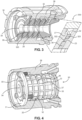
- Figure 3 shows a cross-sectional view of an exemplary neutrode stack 30 in a neutrode housing 38, which includes a plurality of the optimized neutrodes 20 depicted in Fig. 2 , which are coaxially stacked together
- Fig. 4 shows an alternative view of Fig. 3 , in which the outer peripheries 26 of components within a cross-sectional view of neutrode stack housing 38, including the outer peripheries of the stacked optimized neutrodes 20, are shown.
- neutrodes 20 depicted in Fig. 2 can be located in, e.g., the second, third and fourth positions.
- neutrode housing 38 can be made of, e.g., plastic, to likewise maintain the isolation between adjacent neutrodes 20 in neutrode stack 30.
- neutrodes 20 are concentrically aligned along central plasma bores 24 to form neutrode stack 30.
- each neutrode 20 of neutrode stack 30 can have the same number of cooling channels and be oriented so that cooling channels 22 are axially aligned, as depicted in Fig. 4 .
- an insulator 36 can be arranged between adjacent neutrodes 20 as a separator. Insulator 36 can be, e.g., boron nitrite, and can be located radially inside ridge 23 and extend radially inwardly to central plasma bore 34 of neutrode stack 30.
- transitions between central plasma bores 24 of individual neutrodes 20 and insulator 36 within central plasma bore 34 of neutrode 30 can be smooth.
- insulator 36 is suitably thick to maintain an air or gas gap 322 of, e.g., about 0.030" (0.76 mm) between facing surfaces of ridge 23 of a first neutrode 20 and ridge 27 of an adjacent neutrode 20.
- a seal 320 such as an O-ring, which can be made of, e.g., silicon, synthetic rubber such as, e.g., VITON ® , nitrile rubber such as BUNA-N, or other suitable water sealing material suited to withstand the temperatures generated within the region of neutrode stack 30, can be arranged between the facing surfaces of adjacent neutrodes 20 in order to cover air or gas gap 322 and, thereby prevent cooling water ingress from the cooling channels radially inwardly into air or gas gap 322.
- neutrode stack 30 may be sandwiched between a larger diameter disk 31 having cooling water holes 35 and an end piece 33 having cooling channels 37, which can be terminated or blind cooling channels.
- disk 31 includes a number of cooling water holes 35, which corresponds to the number of cooling channels 22 in each neutrode 20 and to the number of cooling channels 37 in end piece 33.
- cooling water holes 35, cooling channels 22 and cooling channels 37 can be oriented so as to be axially aligned, as depicted in Fig. 4 .
- circumferential cooling channels 32 are formed in neutrode stack 30.
- the larger diameter of disk 31 can used, not only for coupling disk 31 to housing 38, e.g., via screws, bolts, clamps, etc., but also to bias disk 31, stacked optimized neutrodes 20 and end piece 33 together.
- the biasing is sufficient so that seals 320 suitably engage the facing surfaces of adjacent neutrodes to achieve the desired water sealing.
- neutrode stack 30 can include more or even fewer of the optimized neutrodes depicted in Fig. 2 .
- neutrode stack housing 38 can include similar cooling channels formed in or on the outer periphery of the housing.
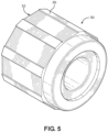
- FIG. 5 shows another exemplary embodiment of a neutrode 50.
- neutrode 50 can include eight (8) flattened cooling channels 52 formed in and around the outer periphery 56 of neutrode 50.
- flattened channels 52 formed in periphery 56 of neutrode 50 can be 0.200" (5.08 mm) wide by 0.0225" (0.572 mm) deep, which provides a total area of 0.032 square inches (20.65 mm 2 ).
- the average water velocity through the channels is 6.4 m/sec.
- these values for the channel are merely exemplary and the number and size of the cooling channels depends upon the water flow needed to prevent temperatures from reaching levels that could damage the gun.
- a neutrode stack can be provided with water cooling channels arranged at an outer perimeter of each optimized neutrode, as shown, e.g., in Figs. 2A , 5 .
- the cross sectional areas of the channels can be designed to create high water velocities, e.g., greater than 1.0 m/sec, preferably greater than 2.0 m/sec, and most preferably greater than 3.0 m/sec, but of less than 8.0 m/sec.
- Each channel can be structured with shapes ranging from a roughly square shape, see, e.g., Fig. 2A - 2E , to an elongated and flattened shape, see, e.g., Fig.
- the channels can also be structured as a triangular arranged to maximize the water cooling flow at the outer periphery of each neutrode.
- the number and size and geometry of the cooling channels are dependent upon the required water flow to prevent temperatures from reaching levels that could damage the gun.
- the total number of neutrodes in the neutrode stack or thickness of each neutrode of the neutrode stack is not limited in this design. In fact, with the optimized neutrodes according to embodiments, longer neutrode stacks are now possible with limited thermal cooling losses.
- the embodiments are not limited to the above-described specific examples of base to depth ratios for the cooling channels. It is understood that the ratio of base to depth for the cooling channels can be up to 1:1 to achieve cooling channels ranging from taller radial profiles to a generally square cross-section, greater than 8:1 to achieve a flatter profile cross-sections, and any ratio within the range between 1:1 and 8:1. Thus, the ratio can be, but again is not limited to, specific ratios of base to depth of 2:1, 3:1, 4:1, 5:1, 6:1, 7:1, and any ratios therebetween.
- a plasma gun comprising a neutrode stack formed by a plurality of neutrodes 50
- water flow in a plasma gun as computed via known computational fluid dynamics (CFD) software, reveals that with a 8.1 liters per minute water flow, the average water velocity in the neutrode stack was above 3.2 m/sec.
- CFD computational fluid dynamics
- a single arc cascaded plasma gun built with neutrode stack 30, as depicted in Fig. 3 was tested and compared to a conventional plasma gun of the same overall design, which included a long nozzle that used water cooling fins or channels to cool the plasma nozzle.
- the test results showed a 10% increase in thermal efficiency with the gun using neutrode stack 30 according to the embodiments of the invention over the conventionally cooled nozzle.
- Other testing showed that adding conventional neutrode stacks to plasma guns reduced thermal efficiency from between 6% and 10%.
Landscapes
- Physics & Mathematics (AREA)
- Engineering & Computer Science (AREA)
- Plasma & Fusion (AREA)
- Spectroscopy & Molecular Physics (AREA)
- Geometry (AREA)
- Plasma Technology (AREA)
- Coating By Spraying Or Casting (AREA)
- Physical Vapour Deposition (AREA)
- Discharge Heating (AREA)
Description
- Embodiments are directed to cascade type plasma guns, and more particularly to optimized neutrodes utilized in such cascade type plasma guns.
- Cascade type plasma guns provide advantages of allowing higher voltages and more stable plasma arcs resulting in more stable gun power. The drawback of such guns is the heat rejection resulting from the plasma arc traveling down a relatively long neutrode stack results in higher thermal losses and limits the practical length of the neutrode stack. Longer stacks result in higher thermal losses offsetting the advantages of higher voltages and more stable arcs. What is needed is a structure that optimizes the cooling in order to limit thermal losses without resulting in thermal damage to the neutrode stack.
- Current neutrode stacks utilize drilled holes concentrically placed as close as practical to the plasma bore so as to remove heat that would result in damage to the neutrodes, the insulators, or the sealing O-rings. Plasma temperatures inside the plasma bore often exceed 20,000K so cooling of the stack is an essential requirement to prevent damage to the components.
- Existing cooling designs for conventional plasma gun nozzles, water cooling channels and/or holes, are typically placed as close to the plasma gun bore as possible to keep temperature of the bore materials as low as possible to prevent damage. This design was carried into the designs for neutrodes as an effective way of cooling.
- Recent inventive discoveries covering thermally optimized plasma gun nozzles, e.g., International Application No.
PCT/US2013/076603 , it was discovered that the nozzle cooling could be altered by moving the water passages away from the plasma gun bore and allow the copper material to move the heat reducing peak temperatures while increasing average temperatures. The water cooling cross section could be reduced to increase water velocity to provide effective cooling sufficient to maintain reasonable temperatures for the plasma gun nozzle while allowing for the increase in average temperature along the bore of the plasma nozzle. Other examples of stacked plasma guns are disclosed inWO 2018/035619 A1 andEP 0 289 961 A . - Embodiments of the invention are directed to a structure and method to optimize the cooling of a neutrode stack in order to reduce maximum or peak stack temperatures while reducing the heat losses to the cooling water at the same time.
- A design and implementation of a thermally optimized neutrode stack for cascaded plasma guns is provided that reduces the thermal loss to the water while minimizing peak stack temperatures. Optimizing the cooling will permit longer neutrode stacks to be used without the penalty of high thermal losses.
- In this regard, the inventors discovered that the technique of moving the water passages away from the plasma gun bore, which allows the copper material of the neutrode to move the heat reducing peak temperatures while increasing average temperatures, could be used on a cascade plasma gun neutrode stack to improve the cooling characteristics without adverse effect on gun behavior.
- Therefore, according to the invention, a neutrode according to claim 1, a plasma gun according to claim 4, and a method for forming a neutrode for a plasma gun according to
claim 12 is provided. Further embodiments of the invention are disclosed in the dependent claims. - In further embodiments, the method can include forming a plurality of water cooling channels at least one of in or on an outer peripheral surface of at least one additional disk-shaped body with an inner bore and coaxially aligning the disk-shaped body and the at least one additional disk-shaped body along the inner bores.
- In embodiments, the method can also include electrically isolating the disk-shaped body from an adjacent one of the at least one additional disk-shaped body. In other embodiments, the disk-shaped body can be separated from the adjacent one of the at least one additional disk-shaped body by at least one of an insulating layer; a gas gap; and a sealing element. In embodiments, each of the disk-shaped body and the at least one additional disk-shaped body may have a same number of water cooling channels, and the method can further include axially aligning the water cooling channels of the coaxially aligned disk-shaped body and at least one additional disk-shaped body. In still further embodiments, the method can include clamping the coaxially aligned disk-shaped body and at least one additional disk-shaped body together as a stacked neutrode for the plasma gun.
- A cascade-type plasma gun with a plurality of the neutrodes, as set forth above, can be formed including aligning the plurality of the neutrodes into a neutrode stack, wherein adjacent neutrodes in the neutrode stack are electrically isolated from each other; and placing the neutrode stack in the cascade-type plasma gun under a clamping force in an axial direction of the neutrode stack.
- The present invention is further described in the detailed description which follows, in reference to the noted plurality of drawings by way of non-limiting examples of exemplary embodiments of the present invention, in which like reference numerals represent similar parts throughout the several views of the drawings, and wherein:
-
Fig. 1 illustrates a conventional neutrode of a known cascaded plasma gun; -
Figs. 2A - 2E illustrate various views of an exemplary optimized neutrode in accordance with embodiments of the invention; -
Fig. 3 illustrates a cross-sectional view of an embodiment of a neutrode stack, which includes a number of the optimized neutrodes depicted inFig. 2 ; -
Fig. 4 illustrates the embodiment depicted inFig. 3 , in which the outer peripheries of the stacked optimized neutrodes are illustrated; and -
Fig. 5 illustrates another embodiment of an optimized neutrode in accordance with embodiments of the invention. - The particulars shown herein are by way of example and for purposes of illustrative discussion of the embodiments of the present invention only and are presented in the cause of providing what is believed to be the most useful and readily understood description of the principles and conceptual aspects of the present invention. In this regard, no attempt is made to show structural details of the present invention in more detail than is necessary for the fundamental understanding of the present invention, the description taken with the drawings making apparent to those skilled in the art how the several forms of the present invention may be embodied in practice.
- To further enhance the cooling optimization, a neutrode stack housing may also contain cooling channels for the return water path arranged in the same fashion as the cooling channels in the neutrodes.
-
Figure 1 shows a cross sectional view of aconventional neutrode 10 from an existing cascaded plasma gun. It is apparent that the cooling in the conventional neutrode is provided by twenty four (24)holes 12 arranged around the central plasma bore 14 in proximity to the bore. - In contrast to the
conventional neutrode 10,Figs. 2A - 2E show various views of an exemplary embodiment of aneutrode 20 with twelve (12) generally square shapedcooling channels 22 formed in and around theouter periphery 26 ofneutrode 20 to surround acentral plasma bore 24.Cooling channels 22 are defined betweenprotrusions 21 radially extending toouter periphery 26. On a first side ofneutrode 20, e.g., right-hand side shown perspectively inFig 2A and shown in plan view inFig. 2C , aridge 23 axially extends from arecessed surface 25 located below the right-hand side ofprotrusions 21. On a second side ofneutrode 20, e.g., left-hand side shown perspectively inFig 2B and shown in plan view inFig. 2D , aridge 27 axially extends from asurface 29, which can be coplanar with the left-hand side ofprotrusions 21.Fig. 2E depicts a side view ofneutrode 20 in which the axial extensions ofridges protrusions 21. - By way of non-limiting example, the
channels 22 defined betweenprotrusions 21 and formed in theperiphery 26 ofneutrode 20 can be 0.125" (3.175 mm) wide by 0.097" (2.464 mm) deep, which provides a total area of 0.1476 square inches (95.22 mm2). When operated at a water flow of twenty two (22) liters per minute, the average water velocity through the channels can be 3.8 m/sec. However, as noted above, these values for the channel are merely exemplary and the number and size of thecooling channels 22 formed betweenprotrusions 21 and in or onperiphery 26 ofneutrode 20 depends upon the water flow needed to prevent temperatures from reaching levels that could damage the gun. -
Figure 3 shows a cross-sectional view of anexemplary neutrode stack 30 in aneutrode housing 38, which includes a plurality of theoptimized neutrodes 20 depicted inFig. 2 , which are coaxially stacked together, andFig. 4 shows an alternative view ofFig. 3 , in which theouter peripheries 26 of components within a cross-sectional view ofneutrode stack housing 38, including the outer peripheries of the stacked optimizedneutrodes 20, are shown. In the illustrated embodiments, when viewed from the left-hand side ofneutrode stack 30,neutrodes 20 depicted inFig. 2 , can be located in, e.g., the second, third and fourth positions. However, theindividual neutrodes 20 are isolated from each other, e.g., electrically isolated and physically spaced, so thatadjacent neutrodes 20 do not contact each other inneutrode stack 30. Further,neutrode housing 38 can be made of, e.g., plastic, to likewise maintain the isolation betweenadjacent neutrodes 20 inneutrode stack 30. - As shown in
Fig. 3 ,neutrodes 20 are concentrically aligned alongcentral plasma bores 24 to formneutrode stack 30. In an advantageous and non-limiting embodiment, eachneutrode 20 ofneutrode stack 30 can have the same number of cooling channels and be oriented so thatcooling channels 22 are axially aligned, as depicted inFig. 4 . Asneutrodes 20 are isolated from each other inneutrode stack 30, aninsulator 36 can be arranged betweenadjacent neutrodes 20 as a separator.Insulator 36 can be, e.g., boron nitrite, and can be located radially insideridge 23 and extend radially inwardly tocentral plasma bore 34 ofneutrode stack 30. In embodiments, transitions between central plasma bores 24 ofindividual neutrodes 20 andinsulator 36 within central plasma bore 34 ofneutrode 30 can be smooth. As more particularly shown in theinset 300,insulator 36 is suitably thick to maintain an air orgas gap 322 of, e.g., about 0.030" (0.76 mm) between facing surfaces ofridge 23 of afirst neutrode 20 andridge 27 of anadjacent neutrode 20. Further, radially outside ofridge 23, aseal 320, such as an O-ring, which can be made of, e.g., silicon, synthetic rubber such as, e.g., VITON®, nitrile rubber such as BUNA-N, or other suitable water sealing material suited to withstand the temperatures generated within the region ofneutrode stack 30, can be arranged between the facing surfaces ofadjacent neutrodes 20 in order to cover air orgas gap 322 and, thereby prevent cooling water ingress from the cooling channels radially inwardly into air orgas gap 322. - In the illustrated embodiments,
neutrode stack 30 may be sandwiched between alarger diameter disk 31 havingcooling water holes 35 and anend piece 33 havingcooling channels 37, which can be terminated or blind cooling channels. In advantageous and non-limiting embodiments,disk 31 includes a number ofcooling water holes 35, which corresponds to the number ofcooling channels 22 in eachneutrode 20 and to the number ofcooling channels 37 inend piece 33. Further, coolingwater holes 35, coolingchannels 22 andcooling channels 37 can be oriented so as to be axially aligned, as depicted inFig. 4 . Still further, as the radially extending portions ofneutrodes 20 that includeperipheral surface 26 are separated from each other in the axial direction,circumferential cooling channels 32 are formed inneutrode stack 30. Moreover, the larger diameter ofdisk 31 can used, not only forcoupling disk 31 tohousing 38, e.g., via screws, bolts, clamps, etc., but also tobias disk 31, stacked optimizedneutrodes 20 andend piece 33 together. Advantageously, the biasing is sufficient so thatseals 320 suitably engage the facing surfaces of adjacent neutrodes to achieve the desired water sealing. In embodiments, it is readily understood thatneutrode stack 30 can include more or even fewer of the optimized neutrodes depicted inFig. 2 . Moreover, it is further understood thatneutrode stack housing 38 can include similar cooling channels formed in or on the outer periphery of the housing. -
Figure 5 shows another exemplary embodiment of aneutrode 50. In this embodiment, neutrode 50 can include eight (8) flattened coolingchannels 52 formed in and around theouter periphery 56 ofneutrode 50. By way of non-limiting example, flattenedchannels 52 formed inperiphery 56 ofneutrode 50 can be 0.200" (5.08 mm) wide by 0.0225" (0.572 mm) deep, which provides a total area of 0.032 square inches (20.65 mm2). When operated at a water flow of 9 liters per minute the average water velocity through the channels is 6.4 m/sec. However, as noted above, these values for the channel are merely exemplary and the number and size of the cooling channels depends upon the water flow needed to prevent temperatures from reaching levels that could damage the gun. - According to embodiments, a neutrode stack can be provided with water cooling channels arranged at an outer perimeter of each optimized neutrode, as shown, e.g., in
Figs. 2A ,5 . The cross sectional areas of the channels can be designed to create high water velocities, e.g., greater than 1.0 m/sec, preferably greater than 2.0 m/sec, and most preferably greater than 3.0 m/sec, but of less than 8.0 m/sec. Each channel can be structured with shapes ranging from a roughly square shape, see, e.g.,Fig. 2A - 2E , to an elongated and flattened shape, see, e.g.,Fig. 5 , in order to maximize the water cooling flow at the outermost periphery of theneutrodes 20. Moreover, the channels can also be structured as a triangular arranged to maximize the water cooling flow at the outer periphery of each neutrode. The number and size and geometry of the cooling channels are dependent upon the required water flow to prevent temperatures from reaching levels that could damage the gun. The total number of neutrodes in the neutrode stack or thickness of each neutrode of the neutrode stack is not limited in this design. In fact, with the optimized neutrodes according to embodiments, longer neutrode stacks are now possible with limited thermal cooling losses. - It is noted that the embodiments are not limited to the above-described specific examples of base to depth ratios for the cooling channels. It is understood that the ratio of base to depth for the cooling channels can be up to 1:1 to achieve cooling channels ranging from taller radial profiles to a generally square cross-section, greater than 8:1 to achieve a flatter profile cross-sections, and any ratio within the range between 1:1 and 8:1. Thus, the ratio can be, but again is not limited to, specific ratios of base to depth of 2:1, 3:1, 4:1, 5:1, 6:1, 7:1, and any ratios therebetween.
- In a plasma gun comprising a neutrode stack formed by a plurality of
neutrodes 50, water flow in a plasma gun, as computed via known computational fluid dynamics (CFD) software, reveals that with a 8.1 liters per minute water flow, the average water velocity in the neutrode stack was above 3.2 m/sec. - A single arc cascaded plasma gun built with
neutrode stack 30, as depicted inFig. 3 , was tested and compared to a conventional plasma gun of the same overall design, which included a long nozzle that used water cooling fins or channels to cool the plasma nozzle. The test results showed a 10% increase in thermal efficiency with the gun usingneutrode stack 30 according to the embodiments of the invention over the conventionally cooled nozzle. Other testing showed that adding conventional neutrode stacks to plasma guns reduced thermal efficiency from between 6% and 10%. Still further testing showed that doubling the length of a conventional neutrode stack for a plasma gun reduced thermal efficiency by 20% while increasing the length ofneutrode stack 30 with added optimizedneutrodes 20 had a much lower decrease in thermal efficiency, which worked out to be about less than one-half that of conventional neutrode stacks. Moreover, duration testing ofneutrode stack 30 showed no adverse thermal effects even after more than 200 hours of testing with the same stack. - It is noted that the foregoing examples have been provided merely for the purpose of explanation and are in no way to be construed as limiting of the present invention. While the present invention has been described with reference to an exemplary embodiment, it is understood that the words which have been used herein are words of description and illustration, rather than words of limitation. Changes may be made, within the purview of the appended claims, as presently stated and as amended, without departing from the scope of the present invention in its aspects as defined by the claims.
Claims (13)
- A neutrode (20) of a plasma gun comprising:a disk-shaped body having an outer peripheral surface (26) and an inner bore (24); anda plurality of axially oriented cooling channels (22) formed at least one of in or on the outerperipheral surface (26), wherein the cooling channels (22) are defined by a depth dimensionbelow the outer peripheral surface and a base dimension normal to the depth dimension, wherein a ratio of base to depth for the cooling channels (22) is 2 : 1 or higher
- The neutrode (20) in accordance with claim 1, wherein the cooling channels (22) have a flattened profile with a width more than eight times greater than a depth.
- The neutrode (20) in accordance with claim 1, wherein the cooling channels (22) are structured to provide an average water velocity through the channels of less than 8.0 m/sec and at least one of:greater than 1.0 m/sec,greater than 2.0 m/sec, andgreater than 3.0 m/sec.
- A plasma gun comprising:
a neutrode stack (30) comprising a plurality of the neutrodes (20) in accordance with claim 1 - The plasma gun in accordance with claim 4, wherein adjacent neutrodes (20) in the neutrode stack (30) are electrically isolated from each other.
- The plasma gun in accordance with claim 5, further comprising an insulation layer arranged between the adjacent neutrodes.
- The plasma gun in accordance with claim 5, further comprising a sealing element layer arranged to form a water barrier between the adjacent neutrodes.
- The plasma gun in accordance with claim 5, further comprising a gas gap formed between the adjacent neutrodes.
- The plasma gun in accordance with claim 5, wherein each of the plurality of neutrodes has a same number of cooling channels, and the plurality of neutrodes are arranged so that the cooling channels are axially aligned.
- The plasma gun in accordance with claim 9, further comprising circumferential cooling channels formed between the adjacent neutrodes.
- The plasma gun in accordance with claim 4, wherein the plurality of neutrodes, while physically separated from each other, are clamped together under force.
- A method of forming a neutrode (20) of a plasma gun, comprising:
forming a plurality of axially oriented water-cooling channels (22) at least one of in or on an outer peripheral surface (26) of a disk-shaped body with an inner bore (24), wherein the cooling channels (22) are defined by a depth dimension below the outer peripheral surface (26) and a base dimension normal to the depth dimension, wherein a ratio of base to depth for the cooling channels (22) is 2 : 1 or higher - The method according to claim 12, wherein the plurality of water-cooling channels is structured to provide an average water velocity through the channels of less than 8.0 m/ sec and at least at least one of:greater than 1.0 m/sec,greater than 2.0 m/sec, andgreater than 3.0 m/sec.
Applications Claiming Priority (2)
| Application Number | Priority Date | Filing Date | Title |
|---|---|---|---|
| US201762472202P | 2017-03-16 | 2017-03-16 | |
| PCT/US2018/022373 WO2018170090A1 (en) | 2017-03-16 | 2018-03-14 | Optimized neutrode stack cooling for a plasma gun |
Publications (3)
| Publication Number | Publication Date |
|---|---|
| EP3597017A1 EP3597017A1 (en) | 2020-01-22 |
| EP3597017A4 EP3597017A4 (en) | 2021-01-06 |
| EP3597017B1 true EP3597017B1 (en) | 2023-05-03 |
Family
ID=63523877
Family Applications (1)
| Application Number | Title | Priority Date | Filing Date |
|---|---|---|---|
| EP18768537.5A Active EP3597017B1 (en) | 2017-03-16 | 2018-03-14 | Optimized neutrode stack cooling for a plasma gun |
Country Status (8)
| Country | Link |
|---|---|
| US (1) | US20200163198A1 (en) |
| EP (1) | EP3597017B1 (en) |
| JP (1) | JP7149954B2 (en) |
| CN (1) | CN110870388B (en) |
| CA (1) | CA3057456A1 (en) |
| ES (1) | ES2951690T3 (en) |
| PL (1) | PL3597017T3 (en) |
| WO (1) | WO2018170090A1 (en) |
Families Citing this family (1)
| Publication number | Priority date | Publication date | Assignee | Title |
|---|---|---|---|---|
| RU2020129100A (en) * | 2018-02-20 | 2022-03-21 | ЭРЛИКОН МЕТКО (ЮЭс) ИНК. | SINGLE-ARC CASCADE LOW-PRESSURE PLASMA TORCH USING A NEUTRODE PACKAGE AS A METHOD OF PLASMA ARC CONTROL |
Citations (1)
| Publication number | Priority date | Publication date | Assignee | Title |
|---|---|---|---|---|
| EP0289961A2 (en) * | 1987-05-08 | 1988-11-09 | The Perkin-Elmer Corporation | Arc device with adjustable cathode |
Family Cites Families (22)
| Publication number | Priority date | Publication date | Assignee | Title |
|---|---|---|---|---|
| DE4105407A1 (en) * | 1991-02-21 | 1992-08-27 | Plasma Technik Ag | PLASMA SPRAYER FOR SPRAYING SOLID, POWDER-SHAPED OR GAS-SHAPED MATERIAL |
| FR2735939B1 (en) * | 1995-06-20 | 1997-09-26 | Aerospatiale | EXTERNAL COOLING DEVICE OF A PLASMA TORCH |
| JP4183814B2 (en) * | 1998-12-11 | 2008-11-19 | 株式会社三井三池製作所 | Cage electric motor |
| NL1023491C2 (en) * | 2003-05-21 | 2004-11-24 | Otb Groep B V | Cascade source. |
| US7030336B1 (en) * | 2003-12-11 | 2006-04-18 | Sulzer Metco (Us) Inc. | Method of fixing anodic arc attachments of a multiple arc plasma gun and nozzle device for same |
| CN2719473Y (en) * | 2004-05-18 | 2005-08-24 | 杨迎元 | Plasma welding gun |
| WO2007018575A2 (en) * | 2004-11-12 | 2007-02-15 | Thorrn Micro Technologies, Inc. | Ion generation by the temporal control of gaseous dielectric breakdown |
| US7717703B2 (en) | 2005-02-25 | 2010-05-18 | Technical Engineering, Llc | Combustion head for use with a flame spray apparatus |
| US7759599B2 (en) * | 2005-04-29 | 2010-07-20 | Sulzer Metco (Us), Inc. | Interchangeable plasma nozzle interface |
| CA2676909C (en) * | 2007-02-02 | 2015-12-08 | Plasma Technologies Ltd. | Plasma spraying device and method |
| US7928338B2 (en) | 2007-02-02 | 2011-04-19 | Plasma Surgical Investments Ltd. | Plasma spraying device and method |
| CN101541465B (en) * | 2007-02-09 | 2012-11-14 | 海别得公司 | Plasma arc torch cutting component with optimized water cooling |
| EP2177092B1 (en) * | 2007-08-06 | 2017-09-27 | Plasma Surgical Investments Limited | Pulsed plasma device |
| TWI352368B (en) | 2007-09-21 | 2011-11-11 | Ind Tech Res Inst | Plasma head and plasma-discharging device using th |
| CA2856375A1 (en) * | 2012-02-28 | 2013-09-06 | Sulzer Metco (Us), Inc. | Extended cascade plasma gun |
| JP6469023B2 (en) * | 2013-01-31 | 2019-02-13 | エリコン メテコ(ユーエス)インコーポレイテッド | Optimized thermal nozzle and method of using the same |
| JP6602204B2 (en) | 2013-01-31 | 2019-11-06 | エリコン メテコ(ユーエス)インコーポレイテッド | Long-life nozzle for thermal spray gun and its production and use |
| AU2013408315B2 (en) * | 2013-12-19 | 2019-01-17 | Oerlikon Metco (Us) Inc. | Long-life plasma nozzle with liner |
| US9833859B2 (en) * | 2014-09-15 | 2017-12-05 | Lincoln Global, Inc. | Electric arc torch with cooling conduit |
| US11511298B2 (en) * | 2014-12-12 | 2022-11-29 | Oerlikon Metco (Us) Inc. | Corrosion protection for plasma gun nozzles and method of protecting gun nozzles |
| CN107113957B (en) * | 2015-06-08 | 2021-03-12 | 海别得公司 | Cooling plasma torch nozzles and related systems and methods |
| CH712835A1 (en) * | 2016-08-26 | 2018-02-28 | Amt Ag | Plasma injector. |
-
2018
- 2018-03-14 JP JP2019550629A patent/JP7149954B2/en active Active
- 2018-03-14 US US16/493,479 patent/US20200163198A1/en active Pending
- 2018-03-14 CN CN201880032507.1A patent/CN110870388B/en active Active
- 2018-03-14 WO PCT/US2018/022373 patent/WO2018170090A1/en not_active Ceased
- 2018-03-14 PL PL18768537.5T patent/PL3597017T3/en unknown
- 2018-03-14 EP EP18768537.5A patent/EP3597017B1/en active Active
- 2018-03-14 CA CA3057456A patent/CA3057456A1/en active Pending
- 2018-03-14 ES ES18768537T patent/ES2951690T3/en active Active
Patent Citations (1)
| Publication number | Priority date | Publication date | Assignee | Title |
|---|---|---|---|---|
| EP0289961A2 (en) * | 1987-05-08 | 1988-11-09 | The Perkin-Elmer Corporation | Arc device with adjustable cathode |
Also Published As
| Publication number | Publication date |
|---|---|
| CA3057456A1 (en) | 2018-09-20 |
| WO2018170090A1 (en) | 2018-09-20 |
| CN110870388A (en) | 2020-03-06 |
| ES2951690T3 (en) | 2023-10-24 |
| US20200163198A1 (en) | 2020-05-21 |
| EP3597017A4 (en) | 2021-01-06 |
| JP7149954B2 (en) | 2022-10-07 |
| CN110870388B (en) | 2023-03-31 |
| EP3597017A1 (en) | 2020-01-22 |
| JP2020511750A (en) | 2020-04-16 |
| PL3597017T3 (en) | 2023-09-18 |
Similar Documents
| Publication | Publication Date | Title |
|---|---|---|
| EP2058926B1 (en) | Enhanced motor cooling system | |
| EP2369723B1 (en) | Cooling arrangement for an electric machine | |
| US6661133B2 (en) | Rotor cooling arrangement | |
| EP1557929B1 (en) | Method and apparatus for reducing hot spot temperatures on stacked field windings | |
| US9608550B2 (en) | Lightup prevention using multi-layer ceramic fabrication techniques | |
| ITTO20090317A1 (en) | COOLING SYSTEM FOR HIGH VOLTAGE POWER DENSITY ELECTRIC MOTOR, IN PARTICULAR ELECTRIC AXIAL FLOW MOTOR | |
| US20120098362A1 (en) | Dynamoelectric machine coil spacerblock having flow deflecting channel in coil facing surface thereof | |
| WO2022267452A1 (en) | Stator frame, magnetic bearing, compressor, and air conditioner | |
| EP2069664B1 (en) | Improvements in fluid control | |
| US20200163198A1 (en) | Optimized neutrode stack cooling for a plasma gun | |
| CA2399343C (en) | Spaceblock scoops for enhanced rotor cavity heat transfer | |
| CN114337015A (en) | High power density motor with stator immersion oil cooling structure | |
| CA2590628A1 (en) | Flame arrester arrangement and method of incorporating bores in a flame arrester arrangement | |
| US20100001213A1 (en) | Fluid Control | |
| CN110360223B (en) | An air bearing | |
| EP3756423B1 (en) | Single arc cascaded low pressure coating gun utilizing a neutrode stack as a method of plasma arc control | |
| US8525376B2 (en) | Dynamoelectric machine coil spaceblock having flow deflecting structure in coil facing surface thereof | |
| CN108964315A (en) | rotor, motor and compressor | |
| US7342345B2 (en) | Paddled rotor spaceblocks | |
| JP5612408B2 (en) | Positioning pin and semiconductor manufacturing apparatus adaptable to deformation caused by difference in thermal expansion coefficient | |
| US4794304A (en) | Magnetron with cooling fin structure | |
| KR102700455B1 (en) | The manufacturing method of cooling assembly for elctric motor housing | |
| RU2006138C1 (en) | Cooling wedge of nonsalient-pole rotor |
Legal Events
| Date | Code | Title | Description |
|---|---|---|---|
| STAA | Information on the status of an ep patent application or granted ep patent |
Free format text: STATUS: THE INTERNATIONAL PUBLICATION HAS BEEN MADE |
|
| PUAI | Public reference made under article 153(3) epc to a published international application that has entered the european phase |
Free format text: ORIGINAL CODE: 0009012 |
|
| STAA | Information on the status of an ep patent application or granted ep patent |
Free format text: STATUS: REQUEST FOR EXAMINATION WAS MADE |
|
| 17P | Request for examination filed |
Effective date: 20191016 |
|
| AK | Designated contracting states |
Kind code of ref document: A1 Designated state(s): AL AT BE BG CH CY CZ DE DK EE ES FI FR GB GR HR HU IE IS IT LI LT LU LV MC MK MT NL NO PL PT RO RS SE SI SK SM TR |
|
| AX | Request for extension of the european patent |
Extension state: BA ME |
|
| DAV | Request for validation of the european patent (deleted) | ||
| DAX | Request for extension of the european patent (deleted) | ||
| A4 | Supplementary search report drawn up and despatched |
Effective date: 20201207 |
|
| RIC1 | Information provided on ipc code assigned before grant |
Ipc: H05H 1/32 20060101ALI20201201BHEP Ipc: H05H 1/34 20060101AFI20201201BHEP Ipc: H05H 1/24 20060101ALI20201201BHEP Ipc: H05H 1/26 20060101ALI20201201BHEP Ipc: H05H 1/28 20060101ALI20201201BHEP |
|
| GRAP | Despatch of communication of intention to grant a patent |
Free format text: ORIGINAL CODE: EPIDOSNIGR1 |
|
| STAA | Information on the status of an ep patent application or granted ep patent |
Free format text: STATUS: GRANT OF PATENT IS INTENDED |
|
| INTG | Intention to grant announced |
Effective date: 20221124 |
|
| GRAS | Grant fee paid |
Free format text: ORIGINAL CODE: EPIDOSNIGR3 |
|
| GRAA | (expected) grant |
Free format text: ORIGINAL CODE: 0009210 |
|
| STAA | Information on the status of an ep patent application or granted ep patent |
Free format text: STATUS: THE PATENT HAS BEEN GRANTED |
|
| AK | Designated contracting states |
Kind code of ref document: B1 Designated state(s): AL AT BE BG CH CY CZ DE DK EE ES FI FR GB GR HR HU IE IS IT LI LT LU LV MC MK MT NL NO PL PT RO RS SE SI SK SM TR |
|
| REG | Reference to a national code |
Ref country code: GB Ref legal event code: FG4D |
|
| REG | Reference to a national code |
Ref country code: DE Ref legal event code: R096 Ref document number: 602018049256 Country of ref document: DE |
|
| REG | Reference to a national code |
Ref country code: AT Ref legal event code: REF Ref document number: 1565782 Country of ref document: AT Kind code of ref document: T Effective date: 20230515 Ref country code: CH Ref legal event code: EP |
|
| REG | Reference to a national code |
Ref country code: IE Ref legal event code: FG4D |
|
| REG | Reference to a national code |
Ref country code: NL Ref legal event code: FP |
|
| REG | Reference to a national code |
Ref country code: SE Ref legal event code: TRGR |
|
| REG | Reference to a national code |
Ref country code: LT Ref legal event code: MG9D |
|
| REG | Reference to a national code |
Ref country code: AT Ref legal event code: MK05 Ref document number: 1565782 Country of ref document: AT Kind code of ref document: T Effective date: 20230503 |
|
| REG | Reference to a national code |
Ref country code: ES Ref legal event code: FG2A Ref document number: 2951690 Country of ref document: ES Kind code of ref document: T3 Effective date: 20231024 |
|
| PG25 | Lapsed in a contracting state [announced via postgrant information from national office to epo] |
Ref country code: PT Free format text: LAPSE BECAUSE OF FAILURE TO SUBMIT A TRANSLATION OF THE DESCRIPTION OR TO PAY THE FEE WITHIN THE PRESCRIBED TIME-LIMIT Effective date: 20230904 Ref country code: NO Free format text: LAPSE BECAUSE OF FAILURE TO SUBMIT A TRANSLATION OF THE DESCRIPTION OR TO PAY THE FEE WITHIN THE PRESCRIBED TIME-LIMIT Effective date: 20230803 Ref country code: AT Free format text: LAPSE BECAUSE OF FAILURE TO SUBMIT A TRANSLATION OF THE DESCRIPTION OR TO PAY THE FEE WITHIN THE PRESCRIBED TIME-LIMIT Effective date: 20230503 |
|
| PG25 | Lapsed in a contracting state [announced via postgrant information from national office to epo] |
Ref country code: RS Free format text: LAPSE BECAUSE OF FAILURE TO SUBMIT A TRANSLATION OF THE DESCRIPTION OR TO PAY THE FEE WITHIN THE PRESCRIBED TIME-LIMIT Effective date: 20230503 Ref country code: LV Free format text: LAPSE BECAUSE OF FAILURE TO SUBMIT A TRANSLATION OF THE DESCRIPTION OR TO PAY THE FEE WITHIN THE PRESCRIBED TIME-LIMIT Effective date: 20230503 Ref country code: LT Free format text: LAPSE BECAUSE OF FAILURE TO SUBMIT A TRANSLATION OF THE DESCRIPTION OR TO PAY THE FEE WITHIN THE PRESCRIBED TIME-LIMIT Effective date: 20230503 Ref country code: IS Free format text: LAPSE BECAUSE OF FAILURE TO SUBMIT A TRANSLATION OF THE DESCRIPTION OR TO PAY THE FEE WITHIN THE PRESCRIBED TIME-LIMIT Effective date: 20230903 Ref country code: HR Free format text: LAPSE BECAUSE OF FAILURE TO SUBMIT A TRANSLATION OF THE DESCRIPTION OR TO PAY THE FEE WITHIN THE PRESCRIBED TIME-LIMIT Effective date: 20230503 Ref country code: GR Free format text: LAPSE BECAUSE OF FAILURE TO SUBMIT A TRANSLATION OF THE DESCRIPTION OR TO PAY THE FEE WITHIN THE PRESCRIBED TIME-LIMIT Effective date: 20230804 |
|
| PG25 | Lapsed in a contracting state [announced via postgrant information from national office to epo] |
Ref country code: FI Free format text: LAPSE BECAUSE OF FAILURE TO SUBMIT A TRANSLATION OF THE DESCRIPTION OR TO PAY THE FEE WITHIN THE PRESCRIBED TIME-LIMIT Effective date: 20230503 |
|
| PG25 | Lapsed in a contracting state [announced via postgrant information from national office to epo] |
Ref country code: SK Free format text: LAPSE BECAUSE OF FAILURE TO SUBMIT A TRANSLATION OF THE DESCRIPTION OR TO PAY THE FEE WITHIN THE PRESCRIBED TIME-LIMIT Effective date: 20230503 |
|
| PG25 | Lapsed in a contracting state [announced via postgrant information from national office to epo] |
Ref country code: SM Free format text: LAPSE BECAUSE OF FAILURE TO SUBMIT A TRANSLATION OF THE DESCRIPTION OR TO PAY THE FEE WITHIN THE PRESCRIBED TIME-LIMIT Effective date: 20230503 Ref country code: SK Free format text: LAPSE BECAUSE OF FAILURE TO SUBMIT A TRANSLATION OF THE DESCRIPTION OR TO PAY THE FEE WITHIN THE PRESCRIBED TIME-LIMIT Effective date: 20230503 Ref country code: RO Free format text: LAPSE BECAUSE OF FAILURE TO SUBMIT A TRANSLATION OF THE DESCRIPTION OR TO PAY THE FEE WITHIN THE PRESCRIBED TIME-LIMIT Effective date: 20230503 Ref country code: EE Free format text: LAPSE BECAUSE OF FAILURE TO SUBMIT A TRANSLATION OF THE DESCRIPTION OR TO PAY THE FEE WITHIN THE PRESCRIBED TIME-LIMIT Effective date: 20230503 Ref country code: DK Free format text: LAPSE BECAUSE OF FAILURE TO SUBMIT A TRANSLATION OF THE DESCRIPTION OR TO PAY THE FEE WITHIN THE PRESCRIBED TIME-LIMIT Effective date: 20230503 Ref country code: CZ Free format text: LAPSE BECAUSE OF FAILURE TO SUBMIT A TRANSLATION OF THE DESCRIPTION OR TO PAY THE FEE WITHIN THE PRESCRIBED TIME-LIMIT Effective date: 20230503 |
|
| REG | Reference to a national code |
Ref country code: DE Ref legal event code: R097 Ref document number: 602018049256 Country of ref document: DE |
|
| PLBE | No opposition filed within time limit |
Free format text: ORIGINAL CODE: 0009261 |
|
| STAA | Information on the status of an ep patent application or granted ep patent |
Free format text: STATUS: NO OPPOSITION FILED WITHIN TIME LIMIT |
|
| 26N | No opposition filed |
Effective date: 20240206 |
|
| PG25 | Lapsed in a contracting state [announced via postgrant information from national office to epo] |
Ref country code: SI Free format text: LAPSE BECAUSE OF FAILURE TO SUBMIT A TRANSLATION OF THE DESCRIPTION OR TO PAY THE FEE WITHIN THE PRESCRIBED TIME-LIMIT Effective date: 20230503 |
|
| PG25 | Lapsed in a contracting state [announced via postgrant information from national office to epo] |
Ref country code: SI Free format text: LAPSE BECAUSE OF FAILURE TO SUBMIT A TRANSLATION OF THE DESCRIPTION OR TO PAY THE FEE WITHIN THE PRESCRIBED TIME-LIMIT Effective date: 20230503 |
|
| PG25 | Lapsed in a contracting state [announced via postgrant information from national office to epo] |
Ref country code: BG Free format text: LAPSE BECAUSE OF FAILURE TO SUBMIT A TRANSLATION OF THE DESCRIPTION OR TO PAY THE FEE WITHIN THE PRESCRIBED TIME-LIMIT Effective date: 20230503 |
|
| PG25 | Lapsed in a contracting state [announced via postgrant information from national office to epo] |
Ref country code: LU Free format text: LAPSE BECAUSE OF NON-PAYMENT OF DUE FEES Effective date: 20240314 |
|
| PG25 | Lapsed in a contracting state [announced via postgrant information from national office to epo] |
Ref country code: MC Free format text: LAPSE BECAUSE OF FAILURE TO SUBMIT A TRANSLATION OF THE DESCRIPTION OR TO PAY THE FEE WITHIN THE PRESCRIBED TIME-LIMIT Effective date: 20230503 |
|
| PG25 | Lapsed in a contracting state [announced via postgrant information from national office to epo] |
Ref country code: MC Free format text: LAPSE BECAUSE OF FAILURE TO SUBMIT A TRANSLATION OF THE DESCRIPTION OR TO PAY THE FEE WITHIN THE PRESCRIBED TIME-LIMIT Effective date: 20230503 Ref country code: LU Free format text: LAPSE BECAUSE OF NON-PAYMENT OF DUE FEES Effective date: 20240314 Ref country code: BG Free format text: LAPSE BECAUSE OF FAILURE TO SUBMIT A TRANSLATION OF THE DESCRIPTION OR TO PAY THE FEE WITHIN THE PRESCRIBED TIME-LIMIT Effective date: 20230503 |
|
| PG25 | Lapsed in a contracting state [announced via postgrant information from national office to epo] |
Ref country code: IE Free format text: LAPSE BECAUSE OF NON-PAYMENT OF DUE FEES Effective date: 20240314 |
|
| PG25 | Lapsed in a contracting state [announced via postgrant information from national office to epo] |
Ref country code: IE Free format text: LAPSE BECAUSE OF NON-PAYMENT OF DUE FEES Effective date: 20240314 |
|
| PGFP | Annual fee paid to national office [announced via postgrant information from national office to epo] |
Ref country code: ES Payment date: 20250423 Year of fee payment: 8 |
|
| PGFP | Annual fee paid to national office [announced via postgrant information from national office to epo] |
Ref country code: CH Payment date: 20250401 Year of fee payment: 8 |
|
| PG25 | Lapsed in a contracting state [announced via postgrant information from national office to epo] |
Ref country code: CY Free format text: LAPSE BECAUSE OF FAILURE TO SUBMIT A TRANSLATION OF THE DESCRIPTION OR TO PAY THE FEE WITHIN THE PRESCRIBED TIME-LIMIT; INVALID AB INITIO Effective date: 20180314 |
|
| PG25 | Lapsed in a contracting state [announced via postgrant information from national office to epo] |
Ref country code: HU Free format text: LAPSE BECAUSE OF FAILURE TO SUBMIT A TRANSLATION OF THE DESCRIPTION OR TO PAY THE FEE WITHIN THE PRESCRIBED TIME-LIMIT; INVALID AB INITIO Effective date: 20180314 |
|
| PG25 | Lapsed in a contracting state [announced via postgrant information from national office to epo] |
Ref country code: TR Free format text: LAPSE BECAUSE OF FAILURE TO SUBMIT A TRANSLATION OF THE DESCRIPTION OR TO PAY THE FEE WITHIN THE PRESCRIBED TIME-LIMIT Effective date: 20230503 |
|
| REG | Reference to a national code |
Ref country code: CH Ref legal event code: U11 Free format text: ST27 STATUS EVENT CODE: U-0-0-U10-U11 (AS PROVIDED BY THE NATIONAL OFFICE) Effective date: 20260401 |
|
| PGFP | Annual fee paid to national office [announced via postgrant information from national office to epo] |
Ref country code: SE Payment date: 20260323 Year of fee payment: 9 |
|
| PGFP | Annual fee paid to national office [announced via postgrant information from national office to epo] |
Ref country code: GB Payment date: 20260319 Year of fee payment: 9 |
|
| PGFP | Annual fee paid to national office [announced via postgrant information from national office to epo] |
Ref country code: DE Payment date: 20260320 Year of fee payment: 9 |
|
| PGFP | Annual fee paid to national office [announced via postgrant information from national office to epo] |
Ref country code: BE Payment date: 20260323 Year of fee payment: 9 Ref country code: IT Payment date: 20260320 Year of fee payment: 9 |
|
| PGFP | Annual fee paid to national office [announced via postgrant information from national office to epo] |
Ref country code: NL Payment date: 20260323 Year of fee payment: 9 |
|
| PGFP | Annual fee paid to national office [announced via postgrant information from national office to epo] |
Ref country code: FR Payment date: 20260323 Year of fee payment: 9 |
|
| PGFP | Annual fee paid to national office [announced via postgrant information from national office to epo] |
Ref country code: PL Payment date: 20260223 Year of fee payment: 9 |