EP3596569B1 - System and method for integrating flight path and site operating data - Google Patents
System and method for integrating flight path and site operating data Download PDFInfo
- Publication number
- EP3596569B1 EP3596569B1 EP18766897.5A EP18766897A EP3596569B1 EP 3596569 B1 EP3596569 B1 EP 3596569B1 EP 18766897 A EP18766897 A EP 18766897A EP 3596569 B1 EP3596569 B1 EP 3596569B1
- Authority
- EP
- European Patent Office
- Prior art keywords
- asset
- inspection
- flight plan
- data
- controller
- Prior art date
- Legal status (The legal status is an assumption and is not a legal conclusion. Google has not performed a legal analysis and makes no representation as to the accuracy of the status listed.)
- Active
Links
Images


Classifications
-
- G—PHYSICS
- G05—CONTROLLING; REGULATING
- G05B—CONTROL OR REGULATING SYSTEMS IN GENERAL; FUNCTIONAL ELEMENTS OF SUCH SYSTEMS; MONITORING OR TESTING ARRANGEMENTS FOR SUCH SYSTEMS OR ELEMENTS
- G05B23/00—Testing or monitoring of control systems or parts thereof
- G05B23/02—Electric testing or monitoring
-
- G—PHYSICS
- G05—CONTROLLING; REGULATING
- G05D—SYSTEMS FOR CONTROLLING OR REGULATING NON-ELECTRIC VARIABLES
- G05D1/00—Control of position, course, altitude or attitude of land, water, air or space vehicles, e.g. using automatic pilots
- G05D1/0094—Control of position, course, altitude or attitude of land, water, air or space vehicles, e.g. using automatic pilots involving pointing a payload, e.g. camera, weapon, sensor, towards a fixed or moving target
-
- B—PERFORMING OPERATIONS; TRANSPORTING
- B64—AIRCRAFT; AVIATION; COSMONAUTICS
- B64C—AEROPLANES; HELICOPTERS
- B64C39/00—Aircraft not otherwise provided for
- B64C39/02—Aircraft not otherwise provided for characterised by special use
- B64C39/024—Aircraft not otherwise provided for characterised by special use of the remote controlled vehicle type, i.e. RPV
-
- F—MECHANICAL ENGINEERING; LIGHTING; HEATING; WEAPONS; BLASTING
- F03—MACHINES OR ENGINES FOR LIQUIDS; WIND, SPRING, OR WEIGHT MOTORS; PRODUCING MECHANICAL POWER OR A REACTIVE PROPULSIVE THRUST, NOT OTHERWISE PROVIDED FOR
- F03D—WIND MOTORS
- F03D17/00—Monitoring or testing of wind motors, e.g. diagnostics
-
- G—PHYSICS
- G05—CONTROLLING; REGULATING
- G05D—SYSTEMS FOR CONTROLLING OR REGULATING NON-ELECTRIC VARIABLES
- G05D1/00—Control of position, course, altitude or attitude of land, water, air or space vehicles, e.g. using automatic pilots
- G05D1/0011—Control of position, course, altitude or attitude of land, water, air or space vehicles, e.g. using automatic pilots associated with a remote control arrangement
-
- G—PHYSICS
- G05—CONTROLLING; REGULATING
- G05D—SYSTEMS FOR CONTROLLING OR REGULATING NON-ELECTRIC VARIABLES
- G05D1/00—Control of position, course, altitude or attitude of land, water, air or space vehicles, e.g. using automatic pilots
- G05D1/40—Control within particular dimensions
- G05D1/46—Control of position or course in three dimensions [3D]
-
- G—PHYSICS
- G05—CONTROLLING; REGULATING
- G05D—SYSTEMS FOR CONTROLLING OR REGULATING NON-ELECTRIC VARIABLES
- G05D1/00—Control of position, course, altitude or attitude of land, water, air or space vehicles, e.g. using automatic pilots
- G05D1/60—Intended control result
- G05D1/69—Coordinated control of the position or course of two or more vehicles
-
- G—PHYSICS
- G06—COMPUTING OR CALCULATING; COUNTING
- G06Q—INFORMATION AND COMMUNICATION TECHNOLOGY [ICT] SPECIALLY ADAPTED FOR ADMINISTRATIVE, COMMERCIAL, FINANCIAL, MANAGERIAL OR SUPERVISORY PURPOSES; SYSTEMS OR METHODS SPECIALLY ADAPTED FOR ADMINISTRATIVE, COMMERCIAL, FINANCIAL, MANAGERIAL OR SUPERVISORY PURPOSES, NOT OTHERWISE PROVIDED FOR
- G06Q10/00—Administration; Management
- G06Q10/06—Resources, workflows, human or project management; Enterprise or organisation planning; Enterprise or organisation modelling
-
- G—PHYSICS
- G08—SIGNALLING
- G08G—TRAFFIC CONTROL SYSTEMS
- G08G5/00—Traffic control systems for aircraft
- G08G5/20—Arrangements for acquiring, generating, sharing or displaying traffic information
- G08G5/22—Arrangements for acquiring, generating, sharing or displaying traffic information located on the ground
-
- G—PHYSICS
- G08—SIGNALLING
- G08G—TRAFFIC CONTROL SYSTEMS
- G08G5/00—Traffic control systems for aircraft
- G08G5/20—Arrangements for acquiring, generating, sharing or displaying traffic information
- G08G5/26—Transmission of traffic-related information between aircraft and ground stations
-
- G—PHYSICS
- G08—SIGNALLING
- G08G—TRAFFIC CONTROL SYSTEMS
- G08G5/00—Traffic control systems for aircraft
- G08G5/50—Navigation or guidance aids
- G08G5/55—Navigation or guidance aids for a single aircraft
-
- G—PHYSICS
- G08—SIGNALLING
- G08G—TRAFFIC CONTROL SYSTEMS
- G08G5/00—Traffic control systems for aircraft
- G08G5/70—Arrangements for monitoring traffic-related situations or conditions
-
- B—PERFORMING OPERATIONS; TRANSPORTING
- B64—AIRCRAFT; AVIATION; COSMONAUTICS
- B64U—UNMANNED AERIAL VEHICLES [UAV]; EQUIPMENT THEREFOR
- B64U2101/00—UAVs specially adapted for particular uses or applications
- B64U2101/25—UAVs specially adapted for particular uses or applications for manufacturing or servicing
- B64U2101/26—UAVs specially adapted for particular uses or applications for manufacturing or servicing for manufacturing, inspections or repairs
-
- B—PERFORMING OPERATIONS; TRANSPORTING
- B64—AIRCRAFT; AVIATION; COSMONAUTICS
- B64U—UNMANNED AERIAL VEHICLES [UAV]; EQUIPMENT THEREFOR
- B64U2101/00—UAVs specially adapted for particular uses or applications
- B64U2101/30—UAVs specially adapted for particular uses or applications for imaging, photography or videography
-
- B—PERFORMING OPERATIONS; TRANSPORTING
- B64—AIRCRAFT; AVIATION; COSMONAUTICS
- B64U—UNMANNED AERIAL VEHICLES [UAV]; EQUIPMENT THEREFOR
- B64U2201/00—UAVs characterised by their flight controls
- B64U2201/20—Remote controls
-
- G—PHYSICS
- G01—MEASURING; TESTING
- G01C—MEASURING DISTANCES, LEVELS OR BEARINGS; SURVEYING; NAVIGATION; GYROSCOPIC INSTRUMENTS; PHOTOGRAMMETRY OR VIDEOGRAMMETRY
- G01C21/00—Navigation; Navigational instruments not provided for in groups G01C1/00 - G01C19/00
- G01C21/20—Instruments for performing navigational calculations
-
- G—PHYSICS
- G05—CONTROLLING; REGULATING
- G05B—CONTROL OR REGULATING SYSTEMS IN GENERAL; FUNCTIONAL ELEMENTS OF SUCH SYSTEMS; MONITORING OR TESTING ARRANGEMENTS FOR SUCH SYSTEMS OR ELEMENTS
- G05B2219/00—Program-control systems
- G05B2219/20—Pc systems
- G05B2219/24—Pc safety
- G05B2219/24215—Scada supervisory control and data acquisition
-
- G—PHYSICS
- G05—CONTROLLING; REGULATING
- G05D—SYSTEMS FOR CONTROLLING OR REGULATING NON-ELECTRIC VARIABLES
- G05D1/00—Control of position, course, altitude or attitude of land, water, air or space vehicles, e.g. using automatic pilots
- G05D1/0011—Control of position, course, altitude or attitude of land, water, air or space vehicles, e.g. using automatic pilots associated with a remote control arrangement
- G05D1/0027—Control of position, course, altitude or attitude of land, water, air or space vehicles, e.g. using automatic pilots associated with a remote control arrangement involving a plurality of vehicles, e.g. fleet or convoy travelling
-
- G—PHYSICS
- G05—CONTROLLING; REGULATING
- G05D—SYSTEMS FOR CONTROLLING OR REGULATING NON-ELECTRIC VARIABLES
- G05D2105/00—Specific applications of the controlled vehicles
- G05D2105/80—Specific applications of the controlled vehicles for information gathering, e.g. for academic research
- G05D2105/89—Specific applications of the controlled vehicles for information gathering, e.g. for academic research for inspecting structures, e.g. wind mills, bridges, buildings or vehicles
-
- G—PHYSICS
- G08—SIGNALLING
- G08G—TRAFFIC CONTROL SYSTEMS
- G08G5/00—Traffic control systems for aircraft
- G08G5/50—Navigation or guidance aids
- G08G5/57—Navigation or guidance aids for unmanned aircraft
-
- Y—GENERAL TAGGING OF NEW TECHNOLOGICAL DEVELOPMENTS; GENERAL TAGGING OF CROSS-SECTIONAL TECHNOLOGIES SPANNING OVER SEVERAL SECTIONS OF THE IPC; TECHNICAL SUBJECTS COVERED BY FORMER USPC CROSS-REFERENCE ART COLLECTIONS [XRACs] AND DIGESTS
- Y02—TECHNOLOGIES OR APPLICATIONS FOR MITIGATION OR ADAPTATION AGAINST CLIMATE CHANGE
- Y02E—REDUCTION OF GREENHOUSE GAS [GHG] EMISSIONS, RELATED TO ENERGY GENERATION, TRANSMISSION OR DISTRIBUTION
- Y02E10/00—Energy generation through renewable energy sources
- Y02E10/70—Wind energy
- Y02E10/72—Wind turbines with rotation axis in wind direction
Definitions
- the subject matter disclosed herein relates to inspection of an asset, such as a system, device, or facility, using one or more robotic agents such as drones or other unmanned vehicles.
- assets may include physical or mechanical devices, structures, or facilities which may, in some instances, have electrical and/or chemical aspects as well.
- assets may be used or maintained for a variety of purposes and may be characterized as capital infrastructure, inventory, or by other nomenclature depending on the context.
- assets may include distributed assets, such as a pipeline or an electrical grid as well as individual or discrete assets, such as an airplane, a wind turbine generator, a tower, a vehicle, and so forth.
- Assets may be subject to various types of defects (e.g., spontaneous mechanical defects, electrical defects as well as routine wear-and-tear) that may impact their operation. For example, over time, the asset may undergo corrosion or cracking due to weather or may exhibit deteriorating performance or efficiency due to the wear or failure of component parts.
- one or more human inspectors may inspect, maintain, and repair the asset. For example, the inspector may locate corrosion on the asset, may locate and quantitatively or qualitatively assess cracks or defects on the asset, may assess an asset for the degree of wear-and-tear observed versus what is expected, and so forth.
- having one or more human inspectors performing inspection of the asset may take away time for the inspectors to perform other tasks or may otherwise be time consuming and labor intensive, requiring personnel time that might be more productively spent elsewhere.
- some inspection tasks may be dull, dirty, or may be otherwise unsuitable for a human to perform.
- some assets may have locations that may not be accessible to humans due to height, confined spaces, or the like. Further, inspections may be performed at times that are based on schedules resulting in either over-inspection or under-inspection.
- CN 204 536 215 U relates to wind power equipment detection techniques, specifically a fault detection system for a wind-power blade.
- US 2016/0292869 A1 also discloses a system for inspecting an asset like a wind turbine by using drones.
- an asset inspection system according to claim 1.
- Other aspects and features are set out in the dependent claims. Certain examples commensurate in scope with the originally claimed disclosure are summarized below. These examples are not intended to limit the scope of the claimed disclosure, but rather these examples are intended only to provide a brief summary of possible forms of the disclosure. Indeed, examples may encompass a variety of forms that may be similar to or different from the examples set forth below.
- an asset inspection system includes: an asset controller configured to monitor one or more parameters associated with one or more assets and to control operation of the one or more assets; one or more drones; and a flight controller configured to communicate with the one or more drones and the asset controller and to coordinate operation of the asset with a flight plan followed by the one or more drones during an inspection.
- a method for inspecting an asset is provided.
- a first operational command to adjust operation of an asset is sent as one or more drones approach the asset to perform an inspection.
- a confirmation is received that the operational command has been performed by the asset.
- the one or more drones are instructed to execute a flight plan with respect the asset and to collect inspection data when executing the flight plan.
- a second operational command is sent to return the asset to normal operation.
- the present approach relates to the inspection of one or more assets, such as power generation assets, transportation assets, mining or underground pumping assets, manufacture or construction assets and so forth, using unmanned or robotic devices, such as unmanned aerial vehicles (UAVs), unmanned submersible vehicles (USVs), or other autonomously moving vehicles that may be characterized as drones or robots.
- unmanned aerial vehicles UAVs
- USVs unmanned submersible vehicles
- drones autonomously moving vehicles
- drones autonomously moving vehicles
- the term “drone” is used herein, though it should be appreciated that this terminology is intended to encompass all variations, of UAVs, USVs, robotic devices, and so forth that are capable of programmable movement with no or limited human oversight.
- Such programmable movement can be based on either locally generated path waypoints or guidance or path guidance and waypoints generated by a remote system and communicated to the drone.
- such devices move during an operational phase or period entirely or primarily without direct human intervention or control and/or with limited human intervention or oversight.
- such devices may be operated to move along a flight plan, along which the devices acquire inspection data, such as video or still image data, LIDAR data, or other data that can be acquired by sensors or cameras that can be affixed to a device moving along the flight plan.
- inspection data such as video or still image data, LIDAR data, or other data that can be acquired by sensors or cameras that can be affixed to a device moving along the flight plan.
- flight plan does not necessitate aerial movement, but instead relates to any one-dimensional (1D) (such as along a track), two-dimensional (2D) (such as along a defined or undefined planar route), or three-dimensional (3D) (such as movement in the air, under water, or on a structure in where depth or altitude is also traversable), or four-dimensional (4D) (such as where there are defined temporal aspects) path or route along which a drone moves as part of an inspection plan.
- 1D one-dimensional
- 2D such as along a defined or undefined planar route
- 3D such as movement in the air, under water, or on a structure in where depth or altitude is also traversable
- 4D four-dimensional
- a "flight plan" as used herein may be characterized as any 1D, 2D, 3D, or 4D route or path along which device such as a drone or robot is moved to perform a sensor-based inspection of an asset.
- a path may be adaptive, as discussed herein, and may consist of one or more waypoints along which the drone proceeds in an ordered fashion, with the sequence and location of the waypoints defining the path or route. It should be appreciated that such a flight plan may also incorporate not only temporal and/or spatial locations, but also orientation and/or alignment instructions for movement along the path and/or to exhibit at a given waypoint.
- the flight plan may also specify parameters such as roll, pitch, and yaw for the drone to exhibit at different points along the flight plan as well as two- or three-dimensional alignment characteristics that may relate to the direction in which a sensor or camera is pointing at a point along the flight plan.
- the flight plan may address not only where or when a drone is with respect to an inspection site but, at a given location or waypoint, the direction the drone is facing or otherwise oriented with respect to.
- the present approach facilitates the inspection of assets that may otherwise be difficult to inspect when operated, such as assets having moving parts which themselves need to be inspected or which generate an environment that would otherwise be hostile to the inspection process.
- operational data for the asset may be incorporated into planning or adapting the flight plan and/or operational commands may be issued to asset in accordance with the flight plan to facilitate acquisition of the needed inspection data.
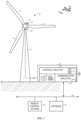
- FIG. 1 depicts a front view of a wind turbine generator 10 configured to convert wind energy into electrical energy.
- the wind turbine generator 10 includes a tower 12, a nacelle 14 and blades 16.
- the blades 16 are coupled to a generator 18 within the nacelle 14 by a hub 20 that rotates with the blades 16.
- the blades 16 are configured to convert the linear air flow from the wind into rotational motion.
- the coupling between the hub 20 and the generator 18 within the nacelle 14 drives components of the generator 18 to rotate, thereby producing electrical energy.
- three blades 16 are included in the depicted wind turbine generator 10, alternative implementations may include more or fewer blades 16.
- the wind turbine generator 10 may also include a controller 26 to control the operation of the wind turbine generator 10.
- the controller 26 may control the rotational speed (rpm) of the wind turbine generator 10, the pitch of the blades 16, the yaw of the wind turbine generator 10, as well as other parameters of operation.
- the controller 26 may include control circuitry 28, which may include a processor 30 and a memory component 32.
- the processor may be configured to analyze data, run programs, execute instructions, optimize operating parameters of the wind turbine generator 10, and control the operating parameters of the wind turbine generator 10.
- the memory component 32 may be any non-transitory computer readable medium.
- the memory component may store data, processor instructions, programs, optimization algorithms, lookup tables, models, and the like, including processor instructions for implementing the present approaches discussed herein. Though depicted as an aspect of the wind turbine generator 10, as discussed below the controller 26 may be implemented at the site level (i.e., a wind farm controller) that monitors and controls operation of a multitude of wind turbine systems 10 at a given site.
- the controller 26 may include or communicate with an operator interface 34.
- the operator interface 34 may include a display and/or operator inputs.
- the operator interface 34 allows the wind turbine generator 10 to communicate with and be controlled by the operator and the operator to communicate with the wind turbine generator 10.
- the various components of the controller 26 are shown within a common unit or housing for purposes of illustration, in some examples the various components (e.g., control circuitry 28, processor 30, memory 32, operator interface 34, display 36, operator inputs 38, communication circuitry 40, etc.) maybe situated in more than one unit and/or location (i.e., distributed).
- the controller 26 may also include communication circuitry 40.
- the communication circuitry may facilitate communication between the controller and an operator (e.g. via a smart device) by wired or wireless communication.
- the communication circuitry 40 may facilitate communication via a wireless or wired connection.
- a remote control system 46 and/or a database 48 may be in communication with the controller 26 via a connected network 44.
- the remote control system 46 may allow commands to be remotely issued to one or more wind turbine systems 10 spread across one or more locations.
- the network 44 may also provide access to one or more a databases 48 containing configuration and/or historical operational data.
- a drone 50 is shown as being in the vicinity of the wind turbine generator 10, such as to collect inspection data as discussed herein.
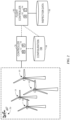
- FIG. 2 aspects of a system suitable for inspecting one or more assets, such as a multitude of wind turbine systems 10 provided as a wind farm 80, is described.
- the wind turbine generators 10 of the wind farm 80 are individually or collectively controlled or in communication with a controller 26, as previously described in the context of a single wind turbine generator 10.
- SCADA supervisory control and data acquisition protocols
- the SCADA protocols or routines may acquire operational data from each of the wind turbine generators 10 of the farm 80 and may control operation of the individual wind turbine generators 10, such as by sending operation commands or instructions to the respective wind turbine generators 10.
- some or all of the wind turbine generators 10 may include sensors that may measure environmental conditions and/or weather data relevant to the wind turbine generator 10 (such as wind speed, wind direction, atmospheric pressure, temperature, humidity, precipitation over a time period, atmospheric conditions, and so forth).
- the sensors may additionally or alternatively measure parameters related to the operation of the respective wind turbine generator 10, such as blade revolutions per minute, temperature, vibration, torque, hours used, electrical power production, and so forth.
- SCADA protocols associated with a given wind turbine generator or farm of wind turbine generators may be configured to determine one or more of an operating state, environmental or local conditions, and/or current operational parameters or characteristics for a given generator, such as a nacelle yaw, blade angles, operating state, and so forth for each generator.
- SCADA protocols may be configured to generate and transmit commands or instructions to the wind turbine generators 10 of the associated farm 80.
- commands to start and stop blade movement and/or commands to assume known or specified configurations, such as a "rabbit ear” command (in which, for a three-blade turbine, one blade is pointed downward and the other two are angled upwards, such as at 30° angles relative to the surface).
- a "rabbit ear" command in which, for a three-blade turbine, one blade is pointed downward and the other two are angled upwards, such as at 30° angles relative to the surface).
- the controller 26, and possibly any SCADA routines executing on the controller 26, is in communication with a configuration database 84.
- a configuration database 84 may be used to store and/or manage various configuration data for the wind turbine generators 10 of a respective wind farm 80.
- the configuration database may include model and/or serial numbers for one or more components, blade identifiers or numbers, color coding or visual markings associated with each blade, and so forth.
- FIG. 2 also depicts a flight controller 90 that is responsible for coordinating operation of one or more drones 50, such as for inspection of the wind turbine generators 10 of the farm 80.
- the drone(s) 50 have onboard cellular or network connectivity and can communicate with the flight controller 90 at least prior to beginning an inspection.
- the cellular or network connectivity of the drone(s) 50 allow communication during an inspection, allowing inspection data to be communicated to the flight controller 90 or other components (e.g., inspection data repository 98) and/or allowing the flight controllerto communicate changes to the flight plan to a given drone 50.
- the flight controller is depicted as a processor-based system having a one or more processors 94 and a memory 92.
- the processor 94 may execute routines stored in the memory 92 (and/or utilize data stored in the memory 92) to generate commands or flight plans for the drone(s) 50 used in an inspection process.
- the flight controller 90 is in communication with one or both of the wind turbine controller 26 and/or the configuration database 84 and may use information obtained from either source in the control of the drone(s) 50. Conversely, based on information or feedback received from the drone(s) 50, the flight controller 90 may update or issue instructions to the wind turbine controller 26 and/or the configuration database.
- the flight controller 90 may in certain examples be characterized as being an interface between the drone(s) 50 and the SCADA protocols employed to operate and monitor the wind turbine generators 10 of the farm 80, as well as interfacing with the configuration database 84 where appropriate.
- the flight controller 90 is depicted as in communication with an inspection data database 98, such as an image repository.
- an inspection data database 98 such as an image repository.
- videos, images, LIDAR data, or other relevant sensor or camera data acquired by the one or more drones 50 during an inspection may be uploaded to the inspection data database 98 as acquired or as a batch after an inspection flight plan is completed.
- the data within the inspection data database may then be reviewed or validated as part of the inspection process.
- acquired inspection data may be assessed in real time or near-real-time, in which case the flight controller 90 may on-the-fly update flight plan of a drone 50 if acquisition of additional inspection data is warranted (e.g., additional video or images from a different range or angle).
- Inspection or image data may also include images of the turbine blades 16 that include a visual identifier (e.g., an alphanumeric code, two-or three-dimensional bar code and so forth) that can be used to match and identify a given blade undergoing inspection.
- a visual identifier e.g., an alphanumeric code, two-or three-dimensional bar code and so forth
- OCR optical character recognition
- which blade of a generator is being inspected (or has been inspected) is determined using optical character recognition (OCR) techniques and/or a combination of OCR techniques and paint matching or color coding techniques to analyze marking on the blades, such as near the roots of the blades.
- OCR optical character recognition
- paint matching or color coding techniques to analyze marking on the blades, such as near the roots of the blades.
- blades may be matched using images acquired during an inspection compared to a stored repository of previously captured images. In this manner, during an inspection, a drone may be able to infer which blade of a wind turbine generator
- the turbine controller 26, flight controller 90, configuration database 84, and inspection database 98 are depicted as separate and discrete entities. However, it should be appreciated that, depending on the implementation, certain of these aspects may be provided as different functions or functionalities implemented by a single or common processor-based system. Conversely, the depicted functionalities may be implemented in a distributed or dispersed manner, with certain aspects being local to the wind farm 80 (such as the SCADA or wind turbine controller 26) and other remote from the wind farm 80 (such as the inspection database 98. In such distributed implementations, the depicted aspects may still be communicatively linked, such as over one or more network connections.
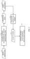
- FIG. 3 an example of algorithm steps in the initiation of an inspection operation are depicted. Such steps may be implemented by a processor of a system or component discussed herein to begin the steps of an asset inspection process.
- an initial command 120 may be received to begin an inspection, such as by a user interacting with a user interface of the flight controller 90 or turbine controller 26 to issue an inspection command.
- a step 124 is performed of acquiring environmental and/or operational data 126 for the asset or assets to be inspected.
- operating data 126 may include, but is not limited to, current weather or environmental conditions as well as data related to an operating state for the asset or assets undergoing inspection.
- location data 130 e.g., latitude and longitude
- location data 130 may be acquired either from the same source or from a separate data source.
- operating data 126 may be processed or transformed into higher-level constructs which may be used in subsequent processes.
- environmental data may be acquired at multiple locations so as to create a map or representation of localized conditions at different locations of the site.
- anemometers, wind vanes, and so forth may be used to acquire localized wind pattern data, which may vary for different locations within the wind farm.
- This localized wind pattern data may be represented as a map or other spatial representation which may be used to generate flight plans.
- further processing of the localized environment data based on knowledge of the drones to be employed in an inspection may allow generation of certain types of maps or spatial representations, such as a yaw offset map, that may be useful in flight planning, as discussed in greater detail below.
- an inspection order for the assets is calculated (block 134).
- a flight plan 140 may be generated.
- the flight plan may consist of a series of waypoints to which the drone or drones 50 travel in a specified order and/or at specified times.
- generation of the flight plan may take into account localized environmental conditions (e.g., wind speed and direction) and or estimated flight characteristics (e.g., yaw offset) in view of the localized environmental conditions and drone characteristics.
- one or more cameras or sensors may be activated to acquire inspection data.
- the flight plan (or waypoints of the flight plan) might also specify particular orientations to be exhibited by the drone(s) at given waypoints or while in motion between waypoints.
- the one or more drones may then be operated (block 144) in accordance with the inspection flight plan.
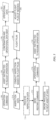
- FIG. 4 relates steps of an algorithm corresponding to a real-world implementation, here the inspection of wind turbine generators.
- the operator commands a drone inspection manager (DIM) computer-implemented routine or program to begin inspecting one or more wind turbine generators.
- the DIM program gathers (step 164) data from the respective wind farm SCADA via a communication (e.g., network) interface.
- the data gathered by the DIM from the SCADA includes, but is not limited to, current operating data, generated power, wind speed, and so forth.
- the DIM program calculates (step 168) a turbine inspection order based on turbine locations and current operating and/or environmental data.
- the turbine inspection order may be calculated so as to minimize lost production (i.e., power generation).
- the DIM program may launch one or more drones to inspect the wind generation turbines in the specified order.
- FIG. 5 an example of algorithm steps in the execution of an inspection operation are depicted. Some or all of the steps may be implemented by a processor of a system or component discussed herein to perform an asset inspection process.
- the inspection process involves coordination of the operation of both the asset and the drone.
- an operational command 190 may be issued to the asset to change (block 194) an aspect of its operation, such as to stop motion of some component that typically moves during operation.
- the asset may issue a confirmation (block 198) that the operational command 190 was executed and, in certain implementations, may provide current operational data 202 for the asset, such as the motion or operational state for various components, the position or orientation of components that may be mobile, the power state of the asset, localized environmental conditions (or flight characteristics, such as yaw offset, derived for the localized environmental conditions), and so forth.
- current operational data 202 for the asset such as the motion or operational state for various components, the position or orientation of components that may be mobile, the power state of the asset, localized environmental conditions (or flight characteristics, such as yaw offset, derived for the localized environmental conditions), and so forth.
- local wind speed and direction, or localized yaw offsets derived for the local wind conditions may be provided at this step.
- a flight controller 90 in communication with the drone(s) 50 may make adjustments (block 206) to the flight plan 140 if justified and convey the modified flight plan 140 to the drone 50.
- certain onboard navigational capability may be provided on the drone 50 itself and, in response to receipt of operational data 202, flight plan adjustments may be made by processing components on the drone itself.
- yaw offset for a given drone, location and sequence of way points, and so forth may be updated based on most recent or real-time wind data obtained at an inspection site.
- wind data or a yaw offset map derived for such wind data may be monitored in real-time or near-real-time for changes and/or deviations from expected values and, in response to such changes or deviations (or in expectation of expected changes or deviations), a flight plan 140 may be modified on periodically or on-the-fly.
- the drone(s) 50 may conduct (block 210) an inspection executing the flight plan 140, i.e., by moving along the flight plan to the various waypoints under the temporal constraints specified and operating one or more cameras or sensors based on the flight plan 140.
- the drone By moving along the flight plan as instructed and operating its sensors and/or cameras the drone generates a set of inspection data 214.
- the inspection data 214 may be processed (block 218) in real time or near-real time, such as to determine the completeness of the inspection data 214 or to determine if the inspection data 214 indicates a potential problem for which additional data should be collected.
- the flight plan 140 may be updated and the inspection resumed to collect whatever additional inspection data is needed.
- the inspection data 214 is not downloaded until the drone(s) 50 return to their base location, at which time the inspection data 214 may be processed or analyzed.
- a restart command 226 may be sent (block 222) to the asset, instructing it to resume (block 230) operation if some aspect of operation was stopped or modified for the inspection.
- the drone 50 may proceed (block 234) to the next asset, such as in accordance with the flight plan 140.
- the next asset to be inspected may be issued an operational command 190 to stop or modify its operation (block 194) once the drone(s) 50 approach the asset, beginning the process shown in FIG. 5 once again.
- FIG. 5 represents a generalized inspection process flow
- FIG. 6 relates steps of a process flow corresponding to a real-world implementation, here the inspection of wind turbine generators.
- the present approach integrates the SCADA operating data for a wind turbine generator to command or adjust operation of the turbines when an inspection drone approaches (e.g., mid-flight) on the basis of drone approach.
- an inspection drone approaches e.g., mid-flight
- DIM drone inspection manager
- the SCADA sends a stop command to the respective wind turbine generator 10.
- the wind turbine generator 10 stops (block 258) rotation of its blades, such as by going into a rabbit ear blade orientation, and sends a confirmation to the DIM ton confirm a stopped operational state.
- the SCADA determines the nacelle yaw and blade position of the respective wind turbine generator and sends (block 262) this information to the DIM.
- the DIM communicates (block 266) the flight plan to one or more drones 50 which will inspect the wind turbine generator.
- the drone(s) inspect (block 270) the wind turbine generator in accordance with the flight plan.
- the drone(s) 50 send imagery data back to the DIM, such as over an encrypted network connection.
- the drone(s) 50 leave (block 274) the wind turbine generator and the DIM sends a restart command to the SCADA.
- the SCADA instructs the wind turbine generator to resume operation (block 278). If additional wind turbine generators are to be inspected, the drone(s) 50 move to the next inspection target (block 282) and the process is repeated. In all generators have been inspected, the drone(s) return to base.
- Technical effects of the disclosure include a system that integrates operating data from a wind turbine (or other asset) to adjust a flight path or otherwise control a drone conducting an inspection. Based on the proximity of the drone and the status of the inspection, the operation of the asset (e.g., wind turbine) may also be adapted or adjusted, facilitating inspection of those parts of the asset that move during operation.
- a wind turbine or other asset
- the operation of the asset e.g., wind turbine
Landscapes
- Engineering & Computer Science (AREA)
- Physics & Mathematics (AREA)
- General Physics & Mathematics (AREA)
- Aviation & Aerospace Engineering (AREA)
- Automation & Control Theory (AREA)
- Radar, Positioning & Navigation (AREA)
- Remote Sensing (AREA)
- Business, Economics & Management (AREA)
- Strategic Management (AREA)
- Entrepreneurship & Innovation (AREA)
- Human Resources & Organizations (AREA)
- Economics (AREA)
- Life Sciences & Earth Sciences (AREA)
- General Engineering & Computer Science (AREA)
- Mechanical Engineering (AREA)
- Combustion & Propulsion (AREA)
- Chemical & Material Sciences (AREA)
- Sustainable Energy (AREA)
- Sustainable Development (AREA)
- Development Economics (AREA)
- Theoretical Computer Science (AREA)
- General Business, Economics & Management (AREA)
- Tourism & Hospitality (AREA)
- Quality & Reliability (AREA)
- Operations Research (AREA)
- Marketing (AREA)
- Game Theory and Decision Science (AREA)
- Educational Administration (AREA)
- Wind Motors (AREA)
- Control Of Position, Course, Altitude, Or Attitude Of Moving Bodies (AREA)
- Testing And Monitoring For Control Systems (AREA)
Description
- The subject matter disclosed herein relates to inspection of an asset, such as a system, device, or facility, using one or more robotic agents such as drones or other unmanned vehicles.
- Various entities may own or maintain different types of assets as part of their operation. Such assets may include physical or mechanical devices, structures, or facilities which may, in some instances, have electrical and/or chemical aspects as well. Such assets may be used or maintained for a variety of purposes and may be characterized as capital infrastructure, inventory, or by other nomenclature depending on the context. For example, assets may include distributed assets, such as a pipeline or an electrical grid as well as individual or discrete assets, such as an airplane, a wind turbine generator, a tower, a vehicle, and so forth. Assets may be subject to various types of defects (e.g., spontaneous mechanical defects, electrical defects as well as routine wear-and-tear) that may impact their operation. For example, over time, the asset may undergo corrosion or cracking due to weather or may exhibit deteriorating performance or efficiency due to the wear or failure of component parts.
- Typically, one or more human inspectors may inspect, maintain, and repair the asset. For example, the inspector may locate corrosion on the asset, may locate and quantitatively or qualitatively assess cracks or defects on the asset, may assess an asset for the degree of wear-and-tear observed versus what is expected, and so forth. However, depending on the location, size, and/or complexity of the asset, having one or more human inspectors performing inspection of the asset may take away time for the inspectors to perform other tasks or may otherwise be time consuming and labor intensive, requiring personnel time that might be more productively spent elsewhere. Additionally, some inspection tasks may be dull, dirty, or may be otherwise unsuitable for a human to perform. For instance, some assets may have locations that may not be accessible to humans due to height, confined spaces, or the like. Further, inspections may be performed at times that are based on schedules resulting in either over-inspection or under-inspection.
- Further, some assets may, due to the nature of their operation, be difficult to inspect or assess while in operation, such as due to moving or inaccessible parts. Thus, an inspection may be either incomplete or may require that the asset be taken offline, and therefore unproductive, during the inspection process. Such outcomes may be undesirable. Further, due to the uncertain nature of the inspection process, i.e., current inspection findings may impact subsequent scheduling, it may be difficult to schedule asset downtime so as to minimize the impact of the inspection process.
CN 204 536 215 U relates to wind power equipment detection techniques, specifically a fault detection system for a wind-power blade.US 2016/0292869 A1 also discloses a system for inspecting an asset like a wind turbine by using drones. - In a first aspect, there is provided an asset inspection system according to claim 1. In a second aspect, there is provided a method for inspecting an asset according to claim 6. Other aspects and features are set out in the dependent claims. Certain examples commensurate in scope with the originally claimed disclosure are summarized below. These examples are not intended to limit the scope of the claimed disclosure, but rather these examples are intended only to provide a brief summary of possible forms of the disclosure. Indeed, examples may encompass a variety of forms that may be similar to or different from the examples set forth below.
- In one example, an asset inspection system is provided. In accordance with this example, the asset inspection system includes: an asset controller configured to monitor one or more parameters associated with one or more assets and to control operation of the one or more assets; one or more drones; and a flight controller configured to communicate with the one or more drones and the asset controller and to coordinate operation of the asset with a flight plan followed by the one or more drones during an inspection.
- In an additional example, a method for inspecting an asset is provided. In accordance with this method, a first operational command to adjust operation of an asset is sent as one or more drones approach the asset to perform an inspection. A confirmation is received that the operational command has been performed by the asset. The one or more drones are instructed to execute a flight plan with respect the asset and to collect inspection data when executing the flight plan. Upon completion of the flight plan, A second operational command is sent to return the asset to normal operation.
- These and other features, aspects, and advantages of the present disclosure will become better understood when the following detailed description is read with reference to the accompanying drawings in which like characters represent like parts throughout the drawings, wherein:
-
FIG. 1 shows a wind turbine system configured to convert wind energy into electrical energy in accordance with aspects of the present disclosure; -
FIG. 2 is a block diagram of an example of wind power system site having use of a drone-based inspection system, in accordance with aspects of the present disclosure; -
FIG. 3 depicts a process flow of an inspection initiation flow, in accordance with aspects of the present disclosure; -
FIG. 4 depicts a process flow of a wind turbine generator inspection initiation flow, in accordance with aspects of the present disclosure; -
FIG. 5 depicts a process flow of an inspection flow, in accordance with aspects of the present disclosure; and -
FIG. 6 depicts a process flow of a wind turbine generator inspection flow, in accordance with aspects of the present disclosure. - One or more specific examples will be described below. In an effort to provide a concise description of these examples, all features of an actual implementation may not be described in the specification. It should be appreciated that in the development of any such actual implementation, as in any engineering or design project, numerous implementation-specific decisions must be made to achieve the developers' specific goals, such as compliance with system-related and business-related constraints, which may vary from one implementation to another. Moreover, it should be appreciated that such a development effort might be complex and time consuming, but would nevertheless be a routine undertaking of design, fabrication, and manufacture for those of ordinary skill having the benefit of this disclosure.
- When introducing elements of various examples of the present disclosure, the articles "a," "an," "the," and "said" are intended to mean that there are one or more of the elements. The terms "comprising," "including," and "having" are intended to be inclusive and mean that there may be additional elements other than the listed elements. Furthermore, any numerical examples in the following discussion are intended to be non-limiting, and thus additional numerical values, ranges, and percentages are within the scope of the disclosed examples.
- As discussed herein, the present approach relates to the inspection of one or more assets, such as power generation assets, transportation assets, mining or underground pumping assets, manufacture or construction assets and so forth, using unmanned or robotic devices, such as unmanned aerial vehicles (UAVs), unmanned submersible vehicles (USVs), or other autonomously moving vehicles that may be characterized as drones or robots. For simplicity, the term "drone" is used herein, though it should be appreciated that this terminology is intended to encompass all variations, of UAVs, USVs, robotic devices, and so forth that are capable of programmable movement with no or limited human oversight. Such programmable movement can be based on either locally generated path waypoints or guidance or path guidance and waypoints generated by a remote system and communicated to the drone. Thus, as used herein, such devices move during an operational phase or period entirely or primarily without direct human intervention or control and/or with limited human intervention or oversight. In accordance with present approaches, such devices may be operated to move along a flight plan, along which the devices acquire inspection data, such as video or still image data, LIDAR data, or other data that can be acquired by sensors or cameras that can be affixed to a device moving along the flight plan.
- Though the phrase "flight plan" is used generally herein, it should be appreciated that this phrase does not necessitate aerial movement, but instead relates to any one-dimensional (1D) (such as along a track), two-dimensional (2D) (such as along a defined or undefined planar route), or three-dimensional (3D) (such as movement in the air, under water, or on a structure in where depth or altitude is also traversable), or four-dimensional (4D) (such as where there are defined temporal aspects) path or route along which a drone moves as part of an inspection plan. Thus, a "flight plan" as used herein may be characterized as any 1D, 2D, 3D, or 4D route or path along which device such as a drone or robot is moved to perform a sensor-based inspection of an asset. Such a path may be adaptive, as discussed herein, and may consist of one or more waypoints along which the drone proceeds in an ordered fashion, with the sequence and location of the waypoints defining the path or route. It should be appreciated that such a flight plan may also incorporate not only temporal and/or spatial locations, but also orientation and/or alignment instructions for movement along the path and/or to exhibit at a given waypoint. Thus, the flight plan may also specify parameters such as roll, pitch, and yaw for the drone to exhibit at different points along the flight plan as well as two- or three-dimensional alignment characteristics that may relate to the direction in which a sensor or camera is pointing at a point along the flight plan. Thus, the flight plan may address not only where or when a drone is with respect to an inspection site but, at a given location or waypoint, the direction the drone is facing or otherwise oriented with respect to.
- As discussed herein, the present approach facilitates the inspection of assets that may otherwise be difficult to inspect when operated, such as assets having moving parts which themselves need to be inspected or which generate an environment that would otherwise be hostile to the inspection process. As discussed herein, operational data for the asset may be incorporated into planning or adapting the flight plan and/or operational commands may be issued to asset in accordance with the flight plan to facilitate acquisition of the needed inspection data.
- To facilitate explanation and provide useful real-world context, an example of a wind farm having multiple wind turbine generators is discussed herein. It should be appreciated however that such an example is provided merely to facilitate explanation, and the present approach is suitable for use with a wide range of other assets and at various other types of sites. Thus, the present approach is not intended to be limited to the context of the present examples.
- With the preceding in mind, and turning to the figures,
FIG. 1 depicts a front view of awind turbine generator 10 configured to convert wind energy into electrical energy. Thewind turbine generator 10 includes atower 12, anacelle 14 andblades 16. Theblades 16 are coupled to agenerator 18 within thenacelle 14 by ahub 20 that rotates with theblades 16. Theblades 16 are configured to convert the linear air flow from the wind into rotational motion. As theblades 16 rotate, the coupling between thehub 20 and thegenerator 18 within thenacelle 14 drives components of thegenerator 18 to rotate, thereby producing electrical energy. While threeblades 16 are included in the depictedwind turbine generator 10, alternative implementations may include more orfewer blades 16. - The
wind turbine generator 10 may also include acontroller 26 to control the operation of thewind turbine generator 10. For example, thecontroller 26 may control the rotational speed (rpm) of thewind turbine generator 10, the pitch of theblades 16, the yaw of thewind turbine generator 10, as well as other parameters of operation. Thecontroller 26 may includecontrol circuitry 28, which may include aprocessor 30 and amemory component 32. The processor may be configured to analyze data, run programs, execute instructions, optimize operating parameters of thewind turbine generator 10, and control the operating parameters of thewind turbine generator 10. Thememory component 32 may be any non-transitory computer readable medium. The memory component may store data, processor instructions, programs, optimization algorithms, lookup tables, models, and the like, including processor instructions for implementing the present approaches discussed herein. Though depicted as an aspect of thewind turbine generator 10, as discussed below thecontroller 26 may be implemented at the site level (i.e., a wind farm controller) that monitors and controls operation of a multitude ofwind turbine systems 10 at a given site. - In the depicted example, the
controller 26 may include or communicate with anoperator interface 34. Theoperator interface 34 may include a display and/or operator inputs. Theoperator interface 34 allows thewind turbine generator 10 to communicate with and be controlled by the operator and the operator to communicate with thewind turbine generator 10. Though the various components of thecontroller 26 are shown within a common unit or housing for purposes of illustration, in some examples the various components (e.g.,control circuitry 28,processor 30,memory 32,operator interface 34, display 36, operator inputs 38,communication circuitry 40, etc.) maybe situated in more than one unit and/or location (i.e., distributed). - The
controller 26 may also includecommunication circuitry 40. In some examples, the communication circuitry may facilitate communication between the controller and an operator (e.g. via a smart device) by wired or wireless communication. In some examples, thecommunication circuitry 40 may facilitate communication via a wireless or wired connection. In some examples, aremote control system 46 and/or a database 48 (such as a configuration database as discussed below) may be in communication with thecontroller 26 via a connectednetwork 44. Theremote control system 46 may allow commands to be remotely issued to one or morewind turbine systems 10 spread across one or more locations. Thenetwork 44 may also provide access to one or more adatabases 48 containing configuration and/or historical operational data. - In the depicted example a drone 50 is shown as being in the vicinity of the
wind turbine generator 10, such as to collect inspection data as discussed herein. - Turning to
FIG. 2 , aspects of a system suitable for inspecting one or more assets, such as a multitude ofwind turbine systems 10 provided as a wind farm 80, is described. In this example, thewind turbine generators 10 of the wind farm 80 are individually or collectively controlled or in communication with acontroller 26, as previously described in the context of a singlewind turbine generator 10. - By way of example, at the local site (i.e., wind farm 80), SCADA (supervisory control and data acquisition) protocols may be executed on the controller 26 (or as part of other circuit or processor implementations) as part of the ongoing operation and oversight of the wind farm 80. In such an implementation, the SCADA protocols or routines, when implemented, may acquire operational data from each of the
wind turbine generators 10 of the farm 80 and may control operation of the individualwind turbine generators 10, such as by sending operation commands or instructions to the respectivewind turbine generators 10. - To facilitate such operational monitoring and control by the SCADA routines, some or all of the
wind turbine generators 10 may include sensors that may measure environmental conditions and/or weather data relevant to the wind turbine generator 10 (such as wind speed, wind direction, atmospheric pressure, temperature, humidity, precipitation over a time period, atmospheric conditions, and so forth). The sensors may additionally or alternatively measure parameters related to the operation of the respectivewind turbine generator 10, such as blade revolutions per minute, temperature, vibration, torque, hours used, electrical power production, and so forth. - Thus the SCADA protocols associated with a given wind turbine generator or farm of wind turbine generators may be configured to determine one or more of an operating state, environmental or local conditions, and/or current operational parameters or characteristics for a given generator, such as a nacelle yaw, blade angles, operating state, and so forth for each generator. In addition, the SCADA protocols may be configured to generate and transmit commands or instructions to the
wind turbine generators 10 of the associated farm 80. Examples of such commands include, but are not limited to, commands to start and stop blade movement (and corresponding power generation) and/or commands to assume known or specified configurations, such as a "rabbit ear" command (in which, for a three-blade turbine, one blade is pointed downward and the other two are angled upwards, such as at 30° angles relative to the surface). - In the depicted example, the
controller 26, and possibly any SCADA routines executing on thecontroller 26, is in communication with aconfiguration database 84. Such aconfiguration database 84 may be used to store and/or manage various configuration data for thewind turbine generators 10 of a respective wind farm 80. For example, for eachwind turbine generator 10, the configuration database may include model and/or serial numbers for one or more components, blade identifiers or numbers, color coding or visual markings associated with each blade, and so forth. -
FIG. 2 also depicts aflight controller 90 that is responsible for coordinating operation of one or more drones 50, such as for inspection of thewind turbine generators 10 of the farm 80. In one example, the drone(s) 50 have onboard cellular or network connectivity and can communicate with theflight controller 90 at least prior to beginning an inspection. In certain implementations the cellular or network connectivity of the drone(s) 50 allow communication during an inspection, allowing inspection data to be communicated to theflight controller 90 or other components (e.g., inspection data repository 98) and/or allowing the flight controllerto communicate changes to the flight plan to a given drone 50. - In the depicted example, the flight controller is depicted as a processor-based system having a one or more processors 94 and a memory 92. For example, the processor 94 may execute routines stored in the memory 92 (and/or utilize data stored in the memory 92) to generate commands or flight plans for the drone(s) 50 used in an inspection process. In the depicted example, the
flight controller 90 is in communication with one or both of thewind turbine controller 26 and/or theconfiguration database 84 and may use information obtained from either source in the control of the drone(s) 50. Conversely, based on information or feedback received from the drone(s) 50, theflight controller 90 may update or issue instructions to thewind turbine controller 26 and/or the configuration database. Thus, theflight controller 90 may in certain examples be characterized as being an interface between the drone(s) 50 and the SCADA protocols employed to operate and monitor thewind turbine generators 10 of the farm 80, as well as interfacing with theconfiguration database 84 where appropriate. - In addition, the
flight controller 90 is depicted as in communication with aninspection data database 98, such as an image repository. By way of example, videos, images, LIDAR data, or other relevant sensor or camera data acquired by the one or more drones 50 during an inspection may be uploaded to theinspection data database 98 as acquired or as a batch after an inspection flight plan is completed. The data within the inspection data database may then be reviewed or validated as part of the inspection process. In certain implementations, acquired inspection data (e.g., sensors readings, video, still images) may be assessed in real time or near-real-time, in which case theflight controller 90 may on-the-fly update flight plan of a drone 50 if acquisition of additional inspection data is warranted (e.g., additional video or images from a different range or angle). - Inspection or image data may also include images of the
turbine blades 16 that include a visual identifier (e.g., an alphanumeric code, two-or three-dimensional bar code and so forth) that can be used to match and identify a given blade undergoing inspection. By way of example, in one example related to turbine blade inspection, which blade of a generator is being inspected (or has been inspected) is determined using optical character recognition (OCR) techniques and/or a combination of OCR techniques and paint matching or color coding techniques to analyze marking on the blades, such as near the roots of the blades. For example, using these techniques, blades may be matched using images acquired during an inspection compared to a stored repository of previously captured images. In this manner, during an inspection, a drone may be able to infer which blade of a wind turbine generator is which. - In the depicted example, the
turbine controller 26,flight controller 90,configuration database 84, andinspection database 98 are depicted as separate and discrete entities. However, it should be appreciated that, depending on the implementation, certain of these aspects may be provided as different functions or functionalities implemented by a single or common processor-based system. Conversely, the depicted functionalities may be implemented in a distributed or dispersed manner, with certain aspects being local to the wind farm 80 (such as the SCADA or wind turbine controller 26) and other remote from the wind farm 80 (such as theinspection database 98. In such distributed implementations, the depicted aspects may still be communicatively linked, such as over one or more network connections. - Turning to
FIG. 3 , an example of algorithm steps in the initiation of an inspection operation are depicted. Such steps may be implemented by a processor of a system or component discussed herein to begin the steps of an asset inspection process. In this example, aninitial command 120 may be received to begin an inspection, such as by a user interacting with a user interface of theflight controller 90 orturbine controller 26 to issue an inspection command. - In the depicted example, in response to the
inspection command 120, astep 124 is performed of acquiring environmental and/oroperational data 126 for the asset or assets to be inspected.Such operating data 126 may include, but is not limited to, current weather or environmental conditions as well as data related to an operating state for the asset or assets undergoing inspection. In addition, location data 130 (e.g., latitude and longitude) for the asset or assets may be acquired either from the same source or from a separate data source. - In certain implementations, operating
data 126, including weather or environmental data, may be processed or transformed into higher-level constructs which may be used in subsequent processes. By way of example, for a given location, such as a wind farm site, environmental data may be acquired at multiple locations so as to create a map or representation of localized conditions at different locations of the site. For instance, in the context of a wind farm, anemometers, wind vanes, and so forth may be used to acquire localized wind pattern data, which may vary for different locations within the wind farm. This localized wind pattern data may be represented as a map or other spatial representation which may be used to generate flight plans. Similarly, further processing of the localized environment data based on knowledge of the drones to be employed in an inspection may allow generation of certain types of maps or spatial representations, such as a yaw offset map, that may be useful in flight planning, as discussed in greater detail below. - Based on the operating
data 126 andlocations 130, an inspection order for the assets, if more than one is to be inspected, is calculated (block 134). From the inspection order, aflight plan 140 may be generated. The flight plan, as noted above, may consist of a series of waypoints to which the drone or drones 50 travel in a specified order and/or at specified times. As noted above, generation of the flight plan may take into account localized environmental conditions (e.g., wind speed and direction) and or estimated flight characteristics (e.g., yaw offset) in view of the localized environmental conditions and drone characteristics. - At certain of the waypoints on the
flight plan 140, one or more cameras or sensors may be activated to acquire inspection data. As noted above, the flight plan (or waypoints of the flight plan) might also specify particular orientations to be exhibited by the drone(s) at given waypoints or while in motion between waypoints. The one or more drones may then be operated (block 144) in accordance with the inspection flight plan. - While
FIG. 3 represents a generalized flight plan generation algorithm,FIG. 4 relates steps of an algorithm corresponding to a real-world implementation, here the inspection of wind turbine generators. In this example, atstep 160 the operator commands a drone inspection manager (DIM) computer-implemented routine or program to begin inspecting one or more wind turbine generators. In response to this instruction, the DIM program gathers (step 164) data from the respective wind farm SCADA via a communication (e.g., network) interface. In one implementation, the data gathered by the DIM from the SCADA includes, but is not limited to, current operating data, generated power, wind speed, and so forth. Based on the collected data, the DIM program calculates (step 168) a turbine inspection order based on turbine locations and current operating and/or environmental data. By way of example, the turbine inspection order may be calculated so as to minimize lost production (i.e., power generation). Based on the turbine inspection order, atstep 172 the DIM program may launch one or more drones to inspect the wind generation turbines in the specified order. - Turning to
FIG. 5 , an example of algorithm steps in the execution of an inspection operation are depicted. Some or all of the steps may be implemented by a processor of a system or component discussed herein to perform an asset inspection process. In this example, the inspection process involves coordination of the operation of both the asset and the drone. For example, starting atstep 190, as a drone 50 performing an inspection approaches an asset to be inspected, anoperational command 190 may be issued to the asset to change (block 194) an aspect of its operation, such as to stop motion of some component that typically moves during operation. In the depicted example, the asset, or a controller in communication with the asset, may issue a confirmation (block 198) that theoperational command 190 was executed and, in certain implementations, may provide currentoperational data 202 for the asset, such as the motion or operational state for various components, the position or orientation of components that may be mobile, the power state of the asset, localized environmental conditions (or flight characteristics, such as yaw offset, derived for the localized environmental conditions), and so forth. By way of example, local wind speed and direction, or localized yaw offsets derived for the local wind conditions, may be provided at this step. - Based on the
operational command 190 being sent and/or on a confirmation oroperational data 202 being received, aflight controller 90 in communication with the drone(s) 50 may make adjustments (block 206) to theflight plan 140 if justified and convey the modifiedflight plan 140 to the drone 50. Alternatively, in certain examples, certain onboard navigational capability may be provided on the drone 50 itself and, in response to receipt ofoperational data 202, flight plan adjustments may be made by processing components on the drone itself. By way of example, yaw offset for a given drone, location and sequence of way points, and so forth may be updated based on most recent or real-time wind data obtained at an inspection site. In one such example, wind data or a yaw offset map derived for such wind data may be monitored in real-time or near-real-time for changes and/or deviations from expected values and, in response to such changes or deviations (or in expectation of expected changes or deviations), aflight plan 140 may be modified on periodically or on-the-fly. - Based on the
flight plan 140, the drone(s) 50 may conduct (block 210) an inspection executing theflight plan 140, i.e., by moving along the flight plan to the various waypoints under the temporal constraints specified and operating one or more cameras or sensors based on theflight plan 140. By moving along the flight plan as instructed and operating its sensors and/or cameras the drone generates a set ofinspection data 214. In one example, theinspection data 214 may be processed (block 218) in real time or near-real time, such as to determine the completeness of theinspection data 214 or to determine if theinspection data 214 indicates a potential problem for which additional data should be collected. In such scenarios, theflight plan 140 may be updated and the inspection resumed to collect whatever additional inspection data is needed. In other implementations, theinspection data 214 is not downloaded until the drone(s) 50 return to their base location, at which time theinspection data 214 may be processed or analyzed. - In the depicted example, after acquisition of the
inspection data 214, arestart command 226 may be sent (block 222) to the asset, instructing it to resume (block 230) operation if some aspect of operation was stopped or modified for the inspection. In addition, if additional assets are to be inspected, the drone 50 may proceed (block 234) to the next asset, such as in accordance with theflight plan 140. In such a circumstance, the next asset to be inspected may be issued anoperational command 190 to stop or modify its operation (block 194) once the drone(s) 50 approach the asset, beginning the process shown inFIG. 5 once again. - While
FIG. 5 represents a generalized inspection process flow,FIG. 6 relates steps of a process flow corresponding to a real-world implementation, here the inspection of wind turbine generators. Unlike prior approaches, the present approach, as described below, integrates the SCADA operating data for a wind turbine generator to command or adjust operation of the turbines when an inspection drone approaches (e.g., mid-flight) on the basis of drone approach. In this example, atstep 250 drone inspection manager (DIM) routines, such as may be implemented as part of aflight controller 90, send a stop command to a SCADA in communication with awind turbine generator 10 to be inspected. In response, atstep 254 the SCADA sends a stop command to the respectivewind turbine generator 10. Upon receipt of the stop command, thewind turbine generator 10 stops (block 258) rotation of its blades, such as by going into a rabbit ear blade orientation, and sends a confirmation to the DIM ton confirm a stopped operational state. In the depicted example, once the wind turbine generator is stopped, the SCADA determines the nacelle yaw and blade position of the respective wind turbine generator and sends (block 262) this information to the DIM. Based on the operational data received from the SCADA, the DIM communicates (block 266) the flight plan to one or more drones 50 which will inspect the wind turbine generator. The drone(s) inspect (block 270) the wind turbine generator in accordance with the flight plan. In this example, the drone(s) 50 send imagery data back to the DIM, such as over an encrypted network connection. - Once the inspection is completed, the drone(s) 50 leave (block 274) the wind turbine generator and the DIM sends a restart command to the SCADA. In response to the restart command, the SCADA instructs the wind turbine generator to resume operation (block 278). If additional wind turbine generators are to be inspected, the drone(s) 50 move to the next inspection target (block 282) and the process is repeated. In all generators have been inspected, the drone(s) return to base.
- Technical effects of the disclosure include a system that integrates operating data from a wind turbine (or other asset) to adjust a flight path or otherwise control a drone conducting an inspection. Based on the proximity of the drone and the status of the inspection, the operation of the asset (e.g., wind turbine) may also be adapted or adjusted, facilitating inspection of those parts of the asset that move during operation.
- This written description uses examples in the disclosure, including the best mode, and also to enable any person skilled in the art to practice the disclosure, including making and using any devices or systems and performing any incorporated methods. The patentable scope of the disclosure is defined by the claims, and may include other examples that occur to those skilled in the art. Such other examples are intended to be within the scope of the claims if they have structural elements that do not differ from the literal language of the claims, or if they include equivalent structural elements with insubstantial differences from the literal languages of the claims.
Claims (10)
- An asset inspection system, comprising:an asset controller (26) configured to monitor one or more parameters associated with one or more assets (10) and to control operation of the one or more assets (10);one or more drones (50); anda flight controller (90) configured to communicate with the one or more drones (50) and the asset controller (26) and to coordinate operation of the asset (10) with a flight plan followed by the one or more drones (50) during an inspection, characterised in thatthe asset inspection system is configured to adjust the flight plan based on a yaw offset map generated at least in part using current environmental data.
- The asset inspection system of claim 1, wherein the one or more assets comprise:one or more of a power generation asset, a pipeline, an electrical grid, and a vehicle; ora wind turbine generator.
- The asset inspection system of claim 1, further comprising:a configuration database (84) configured to store or manage configuration data for the one or more assets; and/oran inspection data repository (98) configured to receive inspection data generated by the one or more drones for the one or more assets.
- The asset inspection system of claim 1, wherein the asset controller (26) is configured to stop operation of a respective asset (10) based on a first communication from the flight controller (90) that a drone (50) is approaching for an inspection and to start operation of the asset (10) based on a second communication from the flight controller (90) that the drone (50) has completed inspection of the respective asset (10).
- The asset inspection system of claim 1, wherein the asset controller (26) comprises a processor-based system executing one or more supervisory control and data acquisition (SCADA) protocols.
- A method for inspecting an asset (10), the method comprising:sending a first operational command to adjust operation of an asset (10) as one or more drones (50) approach the asset to perform an inspection;receiving a confirmation that the first operational command has been performed by the asset (10);instructing the one or more drones (50) to execute a flight plan with respect to the asset (10) and to collect inspection data when executing the flight plan;adjusting the flight plan based on a yaw offset map generated at least in part using current environmental data; andupon completion of the flight plan, sending a second operational command to return the asset (10) to normal operation.
- The method of claim 6, wherein the first operational command to adjust operation of the asset (10) comprises a stop operation command and wherein the second operational command comprises a restart operation command.
- The method of claim 6, further comprising:
adjusting the flight plan based on operational data received for the asset (10). - The method of claim 6, further comprising:
transmitting the inspection data to an inspection data repository (98) during or after the inspection. - The method of claim 6, further comprising:analyzing the flight plan before completion of the flight plan;modifying the flight plan based upon the results of analysis to create a modified flight plan; andexecuting the modified flight plan prior to sending the second operation command.
Applications Claiming Priority (2)
| Application Number | Priority Date | Filing Date | Title |
|---|---|---|---|
| US15/457,410 US10329017B2 (en) | 2017-03-13 | 2017-03-13 | System and method for integrating flight path and site operating data |
| PCT/US2018/018757 WO2018169652A1 (en) | 2017-03-13 | 2018-02-20 | System and method for integrating flight path and site operating data |
Publications (3)
| Publication Number | Publication Date |
|---|---|
| EP3596569A1 EP3596569A1 (en) | 2020-01-22 |
| EP3596569A4 EP3596569A4 (en) | 2021-01-06 |
| EP3596569B1 true EP3596569B1 (en) | 2023-05-03 |
Family
ID=63444943
Family Applications (1)
| Application Number | Title | Priority Date | Filing Date |
|---|---|---|---|
| EP18766897.5A Active EP3596569B1 (en) | 2017-03-13 | 2018-02-20 | System and method for integrating flight path and site operating data |
Country Status (6)
| Country | Link |
|---|---|
| US (2) | US10329017B2 (en) |
| EP (1) | EP3596569B1 (en) |
| JP (1) | JP7450389B2 (en) |
| KR (2) | KR102544411B1 (en) |
| CN (2) | CN110431501B (en) |
| WO (1) | WO2018169652A1 (en) |
Families Citing this family (59)
| Publication number | Priority date | Publication date | Assignee | Title |
|---|---|---|---|---|
| US10739770B2 (en) * | 2018-01-16 | 2020-08-11 | General Electric Company | Autonomously-controlled inspection platform with model-based active adaptive data collection |
| US10761526B2 (en) * | 2017-11-06 | 2020-09-01 | General Electric Company | Systems and method for robotic industrial inspection system |
| WO2017116860A1 (en) | 2015-12-31 | 2017-07-06 | Unmanned Innovation, Inc. | Unmanned aerial vehicle rooftop inspection system |
| US10329017B2 (en) * | 2017-03-13 | 2019-06-25 | General Electric Company | System and method for integrating flight path and site operating data |
| CN108986071B (en) * | 2018-05-31 | 2020-12-01 | 上海扩博智能技术有限公司 | Blade automatic detection and tracking method, system, equipment and storage medium |
| US12216105B2 (en) | 2018-06-19 | 2025-02-04 | Seekops Inc. | Localization analytics algorithms and methods |
| WO2019246280A1 (en) | 2018-06-19 | 2019-12-26 | Seekops Inc. | Emissions estimate model algorithms and methods |
| US12399164B2 (en) | 2018-06-19 | 2025-08-26 | Seekops Inc. | Emissions estimate model algorithms and methods |
| US10970586B2 (en) * | 2018-06-28 | 2021-04-06 | General Electric Company | Systems and methods of 3D scene segmentation and matching for robotic operations |
| US12044666B2 (en) | 2018-07-30 | 2024-07-23 | Seekops Inc. | Ultra-lightweight, handheld gas leak detection device |
| US11281200B2 (en) * | 2018-10-01 | 2022-03-22 | Fisher-Rosemount Systems, Inc. | Drone-enabled operator rounds |
| WO2020086499A1 (en) | 2018-10-22 | 2020-04-30 | Seekops Inc. | A uav-borne, high-bandwidth, lightweight point sensor for quantifying greenhouse gases in atmospheric strata |
| BR112021012919A2 (en) * | 2018-12-31 | 2023-02-14 | Sentient Science Corp | METHOD AND SYSTEM FOR DETERMINING A DAMAGE STATUS OF A WIND TURBINE GEARBOX, AND, TANGIBLE, NON-TRANSIENT, COMPUTER READABLE MEDIA |
| WO2020206006A1 (en) | 2019-04-05 | 2020-10-08 | Seekops Inc. | Analog signal processing for a lightweight and compact laser-based trace gas sensor |
| WO2020206020A1 (en) | 2019-04-05 | 2020-10-08 | Seekops Inc. | Route optimization for energy industry infrastructure inspection |
| US12188847B2 (en) | 2019-04-05 | 2025-01-07 | Seekops Inc. | Time-and data-efficient assurance of leak detection |
| US11455771B2 (en) * | 2019-05-15 | 2022-09-27 | Electronic Theatre Controls, Inc. | Venue survey using unmanned aerial vehicle |
| CN110322161A (en) * | 2019-07-10 | 2019-10-11 | 中国民航信息网络股份有限公司 | Flight comes into force come into force method of adjustment and the device of batch |
| EP4010246A4 (en) | 2019-08-05 | 2023-09-13 | SeekOps Inc. | Rapidly deployable uas system for autonomous inspection operations using a combined payload |
| US11381726B2 (en) * | 2019-09-14 | 2022-07-05 | Constru Ltd | Generating tasks from images of construction sites |
| US12392680B2 (en) | 2019-09-20 | 2025-08-19 | Seekops Inc. | Spectral fitting of compact laser-based trace gas sensor measurements for high dynamic range (HDR) |
| EP4038357A4 (en) | 2019-10-04 | 2023-11-08 | SeekOps Inc. | GENERATION OF CLOSED SURFACE FLIGHT CIRCUIT FOR PLAN EVALUATION OF UNMANNED AERIAL VEHICLE (UNMANNED AERIAL VEHICLE) FLOWS |
| CN112882487A (en) * | 2019-11-29 | 2021-06-01 | 北京国电思达科技有限公司 | Unmanned aerial vehicle inspection track generation method, inspection method and system for fan blade |
| CN110879601B (en) * | 2019-12-06 | 2021-05-18 | 电子科技大学 | A UAV inspection method for unknown wind turbine structure |
| US11614430B2 (en) | 2019-12-19 | 2023-03-28 | Seekops Inc. | Concurrent in-situ measurement of wind speed and trace gases on mobile platforms for localization and qualification of emissions |
| US11988598B2 (en) | 2019-12-31 | 2024-05-21 | Seekops Inc. | Optical cell cleaner |
| EP3859150A1 (en) * | 2020-02-03 | 2021-08-04 | Ventus Engineering GmbH | Method and system for visual inspection of wind turbine generators |
| WO2021158916A1 (en) | 2020-02-05 | 2021-08-12 | Seekops Inc. | Multiple path length optical cell for trace gas measurement |
| US12055485B2 (en) | 2020-02-05 | 2024-08-06 | Seekops Inc. | Multispecies measurement platform using absorption spectroscopy for measurement of co-emitted trace gases |
| WO2021176568A1 (en) * | 2020-03-03 | 2021-09-10 | 日本電気株式会社 | Equipment diagnostic system and equipment diagnostic method |
| WO2021195394A1 (en) | 2020-03-25 | 2021-09-30 | Seekops Inc. | Logarithmic demodulator for laser wavelength-modulaton spectroscopy |
| CN114401893B (en) * | 2020-03-26 | 2024-08-02 | 株式会社日立制作所 | Unmanned aerial vehicle control assistance system and unmanned aerial vehicle control assistance method |
| JP7607413B2 (en) * | 2020-07-01 | 2024-12-27 | 三菱電機株式会社 | Plant monitoring and control system |
| US11748866B2 (en) | 2020-07-17 | 2023-09-05 | Seekops Inc. | Systems and methods of automated detection of gas plumes using optical imaging |
| WO2022016107A1 (en) | 2020-07-17 | 2022-01-20 | Seekops Inc. | Uas work practice |
| WO2022093864A1 (en) | 2020-10-27 | 2022-05-05 | Seekops Inc. | Methods and apparatus for measuring methane emissions with an optical open-cavity methane sensor |
| LU102190B1 (en) * | 2020-11-11 | 2022-05-11 | Aero Entpr Gmbh | Apparatus and method for inspecting power generation structures |
| DE102021101102A1 (en) | 2021-01-20 | 2022-07-21 | Thyssenkrupp Ag | Aircraft and procedures for inspecting coke oven facilities to detect sources of error |
| US20220250658A1 (en) * | 2021-02-09 | 2022-08-11 | Percepto Robotics Ltd | Automatically selecting and operating unmanned vehicles to acquire inspection data determined based on received inspection requests |
| EP4067648A1 (en) * | 2021-04-01 | 2022-10-05 | Siemens Gamesa Renewable Energy A/S | Method of imaging a wind turbine rotor blade |
| JP7022858B1 (en) | 2021-05-17 | 2022-02-18 | 株式会社日立パワーソリューションズ | Structure display device and structure display method |
| JP7444140B2 (en) * | 2021-07-05 | 2024-03-06 | 横河電機株式会社 | information processing equipment |
| US12366854B2 (en) | 2021-09-17 | 2025-07-22 | Anduril Industries, Inc. | Grouping a set of assets to perform an operation |
| US12602043B2 (en) | 2021-09-17 | 2026-04-14 | Anduril Industries, Inc. | Asset failure and replacement management of a set of assets |
| US12208892B2 (en) | 2021-09-17 | 2025-01-28 | Anduril Industries Inc. | Generating an environment for an operation using a set of assets |
| US12293670B2 (en) | 2021-09-17 | 2025-05-06 | Anduril Industries, Inc. | Generating a flight plan of a semi-autonomous drone |
| US12242986B2 (en) * | 2021-09-17 | 2025-03-04 | Anduril Industries, Inc. | Planning an operation for a set of assets |
| US12595053B2 (en) | 2021-09-17 | 2026-04-07 | Anduril Industries, Inc. | Dynamic asset addition management of a set of assets |
| WO2023101049A1 (en) * | 2021-12-01 | 2023-06-08 | ㈜니어스랩 | Defect checking system and method therefor |
| CN114738178A (en) * | 2022-04-21 | 2022-07-12 | 中车株洲电力机车研究所有限公司 | A kind of wind turbine blade intelligent inspection system and its control method |
| KR102431251B1 (en) * | 2022-06-08 | 2022-08-11 | (주)니어스랩 | Method and apparatus for generating movement routes of drone for inspection of industrial structures |
| KR102431247B1 (en) * | 2022-06-08 | 2022-08-11 | (주)니어스랩 | Drone's route planning method and device for wind turbine inspection |
| KR102431252B1 (en) * | 2022-06-08 | 2022-08-11 | (주)니어스랩 | Method and apparatus for generating movement routes of multiple drones for inspection of industrial structures |
| EP4724340A1 (en) * | 2023-06-12 | 2026-04-15 | EnerKite GmbH | Aerodynamic hollow chamber structures |
| JP2025039397A (en) * | 2023-09-08 | 2025-03-21 | Jfeスチール株式会社 | Information processing device and flight system |
| JPWO2025062477A1 (en) * | 2023-09-19 | 2025-03-27 | ||
| US20250117012A1 (en) * | 2023-10-10 | 2025-04-10 | Rtx Corporation | Inspection system for a gas turbine engine |
| KR102629871B1 (en) | 2023-11-03 | 2024-01-30 | (주)니어스랩 | Device and method for blade modeling |
| CN119146011B (en) * | 2024-08-23 | 2025-12-26 | 华能新疆三塘湖风力发电有限责任公司 | A wind turbine auxiliary inspection method and system based on automatic scheduled inspection |
Family Cites Families (50)
| Publication number | Priority date | Publication date | Assignee | Title |
|---|---|---|---|---|
| US9654200B2 (en) * | 2005-07-18 | 2017-05-16 | Mutualink, Inc. | System and method for dynamic wireless aerial mesh network |
| US7400054B2 (en) * | 2006-01-10 | 2008-07-15 | General Electric Company | Method and assembly for detecting blade status in a wind turbine |
| US7551130B2 (en) * | 2007-11-21 | 2009-06-23 | General Electric Company | Wind turbine with data receiver |
| US20100103260A1 (en) | 2008-10-27 | 2010-04-29 | Williams Scot I | Wind turbine inspection |
| DE102008053928A1 (en) * | 2008-10-30 | 2010-05-06 | Dirk Hartmann | Method for inspection of rotor blades at wind generator, involves implementing inspection of rotor blades of wind generator by vision sensors or telephotos or photo telephotos |
| US20100280872A1 (en) * | 2009-08-27 | 2010-11-04 | Scholte-Wassink Hartmut | Methods and systems for monitoring and scheduling operations and maintenance activities |
| CA2696116A1 (en) * | 2010-02-16 | 2011-08-16 | Mitsubishi Heavy Industries, Ltd. | Handy terminal for wind turbine generator and wind turbine generator |
| CA2693752A1 (en) * | 2010-02-18 | 2011-08-18 | Mitsubishi Heavy Industries, Ltd. | Handy terminal for wind turbine generator |
| FR2965353B1 (en) * | 2010-09-28 | 2013-08-23 | Astrium Sas | METHOD AND DEVICE FOR NON-DESTRUCTIVE CONTROL OF WINDMILL BLADES |
| US20120136630A1 (en) * | 2011-02-04 | 2012-05-31 | General Electric Company | Method and system for wind turbine inspection |
| DE102011017564B4 (en) | 2011-04-26 | 2017-02-16 | Airbus Defence and Space GmbH | Method and system for inspecting a surface for material defects |
| EP2527649B1 (en) | 2011-05-25 | 2013-12-18 | Siemens Aktiengesellschaft | Method to inspect components of a wind turbine |
| JP5965591B2 (en) * | 2011-06-07 | 2016-08-10 | オリンパス株式会社 | Sensing wireless terminal, sensing method, and sensing system |
| DE102011079269A1 (en) * | 2011-07-15 | 2013-01-17 | Suzlon Energy Gmbh | Safety chain and method for operating a wind turbine |
| US8434360B2 (en) * | 2011-07-22 | 2013-05-07 | General Electric Company | System and method for detecting ice on a wind turbine rotor blade |
| US9061102B2 (en) * | 2012-07-17 | 2015-06-23 | Elwha Llc | Unmanned device interaction methods and systems |
| DE102013004580A1 (en) * | 2013-03-18 | 2014-09-18 | Wind-Direct Gmbh | Method for locking a wind turbine and wind turbine for carrying out the method |
| DE102013113326A1 (en) * | 2013-12-02 | 2015-06-03 | Hgz Patentvermarktungs Gmbh | Method for optical detection of a wind turbine for testing purposes with the aid of an aircraft |
| CN103812052B (en) * | 2014-03-07 | 2016-06-01 | 国家电网公司 | A kind of for without the centralized monitoring system of man-machine polling transmission line and monitoring method |
| US9759200B2 (en) * | 2014-07-18 | 2017-09-12 | General Electric Company | Wind tower and wind farm inspections via unmanned aircraft systems |
| CN114675671B (en) * | 2014-09-05 | 2025-10-21 | 深圳市大疆创新科技有限公司 | Multi-sensor environment map construction |
| CN110780679B (en) | 2014-09-30 | 2023-05-05 | 深圳市大疆创新科技有限公司 | Flight indication method and device and aircraft |
| EP3023846A1 (en) * | 2014-11-18 | 2016-05-25 | Moog Unna GmbH | Electromechanical drive system |
| US20160140851A1 (en) | 2014-11-18 | 2016-05-19 | Ziv LEVY | Systems and methods for drone navigation |
| US20160217433A1 (en) | 2015-01-28 | 2016-07-28 | Mark Adam Walton | System for automated asset inspection and maintenance |
| EP3265885A4 (en) * | 2015-03-03 | 2018-08-29 | Prenav Inc. | Scanning environments and tracking unmanned aerial vehicles |
| JP2016178769A (en) | 2015-03-19 | 2016-10-06 | 綜合警備保障株式会社 | Inspection object identification system and inspection object identification method |
| CN204536215U (en) * | 2015-03-26 | 2015-08-05 | 大唐(赤峰)新能源有限公司 | A kind of fault detection system for wind-power blade |
| JP2016197980A (en) | 2015-04-06 | 2016-11-24 | 株式会社Nttファシリティーズ | Diagnostic system, diagnostic method, and program |
| US10354441B2 (en) * | 2016-05-20 | 2019-07-16 | ETAK Systems, LLC | Augmented reality systems and methods for telecommunications site modeling |
| JP2017009402A (en) * | 2015-06-22 | 2017-01-12 | 株式会社日立製作所 | Rotating body monitoring system, wind power generation system, or rotating body monitoring method |
| WO2016210156A1 (en) * | 2015-06-23 | 2016-12-29 | Archon Technologies S.R.L. | System for autonomous operation of multiple hybrid unmanned aerial vehicles supported by recharging stations to perform services |
| US10694155B2 (en) | 2015-06-25 | 2020-06-23 | Intel Corporation | Personal sensory drones |
| JP2017020410A (en) * | 2015-07-10 | 2017-01-26 | Ntn株式会社 | Wind power generation facility maintenance method and unmanned aerial vehicle |
| US10586464B2 (en) * | 2015-07-29 | 2020-03-10 | Warren F. LeBlanc | Unmanned aerial vehicles |
| US10102757B2 (en) | 2015-08-22 | 2018-10-16 | Just Innovation, Inc. | Secure unmanned vehicle operation and monitoring |
| US9513635B1 (en) | 2015-12-30 | 2016-12-06 | Unmanned Innovation, Inc. | Unmanned aerial vehicle inspection system |
| US9711851B1 (en) * | 2016-02-04 | 2017-07-18 | Proxy Technologies, Inc. | Unmanned vehicle, system and method for transmitting signals |
| JP6693765B2 (en) * | 2016-02-26 | 2020-05-13 | 株式会社トプコン | Flight object tracking method and flight object guidance system |
| CN205375196U (en) | 2016-03-01 | 2016-07-06 | 河北工业大学 | Group robot control device for wind power plant inspection |
| US10553122B1 (en) * | 2016-03-22 | 2020-02-04 | Amazon Technologies, Inc. | Unmanned aerial vehicle data collection for routing |
| US10083418B2 (en) * | 2016-05-04 | 2018-09-25 | Walmart Apollo, Llc | Distributed autonomous robot systems and mehtods |
| US11149717B2 (en) * | 2016-06-30 | 2021-10-19 | Skydio, Inc. | Unmanned aerial vehicle wind turbine inspection systems and methods |
| JP2018021491A (en) | 2016-08-02 | 2018-02-08 | 株式会社日立製作所 | System and flight route generating method |
| US10438494B1 (en) * | 2016-10-10 | 2019-10-08 | Amazon Technologies, Inc. | Generation of flight plans for aerial vehicles |
| US20180144644A1 (en) * | 2016-11-23 | 2018-05-24 | Sharper Shape Oy | Method and system for managing flight plan for unmanned aerial vehicle |
| DE102017104490A1 (en) * | 2017-03-03 | 2018-09-06 | Innogy Se | Inspection device control device for an inspection device of a wind turbine |
| US10329017B2 (en) * | 2017-03-13 | 2019-06-25 | General Electric Company | System and method for integrating flight path and site operating data |
| ES2880679T3 (en) * | 2017-05-26 | 2021-11-25 | Vestas Wind Sys As | Improvements related to wind turbine rotor angle detection systems |
| US20190026961A1 (en) * | 2017-07-18 | 2019-01-24 | Ford Global Technologies, Llc | Drone-based diagnostic system for active grille shutters of a vehicle |
-
2017
- 2017-03-13 US US15/457,410 patent/US10329017B2/en active Active
-
2018
- 2018-02-20 KR KR1020197029929A patent/KR102544411B1/en active Active
- 2018-02-20 EP EP18766897.5A patent/EP3596569B1/en active Active
- 2018-02-20 KR KR1020237019745A patent/KR20230091197A/en active Pending
- 2018-02-20 CN CN201880017745.5A patent/CN110431501B/en active Active
- 2018-02-20 JP JP2019549513A patent/JP7450389B2/en active Active
- 2018-02-20 CN CN202410168220.9A patent/CN118012097A/en active Pending
- 2018-02-20 WO PCT/US2018/018757 patent/WO2018169652A1/en not_active Ceased
-
2019
- 2019-05-01 US US16/400,929 patent/US11084582B2/en active Active
Non-Patent Citations (1)
| Title |
|---|
| CHEN JIE ET AL: "Design and Development of a Multi-rotor Unmanned Aerial Vehicle System for Bridge Inspection", 3 August 2016, ADVANCES IN BIOMETRICS : INTERNATIONAL CONFERENCE, ICB 2007, SEOUL, KOREA, AUGUST 27 - 29, 2007 ; PROCEEDINGS; [LECTURE NOTES IN COMPUTER SCIENCE; LECT.NOTES COMPUTER], SPRINGER, BERLIN, HEIDELBERG, PAGE(S) 498 - 510, ISBN: 978-3-540-74549-5, XP047351910 * |
Also Published As
| Publication number | Publication date |
|---|---|
| JP2020512629A (en) | 2020-04-23 |
| US11084582B2 (en) | 2021-08-10 |
| JP7450389B2 (en) | 2024-03-15 |
| US10329017B2 (en) | 2019-06-25 |
| EP3596569A1 (en) | 2020-01-22 |
| CN110431501B (en) | 2024-03-05 |
| EP3596569A4 (en) | 2021-01-06 |
| US20190256208A1 (en) | 2019-08-22 |
| US20180259955A1 (en) | 2018-09-13 |
| CN110431501A (en) | 2019-11-08 |
| KR20190120399A (en) | 2019-10-23 |
| KR20230091197A (en) | 2023-06-22 |
| CN118012097A (en) | 2024-05-10 |
| WO2018169652A1 (en) | 2018-09-20 |
| KR102544411B1 (en) | 2023-06-15 |
Similar Documents
| Publication | Publication Date | Title |
|---|---|---|
| US11084582B2 (en) | System and method for integrating flight path and site operating data | |
| US11315272B2 (en) | Image and video capture architecture for three-dimensional reconstruction | |
| EP3743781B1 (en) | Automated and adaptive three-dimensional robotic site surveying | |
| US10777004B2 (en) | System and method for generating three-dimensional robotic inspection plan | |
| US10913154B2 (en) | Systems and method for robotic learning of industrial tasks based on human demonstration | |
| Wang et al. | Integrating BIM and LiDAR for real-time construction quality control | |
| EP3707571B1 (en) | Systems and method for robotic industrial inspection system | |
| Moreno et al. | A new vision-based method using deep learning for damage inspection in wind turbine blades | |
| WO2019158171A1 (en) | Systems and vehicles for managing wind turbine systems | |
| WO2019040190A1 (en) | Three-dimensional modeling of an object | |
| US10775314B2 (en) | Systems and method for human-assisted robotic industrial inspection | |
| JP7684408B2 (en) | Method, aircraft, and system for detecting features of an object using first and second resolutions - Patents.com | |
| JP2025541780A (en) | Systems and methods for inspecting wind turbines using unmanned autonomous technology | |
| Zhou et al. | Three dimensional fully autonomous inspection method for wind power employing unmanned aerial vehicle based on 5G wireless communication and artificial intelligence | |
| CN119395417A (en) | A digital inspection method for electric power based on drones | |
| Svystun et al. | Dynamic trajectory adaptation for efficient UAV inspections of wind energy units | |
| Sharma et al. | Design of Federated Learning-Based Framework For Wind Farm Inspection using UAV | |
| Rastvorova et al. | Development of the structure of the unmanned aerial vehicle data processing system | |
| Fatah | Declaration of Authenticity |
Legal Events
| Date | Code | Title | Description |
|---|---|---|---|
| STAA | Information on the status of an ep patent application or granted ep patent |
Free format text: STATUS: THE INTERNATIONAL PUBLICATION HAS BEEN MADE |
|
| PUAI | Public reference made under article 153(3) epc to a published international application that has entered the european phase |
Free format text: ORIGINAL CODE: 0009012 |
|
| STAA | Information on the status of an ep patent application or granted ep patent |
Free format text: STATUS: REQUEST FOR EXAMINATION WAS MADE |
|
| 17P | Request for examination filed |
Effective date: 20191009 |
|
| AK | Designated contracting states |
Kind code of ref document: A1 Designated state(s): AL AT BE BG CH CY CZ DE DK EE ES FI FR GB GR HR HU IE IS IT LI LT LU LV MC MK MT NL NO PL PT RO RS SE SI SK SM TR |
|
| AX | Request for extension of the european patent |
Extension state: BA ME |
|
| DAV | Request for validation of the european patent (deleted) | ||
| DAX | Request for extension of the european patent (deleted) | ||
| A4 | Supplementary search report drawn up and despatched |
Effective date: 20201209 |
|
| RIC1 | Information provided on ipc code assigned before grant |
Ipc: G05D 1/00 20060101ALI20201203BHEP Ipc: G01C 21/20 20060101ALI20201203BHEP Ipc: G05B 23/02 20060101AFI20201203BHEP Ipc: G05D 1/02 20200101ALI20201203BHEP Ipc: B64C 39/02 20060101ALI20201203BHEP Ipc: F03D 17/00 20160101ALI20201203BHEP Ipc: G06Q 10/06 20120101ALI20201203BHEP Ipc: G08G 5/00 20060101ALI20201203BHEP |
|
| STAA | Information on the status of an ep patent application or granted ep patent |
Free format text: STATUS: EXAMINATION IS IN PROGRESS |
|
| 17Q | First examination report despatched |
Effective date: 20220105 |
|
| GRAP | Despatch of communication of intention to grant a patent |
Free format text: ORIGINAL CODE: EPIDOSNIGR1 |
|
| STAA | Information on the status of an ep patent application or granted ep patent |
Free format text: STATUS: GRANT OF PATENT IS INTENDED |
|
| INTG | Intention to grant announced |
Effective date: 20221123 |
|
| GRAS | Grant fee paid |
Free format text: ORIGINAL CODE: EPIDOSNIGR3 |
|
| GRAA | (expected) grant |
Free format text: ORIGINAL CODE: 0009210 |
|
| STAA | Information on the status of an ep patent application or granted ep patent |
Free format text: STATUS: THE PATENT HAS BEEN GRANTED |
|
| AK | Designated contracting states |
Kind code of ref document: B1 Designated state(s): AL AT BE BG CH CY CZ DE DK EE ES FI FR GB GR HR HU IE IS IT LI LT LU LV MC MK MT NL NO PL PT RO RS SE SI SK SM TR |
|
| REG | Reference to a national code |
Ref country code: GB Ref legal event code: FG4D |
|
| REG | Reference to a national code |
Ref country code: DE Ref legal event code: R096 Ref document number: 602018049252 Country of ref document: DE |
|
| REG | Reference to a national code |
Ref country code: AT Ref legal event code: REF Ref document number: 1565176 Country of ref document: AT Kind code of ref document: T Effective date: 20230515 Ref country code: CH Ref legal event code: EP |
|
| REG | Reference to a national code |
Ref country code: IE Ref legal event code: FG4D |
|
| P01 | Opt-out of the competence of the unified patent court (upc) registered |
Effective date: 20230330 |
|
| REG | Reference to a national code |
Ref country code: LT Ref legal event code: MG9D |
|
| REG | Reference to a national code |
Ref country code: NL Ref legal event code: MP Effective date: 20230503 |
|
| REG | Reference to a national code |
Ref country code: AT Ref legal event code: MK05 Ref document number: 1565176 Country of ref document: AT Kind code of ref document: T Effective date: 20230503 |
|
| PG25 | Lapsed in a contracting state [announced via postgrant information from national office to epo] |
Ref country code: SE Free format text: LAPSE BECAUSE OF FAILURE TO SUBMIT A TRANSLATION OF THE DESCRIPTION OR TO PAY THE FEE WITHIN THE PRESCRIBED TIME-LIMIT Effective date: 20230503 Ref country code: PT Free format text: LAPSE BECAUSE OF FAILURE TO SUBMIT A TRANSLATION OF THE DESCRIPTION OR TO PAY THE FEE WITHIN THE PRESCRIBED TIME-LIMIT Effective date: 20230904 Ref country code: NO Free format text: LAPSE BECAUSE OF FAILURE TO SUBMIT A TRANSLATION OF THE DESCRIPTION OR TO PAY THE FEE WITHIN THE PRESCRIBED TIME-LIMIT Effective date: 20230803 Ref country code: NL Free format text: LAPSE BECAUSE OF FAILURE TO SUBMIT A TRANSLATION OF THE DESCRIPTION OR TO PAY THE FEE WITHIN THE PRESCRIBED TIME-LIMIT Effective date: 20230503 Ref country code: ES Free format text: LAPSE BECAUSE OF FAILURE TO SUBMIT A TRANSLATION OF THE DESCRIPTION OR TO PAY THE FEE WITHIN THE PRESCRIBED TIME-LIMIT Effective date: 20230503 Ref country code: AT Free format text: LAPSE BECAUSE OF FAILURE TO SUBMIT A TRANSLATION OF THE DESCRIPTION OR TO PAY THE FEE WITHIN THE PRESCRIBED TIME-LIMIT Effective date: 20230503 |
|
| PG25 | Lapsed in a contracting state [announced via postgrant information from national office to epo] |
Ref country code: RS Free format text: LAPSE BECAUSE OF FAILURE TO SUBMIT A TRANSLATION OF THE DESCRIPTION OR TO PAY THE FEE WITHIN THE PRESCRIBED TIME-LIMIT Effective date: 20230503 Ref country code: PL Free format text: LAPSE BECAUSE OF FAILURE TO SUBMIT A TRANSLATION OF THE DESCRIPTION OR TO PAY THE FEE WITHIN THE PRESCRIBED TIME-LIMIT Effective date: 20230503 Ref country code: LV Free format text: LAPSE BECAUSE OF FAILURE TO SUBMIT A TRANSLATION OF THE DESCRIPTION OR TO PAY THE FEE WITHIN THE PRESCRIBED TIME-LIMIT Effective date: 20230503 Ref country code: LT Free format text: LAPSE BECAUSE OF FAILURE TO SUBMIT A TRANSLATION OF THE DESCRIPTION OR TO PAY THE FEE WITHIN THE PRESCRIBED TIME-LIMIT Effective date: 20230503 Ref country code: IS Free format text: LAPSE BECAUSE OF FAILURE TO SUBMIT A TRANSLATION OF THE DESCRIPTION OR TO PAY THE FEE WITHIN THE PRESCRIBED TIME-LIMIT Effective date: 20230903 Ref country code: HR Free format text: LAPSE BECAUSE OF FAILURE TO SUBMIT A TRANSLATION OF THE DESCRIPTION OR TO PAY THE FEE WITHIN THE PRESCRIBED TIME-LIMIT Effective date: 20230503 Ref country code: GR Free format text: LAPSE BECAUSE OF FAILURE TO SUBMIT A TRANSLATION OF THE DESCRIPTION OR TO PAY THE FEE WITHIN THE PRESCRIBED TIME-LIMIT Effective date: 20230804 |
|
| PG25 | Lapsed in a contracting state [announced via postgrant information from national office to epo] |
Ref country code: FI Free format text: LAPSE BECAUSE OF FAILURE TO SUBMIT A TRANSLATION OF THE DESCRIPTION OR TO PAY THE FEE WITHIN THE PRESCRIBED TIME-LIMIT Effective date: 20230503 |
|
| PG25 | Lapsed in a contracting state [announced via postgrant information from national office to epo] |
Ref country code: SK Free format text: LAPSE BECAUSE OF FAILURE TO SUBMIT A TRANSLATION OF THE DESCRIPTION OR TO PAY THE FEE WITHIN THE PRESCRIBED TIME-LIMIT Effective date: 20230503 |
|
| PG25 | Lapsed in a contracting state [announced via postgrant information from national office to epo] |
Ref country code: SM Free format text: LAPSE BECAUSE OF FAILURE TO SUBMIT A TRANSLATION OF THE DESCRIPTION OR TO PAY THE FEE WITHIN THE PRESCRIBED TIME-LIMIT Effective date: 20230503 Ref country code: SK Free format text: LAPSE BECAUSE OF FAILURE TO SUBMIT A TRANSLATION OF THE DESCRIPTION OR TO PAY THE FEE WITHIN THE PRESCRIBED TIME-LIMIT Effective date: 20230503 Ref country code: RO Free format text: LAPSE BECAUSE OF FAILURE TO SUBMIT A TRANSLATION OF THE DESCRIPTION OR TO PAY THE FEE WITHIN THE PRESCRIBED TIME-LIMIT Effective date: 20230503 Ref country code: EE Free format text: LAPSE BECAUSE OF FAILURE TO SUBMIT A TRANSLATION OF THE DESCRIPTION OR TO PAY THE FEE WITHIN THE PRESCRIBED TIME-LIMIT Effective date: 20230503 Ref country code: DK Free format text: LAPSE BECAUSE OF FAILURE TO SUBMIT A TRANSLATION OF THE DESCRIPTION OR TO PAY THE FEE WITHIN THE PRESCRIBED TIME-LIMIT Effective date: 20230503 Ref country code: CZ Free format text: LAPSE BECAUSE OF FAILURE TO SUBMIT A TRANSLATION OF THE DESCRIPTION OR TO PAY THE FEE WITHIN THE PRESCRIBED TIME-LIMIT Effective date: 20230503 |
|
| REG | Reference to a national code |
Ref country code: DE Ref legal event code: R097 Ref document number: 602018049252 Country of ref document: DE |
|
| PLBE | No opposition filed within time limit |
Free format text: ORIGINAL CODE: 0009261 |
|
| STAA | Information on the status of an ep patent application or granted ep patent |
Free format text: STATUS: NO OPPOSITION FILED WITHIN TIME LIMIT |
|
| 26N | No opposition filed |
Effective date: 20240206 |
|
| PG25 | Lapsed in a contracting state [announced via postgrant information from national office to epo] |
Ref country code: SI Free format text: LAPSE BECAUSE OF FAILURE TO SUBMIT A TRANSLATION OF THE DESCRIPTION OR TO PAY THE FEE WITHIN THE PRESCRIBED TIME-LIMIT Effective date: 20230503 |
|
| PG25 | Lapsed in a contracting state [announced via postgrant information from national office to epo] |
Ref country code: SI Free format text: LAPSE BECAUSE OF FAILURE TO SUBMIT A TRANSLATION OF THE DESCRIPTION OR TO PAY THE FEE WITHIN THE PRESCRIBED TIME-LIMIT Effective date: 20230503 Ref country code: IT Free format text: LAPSE BECAUSE OF FAILURE TO SUBMIT A TRANSLATION OF THE DESCRIPTION OR TO PAY THE FEE WITHIN THE PRESCRIBED TIME-LIMIT Effective date: 20230503 |
|
| PG25 | Lapsed in a contracting state [announced via postgrant information from national office to epo] |
Ref country code: MC Free format text: LAPSE BECAUSE OF FAILURE TO SUBMIT A TRANSLATION OF THE DESCRIPTION OR TO PAY THE FEE WITHIN THE PRESCRIBED TIME-LIMIT Effective date: 20230503 |
|
| REG | Reference to a national code |
Ref country code: CH Ref legal event code: PL |
|
| PG25 | Lapsed in a contracting state [announced via postgrant information from national office to epo] |
Ref country code: LU Free format text: LAPSE BECAUSE OF NON-PAYMENT OF DUE FEES Effective date: 20240220 |
|
| PG25 | Lapsed in a contracting state [announced via postgrant information from national office to epo] |
Ref country code: CH Free format text: LAPSE BECAUSE OF NON-PAYMENT OF DUE FEES Effective date: 20240229 |
|
| PG25 | Lapsed in a contracting state [announced via postgrant information from national office to epo] |
Ref country code: LU Free format text: LAPSE BECAUSE OF NON-PAYMENT OF DUE FEES Effective date: 20240220 Ref country code: CH Free format text: LAPSE BECAUSE OF NON-PAYMENT OF DUE FEES Effective date: 20240229 |
|
| PG25 | Lapsed in a contracting state [announced via postgrant information from national office to epo] |
Ref country code: BG Free format text: LAPSE BECAUSE OF FAILURE TO SUBMIT A TRANSLATION OF THE DESCRIPTION OR TO PAY THE FEE WITHIN THE PRESCRIBED TIME-LIMIT Effective date: 20230503 |
|
| PG25 | Lapsed in a contracting state [announced via postgrant information from national office to epo] |
Ref country code: BG Free format text: LAPSE BECAUSE OF FAILURE TO SUBMIT A TRANSLATION OF THE DESCRIPTION OR TO PAY THE FEE WITHIN THE PRESCRIBED TIME-LIMIT Effective date: 20230503 |
|
| REG | Reference to a national code |
Ref country code: BE Ref legal event code: MM Effective date: 20240229 |
|
| PG25 | Lapsed in a contracting state [announced via postgrant information from national office to epo] |
Ref country code: BE Free format text: LAPSE BECAUSE OF NON-PAYMENT OF DUE FEES Effective date: 20240229 |
|
| PG25 | Lapsed in a contracting state [announced via postgrant information from national office to epo] |
Ref country code: IE Free format text: LAPSE BECAUSE OF NON-PAYMENT OF DUE FEES Effective date: 20240220 |
|
| PG25 | Lapsed in a contracting state [announced via postgrant information from national office to epo] |
Ref country code: IE Free format text: LAPSE BECAUSE OF NON-PAYMENT OF DUE FEES Effective date: 20240220 Ref country code: BE Free format text: LAPSE BECAUSE OF NON-PAYMENT OF DUE FEES Effective date: 20240229 |
|
| PG25 | Lapsed in a contracting state [announced via postgrant information from national office to epo] |
Ref country code: CY Free format text: LAPSE BECAUSE OF FAILURE TO SUBMIT A TRANSLATION OF THE DESCRIPTION OR TO PAY THE FEE WITHIN THE PRESCRIBED TIME-LIMIT; INVALID AB INITIO Effective date: 20180220 |
|
| PG25 | Lapsed in a contracting state [announced via postgrant information from national office to epo] |
Ref country code: HU Free format text: LAPSE BECAUSE OF FAILURE TO SUBMIT A TRANSLATION OF THE DESCRIPTION OR TO PAY THE FEE WITHIN THE PRESCRIBED TIME-LIMIT; INVALID AB INITIO Effective date: 20180220 |
|
| PG25 | Lapsed in a contracting state [announced via postgrant information from national office to epo] |
Ref country code: TR Free format text: LAPSE BECAUSE OF FAILURE TO SUBMIT A TRANSLATION OF THE DESCRIPTION OR TO PAY THE FEE WITHIN THE PRESCRIBED TIME-LIMIT Effective date: 20230503 |
|
| PGFP | Annual fee paid to national office [announced via postgrant information from national office to epo] |
Ref country code: GB Payment date: 20260121 Year of fee payment: 9 |
|
| PGFP | Annual fee paid to national office [announced via postgrant information from national office to epo] |
Ref country code: DE Payment date: 20260121 Year of fee payment: 9 |
|
| PGFP | Annual fee paid to national office [announced via postgrant information from national office to epo] |
Ref country code: FR Payment date: 20260121 Year of fee payment: 9 |