EP3596319B1 - A system for improved engine braking - Google Patents
A system for improved engine braking Download PDFInfo
- Publication number
- EP3596319B1 EP3596319B1 EP17711156.4A EP17711156A EP3596319B1 EP 3596319 B1 EP3596319 B1 EP 3596319B1 EP 17711156 A EP17711156 A EP 17711156A EP 3596319 B1 EP3596319 B1 EP 3596319B1
- Authority
- EP
- European Patent Office
- Prior art keywords
- exhaust
- air
- engine
- guide
- vehicle
- Prior art date
- Legal status (The legal status is an assumption and is not a legal conclusion. Google has not performed a legal analysis and makes no representation as to the accuracy of the status listed.)
- Active
Links
Images


Classifications
-
- F—MECHANICAL ENGINEERING; LIGHTING; HEATING; WEAPONS; BLASTING
- F01—MACHINES OR ENGINES IN GENERAL; ENGINE PLANTS IN GENERAL; STEAM ENGINES
- F01N—GAS-FLOW SILENCERS OR EXHAUST APPARATUS FOR MACHINES OR ENGINES IN GENERAL; GAS-FLOW SILENCERS OR EXHAUST APPARATUS FOR INTERNAL-COMBUSTION ENGINES
- F01N3/00—Exhaust or silencing apparatus having means for purifying, rendering innocuous, or otherwise treating exhaust
- F01N3/08—Exhaust or silencing apparatus having means for purifying, rendering innocuous, or otherwise treating exhaust for rendering innocuous
- F01N3/10—Exhaust or silencing apparatus having means for purifying, rendering innocuous, or otherwise treating exhaust for rendering innocuous by thermal or catalytic conversion of noxious components of exhaust
- F01N3/18—Exhaust or silencing apparatus having means for purifying, rendering innocuous, or otherwise treating exhaust for rendering innocuous by thermal or catalytic conversion of noxious components of exhaust characterised by methods of operation; Control
- F01N3/22—Control of additional air supply only, e.g. using by-passes or variable air pump drives
-
- F—MECHANICAL ENGINEERING; LIGHTING; HEATING; WEAPONS; BLASTING
- F02—COMBUSTION ENGINES; HOT-GAS OR COMBUSTION-PRODUCT ENGINE PLANTS
- F02D—CONTROLLING COMBUSTION ENGINES
- F02D13/00—Controlling the engine output power by varying inlet or exhaust valve operating characteristics, e.g. timing
- F02D13/02—Controlling the engine output power by varying inlet or exhaust valve operating characteristics, e.g. timing during engine operation
- F02D13/04—Controlling the engine output power by varying inlet or exhaust valve operating characteristics, e.g. timing during engine operation using engine as brake
-
- B—PERFORMING OPERATIONS; TRANSPORTING
- B60—VEHICLES IN GENERAL
- B60T—VEHICLE BRAKE CONTROL SYSTEMS OR PARTS THEREOF; BRAKE CONTROL SYSTEMS OR PARTS THEREOF, IN GENERAL; ARRANGEMENT OF BRAKING ELEMENTS ON VEHICLES IN GENERAL; PORTABLE DEVICES FOR PREVENTING UNWANTED MOVEMENT OF VEHICLES; VEHICLE MODIFICATIONS TO FACILITATE COOLING OF BRAKES
- B60T17/00—Component parts, details, or accessories of power brake systems not covered by groups B60T8/00, B60T13/00 or B60T15/00, or presenting other characteristic features
- B60T17/02—Arrangements of pumps or compressors, or control devices therefor
-
- B—PERFORMING OPERATIONS; TRANSPORTING
- B60—VEHICLES IN GENERAL
- B60T—VEHICLE BRAKE CONTROL SYSTEMS OR PARTS THEREOF; BRAKE CONTROL SYSTEMS OR PARTS THEREOF, IN GENERAL; ARRANGEMENT OF BRAKING ELEMENTS ON VEHICLES IN GENERAL; PORTABLE DEVICES FOR PREVENTING UNWANTED MOVEMENT OF VEHICLES; VEHICLE MODIFICATIONS TO FACILITATE COOLING OF BRAKES
- B60T17/00—Component parts, details, or accessories of power brake systems not covered by groups B60T8/00, B60T13/00 or B60T15/00, or presenting other characteristic features
- B60T17/18—Safety devices; Monitoring
- B60T17/22—Devices for monitoring or checking brake systems; Signal devices
-
- F—MECHANICAL ENGINEERING; LIGHTING; HEATING; WEAPONS; BLASTING
- F01—MACHINES OR ENGINES IN GENERAL; ENGINE PLANTS IN GENERAL; STEAM ENGINES
- F01N—GAS-FLOW SILENCERS OR EXHAUST APPARATUS FOR MACHINES OR ENGINES IN GENERAL; GAS-FLOW SILENCERS OR EXHAUST APPARATUS FOR INTERNAL-COMBUSTION ENGINES
- F01N3/00—Exhaust or silencing apparatus having means for purifying, rendering innocuous, or otherwise treating exhaust
- F01N3/02—Exhaust or silencing apparatus having means for purifying, rendering innocuous, or otherwise treating exhaust for cooling, or for removing solid constituents of, exhaust
- F01N3/05—Exhaust or silencing apparatus having means for purifying, rendering innocuous, or otherwise treating exhaust for cooling, or for removing solid constituents of, exhaust by means of air, e.g. by mixing exhaust with air
-
- F—MECHANICAL ENGINEERING; LIGHTING; HEATING; WEAPONS; BLASTING
- F01—MACHINES OR ENGINES IN GENERAL; ENGINE PLANTS IN GENERAL; STEAM ENGINES
- F01N—GAS-FLOW SILENCERS OR EXHAUST APPARATUS FOR MACHINES OR ENGINES IN GENERAL; GAS-FLOW SILENCERS OR EXHAUST APPARATUS FOR INTERNAL-COMBUSTION ENGINES
- F01N3/00—Exhaust or silencing apparatus having means for purifying, rendering innocuous, or otherwise treating exhaust
- F01N3/08—Exhaust or silencing apparatus having means for purifying, rendering innocuous, or otherwise treating exhaust for rendering innocuous
- F01N3/10—Exhaust or silencing apparatus having means for purifying, rendering innocuous, or otherwise treating exhaust for rendering innocuous by thermal or catalytic conversion of noxious components of exhaust
- F01N3/18—Exhaust or silencing apparatus having means for purifying, rendering innocuous, or otherwise treating exhaust for rendering innocuous by thermal or catalytic conversion of noxious components of exhaust characterised by methods of operation; Control
- F01N3/20—Exhaust or silencing apparatus having means for purifying, rendering innocuous, or otherwise treating exhaust for rendering innocuous by thermal or catalytic conversion of noxious components of exhaust characterised by methods of operation; Control specially adapted for catalytic conversion
- F01N3/2006—Periodically heating or cooling catalytic reactors, e.g. at cold starting or overheating
-
- F—MECHANICAL ENGINEERING; LIGHTING; HEATING; WEAPONS; BLASTING
- F01—MACHINES OR ENGINES IN GENERAL; ENGINE PLANTS IN GENERAL; STEAM ENGINES
- F01N—GAS-FLOW SILENCERS OR EXHAUST APPARATUS FOR MACHINES OR ENGINES IN GENERAL; GAS-FLOW SILENCERS OR EXHAUST APPARATUS FOR INTERNAL-COMBUSTION ENGINES
- F01N3/00—Exhaust or silencing apparatus having means for purifying, rendering innocuous, or otherwise treating exhaust
- F01N3/08—Exhaust or silencing apparatus having means for purifying, rendering innocuous, or otherwise treating exhaust for rendering innocuous
- F01N3/10—Exhaust or silencing apparatus having means for purifying, rendering innocuous, or otherwise treating exhaust for rendering innocuous by thermal or catalytic conversion of noxious components of exhaust
- F01N3/18—Exhaust or silencing apparatus having means for purifying, rendering innocuous, or otherwise treating exhaust for rendering innocuous by thermal or catalytic conversion of noxious components of exhaust characterised by methods of operation; Control
- F01N3/20—Exhaust or silencing apparatus having means for purifying, rendering innocuous, or otherwise treating exhaust for rendering innocuous by thermal or catalytic conversion of noxious components of exhaust characterised by methods of operation; Control specially adapted for catalytic conversion
- F01N3/2006—Periodically heating or cooling catalytic reactors, e.g. at cold starting or overheating
- F01N3/2046—Periodically cooling catalytic reactors
-
- F—MECHANICAL ENGINEERING; LIGHTING; HEATING; WEAPONS; BLASTING
- F02—COMBUSTION ENGINES; HOT-GAS OR COMBUSTION-PRODUCT ENGINE PLANTS
- F02D—CONTROLLING COMBUSTION ENGINES
- F02D41/00—Electrical control of supply of combustible mixture or its constituents
- F02D41/02—Circuit arrangements for generating control signals
- F02D41/021—Introducing corrections for particular conditions exterior to the engine
- F02D41/0235—Introducing corrections for particular conditions exterior to the engine in relation with the state of the exhaust gas treating apparatus
-
- F—MECHANICAL ENGINEERING; LIGHTING; HEATING; WEAPONS; BLASTING
- F02—COMBUSTION ENGINES; HOT-GAS OR COMBUSTION-PRODUCT ENGINE PLANTS
- F02D—CONTROLLING COMBUSTION ENGINES
- F02D41/00—Electrical control of supply of combustible mixture or its constituents
- F02D41/02—Circuit arrangements for generating control signals
- F02D41/04—Introducing corrections for particular operating conditions
- F02D41/12—Introducing corrections for particular operating conditions for deceleration
-
- F—MECHANICAL ENGINEERING; LIGHTING; HEATING; WEAPONS; BLASTING
- F02—COMBUSTION ENGINES; HOT-GAS OR COMBUSTION-PRODUCT ENGINE PLANTS
- F02D—CONTROLLING COMBUSTION ENGINES
- F02D9/00—Controlling engines by throttling air or fuel-and-air induction conduits or exhaust conduits
- F02D9/04—Controlling engines by throttling air or fuel-and-air induction conduits or exhaust conduits concerning exhaust conduits
- F02D9/06—Exhaust brakes
-
- F—MECHANICAL ENGINEERING; LIGHTING; HEATING; WEAPONS; BLASTING
- F01—MACHINES OR ENGINES IN GENERAL; ENGINE PLANTS IN GENERAL; STEAM ENGINES
- F01N—GAS-FLOW SILENCERS OR EXHAUST APPARATUS FOR MACHINES OR ENGINES IN GENERAL; GAS-FLOW SILENCERS OR EXHAUST APPARATUS FOR INTERNAL-COMBUSTION ENGINES
- F01N2270/00—Mixing air with exhaust gases
- F01N2270/02—Mixing air with exhaust gases for cooling exhaust gases or the apparatus
-
- F—MECHANICAL ENGINEERING; LIGHTING; HEATING; WEAPONS; BLASTING
- F02—COMBUSTION ENGINES; HOT-GAS OR COMBUSTION-PRODUCT ENGINE PLANTS
- F02D—CONTROLLING COMBUSTION ENGINES
- F02D41/00—Electrical control of supply of combustible mixture or its constituents
- F02D41/02—Circuit arrangements for generating control signals
- F02D41/021—Introducing corrections for particular conditions exterior to the engine
- F02D41/0235—Introducing corrections for particular conditions exterior to the engine in relation with the state of the exhaust gas treating apparatus
- F02D2041/0265—Introducing corrections for particular conditions exterior to the engine in relation with the state of the exhaust gas treating apparatus to decrease temperature of the exhaust gas treating apparatus
-
- F—MECHANICAL ENGINEERING; LIGHTING; HEATING; WEAPONS; BLASTING
- F02—COMBUSTION ENGINES; HOT-GAS OR COMBUSTION-PRODUCT ENGINE PLANTS
- F02D—CONTROLLING COMBUSTION ENGINES
- F02D2200/00—Input parameters for engine control
- F02D2200/02—Input parameters for engine control the parameters being related to the engine
- F02D2200/08—Exhaust gas treatment apparatus parameters
- F02D2200/0802—Temperature of the exhaust gas treatment apparatus
-
- Y—GENERAL TAGGING OF NEW TECHNOLOGICAL DEVELOPMENTS; GENERAL TAGGING OF CROSS-SECTIONAL TECHNOLOGIES SPANNING OVER SEVERAL SECTIONS OF THE IPC; TECHNICAL SUBJECTS COVERED BY FORMER USPC CROSS-REFERENCE ART COLLECTIONS [XRACs] AND DIGESTS
- Y02—TECHNOLOGIES OR APPLICATIONS FOR MITIGATION OR ADAPTATION AGAINST CLIMATE CHANGE
- Y02A—TECHNOLOGIES FOR ADAPTATION TO CLIMATE CHANGE
- Y02A50/00—TECHNOLOGIES FOR ADAPTATION TO CLIMATE CHANGE in human health protection, e.g. against extreme weather
- Y02A50/20—Air quality improvement or preservation, e.g. vehicle emission control or emission reduction by using catalytic converters
-
- Y—GENERAL TAGGING OF NEW TECHNOLOGICAL DEVELOPMENTS; GENERAL TAGGING OF CROSS-SECTIONAL TECHNOLOGIES SPANNING OVER SEVERAL SECTIONS OF THE IPC; TECHNICAL SUBJECTS COVERED BY FORMER USPC CROSS-REFERENCE ART COLLECTIONS [XRACs] AND DIGESTS
- Y02—TECHNOLOGIES OR APPLICATIONS FOR MITIGATION OR ADAPTATION AGAINST CLIMATE CHANGE
- Y02T—CLIMATE CHANGE MITIGATION TECHNOLOGIES RELATED TO TRANSPORTATION
- Y02T10/00—Road transport of goods or passengers
- Y02T10/10—Internal combustion engine [ICE] based vehicles
- Y02T10/12—Improving ICE efficiencies
Definitions
- the invention relates to a method of controlling an operation system of a vehicle, a computer program, a computer readable medium, a control unit, and a vehicle.
- the invention can be applied in heavy-duty vehicles, such as trucks and buses. Although the invention will be described with respect to a heavy-duty vehicle, the invention is not restricted to this particular vehicle, but may also be used in other vehicles such as cars.
- a problem is that the engine braking process, by its conversion of braking torque to heat via air compression in the engine, may increase the temperature of exhaust after treatment devices such a filters and catalysts, to a level at which these device are damaged. As a result the engine braking power may have to be controlled so as to be decreased.
- EP1550796 A1 suggests for controlling the temperature of exhaust gases in an engine, guiding air from an engine air intake line, downstream of a turbocharger compressor, into an exhaust line, upstream of a turbocharger turbine.
- this suggestion requires a pressure drop from the air supply line to the exhaust gas line, and this is not the case in all operational conditions.
- the suggestion also requires that the turbocharger can deliver the requested air flow at operational conditions where the air transport to the exhaust line is desired, and this is not always the case either.
- DE102015200462 discloses an exhaust aftertreatment system for an internal combustion engine, wherein automotive compressed air can be introduced into the exhaust system upstream of a catalyst to assist an exothermic chemical reaction on the catalyst.
- EP2360362A1 discloses a pressure accumulation system for an internal combustion engine, which can prevent the exhaust pressure from excessively increasing during engine braking.
- Document KR 20080012042 A discloses an engine brake.
- An object of the invention is to improve, in the operation of internal combustion engines, the control of the temperature of exhaust after treatment devices, e.g. for reducing for example NOx or soot content in exhaust gases.
- the invention provides a method of controlling an operation system for a vehicle, comprising an internal combustion engine comprising a cylinder, and an exhaust guide being arranged to guide a gas flow from the cylinder to the atmosphere, wherein the vehicle operation system further comprises a pneumatic system, and an air conduit connecting the pneumatic system with the exhaust guide for allowing a flow of compressed air from the pneumatic system into the exhaust guide.
- the cylinder is provided with a piston connected to a rotatable crankshaft for propulsion of the vehicle.
- the pneumatic system and the air conduit are separate from an air guide arranged to guide an air flow from the atmosphere to the cylinder.
- the engine may be provided with any suitable number of cylinders, e.g. one, four, five, six or eight, in any suitable configuration, such as an inline or a V configuration.
- the invention may serve to cool the exhaust gas stream for brief periods of time during which a risk of overheating exhaust system components would otherwise exist, limiting engine braking performance.
- the pneumatic system air may be used to inject comparatively cool compressed air to dilute the exhaust gas stream, lowering its temperature. Since air is usually readily available in a pneumatic system with a pressure higher than the pressure in the exhaust guide at any operational condition, e.g. at engine braking, air can be introduced to the exhaust guide to cool exhaust after treatment devices therein without any restriction caused by the operational condition of the engine. It should be noted that the invention is not only applicable to engine brake operations, but also to positive power operations, e.g. in situations with a high torque and a low engine rotational speed, or with diesel particulate filter regeneration.
- an increase of engine braking power may be provided without the risk of overheating the exhaust after treatment system.
- Simulations done by the inventors indicate that the invention may increase the engine brake power by about 10% on a heavy duty vehicle diesel engine in production, where the pneumatic system utilizes an air compressor with a capacity normally available in heavy duty vehicles.
- the invention may be used to increase engine braking power at all engine speeds.
- the system comprises an air valve for selectively controlling the flow of compressed air from the pneumatic system into the exhaust guide.
- the provision of the pneumatic system air may be effectively controlled to be adapted to the requirements of the engine operation.
- An exhaust after treatment device e.g. a catalytic converter or a particulate filter, may be located in the exhaust guide, downstream of a junction of the air conduit and the exhaust guide. Thereby, the cooling effect of the pneumatic air from the air conduit may the effectively secured. It is understood that the junction of the air conduit and the exhaust guide is at a location at which the compressed air is allowed into the exhaust guide, or where the air conduit releases air into the exhaust guide.
- the system comprises means for determining the temperature of the exhaust after treatment device.
- the provision of the pneumatic system air may be effectively controlled to be adapted to the cooling requirements of the exhaust after treatment device.
- the pneumatic system may comprise, or be, a vehicle air brake system.
- the pneumatic system may comprise, or be, a vehicle air suspension system. Since in heavy duty vehicles such systems are normally provided with relatively powerful air compressors, the supply of air to the exhaust guide may be secured for the needs of the engine operation.
- a junction of the air conduit and the exhaust guide is located upstream of the turbine.
- the turbine may form a part of a turbocharger of the engine, comprising a compressor arranged to compress air in the air guide, the turbine being arranged to drive the compressor. It is understood that thereby the turbine is normally rotationally rigidly connected to the compressor for converting energy of the exhaust gas flow to a rotational movement of the compressor.
- the air introduced from the pneumatic system may be used to increase the work of the turbocharger, which in engine brake modes may increase the braking work due to an increased turbo charger rotational speed giving an increased air mass flow and an increased boost pressure.
- the injected air may be cooled as it passes through the turbine.
- the junction of the air conduit and the exhaust guide may be located downstream of the turbine. Also in such embodiments, engine braking work may be increased due to the capacity to securely avoid overheating of an exhaust treatment system by the air introduction.
- the turbine may in some implementations of the invention be one of a plurality of turbines, e.g. where a turbocharger comprising the turbine is a two-step turbocharger or a sequential turbocharger.
- the invention may be implemented where the engine comprises a plurality of cylinders, the exhaust guide presents two exhaust guide branches, each arranged to guide exhaust gases from a respective subgroup of the cylinders, and a turbocharger of the engine presents a bi-turbo configuration.
- a turbine of a turbo compound device is located in the exhaust guide, a junction of the air conduit and the exhaust guide being located upstream of the turbine. It should be noted that the invention is also applicable to naturally aspirated engines.
- An adjustable exhaust flow restriction element is arranged to restrict the flow through the exhaust guide.
- a junction of the air conduit and the exhaust guide is located upstream of the exhaust flow restriction element.
- the system may comprise further or alternative devices for providing an engine braking torque.
- a turbine may as suggested be located in the exhaust guide.
- an adjustable exhaust flow restriction element may be arranged to restrict the flow through the exhaust guide, the exhaust flow restriction element being located downstream of the turbine.
- the system may comprise a turbocharger comprising a compressor arranged to compress air in the air guide, and the turbine which is arranged to drive the compressor. In such embodiments, the possibility to introduce pressurized air from the pneumatic system is particularly advantageous.
- the pressure increase caused by the exhaust flow restriction element reduces or eliminates the work of the turbocharger, so that the air guide pressure is relatively low, whereby said known solution to guide air from the air guide to the exhaust guide to cool exhaust after treatment devices would not work.
- the possibility provided by the invention to introduce pressurized air from the pneumatic system will allow cooling of exhaust after treatment devices even if the turbocharger work is low or non-existent.
- the air introduced from the pneumatic system may be used to increase the work of the turbocharger, which in engine brake modes may increase the braking work due to an increased turbo charger rotational speed giving an increased air mass flow and an increased boost pressure.
- a turbine of a turbo compound device is located in the exhaust guide, and an adjustable exhaust flow restriction element is arranged to restrict the flow through the exhaust guide, the exhaust flow restriction element being located downstream of the turbine.
- an operation system of a vehicle comprising an internal combustion engine for propulsion of the vehicle, the engine comprising a cylinder arranged to compress air from the atmosphere received via an air guide, the engine further comprising an exhaust guide arranged to guide a gas flow from the cylinder to the atmosphere,
- an exhaust gas after treatment system located in the exhaust guide may be cooled by the air from a compressed air source, to avoid the exhaust gas after treatment system being overheated during the engine braking operation.
- the compressed air source is preferably a pneumatic system of the operation system; as suggested above, thereby, the cooling capacity may be secured independently of the operational condition of the engine, and the engine braking power may be increased.
- the method comprises determining a temperature of an exhaust after treatment device located in the exhaust guide, wherein controlling the air valve comprises controlling the air valve in dependence on the determined exhaust after treatment device temperature.
- controlling the air valve comprises controlling the air valve in dependence on the determined exhaust after treatment device temperature.
- Controlling the engine to provide a braking torque may comprise controlling an adjustable exhaust flow restriction element so as to restrict the flow through the exhaust guide. Such a control may increase the exhaust back pressure, thus increasing the engine braking torque.
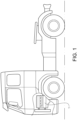
- Fig. 1 shows a vehicle in the form of a truck, or a tractor for a semitrailer. It should be noted that the vehicle can be of a variety of alternative types, e.g. it may be a car or a bus.
- the vehicle comprises a four-stroke internal combustion engine 1. It should be noted that the invention is equally applicably to a variety of engine types, such as two-stroke engines, engines adapted for cycles with six strokes, camless engines etc.
- Fig. 2 shows an operation system of the vehicle, comprising the engine 1.
- the engine comprises in this example six cylinders 301, 302 arranged in a line.
- Each cylinder 301, 302 comprise a piston connected to a rotatable crankshaft (not shown).
- the engine 1 is oriented in the vehicle such that line of cylinders is parallel with the direction of straight travel of the vehicle.
- the orientation of the engine may have another orientation in the vehicle.
- it may be a transverse engine, i.e. an engine installed such that the crankshaft of the engine is perpendicular to the direction of straight travel of the vehicle. This may be the case e.g.
- the cylinders include first cylinders 301 which are the three cylinders located forward in the vehicle direction of forward travel, and second cylinders 302 which are the three cylinders located rearward in the vehicle direction of forward travel.
- the vehicle operation system further comprises a pneumatic system 660 comprising a vehicle air brake system.
- the pneumatic system 660 may comprise another system, such as a vehicle air suspension system.
- the air brake system comprises an air compressor 673, which may be arranged to be driven by the crankshaft of the engine 1, or by any other suitable means, such as an electric motor.
- the air compressor 673 is arranged to compress air taken in from the atmosphere via a suitable air duct.
- the air compressor 673 may receive the air directly from the atmosphere, of via another air treatment device, such as a further compressor.
- the compressor 673 is connected to a compressed air storage tank 664, and is thereby arranged to deliver the compressed air to the air storage tank 664.
- a control device 665 in this example in the form of a driver's brake pedal, is arranged to actuate brake control valves 666, 667 for front and rear wheel brakes 668, 669, respectively.
- Release valves 671, 672 are arranged to release the pressure in the front and rear wheel brake circuits, respectively.
- An air guide 901 is arranged to guide air from the atmosphere to the cylinders 301, 302 of the engine 1.
- An exhaust guide 500, 501, 502 is arranged to guide exhaust gases from the cylinders to the atmosphere.
- the exhaust guide presents first and second exhaust guide branches 501, 502, each arranged to guide exhaust gases from the first and second cylinders 301, 302, respectively.
- the engine 1 comprises an exhaust valve actuation assembly 8 comprising a camshaft arrangement comprising a rotatable camshaft 801 arranged to be driven by the crankshaft.
- a cam lobe 803 is fixed to the camshaft for actuation of the exhaust valves.
- the exhaust valve actuation assembly 8 comprises for each cylinder 301, 302 a rocker arm (not shown) arranged to pivot by contact at one end with the respective cam lobe 803 to actuate the exhaust valves.
- a rocker arm (not shown) arranged to pivot by contact at one end with the respective cam lobe 803 to actuate the exhaust valves.
- the invention is equally applicable to a camless engine.
- a fuel system (not shown) is provided to inject fuel into the cylinders during cycles thereof, and the fuel injection is controllable by the control unit 21. It should be noted that the invention is equally applicable to engines in which the fuel system is arranged to inject fuel outside of the cylinders, e.g. port injected engines.
- the engine 1 comprises a turbocharger 4 comprising a turbine 401 in the exhaust guide 500.
- the turbocharger 4 also comprises a compressor 402 in the air guide 901.
- a charge air cooler 902 may be provided in the air guide 901 between the compressor 402 and the cylinders 301, 302.
- the turbine 401 and the compressor 402 are fixedly connected and rotatable, whereby the turbine 401 is arranged to be driven by gases in the exhaust guide 500, to drive the compressor 402 which is arranged to compress air in the air guide 901, as in known per se.
- the engine may be comprise a plurality of turbochargers.
- the turbine may in some implementations of the invention be one of a plurality of turbines, and/or a turbine of a turbo compound device.
- the invention is equally applicable to naturally aspirated engines.
- the first exhaust guide branch 501 is arranged to guide a gas flow from the first cylinders 301 to the turbine 401
- the second exhaust guide branch 502 is arranged to guide a gas flow from the second cylinders 302 to the turbine 401.
- the flow from the second cylinders 302 to the turbine 401 is kept separate from the flow from the first cylinders 301 to the turbine.
- the exhaust guide branches 501, 502 are joined whereby the exhaust gases are guided in an integrated portion 500 of the exhaust guide downstream of the turbine 401. It should be noted that the invention is equally applicable to engines where a single conduit of the exhaust guide is arranged to guide a gas flow from all cylinders of the engine to the turbine.
- a control unit 21 is arranged to control the operation system as described below.
- An air conduit 661 connects the pneumatic system 660 with the exhaust guide. More specifically, the air conduit 661 connects the air storage tank 664 with the second exhaust guide branch 502.
- An air valve 662 controllable by the control unit 21, is provided for selectively controlling a flow of compressed air from the air storage tank 664 into the second exhaust guide branch 502. Thereby, a junction 663 of the air conduit 661 and the second exhaust guide branch 502 is located upstream of the turbine 401.
- the air conduit 661 may connect the air storage tank 664 with the first exhaust guide branch 501 as well as the second exhaust guide branch 502. In further embodiments, the air conduit 661 may connect the air storage tank 664 with the first exhaust guide branch 501 but not with the second exhaust guide branch 502.
- the vehicle operation system also comprises downstream of the turbine 401 an exhaust after treatment system 7 for treating exhaust gases from the engine 2.
- the exhaust guide 500 is arranged to convey exhaust gases from the engine 2, as indicated by the arrow 702.
- Three exhaust after treatment devices 705, 714, 716 are located sequentially in the exhaust guide 500.
- a first of the exhaust after treatment devices is a selective catalytic reduction (SCR) catalyst 705 for selectively reducing NOx contained in the exhaust gas.
- the exhaust after treatment system 7 further comprises means 711 for supplying a reductant, e.g. urea or ammonia, into the exhaust guide 500 upstream of the SCR catalyst 705, for the NOx reduction process in the SCR catalyst.
- a reductant e.g. urea or ammonia
- a second of the exhaust after treatment devices located upstream of the SCR catalyst 705 and upstream of the reductant supply means 711, is an oxidation catalyst (DOC) 714 having the function of oxidizing carbon monoxide (CO), hydrocarbons (HC) and nitrogen monoxide (NO) contained in the exhaust gases.
- a third of the exhaust after treatment devices is a diesel particulate filter (DPF) 716, disposed downstream of the DOC 714 and upstream of the reductant supply means 711, for capturing and collecting particulate matter contained in exhaust gas. It is understood that the exhaust after treatment system 7 may be configured in other manners, and/or include other components.
- Means 221 for determining the temperature of the SCR catalyst 705 is provided in the form of an SCR temperature sensor 221 at the SCR catalyst 705, adapted to provide signals to the control unit 21.
- Means 222 for determining the temperature of the DPF 716 is provided in the form of a DPF temperature sensor 222 at the DPF 716, adapted to provide signals to the control unit 21.
- a temperature sensor may be provided at the DOC 714, or at some other suitable location in the exhaust guide 500 for determining the temperature of one or more of the exhaust after treatment devices 705, 714, 716.
- one or more temperature sensors may be provided upstream of, or between the exhaust after treatment devices.
- a numerical model may be used for determining the temperature of one or more of the exhaust after treatment devices 705, 714, 716, as is known per se.
- the engine in this embodiment comprises the following devices for providing an engine braking torque of the engine:
- An adjustable exhaust flow restriction element 601 in the form of an exhaust throttle valve is arranged in the exhaust guide 500, downstream of the turbine 401 and upstream of the exhaust after treatment system 7.
- the exhaust flow restriction element 601 is controllable by the control unit 21 via a respective exhaust flow restriction actuation assembly (not shown) comprising e.g. a stepper motor. It should be noted that alternatives for the actuation of the exhaust flow restriction element 601 are possible, such as pneumatic actuation.
- the exhaust flow restriction element is at least partly closed, so as to increase the pressure upstream of the exhaust flow restriction element 601.
- the exhaust flow restriction element 601 is arranged to provide a plurality of levels of the exhaust flow restriction depending on the adjustment by the control unit 21.
- a valve of an exhaust flow restriction element 601 may be integrated in the housing of the turbine 401.
- the turbocharger 4 may be a variable geometry turbocharger, whereby the turbocharger 4 provides, with a flow adjusting function at the turbine 401, the function of the exhaust flow restriction element 601.
- Each cam lobe 803 in the respective cylinder 301, 302 presents a relatively large main nose (not shown) for exhaust opening sequences in the cycles of the respective cylinder.
- each cam lobe 803 further presents two relatively small noses (not shown), i.e. a decompression nose and a charge nose.
- a decompression nose and a charge nose When the engine propels the vehicle, a distance is provided between on one hand the rocker arm and on the other hand the decompression nose and the charge nose, whereby the decompression nose and the charge nose do not provide any exhaust valve actuation.
- each rocker arm is in contact with the respective decompression nose and the respective charge nose.
- the selective engagement of the decompression nose and the charge nose is provided by a hydraulic piston, controlled by a hydraulic conduit system, on the rocker arm.
- the control of the hydraulic piston is provided by the control unit 21.
- Each charge nose provides a charge opening sequence, which is commenced in a second half of an intake stroke of the respective cylinder.
- the exhaust valves open for a short period and the higher pressure in the exhaust guide 500, provided by the exhaust flow restriction element 601, "charges" the cylinder.
- the decompression nose provides a decompression opening sequence, which is commenced in a compression stroke of the respective cylinder, and which serves to release air compressed during the compression stroke, whereby a push-back effect on the piston is avoided.
- the exhaust flow restriction element 601 and the decompression and charge noses of the cam lobes 803, described above, are examples of solutions for providing an engine braking torque of the engine. It is understood however that other solutions may be provided for providing an engine braking torque of the engine.
- the supply of fuel to the cylinders 301, 302 is terminated S1. Further, the exhaust flow restriction element 601 is adjusted S2 so as to restrict the flow through the exhaust guide 500. In addition, the cylinder exhaust valve actuation assembly 8 is adjusted S3 as described above so as to provide the charge opening sequence and the decompression opening sequence.
- the temperature of the DPF 716 is determined S4 by means of the DPF temperature sensor 222.
- the determined temperature is compared S5 to a threshold value. If the determined DPF temperature is above the threshold value, the air valve 662 is opened S6. Thereby the supply of air from the air compressor 664 will cool the gases flowing through the exhaust guide 500 so as to cool the exhaust after treatment devices 705, 714, 716.
- the air valve 662 While the air valve is kept open, the temperature of the DPF 716 is still determined S7, and the determined temperature is compared S9 to the threshold value. If the determined the DPF temperature is below the threshold value, the air valve 662 is closed S9.
- Fig. 4 shows a vehicle operation system according to an alternative embodiment of the invention, differing from the system described with reference to fig. 2 only regarding the following feature:
- the air conduit 661 connects the air storage tank 664 with the exhaust guide 500, whereby a junction 663 of the air conduit 661 and the exhaust guide 500 is located downstream of the turbine 401 and the exhaust flow restriction element 601, but still upstream of the exhaust after treatment system 7.
- the junction 663 of the air conduit 661 and the exhaust guide 500 is located downstream of the turbine 401 but upstream of the exhaust flow restriction element 601.
- Fig. 5 shows a vehicle operation system according to a further embodiment of the invention, differing from the system described with reference to fig. 2 only regarding the following feature:
- An exhaust flow restriction element 601 is provided in each of the first and second exhaust guide branches 501, 502.
- the air conduit 661 connects the air storage tank 664 with the second exhaust guide branch 502, downstream of the exhaust flow restriction element 601 in the second exhaust guide branch 502.
- Fig. 6 shows a vehicle operation system according to another embodiment of the invention.
- the system comprises an engine with a cylinder 301, and an exhaust guide 500 being arranged to guide a gas flow from the cylinder 301 to the atmosphere.
- the system further comprises a pneumatic system 660, and an air conduit 661 connecting the pneumatic system 660 with the exhaust guide 500 for allowing a flow of compressed air from the pneumatic system into the exhaust guide 500.
Landscapes
- Engineering & Computer Science (AREA)
- Chemical & Material Sciences (AREA)
- Mechanical Engineering (AREA)
- General Engineering & Computer Science (AREA)
- Combustion & Propulsion (AREA)
- Chemical Kinetics & Catalysis (AREA)
- Toxicology (AREA)
- Health & Medical Sciences (AREA)
- Transportation (AREA)
- Supercharger (AREA)
- Control Of Throttle Valves Provided In The Intake System Or In The Exhaust System (AREA)
- Output Control And Ontrol Of Special Type Engine (AREA)
- Exhaust Gas After Treatment (AREA)
Description
- The invention relates to a method of controlling an operation system of a vehicle, a computer program, a computer readable medium, a control unit, and a vehicle.
- The invention can be applied in heavy-duty vehicles, such as trucks and buses. Although the invention will be described with respect to a heavy-duty vehicle, the invention is not restricted to this particular vehicle, but may also be used in other vehicles such as cars.
- It may be desirable to provide, in particular in heavy-duty vehicles, a powerful engine braking function, e.g. in long downhill road stretches with heavy loads. A problem is that the engine braking process, by its conversion of braking torque to heat via air compression in the engine, may increase the temperature of exhaust after treatment devices such a filters and catalysts, to a level at which these device are damaged. As a result the engine braking power may have to be controlled so as to be decreased.
-
EP1550796 A1 suggests for controlling the temperature of exhaust gases in an engine, guiding air from an engine air intake line, downstream of a turbocharger compressor, into an exhaust line, upstream of a turbocharger turbine. However, this suggestion requires a pressure drop from the air supply line to the exhaust gas line, and this is not the case in all operational conditions. The suggestion also requires that the turbocharger can deliver the requested air flow at operational conditions where the air transport to the exhaust line is desired, and this is not always the case either. -
DE102015200462 discloses an exhaust aftertreatment system for an internal combustion engine, wherein automotive compressed air can be introduced into the exhaust system upstream of a catalyst to assist an exothermic chemical reaction on the catalyst. -
EP2360362A1 discloses a pressure accumulation system for an internal combustion engine, which can prevent the exhaust pressure from excessively increasing during engine braking. DocumentKR 20080012042 A - An object of the invention is to improve, in the operation of internal combustion engines, the control of the temperature of exhaust after treatment devices, e.g. for reducing for example NOx or soot content in exhaust gases.
- This object is reached with a method according to
claim 1. Thus, the invention provides a method of controlling an operation system for a vehicle, comprising an internal combustion engine comprising a cylinder, and an exhaust guide being arranged to guide a gas flow from the cylinder to the atmosphere, wherein the vehicle operation system further comprises a pneumatic system, and an air conduit connecting the pneumatic system with the exhaust guide for allowing a flow of compressed air from the pneumatic system into the exhaust guide. - It is understood that the cylinder is provided with a piston connected to a rotatable crankshaft for propulsion of the vehicle. Preferably the pneumatic system and the air conduit are separate from an air guide arranged to guide an air flow from the atmosphere to the cylinder. It is also understood that the engine may be provided with any suitable number of cylinders, e.g. one, four, five, six or eight, in any suitable configuration, such as an inline or a V configuration.
- The invention may serve to cool the exhaust gas stream for brief periods of time during which a risk of overheating exhaust system components would otherwise exist, limiting engine braking performance. The pneumatic system air may be used to inject comparatively cool compressed air to dilute the exhaust gas stream, lowering its temperature. Since air is usually readily available in a pneumatic system with a pressure higher than the pressure in the exhaust guide at any operational condition, e.g. at engine braking, air can be introduced to the exhaust guide to cool exhaust after treatment devices therein without any restriction caused by the operational condition of the engine. It should be noted that the invention is not only applicable to engine brake operations, but also to positive power operations, e.g. in situations with a high torque and a low engine rotational speed, or with diesel particulate filter regeneration.
- By the reliable and effective cooling capacity provided by the invention, an increase of engine braking power may be provided without the risk of overheating the exhaust after treatment system. Simulations done by the inventors indicate that the invention may increase the engine brake power by about 10% on a heavy duty vehicle diesel engine in production, where the pneumatic system utilizes an air compressor with a capacity normally available in heavy duty vehicles. The invention may be used to increase engine braking power at all engine speeds.
- Preferably, the system comprises an air valve for selectively controlling the flow of compressed air from the pneumatic system into the exhaust guide. Thereby, the provision of the pneumatic system air may be effectively controlled to be adapted to the requirements of the engine operation.
- An exhaust after treatment device, e.g. a catalytic converter or a particulate filter, may be located in the exhaust guide, downstream of a junction of the air conduit and the exhaust guide. Thereby, the cooling effect of the pneumatic air from the air conduit may the effectively secured. It is understood that the junction of the air conduit and the exhaust guide is at a location at which the compressed air is allowed into the exhaust guide, or where the air conduit releases air into the exhaust guide.
- Preferably, the system comprises means for determining the temperature of the exhaust after treatment device. Thereby, the provision of the pneumatic system air may be effectively controlled to be adapted to the cooling requirements of the exhaust after treatment device.
- The pneumatic system may comprise, or be, a vehicle air brake system. In some embodiments, the pneumatic system may comprise, or be, a vehicle air suspension system. Since in heavy duty vehicles such systems are normally provided with relatively powerful air compressors, the supply of air to the exhaust guide may be secured for the needs of the engine operation.
- Preferably, where a turbine is located in the exhaust guide, a junction of the air conduit and the exhaust guide is located upstream of the turbine. Where the engine comprises an air guide arranged to guide an air flow from the atmosphere to the cylinder, the turbine may form a part of a turbocharger of the engine, comprising a compressor arranged to compress air in the air guide, the turbine being arranged to drive the compressor. It is understood that thereby the turbine is normally rotationally rigidly connected to the compressor for converting energy of the exhaust gas flow to a rotational movement of the compressor. By providing the junction of the air conduit and the exhaust guide upstream of the turbine, the air introduced from the pneumatic system may be used to increase the work of the turbocharger, which in engine brake modes may increase the braking work due to an increased turbo charger rotational speed giving an increased air mass flow and an increased boost pressure. Also, the injected air may be cooled as it passes through the turbine.
- In some embodiments, the junction of the air conduit and the exhaust guide may be located downstream of the turbine. Also in such embodiments, engine braking work may be increased due to the capacity to securely avoid overheating of an exhaust treatment system by the air introduction.
- It should be noted that the turbine may in some implementations of the invention be one of a plurality of turbines, e.g. where a turbocharger comprising the turbine is a two-step turbocharger or a sequential turbocharger. Further, the invention may be implemented where the engine comprises a plurality of cylinders, the exhaust guide presents two exhaust guide branches, each arranged to guide exhaust gases from a respective subgroup of the cylinders, and a turbocharger of the engine presents a bi-turbo configuration. In some implementations of the invention, a turbine of a turbo compound device is located in the exhaust guide, a junction of the air conduit and the exhaust guide being located upstream of the turbine. It should be noted that the invention is also applicable to naturally aspirated engines.
- An adjustable exhaust flow restriction element is arranged to restrict the flow through the exhaust guide. Preferably, a junction of the air conduit and the exhaust guide is located upstream of the exhaust flow restriction element. As exemplified below, the system may comprise further or alternative devices for providing an engine braking torque.
- A turbine may as suggested be located in the exhaust guide. In addition, an adjustable exhaust flow restriction element may be arranged to restrict the flow through the exhaust guide, the exhaust flow restriction element being located downstream of the turbine. Where the engine comprises an air guide arranged to guide an air flow from the atmosphere to the cylinder, the system may comprise a turbocharger comprising a compressor arranged to compress air in the air guide, and the turbine which is arranged to drive the compressor. In such embodiments, the possibility to introduce pressurized air from the pneumatic system is particularly advantageous. The reason is that during engine braking, the pressure increase caused by the exhaust flow restriction element reduces or eliminates the work of the turbocharger, so that the air guide pressure is relatively low, whereby said known solution to guide air from the air guide to the exhaust guide to cool exhaust after treatment devices would not work. However, the possibility provided by the invention to introduce pressurized air from the pneumatic system will allow cooling of exhaust after treatment devices even if the turbocharger work is low or non-existent. Also, as stated where the junction of the air conduit and the exhaust guide is located upstream of the turbine, the air introduced from the pneumatic system may be used to increase the work of the turbocharger, which in engine brake modes may increase the braking work due to an increased turbo charger rotational speed giving an increased air mass flow and an increased boost pressure.
- In some implementations of the invention, a turbine of a turbo compound device is located in the exhaust guide, and an adjustable exhaust flow restriction element is arranged to restrict the flow through the exhaust guide, the exhaust flow restriction element being located downstream of the turbine.
- As stated above, the object is reached with a method of controlling an operation system of a vehicle, comprising an internal combustion engine for propulsion of the vehicle, the engine comprising a cylinder arranged to compress air from the atmosphere received via an air guide, the engine further comprising an exhaust guide arranged to guide a gas flow from the cylinder to the atmosphere,
- the method comprising controlling the engine to provide a braking torque,
- and controlling, during the control of the engine to provide a braking torque, an air valve to allow a flow of compressed air from a compressed air source other than the cylinder via an air conduit into the exhaust guide.
- Thereby, an exhaust gas after treatment system located in the exhaust guide may be cooled by the air from a compressed air source, to avoid the exhaust gas after treatment system being overheated during the engine braking operation. The compressed air source is preferably a pneumatic system of the operation system; as suggested above, thereby, the cooling capacity may be secured independently of the operational condition of the engine, and the engine braking power may be increased.
- The method comprises determining a temperature of an exhaust after treatment device located in the exhaust guide, wherein controlling the air valve comprises controlling the air valve in dependence on the determined exhaust after treatment device temperature. As suggested, thereby the provision of the compressed air source air may be effectively controlled to be adapted to the cooling requirements of an exhaust after treatment device in the exhaust guide.
- Controlling the engine to provide a braking torque may comprise controlling an adjustable exhaust flow restriction element so as to restrict the flow through the exhaust guide. Such a control may increase the exhaust back pressure, thus increasing the engine braking torque.
- The object is also reached with a computer program according to claim 4, a computer readable medium according to
claim 5, a control unit according to claim 6, and a vehicle according to claim 7. - Further advantages and advantageous features of the invention are disclosed in the following description and in the dependent claims.
- With reference to the appended drawings, below follows a more detailed description of embodiments of the invention cited as examples.
- In the drawings:
-
Fig. 1 is a side view of a vehicle in the form of a truck. -
Fig. 2 is a schematic drawing of an operation system in the vehicle infig. 1 , comprising an internal combustion engine. -
Fig. 3 is a block diagram depicting steps in a method of controlling the system infig. 2 . -
Fig. 4 is a schematic drawing of a vehicle operation system according to an alternative embodiment of the invention. -
Fig. 5 is a schematic drawing of a vehicle operation system according to another embodiment of the invention. -
Fig. 6 is a schematic drawing of a vehicle operation system according to yet another embodiment of the invention. -
Fig. 1 shows a vehicle in the form of a truck, or a tractor for a semitrailer. It should be noted that the vehicle can be of a variety of alternative types, e.g. it may be a car or a bus. The vehicle comprises a four-strokeinternal combustion engine 1. It should be noted that the invention is equally applicably to a variety of engine types, such as two-stroke engines, engines adapted for cycles with six strokes, camless engines etc. -
Fig. 2 shows an operation system of the vehicle, comprising theengine 1. The engine comprises in this example sixcylinders cylinder engine 1 is oriented in the vehicle such that line of cylinders is parallel with the direction of straight travel of the vehicle. It should be noted however that in alternative embodiments the orientation of the engine may have another orientation in the vehicle. For example it may be a transverse engine, i.e. an engine installed such that the crankshaft of the engine is perpendicular to the direction of straight travel of the vehicle. This may be the case e.g. in a bus, where the engine may be a transverse engine mounted in the rear of the bus. The cylinders includefirst cylinders 301 which are the three cylinders located forward in the vehicle direction of forward travel, andsecond cylinders 302 which are the three cylinders located rearward in the vehicle direction of forward travel. - The vehicle operation system further comprises a
pneumatic system 660 comprising a vehicle air brake system. Alternatively or in addition, thepneumatic system 660 may comprise another system, such as a vehicle air suspension system. The air brake system comprises anair compressor 673, which may be arranged to be driven by the crankshaft of theengine 1, or by any other suitable means, such as an electric motor. Theair compressor 673 is arranged to compress air taken in from the atmosphere via a suitable air duct. Theair compressor 673 may receive the air directly from the atmosphere, of via another air treatment device, such as a further compressor. Thecompressor 673 is connected to a compressedair storage tank 664, and is thereby arranged to deliver the compressed air to theair storage tank 664. Acontrol device 665, in this example in the form of a driver's brake pedal, is arranged to actuatebrake control valves rear wheel brakes Release valves - An
air guide 901 is arranged to guide air from the atmosphere to thecylinders engine 1. Anexhaust guide exhaust guide branches second cylinders - At each of the
cylinders air guide 901 to therespective cylinder respective cylinder exhaust guide branch engine 1 comprises an exhaustvalve actuation assembly 8 comprising a camshaft arrangement comprising arotatable camshaft 801 arranged to be driven by the crankshaft. At eachcylinder 301, 302 acam lobe 803 is fixed to the camshaft for actuation of the exhaust valves. The exhaustvalve actuation assembly 8 comprises for eachcylinder 301, 302 a rocker arm (not shown) arranged to pivot by contact at one end with therespective cam lobe 803 to actuate the exhaust valves. As suggested, the invention is equally applicable to a camless engine. - Also, a fuel system (not shown) is provided to inject fuel into the cylinders during cycles thereof, and the fuel injection is controllable by the
control unit 21. It should be noted that the invention is equally applicable to engines in which the fuel system is arranged to inject fuel outside of the cylinders, e.g. port injected engines. - The
engine 1 comprises a turbocharger 4 comprising aturbine 401 in theexhaust guide 500. - The turbocharger 4 also comprises a
compressor 402 in theair guide 901. Acharge air cooler 902 may be provided in theair guide 901 between thecompressor 402 and thecylinders turbine 401 and thecompressor 402 are fixedly connected and rotatable, whereby theturbine 401 is arranged to be driven by gases in theexhaust guide 500, to drive thecompressor 402 which is arranged to compress air in theair guide 901, as in known per se. - In some implementations of the invention, the engine may be comprise a plurality of turbochargers. As suggested, the turbine may in some implementations of the invention be one of a plurality of turbines, and/or a turbine of a turbo compound device. As also suggested the invention is equally applicable to naturally aspirated engines.
- The first
exhaust guide branch 501 is arranged to guide a gas flow from thefirst cylinders 301 to theturbine 401, and the secondexhaust guide branch 502 is arranged to guide a gas flow from thesecond cylinders 302 to theturbine 401. Thereby, the flow from thesecond cylinders 302 to theturbine 401 is kept separate from the flow from thefirst cylinders 301 to the turbine. At theturbine 401 theexhaust guide branches integrated portion 500 of the exhaust guide downstream of theturbine 401. It should be noted that the invention is equally applicable to engines where a single conduit of the exhaust guide is arranged to guide a gas flow from all cylinders of the engine to the turbine. - A
control unit 21 is arranged to control the operation system as described below. - An
air conduit 661 connects thepneumatic system 660 with the exhaust guide. More specifically, theair conduit 661 connects theair storage tank 664 with the secondexhaust guide branch 502. Anair valve 662, controllable by thecontrol unit 21, is provided for selectively controlling a flow of compressed air from theair storage tank 664 into the secondexhaust guide branch 502. Thereby, ajunction 663 of theair conduit 661 and the secondexhaust guide branch 502 is located upstream of theturbine 401. - In alternative embodiments, the
air conduit 661, or a pair of air conduits, may connect theair storage tank 664 with the firstexhaust guide branch 501 as well as the secondexhaust guide branch 502. In further embodiments, theair conduit 661 may connect theair storage tank 664 with the firstexhaust guide branch 501 but not with the secondexhaust guide branch 502. - The vehicle operation system also comprises downstream of the
turbine 401 an exhaust after treatment system 7 for treating exhaust gases from theengine 2. Theexhaust guide 500 is arranged to convey exhaust gases from theengine 2, as indicated by thearrow 702. Three exhaust aftertreatment devices exhaust guide 500. A first of the exhaust after treatment devices is a selective catalytic reduction (SCR)catalyst 705 for selectively reducing NOx contained in the exhaust gas. The exhaust after treatment system 7 further comprisesmeans 711 for supplying a reductant, e.g. urea or ammonia, into theexhaust guide 500 upstream of theSCR catalyst 705, for the NOx reduction process in the SCR catalyst. A second of the exhaust after treatment devices, located upstream of theSCR catalyst 705 and upstream of the reductant supply means 711, is an oxidation catalyst (DOC) 714 having the function of oxidizing carbon monoxide (CO), hydrocarbons (HC) and nitrogen monoxide (NO) contained in the exhaust gases. A third of the exhaust after treatment devices is a diesel particulate filter (DPF) 716, disposed downstream of theDOC 714 and upstream of the reductant supply means 711, for capturing and collecting particulate matter contained in exhaust gas. It is understood that the exhaust after treatment system 7 may be configured in other manners, and/or include other components. -
Means 221 for determining the temperature of theSCR catalyst 705 is provided in the form of anSCR temperature sensor 221 at theSCR catalyst 705, adapted to provide signals to thecontrol unit 21.Means 222 for determining the temperature of theDPF 716 is provided in the form of aDPF temperature sensor 222 at theDPF 716, adapted to provide signals to thecontrol unit 21. Alternatively or additionally such a temperature sensor may be provided at theDOC 714, or at some other suitable location in theexhaust guide 500 for determining the temperature of one or more of the exhaust aftertreatment devices treatment devices - The engine in this embodiment comprises the following devices for providing an engine braking torque of the engine:
An adjustable exhaustflow restriction element 601 in the form of an exhaust throttle valve is arranged in theexhaust guide 500, downstream of theturbine 401 and upstream of the exhaust after treatment system 7. The exhaustflow restriction element 601 is controllable by thecontrol unit 21 via a respective exhaust flow restriction actuation assembly (not shown) comprising e.g. a stepper motor. It should be noted that alternatives for the actuation of the exhaustflow restriction element 601 are possible, such as pneumatic actuation. During engine braking, the exhaust flow restriction element is at least partly closed, so as to increase the pressure upstream of the exhaustflow restriction element 601. The exhaustflow restriction element 601 is arranged to provide a plurality of levels of the exhaust flow restriction depending on the adjustment by thecontrol unit 21. - In alternative embodiments, a valve of an exhaust
flow restriction element 601 may be integrated in the housing of theturbine 401. In further embodiments, the turbocharger 4 may be a variable geometry turbocharger, whereby the turbocharger 4 provides, with a flow adjusting function at theturbine 401, the function of the exhaustflow restriction element 601. - Each
cam lobe 803 in therespective cylinder US5146890A , incorporated herein by reference, eachcam lobe 803 further presents two relatively small noses (not shown), i.e. a decompression nose and a charge nose. When the engine propels the vehicle, a distance is provided between on one hand the rocker arm and on the other hand the decompression nose and the charge nose, whereby the decompression nose and the charge nose do not provide any exhaust valve actuation. During engine braking, each rocker arm is in contact with the respective decompression nose and the respective charge nose. The selective engagement of the decompression nose and the charge nose is provided by a hydraulic piston, controlled by a hydraulic conduit system, on the rocker arm. The control of the hydraulic piston is provided by thecontrol unit 21. - Each charge nose provides a charge opening sequence, which is commenced in a second half of an intake stroke of the respective cylinder. Thereby, when the piston is at its bottom dead centre and the compression stroke is about to start, the exhaust valves open for a short period and the higher pressure in the
exhaust guide 500, provided by the exhaustflow restriction element 601, "charges" the cylinder. As a result of this, the braking effect on the piston during the compression stroke will be increased. Further during engine braking, the decompression nose provides a decompression opening sequence, which is commenced in a compression stroke of the respective cylinder, and which serves to release air compressed during the compression stroke, whereby a push-back effect on the piston is avoided. - The exhaust
flow restriction element 601 and the decompression and charge noses of thecam lobes 803, described above, are examples of solutions for providing an engine braking torque of the engine. It is understood however that other solutions may be provided for providing an engine braking torque of the engine. - With reference to
fig. 3 a method of controlling the vehicle operation system to provide an engine braking torque will be described. - For providing engine braking, the supply of fuel to the
cylinders flow restriction element 601 is adjusted S2 so as to restrict the flow through theexhaust guide 500. In addition, the cylinder exhaustvalve actuation assembly 8 is adjusted S3 as described above so as to provide the charge opening sequence and the decompression opening sequence. - During engine braking, the temperature of the
DPF 716 is determined S4 by means of theDPF temperature sensor 222. The determined temperature is compared S5 to a threshold value. If the determined DPF temperature is above the threshold value, theair valve 662 is opened S6. Thereby the supply of air from theair compressor 664 will cool the gases flowing through theexhaust guide 500 so as to cool the exhaust aftertreatment devices - While the air valve is kept open, the temperature of the
DPF 716 is still determined S7, and the determined temperature is compared S9 to the threshold value. If the determined the DPF temperature is below the threshold value, theair valve 662 is closed S9. -
Fig. 4 shows a vehicle operation system according to an alternative embodiment of the invention, differing from the system described with reference tofig. 2 only regarding the following feature: Theair conduit 661 connects theair storage tank 664 with theexhaust guide 500, whereby ajunction 663 of theair conduit 661 and theexhaust guide 500 is located downstream of theturbine 401 and the exhaustflow restriction element 601, but still upstream of the exhaust after treatment system 7. In alternative embodiments, thejunction 663 of theair conduit 661 and theexhaust guide 500 is located downstream of theturbine 401 but upstream of the exhaustflow restriction element 601. -
Fig. 5 shows a vehicle operation system according to a further embodiment of the invention, differing from the system described with reference tofig. 2 only regarding the following feature: An exhaustflow restriction element 601 is provided in each of the first and secondexhaust guide branches air conduit 661 connects theair storage tank 664 with the secondexhaust guide branch 502, downstream of the exhaustflow restriction element 601 in the secondexhaust guide branch 502. -
Fig. 6 shows a vehicle operation system according to another embodiment of the invention. The system comprises an engine with acylinder 301, and anexhaust guide 500 being arranged to guide a gas flow from thecylinder 301 to the atmosphere. The system further comprises apneumatic system 660, and anair conduit 661 connecting thepneumatic system 660 with theexhaust guide 500 for allowing a flow of compressed air from the pneumatic system into theexhaust guide 500. - It is to be understood that the present invention is not limited to the embodiments described above and illustrated in the drawings; rather, the skilled person will recognize that many changes and modifications may be made within the scope of the appended claims.
Claims (7)
- A method of controlling an operation system of a vehicle, comprising an internal combustion engine (1) for propulsion of the vehicle, the engine comprising a cylinder (301, 302) arranged to compress air from the atmosphere received via an air guide (901), the engine further comprising an exhaust guide (500, 501, 502) arranged to guide a gas flow from the cylinder (301, 302) to the atmosphere,- the method comprising controlling (S1, S2, S3) the engine to provide a braking torque,- controlling (S6), during the control of the engine to provide a braking torque, an air valve (662) to allow a flow of compressed air from a compressed air source (660) other than the cylinder (301, 302) via an air conduit (661) into the exhaust guide (500, 501, 502),- and controlling the engine to provide a braking torque comprises controlling (S2) an adjustable exhaust flow restriction element (601) so as to restrict the flow through the exhaust guide (500, 501, 502).characterized by determining (S4) a temperature of an exhaust after treatment device (705, 714, 716) located in the exhaust guide (500, 501, 502), wherein controlling (S4) the air valve (662) comprises controlling the air valve (662) in dependence on the determined exhaust after treatment device temperature.
- A method according to claim 1, characterized in that the compressed air source is a pneumatic system (660) of the operation system.
- A method of according to any one of the claims 1-2, characterized in that the compressed air source is a pneumatic system of the operation system, wherein the pneumatic system comprises a vehicle air brake system, and/or a vehicle air suspension system, or the pneumatic system is a vehicle air brake system or a vehicle air suspension system.
- A computer program comprising program code means for performing the steps of any of claims 1-3 when said program is run on a computer.
- A computer readable medium carrying a computer program comprising program code means for performing the steps of any of claims 1-3 when said program product is run on a computer.
- A control unit (21) configured to perform the steps of the method according to any of claims 1-3.
- A vehicle comprising a control unit according to claim 6.
Applications Claiming Priority (1)
| Application Number | Priority Date | Filing Date | Title |
|---|---|---|---|
| PCT/EP2017/056219 WO2018166597A1 (en) | 2017-03-16 | 2017-03-16 | A system for improved engine braking |
Publications (3)
| Publication Number | Publication Date |
|---|---|
| EP3596319A1 EP3596319A1 (en) | 2020-01-22 |
| EP3596319C0 EP3596319C0 (en) | 2024-03-27 |
| EP3596319B1 true EP3596319B1 (en) | 2024-03-27 |
Family
ID=58347367
Family Applications (1)
| Application Number | Title | Priority Date | Filing Date |
|---|---|---|---|
| EP17711156.4A Active EP3596319B1 (en) | 2017-03-16 | 2017-03-16 | A system for improved engine braking |
Country Status (4)
| Country | Link |
|---|---|
| US (1) | US11220963B2 (en) |
| EP (1) | EP3596319B1 (en) |
| CN (1) | CN110431290B (en) |
| WO (1) | WO2018166597A1 (en) |
Citations (2)
| Publication number | Priority date | Publication date | Assignee | Title |
|---|---|---|---|---|
| KR20080012042A (en) * | 2006-08-02 | 2008-02-11 | 현대자동차주식회사 | Automotive exhaust brake performance enhancement system |
| EP2360362B1 (en) * | 2008-12-11 | 2015-03-25 | Toyota Jidosha Kabushiki Kaisha | Pressure accumulation system for internal combustion engine |
Family Cites Families (18)
| Publication number | Priority date | Publication date | Assignee | Title |
|---|---|---|---|---|
| SE466320B (en) | 1989-02-15 | 1992-01-27 | Volvo Ab | PROCEDURES AND DEVICE FOR ENGINE BRAKING WITH A FIREWORKS ENGINE |
| CN1310290A (en) | 2000-12-01 | 2001-08-29 | 莫嘉林 | Engine exhaust treating method |
| DE10135303A1 (en) | 2001-07-19 | 2003-02-13 | Bosch Gmbh Robert | Method and device for exhaust gas aftertreatment in internal combustion engines |
| US6880572B2 (en) * | 2002-04-15 | 2005-04-19 | Jenara Enterprises Ltd. | Exhaust gas control valve, apparatus and method of controlling exhaust gas flow |
| ITMI20032606A1 (en) | 2003-12-29 | 2005-06-30 | Iveco Spa | METHOD FOR CHECKING TEMPERATURE OF EXHAUST GAS IN MOTOR SYSTEM AND MOTOR SYSTEM |
| US7050900B2 (en) * | 2004-02-17 | 2006-05-23 | Miller Kenneth C | Dynamically reconfigurable internal combustion engine |
| DE102004047975A1 (en) * | 2004-10-01 | 2006-04-13 | Knorr-Bremse Ag | Method and device for increasing a torque of a reciprocating internal combustion engine, in particular a diesel engine |
| US7244003B2 (en) * | 2004-12-20 | 2007-07-17 | International Truck Intellectual Property Company, Llc | Vehicle onboard brake pad/lining wear estimators with temperature estimations |
| US7530404B2 (en) * | 2006-07-20 | 2009-05-12 | Hme, Inc. | Compressed fluid system and related method |
| DE102007027968A1 (en) * | 2007-06-19 | 2009-01-02 | Knorr-Bremse Systeme für Nutzfahrzeuge GmbH | Method and device for increasing the engine braking power of a reciprocating internal combustion engine of a vehicle, in particular a diesel engine |
| DE102008008723B4 (en) * | 2008-02-12 | 2013-07-11 | Knorr-Bremse Systeme für Nutzfahrzeuge GmbH | Method and device for generating compressed air and for blowing the same in an internal combustion engine |
| GB2457917A (en) * | 2008-02-28 | 2009-09-02 | Univ Brunel | I.c engine air hybrid vehicle |
| US20110289914A1 (en) | 2010-05-28 | 2011-12-01 | Caterpillar Inc. | Upstream egr restriction |
| US20130276443A1 (en) | 2012-04-19 | 2013-10-24 | GM Global Technology Operations LLC | System and method for controlling an exhaust-braking engine maneuver |
| US20140261310A1 (en) * | 2013-03-15 | 2014-09-18 | Caterpillar Inc. | System and method to optimize engine braking power |
| KR20160066572A (en) | 2014-12-02 | 2016-06-13 | 현대자동차주식회사 | Thermoelectric power generation system for vehicle |
| DE102015200462A1 (en) | 2015-01-14 | 2016-07-14 | Robert Bosch Gmbh | aftertreatment system |
| EP3408517B1 (en) * | 2016-01-29 | 2020-01-08 | Volvo Truck Corporation | An internal combustion engine and a method comprising control of the engine to provide a braking torque |
-
2017
- 2017-03-16 CN CN201780088303.5A patent/CN110431290B/en not_active Expired - Fee Related
- 2017-03-16 EP EP17711156.4A patent/EP3596319B1/en active Active
- 2017-03-16 WO PCT/EP2017/056219 patent/WO2018166597A1/en not_active Ceased
- 2017-03-16 US US16/493,515 patent/US11220963B2/en active Active
Patent Citations (2)
| Publication number | Priority date | Publication date | Assignee | Title |
|---|---|---|---|---|
| KR20080012042A (en) * | 2006-08-02 | 2008-02-11 | 현대자동차주식회사 | Automotive exhaust brake performance enhancement system |
| EP2360362B1 (en) * | 2008-12-11 | 2015-03-25 | Toyota Jidosha Kabushiki Kaisha | Pressure accumulation system for internal combustion engine |
Also Published As
| Publication number | Publication date |
|---|---|
| CN110431290B (en) | 2022-04-01 |
| EP3596319C0 (en) | 2024-03-27 |
| US20210131358A1 (en) | 2021-05-06 |
| EP3596319A1 (en) | 2020-01-22 |
| WO2018166597A1 (en) | 2018-09-20 |
| US11220963B2 (en) | 2022-01-11 |
| CN110431290A (en) | 2019-11-08 |
Similar Documents
| Publication | Publication Date | Title |
|---|---|---|
| KR101826571B1 (en) | Engine system | |
| US9441532B2 (en) | Engine assembly with turbine generator control | |
| CN102220895A (en) | Closely-coupled exhaust aftertreatment system for a turbocharged engine | |
| EP3559431B1 (en) | A method for controlling an internal combustion engine | |
| EP1561015B1 (en) | Method for cleaning a particle filter and a vehicle for utilizing said method | |
| EP1664497B1 (en) | Piston-type internal combustion engine | |
| EP1929143B1 (en) | Method for internal combustion engine with exhaust recirculation | |
| JP4760726B2 (en) | vehicle | |
| CN108979795B (en) | System and method for controlling exhaust flow through dual aftertreatment devices | |
| EP2131022B1 (en) | Thermal management of the after treatment system | |
| US20130000297A1 (en) | Emissions reduction system | |
| US11698019B2 (en) | Exhaust gas aftertreatment system | |
| EP3596319B1 (en) | A system for improved engine braking | |
| CN100432384C (en) | piston internal combustion engine | |
| US10830191B1 (en) | Temperature management of an aftertreatment system during compression braking | |
| US20190316529A1 (en) | Method and system for controlling an internal combustion engine | |
| CN107013346A (en) | The method for operating the automotive system for providing power for vehicle |
Legal Events
| Date | Code | Title | Description |
|---|---|---|---|
| STAA | Information on the status of an ep patent application or granted ep patent |
Free format text: STATUS: UNKNOWN |
|
| STAA | Information on the status of an ep patent application or granted ep patent |
Free format text: STATUS: THE INTERNATIONAL PUBLICATION HAS BEEN MADE |
|
| PUAI | Public reference made under article 153(3) epc to a published international application that has entered the european phase |
Free format text: ORIGINAL CODE: 0009012 |
|
| STAA | Information on the status of an ep patent application or granted ep patent |
Free format text: STATUS: REQUEST FOR EXAMINATION WAS MADE |
|
| 17P | Request for examination filed |
Effective date: 20191016 |
|
| AK | Designated contracting states |
Kind code of ref document: A1 Designated state(s): AL AT BE BG CH CY CZ DE DK EE ES FI FR GB GR HR HU IE IS IT LI LT LU LV MC MK MT NL NO PL PT RO RS SE SI SK SM TR |
|
| AX | Request for extension of the european patent |
Extension state: BA ME |
|
| DAV | Request for validation of the european patent (deleted) | ||
| DAX | Request for extension of the european patent (deleted) | ||
| STAA | Information on the status of an ep patent application or granted ep patent |
Free format text: STATUS: EXAMINATION IS IN PROGRESS |
|
| 17Q | First examination report despatched |
Effective date: 20200820 |
|
| GRAP | Despatch of communication of intention to grant a patent |
Free format text: ORIGINAL CODE: EPIDOSNIGR1 |
|
| STAA | Information on the status of an ep patent application or granted ep patent |
Free format text: STATUS: GRANT OF PATENT IS INTENDED |
|
| INTG | Intention to grant announced |
Effective date: 20210517 |
|
| GRAJ | Information related to disapproval of communication of intention to grant by the applicant or resumption of examination proceedings by the epo deleted |
Free format text: ORIGINAL CODE: EPIDOSDIGR1 |
|
| STAA | Information on the status of an ep patent application or granted ep patent |
Free format text: STATUS: EXAMINATION IS IN PROGRESS |
|
| INTC | Intention to grant announced (deleted) | ||
| GRAP | Despatch of communication of intention to grant a patent |
Free format text: ORIGINAL CODE: EPIDOSNIGR1 |
|
| STAA | Information on the status of an ep patent application or granted ep patent |
Free format text: STATUS: GRANT OF PATENT IS INTENDED |
|
| INTG | Intention to grant announced |
Effective date: 20231005 |
|
| GRAS | Grant fee paid |
Free format text: ORIGINAL CODE: EPIDOSNIGR3 |
|
| GRAA | (expected) grant |
Free format text: ORIGINAL CODE: 0009210 |
|
| STAA | Information on the status of an ep patent application or granted ep patent |
Free format text: STATUS: THE PATENT HAS BEEN GRANTED |
|
| AK | Designated contracting states |
Kind code of ref document: B1 Designated state(s): AL AT BE BG CH CY CZ DE DK EE ES FI FR GB GR HR HU IE IS IT LI LT LU LV MC MK MT NL NO PL PT RO RS SE SI SK SM TR |
|
| REG | Reference to a national code |
Ref country code: GB Ref legal event code: FG4D |
|
| REG | Reference to a national code |
Ref country code: CH Ref legal event code: EP |
|
| REG | Reference to a national code |
Ref country code: DE Ref legal event code: R096 Ref document number: 602017080351 Country of ref document: DE |
|
| REG | Reference to a national code |
Ref country code: IE Ref legal event code: FG4D |
|
| U01 | Request for unitary effect filed |
Effective date: 20240418 |
|
| U07 | Unitary effect registered |
Designated state(s): AT BE BG DE DK EE FI FR IT LT LU LV MT NL PT SE SI Effective date: 20240425 |
|
| PG25 | Lapsed in a contracting state [announced via postgrant information from national office to epo] |
Ref country code: GR Free format text: LAPSE BECAUSE OF FAILURE TO SUBMIT A TRANSLATION OF THE DESCRIPTION OR TO PAY THE FEE WITHIN THE PRESCRIBED TIME-LIMIT Effective date: 20240628 |
|
| PG25 | Lapsed in a contracting state [announced via postgrant information from national office to epo] |
Ref country code: RS Free format text: LAPSE BECAUSE OF FAILURE TO SUBMIT A TRANSLATION OF THE DESCRIPTION OR TO PAY THE FEE WITHIN THE PRESCRIBED TIME-LIMIT Effective date: 20240627 Ref country code: HR Free format text: LAPSE BECAUSE OF FAILURE TO SUBMIT A TRANSLATION OF THE DESCRIPTION OR TO PAY THE FEE WITHIN THE PRESCRIBED TIME-LIMIT Effective date: 20240327 |
|
| PG25 | Lapsed in a contracting state [announced via postgrant information from national office to epo] |
Ref country code: RS Free format text: LAPSE BECAUSE OF FAILURE TO SUBMIT A TRANSLATION OF THE DESCRIPTION OR TO PAY THE FEE WITHIN THE PRESCRIBED TIME-LIMIT Effective date: 20240627 Ref country code: NO Free format text: LAPSE BECAUSE OF FAILURE TO SUBMIT A TRANSLATION OF THE DESCRIPTION OR TO PAY THE FEE WITHIN THE PRESCRIBED TIME-LIMIT Effective date: 20240627 Ref country code: HR Free format text: LAPSE BECAUSE OF FAILURE TO SUBMIT A TRANSLATION OF THE DESCRIPTION OR TO PAY THE FEE WITHIN THE PRESCRIBED TIME-LIMIT Effective date: 20240327 Ref country code: GR Free format text: LAPSE BECAUSE OF FAILURE TO SUBMIT A TRANSLATION OF THE DESCRIPTION OR TO PAY THE FEE WITHIN THE PRESCRIBED TIME-LIMIT Effective date: 20240628 |
|
| PG25 | Lapsed in a contracting state [announced via postgrant information from national office to epo] |
Ref country code: IS Free format text: LAPSE BECAUSE OF FAILURE TO SUBMIT A TRANSLATION OF THE DESCRIPTION OR TO PAY THE FEE WITHIN THE PRESCRIBED TIME-LIMIT Effective date: 20240727 |
|
| PG25 | Lapsed in a contracting state [announced via postgrant information from national office to epo] |
Ref country code: SM Free format text: LAPSE BECAUSE OF FAILURE TO SUBMIT A TRANSLATION OF THE DESCRIPTION OR TO PAY THE FEE WITHIN THE PRESCRIBED TIME-LIMIT Effective date: 20240327 |
|
| PG25 | Lapsed in a contracting state [announced via postgrant information from national office to epo] |
Ref country code: ES Free format text: LAPSE BECAUSE OF FAILURE TO SUBMIT A TRANSLATION OF THE DESCRIPTION OR TO PAY THE FEE WITHIN THE PRESCRIBED TIME-LIMIT Effective date: 20240327 |
|
| PG25 | Lapsed in a contracting state [announced via postgrant information from national office to epo] |
Ref country code: CZ Free format text: LAPSE BECAUSE OF FAILURE TO SUBMIT A TRANSLATION OF THE DESCRIPTION OR TO PAY THE FEE WITHIN THE PRESCRIBED TIME-LIMIT Effective date: 20240327 |
|
| PG25 | Lapsed in a contracting state [announced via postgrant information from national office to epo] |
Ref country code: PL Free format text: LAPSE BECAUSE OF FAILURE TO SUBMIT A TRANSLATION OF THE DESCRIPTION OR TO PAY THE FEE WITHIN THE PRESCRIBED TIME-LIMIT Effective date: 20240327 |
|
| PG25 | Lapsed in a contracting state [announced via postgrant information from national office to epo] |
Ref country code: SK Free format text: LAPSE BECAUSE OF FAILURE TO SUBMIT A TRANSLATION OF THE DESCRIPTION OR TO PAY THE FEE WITHIN THE PRESCRIBED TIME-LIMIT Effective date: 20240327 |
|
| PG25 | Lapsed in a contracting state [announced via postgrant information from national office to epo] |
Ref country code: SM Free format text: LAPSE BECAUSE OF FAILURE TO SUBMIT A TRANSLATION OF THE DESCRIPTION OR TO PAY THE FEE WITHIN THE PRESCRIBED TIME-LIMIT Effective date: 20240327 Ref country code: SK Free format text: LAPSE BECAUSE OF FAILURE TO SUBMIT A TRANSLATION OF THE DESCRIPTION OR TO PAY THE FEE WITHIN THE PRESCRIBED TIME-LIMIT Effective date: 20240327 Ref country code: RO Free format text: LAPSE BECAUSE OF FAILURE TO SUBMIT A TRANSLATION OF THE DESCRIPTION OR TO PAY THE FEE WITHIN THE PRESCRIBED TIME-LIMIT Effective date: 20240327 Ref country code: PL Free format text: LAPSE BECAUSE OF FAILURE TO SUBMIT A TRANSLATION OF THE DESCRIPTION OR TO PAY THE FEE WITHIN THE PRESCRIBED TIME-LIMIT Effective date: 20240327 Ref country code: IS Free format text: LAPSE BECAUSE OF FAILURE TO SUBMIT A TRANSLATION OF THE DESCRIPTION OR TO PAY THE FEE WITHIN THE PRESCRIBED TIME-LIMIT Effective date: 20240727 Ref country code: ES Free format text: LAPSE BECAUSE OF FAILURE TO SUBMIT A TRANSLATION OF THE DESCRIPTION OR TO PAY THE FEE WITHIN THE PRESCRIBED TIME-LIMIT Effective date: 20240327 Ref country code: CZ Free format text: LAPSE BECAUSE OF FAILURE TO SUBMIT A TRANSLATION OF THE DESCRIPTION OR TO PAY THE FEE WITHIN THE PRESCRIBED TIME-LIMIT Effective date: 20240327 |
|
| U1N | Appointed representative for the unitary patent procedure changed after the registration of the unitary effect |
Representative=s name: LAVOIX; DE |
|
| REG | Reference to a national code |
Ref country code: DE Ref legal event code: R097 Ref document number: 602017080351 Country of ref document: DE |
|
| PLBE | No opposition filed within time limit |
Free format text: ORIGINAL CODE: 0009261 |
|
| STAA | Information on the status of an ep patent application or granted ep patent |
Free format text: STATUS: NO OPPOSITION FILED WITHIN TIME LIMIT |
|
| 26N | No opposition filed |
Effective date: 20250103 |
|
| U20 | Renewal fee for the european patent with unitary effect paid |
Year of fee payment: 9 Effective date: 20250325 |
|
| PG25 | Lapsed in a contracting state [announced via postgrant information from national office to epo] |
Ref country code: MC Free format text: LAPSE BECAUSE OF FAILURE TO SUBMIT A TRANSLATION OF THE DESCRIPTION OR TO PAY THE FEE WITHIN THE PRESCRIBED TIME-LIMIT Effective date: 20240327 |
|
| REG | Reference to a national code |
Ref country code: CH Ref legal event code: H13 Free format text: ST27 STATUS EVENT CODE: U-0-0-H10-H13 (AS PROVIDED BY THE NATIONAL OFFICE) Effective date: 20251024 |
|
| GBPC | Gb: european patent ceased through non-payment of renewal fee |
Effective date: 20250316 |
|
| PG25 | Lapsed in a contracting state [announced via postgrant information from national office to epo] |
Ref country code: GB Free format text: LAPSE BECAUSE OF NON-PAYMENT OF DUE FEES Effective date: 20250316 |
|
| PG25 | Lapsed in a contracting state [announced via postgrant information from national office to epo] |
Ref country code: CH Free format text: LAPSE BECAUSE OF NON-PAYMENT OF DUE FEES Effective date: 20250331 |
|
| PG25 | Lapsed in a contracting state [announced via postgrant information from national office to epo] |
Ref country code: IE Free format text: LAPSE BECAUSE OF NON-PAYMENT OF DUE FEES Effective date: 20250316 |
|
| U20 | Renewal fee for the european patent with unitary effect paid |
Year of fee payment: 10 Effective date: 20260323 |