EP3595983B1 - Pour spout fitment - Google Patents
Pour spout fitment Download PDFInfo
- Publication number
- EP3595983B1 EP3595983B1 EP17719671.4A EP17719671A EP3595983B1 EP 3595983 B1 EP3595983 B1 EP 3595983B1 EP 17719671 A EP17719671 A EP 17719671A EP 3595983 B1 EP3595983 B1 EP 3595983B1
- Authority
- EP
- European Patent Office
- Prior art keywords
- band
- cap
- spout
- detent
- fitment
- Prior art date
- Legal status (The legal status is an assumption and is not a legal conclusion. Google has not performed a legal analysis and makes no representation as to the accuracy of the status listed.)
- Active
Links
Images


Classifications
-
- B—PERFORMING OPERATIONS; TRANSPORTING
- B65—CONVEYING; PACKING; STORING; HANDLING THIN OR FILAMENTARY MATERIAL
- B65D—CONTAINERS FOR STORAGE OR TRANSPORT OF ARTICLES OR MATERIALS, e.g. BAGS, BARRELS, BOTTLES, BOXES, CANS, CARTONS, CRATES, DRUMS, JARS, TANKS, HOPPERS, FORWARDING CONTAINERS; ACCESSORIES, CLOSURES, OR FITTINGS THEREFOR; PACKAGING ELEMENTS; PACKAGES
- B65D41/00—Caps, e.g. crown caps or crown seals, i.e. members having parts arranged for engagement with the external periphery of a neck or wall defining a pouring opening or discharge aperture; Protective cap-like covers for closure members, e.g. decorative covers of metal foil or paper
- B65D41/32—Caps or cap-like covers with lines of weakness, tearing-strips, tags, or like opening or removal devices, e.g. to facilitate formation of pouring openings
- B65D41/34—Threaded or like caps or cap-like covers provided with tamper elements formed in, or attached to, the closure skirt
- B65D41/3442—Threaded or like caps or cap-like covers provided with tamper elements formed in, or attached to, the closure skirt with rigid bead or projections formed on the tamper element and coacting with bead or projections on the container
- B65D41/3447—Threaded or like caps or cap-like covers provided with tamper elements formed in, or attached to, the closure skirt with rigid bead or projections formed on the tamper element and coacting with bead or projections on the container the tamper element being integrally connected to the closure by means of bridges
-
- B—PERFORMING OPERATIONS; TRANSPORTING
- B65—CONVEYING; PACKING; STORING; HANDLING THIN OR FILAMENTARY MATERIAL
- B65D—CONTAINERS FOR STORAGE OR TRANSPORT OF ARTICLES OR MATERIALS, e.g. BAGS, BARRELS, BOTTLES, BOXES, CANS, CARTONS, CRATES, DRUMS, JARS, TANKS, HOPPERS, FORWARDING CONTAINERS; ACCESSORIES, CLOSURES, OR FITTINGS THEREFOR; PACKAGING ELEMENTS; PACKAGES
- B65D2251/00—Details relating to container closures
- B65D2251/04—Orienting or positioning means
-
- B—PERFORMING OPERATIONS; TRANSPORTING
- B65—CONVEYING; PACKING; STORING; HANDLING THIN OR FILAMENTARY MATERIAL
- B65D—CONTAINERS FOR STORAGE OR TRANSPORT OF ARTICLES OR MATERIALS, e.g. BAGS, BARRELS, BOTTLES, BOXES, CANS, CARTONS, CRATES, DRUMS, JARS, TANKS, HOPPERS, FORWARDING CONTAINERS; ACCESSORIES, CLOSURES, OR FITTINGS THEREFOR; PACKAGING ELEMENTS; PACKAGES
- B65D2401/00—Tamper-indicating means
- B65D2401/50—Tamper-band co-operating with intermediate ring connected to the container
-
- B—PERFORMING OPERATIONS; TRANSPORTING
- B65—CONVEYING; PACKING; STORING; HANDLING THIN OR FILAMENTARY MATERIAL
- B65D—CONTAINERS FOR STORAGE OR TRANSPORT OF ARTICLES OR MATERIALS, e.g. BAGS, BARRELS, BOTTLES, BOXES, CANS, CARTONS, CRATES, DRUMS, JARS, TANKS, HOPPERS, FORWARDING CONTAINERS; ACCESSORIES, CLOSURES, OR FITTINGS THEREFOR; PACKAGING ELEMENTS; PACKAGES
- B65D2401/00—Tamper-indicating means
- B65D2401/55—Tamper-indicating means based on a change or a contrast in colour
Definitions
- This invention relates to a pour spout fitment for providing tamper evidence.
- US 2005/0252878 discloses a tamper-evident package comprising a cap provided with a tamper-evident band, a finish provided with an annular flange, said band and finish provided with mutually engaging detents that cooperate to prevent turning of the band relative to the spout.
- a pour spout fitment comprising an externally threaded, tubular pour spout, an internally threaded cap whereof the threading co-operates with the external threading of the spout, a tamper-evident band co-axially and frangibly attached to an inner end of said cap, a substantially annular slot substantially co-axial with and in one of said spout and said band, a substantially annular flange substantially co-axial with and provided by the other of said spout and said band and projecting into said slot, at least one detent in said slot, at least one detent on said flange, a first external reference on said cap, the arrangement being such that, upon unscrewing of said cap, said at least one detent on the spout co-operates with said at least one detent on the band to detain the band against turning movement relative to the spout and to detain the band in a position relative to the substantially fully reclosed
- the flange is preferably provided by the tamper-evident band.
- the detents preferably comprise teeth on the band and on the spout.
- the detents could comprise teeth on one of the band and the spout and notches in the other of the band and the spout.
- the at least one detent on the band faces substantially radially inwards and the at least one detent on the spout faces substantially radially outwards.
- the internal threading and the external threading each have at least one start.
- the internal threading and the external threading each have a plurality of starts, particularly at least three.
- each of the references may be coloured, contrastingly with the colour(s) of the cap and the band, with the references having been printed onto the cap and the band.
- the same or other references may be tactile to assist the blind or partially sighted.
- the cap In reclosing the cap, it is turned in a sense opposite to its opening sense and, upon the cap being fully reclosed, the first reference is out of the predetermined relationship relative to the second reference, owing to the band's having been detained against movement with the cap.
- a pour spout fitment 2 comprises a tubular pour spout 4 incorporating an external flange 6 at its lower end.
- the flange 6 may be sealed to the outside of a wall of a packaging container round a location at which a pouring hole is formed, or will be formed by the fitment; alternatively, it may be sealed to the inside of the wall and the fitment protrude externally from a hole through the wall.
- the spout 4 is formed with multi-start, external threading 8 which meshes with multi-start, internal threading 10 of a screw cap 12 of the fitment.
- the cap 12 is connected via bridges 14 to a tamper-evident band 16 of the fitment, the bridges 14 being distributed around the periphery of the cap 12.
- the band 16 includes an annular flange 18 which projects into an annular slot 20 in the outside of the spout 4.
- At a predetermined location around the slot 20 there projects radially outwardly from the spout into the slot at least two (in this case a group of four) tooth-form detents 22, for co-operating with at least one of a plurality (in this case three) of tooth-form detents 24 equispaced around and projecting from the inner periphery of the flange 18.
- the detents 22 are in a single group spaced peripherally through 15° from each other, while the detents 24 are, of course, spaced peripherally from each other through 120°.
- the bridges 14 should break at the time when one of the detents 24 interdigitates with two of the dents 22.
- the tolerances in moulding of the ribs and thus the angle of turning of the cap 12 relative to the spout 4 necessary to assure complete breaking of the bridges is relatively large, which is why four detents 22 are provided over an angle of 45°.
- the number (three) of detents 24 equals the number (three) of starts of each threading 8 and 10.
- the angle of turning required before complete breaking depends on the number of detents 24 and of the thread starts. For example, one detent 24 and one thread might require an angle of 360°.
- the external peripheral surfaces of the cap 12 and the band 16 are formed with a vertical coloured printed mark 26 consisting of a part 26' on the cap and a part 26" on the band.
- the colour (e.g. red) of the mark 26 contrasts with the colour(s) (e.g. white) of the cap and the band.
- the external peripheral surface of the cap 12 is formed with knurling 28.
- the method of opening and reclosing of the fitment 2 is as follows.
- the cap 12, accompanied by the band 16, is turned relative to the spout 4. As its turning increases beyond about 60°, the bridges 14 are broken, because the flange 18 remains detained against axial movement by the upper surface 20' of the slot 20. Once a detent 22 is engaged between a pair of detents 24, the band 16 remains held in a limited peripheral position relative to the spout 4. As illustrated by Figure 2 , upon full reclosing of the cap 12, the mark part 26' is visually identifiably displaced through about 60° relative to the mark part 26".
Landscapes
- Engineering & Computer Science (AREA)
- Mechanical Engineering (AREA)
- Closures For Containers (AREA)
Description
- This invention relates to a pour spout fitment for providing tamper evidence.
-
US 2005/0252878 discloses a tamper-evident package comprising a cap provided with a tamper-evident band, a finish provided with an annular flange, said band and finish provided with mutually engaging detents that cooperate to prevent turning of the band relative to the spout. - According to the present invention, there is provided a pour spout fitment comprising an externally threaded, tubular pour spout, an internally threaded cap whereof the threading co-operates with the external threading of the spout, a tamper-evident band co-axially and frangibly attached to an inner end of said cap, a substantially annular slot substantially co-axial with and in one of said spout and said band, a substantially annular flange substantially co-axial with and provided by the other of said spout and said band and projecting into said slot, at least one detent in said slot, at least one detent on said flange, a first external reference on said cap, the arrangement being such that, upon unscrewing of said cap, said at least one detent on the spout co-operates with said at least one detent on the band to detain the band against turning movement relative to the spout and to detain the band in a position relative to the substantially fully reclosed cap, characterised in that the pour spout fitment further comprises a second external reference on said band and in a predetermined relationship with said first external reference, the arrangement being such that upon unscrewing of said cap the reference on the band remains out of said predetermined relationship.
- Owing to the invention, it is possible to provide a tamper-evidence system which is relatively cheap and not easy to overcome.
- The flange is preferably provided by the tamper-evident band.
- The detents preferably comprise teeth on the band and on the spout.
- Alternatively, the detents could comprise teeth on one of the band and the spout and notches in the other of the band and the spout.
- Advantageously, the at least one detent on the band faces substantially radially inwards and the at least one detent on the spout faces substantially radially outwards.
- Of course, the internal threading and the external threading each have at least one start. In a preferred embodiment, the internal threading and the external threading each have a plurality of starts, particularly at least three.
- It is especially advantageous if the number of starts and the effective height of the internal threading on the cap and the external threading on the spout are such that, upon reclosing, the cap cannot be turned sufficiently for the two references to re-enter the predetermined relationship. Each of the references may be coloured, contrastingly with the colour(s) of the cap and the band, with the references having been printed onto the cap and the band. The same or other references may be tactile to assist the blind or partially sighted.
- In reclosing the cap, it is turned in a sense opposite to its opening sense and, upon the cap being fully reclosed, the first reference is out of the predetermined relationship relative to the second reference, owing to the band's having been detained against movement with the cap.
- In order that the invention may be clearly and completely disclosed, reference will now be made, by way of example, to the accompany drawings, in which:-
-
Figure 1 is a top perspective view of a pour spout fitment in a condition before first opening; -
Figure 2 is a view similar toFigure 1 of the fitment following opening and full reclosing thereof; -
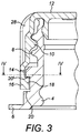
Figure 3 shows a longitudinal part-section through the fitment; -
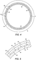
Figure 4 is a horizontal sectional view through the fitment at a level of a tamper-evident band on the line IV - IV ofFigure 3 ; and -
Figure 5 shows a detail ofFigure 4 . - Referring to the drawings, a
pour spout fitment 2 comprises atubular pour spout 4 incorporating anexternal flange 6 at its lower end. Theflange 6 may be sealed to the outside of a wall of a packaging container round a location at which a pouring hole is formed, or will be formed by the fitment; alternatively, it may be sealed to the inside of the wall and the fitment protrude externally from a hole through the wall. - The
spout 4 is formed with multi-start,external threading 8 which meshes with multi-start,internal threading 10 of ascrew cap 12 of the fitment. Thecap 12 is connected viabridges 14 to a tamper-evident band 16 of the fitment, thebridges 14 being distributed around the periphery of thecap 12. - The
band 16 includes anannular flange 18 which projects into anannular slot 20 in the outside of thespout 4. At a predetermined location around theslot 20 there projects radially outwardly from the spout into the slot at least two (in this case a group of four) tooth-form detents 22, for co-operating with at least one of a plurality (in this case three) of tooth-form detents 24 equispaced around and projecting from the inner periphery of theflange 18. Thedetents 22 are in a single group spaced peripherally through 15° from each other, while thedetents 24 are, of course, spaced peripherally from each other through 120°. The intention is that, upon unscrewing of thecap 12, thebridges 14 should break at the time when one of thedetents 24 interdigitates with two of thedents 22. Although, thus only twodetents 22 would appear to be required, the tolerances in moulding of the ribs and thus the angle of turning of thecap 12 relative to thespout 4 necessary to assure complete breaking of the bridges is relatively large, which is why fourdetents 22 are provided over an angle of 45°. Of course, with tighter tolerances in moulding of thebridges 14, three, or maybe even two,detents 22 could be sufficient. The number (three) ofdetents 24 equals the number (three) of starts of eachthreading - The angle of turning required before complete breaking depends on the number of
detents 24 and of the thread starts. For example, one detent 24 and one thread might require an angle of 360°. - As seen in
Figure 1 , the external peripheral surfaces of thecap 12 and theband 16 are formed with a vertical coloured printedmark 26 consisting of a part 26' on the cap and apart 26" on the band. The colour (e.g. red) of themark 26 contrasts with the colour(s) (e.g. white) of the cap and the band. The external peripheral surface of thecap 12 is formed with knurling 28. - The method of opening and reclosing of the
fitment 2 is as follows. - The
cap 12, accompanied by theband 16, is turned relative to thespout 4. As its turning increases beyond about 60°, thebridges 14 are broken, because theflange 18 remains detained against axial movement by the upper surface 20' of theslot 20. Once a detent 22 is engaged between a pair ofdetents 24, theband 16 remains held in a limited peripheral position relative to thespout 4. As illustrated byFigure 2 , upon full reclosing of thecap 12, the mark part 26' is visually identifiably displaced through about 60° relative to themark part 26".
Claims (8)
- A pour spout fitment (2) comprising an externally threaded, tubular pour spout (4), an internally threaded cap (12) whereof the threading (10) co-operates with the external threading (8) of the spout (4), a tamper-evident band (16) co-axially and frangibly attached to an inner end of said cap (12), a substantially annular slot (20) substantially co-axial with and in one of said spout (4) and said band (16), a substantially annular flange (18) substantially co-axial with and provided by the other of said spout (4) and said band (16) and projecting into said slot (20), at least one detent (22, 24) in said slot (20), at least one detent (24) on said flange (18), a first external reference (26') on said cap (12), the arrangement being such that upon unscrewing of said cap (12), said at least one detent (22) on the spout (4) co-operates with said at least one detent (24) on the band (16) to detain the band (16) against turning movement relative to the spout (4) and to detain the band (16) in a position relative to the substantially fully reclosed cap (12), characterised in that the pour spout fitment (2) further comprises a second external reference (26") on said band (16) and in a predetermined relationship with said first external reference (26'), the arrangement being such that upon unscrewing of said cap (12), the reference (26") on the band (16) remains out of said predetermined relationship.
- A fitment according to Claim 1, wherein said flange (18) is provided by said tamper-evident band (16).
- A fitment according to Claim 1 or 2, wherein the detents (22, 24) comprise teeth operating with each other.
- A fitment according to any one of Claims 1 to 3, wherein said at least one detent (24) on said band (16) faces substantially radially inwards and said at least one detent (22) on said spout (4) faces substantially radially outwards.
- A fitment according to any one of Claims 1 to 4, wherein said internal threading (10) and said external threading (8) each have a plurality of starts.
- A fitment according to Claim 5, wherein said plurality of starts is at least three.
- A fitment according to any one of Claims 1 to 6, wherein each of the references (26) is coloured contrastingly with the colour(s) of the cap (12) and the band (16).
- A fitment according to any one of Claims 1 to 7, wherein said references (26) have been printed onto said cap (12) and said band (16).
Applications Claiming Priority (1)
| Application Number | Priority Date | Filing Date | Title |
|---|---|---|---|
| PCT/GB2017/000036 WO2018172722A1 (en) | 2017-03-18 | 2017-03-18 | Pour spout fitment and method for opening said fitment |
Publications (2)
| Publication Number | Publication Date |
|---|---|
| EP3595983A1 EP3595983A1 (en) | 2020-01-22 |
| EP3595983B1 true EP3595983B1 (en) | 2021-05-05 |
Family
ID=58633025
Family Applications (1)
| Application Number | Title | Priority Date | Filing Date |
|---|---|---|---|
| EP17719671.4A Active EP3595983B1 (en) | 2017-03-18 | 2017-03-18 | Pour spout fitment |
Country Status (2)
| Country | Link |
|---|---|
| EP (1) | EP3595983B1 (en) |
| WO (1) | WO2018172722A1 (en) |
Families Citing this family (1)
| Publication number | Priority date | Publication date | Assignee | Title |
|---|---|---|---|---|
| DE102024116634A1 (en) * | 2024-06-13 | 2025-12-18 | PFABO GmbH | Reusable packaging with indicator device and method for closing a reusable package |
Family Cites Families (7)
| Publication number | Priority date | Publication date | Assignee | Title |
|---|---|---|---|---|
| US2201205A (en) * | 1938-04-08 | 1940-05-21 | Samburg Maurice | Tamperproof closure |
| GB8816719D0 (en) * | 1988-07-14 | 1988-08-17 | Rothwells Pickles Ltd | Improvements in & relating to tamper-evidence containers |
| US5944207A (en) * | 1995-10-30 | 1999-08-31 | Reidenbach; Bryan L. | Bottle closure assembly |
| US20050252878A1 (en) * | 2004-05-03 | 2005-11-17 | Alcoa Closure Systems International | Tamper-evident package |
| GB2450939B (en) * | 2007-07-13 | 2012-02-01 | Obrist Closures Switzerland | Tamper-Evident closure |
| US7959034B2 (en) * | 2007-08-17 | 2011-06-14 | The Dial Corporation | Liquid product pouring and measuring package with drain-back spout fitment and tight-sealing measuring cup assembly |
| US8544666B2 (en) * | 2010-09-20 | 2013-10-01 | Mead Johnson Nutrition Company | Tamper-evident container system |
-
2017
- 2017-03-18 WO PCT/GB2017/000036 patent/WO2018172722A1/en not_active Ceased
- 2017-03-18 EP EP17719671.4A patent/EP3595983B1/en active Active
Also Published As
| Publication number | Publication date |
|---|---|
| WO2018172722A1 (en) | 2018-09-27 |
| EP3595983A1 (en) | 2020-01-22 |
Similar Documents
| Publication | Publication Date | Title |
|---|---|---|
| EP2782841B1 (en) | Tamper evident closure | |
| EP2949596A1 (en) | Container sealing device | |
| EP3303165B1 (en) | Tamper-evident closure | |
| EP3303166B1 (en) | A closure | |
| GB2375532A (en) | A tamper-evident anti-refill closure | |
| EP2776335B1 (en) | A tamper evident closure | |
| EP1379441B1 (en) | A closure | |
| CA2060207A1 (en) | Tamper-indicating plastic closure | |
| JP6247861B2 (en) | Cap for container | |
| CN101743175A (en) | Tamper-evident closure | |
| GB2105693A (en) | Closures and containers | |
| JP6045195B2 (en) | Cap for container | |
| KR20130044203A (en) | A closure for a container | |
| WO2018172722A1 (en) | Pour spout fitment and method for opening said fitment | |
| EP2877411B1 (en) | Tamper evident closure | |
| WO1999028205A1 (en) | Tamper-evident container closure | |
| JP5973764B2 (en) | Container lid | |
| RU2258647C2 (en) | Safety closure for bottles and similar articles | |
| EP3209573A1 (en) | Cap closure | |
| EP3344553B1 (en) | Container and recyclable tamper evident closure assembly | |
| US12325559B2 (en) | Closure device | |
| US20140054288A1 (en) | Tamper-Evident Closure | |
| GB2358626A (en) | Screw on container closures | |
| RU2824303C1 (en) | Closure device | |
| EP2280880B1 (en) | A decorative, tamperproof, closure |
Legal Events
| Date | Code | Title | Description |
|---|---|---|---|
| STAA | Information on the status of an ep patent application or granted ep patent |
Free format text: STATUS: UNKNOWN |
|
| STAA | Information on the status of an ep patent application or granted ep patent |
Free format text: STATUS: THE INTERNATIONAL PUBLICATION HAS BEEN MADE |
|
| PUAI | Public reference made under article 153(3) epc to a published international application that has entered the european phase |
Free format text: ORIGINAL CODE: 0009012 |
|
| STAA | Information on the status of an ep patent application or granted ep patent |
Free format text: STATUS: REQUEST FOR EXAMINATION WAS MADE |
|
| 17P | Request for examination filed |
Effective date: 20190918 |
|
| AK | Designated contracting states |
Kind code of ref document: A1 Designated state(s): AL AT BE BG CH CY CZ DE DK EE ES FI FR GB GR HR HU IE IS IT LI LT LU LV MC MK MT NL NO PL PT RO RS SE SI SK SM TR |
|
| AX | Request for extension of the european patent |
Extension state: BA ME |
|
| DAV | Request for validation of the european patent (deleted) | ||
| DAX | Request for extension of the european patent (deleted) | ||
| GRAP | Despatch of communication of intention to grant a patent |
Free format text: ORIGINAL CODE: EPIDOSNIGR1 |
|
| STAA | Information on the status of an ep patent application or granted ep patent |
Free format text: STATUS: GRANT OF PATENT IS INTENDED |
|
| INTG | Intention to grant announced |
Effective date: 20201218 |
|
| GRAS | Grant fee paid |
Free format text: ORIGINAL CODE: EPIDOSNIGR3 |
|
| GRAA | (expected) grant |
Free format text: ORIGINAL CODE: 0009210 |
|
| STAA | Information on the status of an ep patent application or granted ep patent |
Free format text: STATUS: THE PATENT HAS BEEN GRANTED |
|
| AK | Designated contracting states |
Kind code of ref document: B1 Designated state(s): AL AT BE BG CH CY CZ DE DK EE ES FI FR GB GR HR HU IE IS IT LI LT LU LV MC MK MT NL NO PL PT RO RS SE SI SK SM TR |
|
| REG | Reference to a national code |
Ref country code: GB Ref legal event code: FG4D |
|
| REG | Reference to a national code |
Ref country code: CH Ref legal event code: EP |
|
| REG | Reference to a national code |
Ref country code: AT Ref legal event code: REF Ref document number: 1389568 Country of ref document: AT Kind code of ref document: T Effective date: 20210515 |
|
| REG | Reference to a national code |
Ref country code: IE Ref legal event code: FG4D |
|
| REG | Reference to a national code |
Ref country code: DE Ref legal event code: R096 Ref document number: 602017038066 Country of ref document: DE |
|
| REG | Reference to a national code |
Ref country code: LT Ref legal event code: MG9D |
|
| REG | Reference to a national code |
Ref country code: AT Ref legal event code: MK05 Ref document number: 1389568 Country of ref document: AT Kind code of ref document: T Effective date: 20210505 |
|
| PG25 | Lapsed in a contracting state [announced via postgrant information from national office to epo] |
Ref country code: LT Free format text: LAPSE BECAUSE OF FAILURE TO SUBMIT A TRANSLATION OF THE DESCRIPTION OR TO PAY THE FEE WITHIN THE PRESCRIBED TIME-LIMIT Effective date: 20210505 Ref country code: FI Free format text: LAPSE BECAUSE OF FAILURE TO SUBMIT A TRANSLATION OF THE DESCRIPTION OR TO PAY THE FEE WITHIN THE PRESCRIBED TIME-LIMIT Effective date: 20210505 Ref country code: BG Free format text: LAPSE BECAUSE OF FAILURE TO SUBMIT A TRANSLATION OF THE DESCRIPTION OR TO PAY THE FEE WITHIN THE PRESCRIBED TIME-LIMIT Effective date: 20210805 Ref country code: AT Free format text: LAPSE BECAUSE OF FAILURE TO SUBMIT A TRANSLATION OF THE DESCRIPTION OR TO PAY THE FEE WITHIN THE PRESCRIBED TIME-LIMIT Effective date: 20210505 Ref country code: HR Free format text: LAPSE BECAUSE OF FAILURE TO SUBMIT A TRANSLATION OF THE DESCRIPTION OR TO PAY THE FEE WITHIN THE PRESCRIBED TIME-LIMIT Effective date: 20210505 |
|
| PG25 | Lapsed in a contracting state [announced via postgrant information from national office to epo] |
Ref country code: LV Free format text: LAPSE BECAUSE OF FAILURE TO SUBMIT A TRANSLATION OF THE DESCRIPTION OR TO PAY THE FEE WITHIN THE PRESCRIBED TIME-LIMIT Effective date: 20210505 Ref country code: IS Free format text: LAPSE BECAUSE OF FAILURE TO SUBMIT A TRANSLATION OF THE DESCRIPTION OR TO PAY THE FEE WITHIN THE PRESCRIBED TIME-LIMIT Effective date: 20210905 Ref country code: GR Free format text: LAPSE BECAUSE OF FAILURE TO SUBMIT A TRANSLATION OF THE DESCRIPTION OR TO PAY THE FEE WITHIN THE PRESCRIBED TIME-LIMIT Effective date: 20210806 Ref country code: RS Free format text: LAPSE BECAUSE OF FAILURE TO SUBMIT A TRANSLATION OF THE DESCRIPTION OR TO PAY THE FEE WITHIN THE PRESCRIBED TIME-LIMIT Effective date: 20210505 Ref country code: SE Free format text: LAPSE BECAUSE OF FAILURE TO SUBMIT A TRANSLATION OF THE DESCRIPTION OR TO PAY THE FEE WITHIN THE PRESCRIBED TIME-LIMIT Effective date: 20210505 Ref country code: PT Free format text: LAPSE BECAUSE OF FAILURE TO SUBMIT A TRANSLATION OF THE DESCRIPTION OR TO PAY THE FEE WITHIN THE PRESCRIBED TIME-LIMIT Effective date: 20210906 Ref country code: PL Free format text: LAPSE BECAUSE OF FAILURE TO SUBMIT A TRANSLATION OF THE DESCRIPTION OR TO PAY THE FEE WITHIN THE PRESCRIBED TIME-LIMIT Effective date: 20210505 Ref country code: NO Free format text: LAPSE BECAUSE OF FAILURE TO SUBMIT A TRANSLATION OF THE DESCRIPTION OR TO PAY THE FEE WITHIN THE PRESCRIBED TIME-LIMIT Effective date: 20210805 |
|
| REG | Reference to a national code |
Ref country code: NL Ref legal event code: MP Effective date: 20210505 |
|
| PG25 | Lapsed in a contracting state [announced via postgrant information from national office to epo] |
Ref country code: NL Free format text: LAPSE BECAUSE OF FAILURE TO SUBMIT A TRANSLATION OF THE DESCRIPTION OR TO PAY THE FEE WITHIN THE PRESCRIBED TIME-LIMIT Effective date: 20210505 |
|
| PG25 | Lapsed in a contracting state [announced via postgrant information from national office to epo] |
Ref country code: DK Free format text: LAPSE BECAUSE OF FAILURE TO SUBMIT A TRANSLATION OF THE DESCRIPTION OR TO PAY THE FEE WITHIN THE PRESCRIBED TIME-LIMIT Effective date: 20210505 Ref country code: EE Free format text: LAPSE BECAUSE OF FAILURE TO SUBMIT A TRANSLATION OF THE DESCRIPTION OR TO PAY THE FEE WITHIN THE PRESCRIBED TIME-LIMIT Effective date: 20210505 Ref country code: CZ Free format text: LAPSE BECAUSE OF FAILURE TO SUBMIT A TRANSLATION OF THE DESCRIPTION OR TO PAY THE FEE WITHIN THE PRESCRIBED TIME-LIMIT Effective date: 20210505 Ref country code: RO Free format text: LAPSE BECAUSE OF FAILURE TO SUBMIT A TRANSLATION OF THE DESCRIPTION OR TO PAY THE FEE WITHIN THE PRESCRIBED TIME-LIMIT Effective date: 20210505 Ref country code: ES Free format text: LAPSE BECAUSE OF FAILURE TO SUBMIT A TRANSLATION OF THE DESCRIPTION OR TO PAY THE FEE WITHIN THE PRESCRIBED TIME-LIMIT Effective date: 20210505 Ref country code: SK Free format text: LAPSE BECAUSE OF FAILURE TO SUBMIT A TRANSLATION OF THE DESCRIPTION OR TO PAY THE FEE WITHIN THE PRESCRIBED TIME-LIMIT Effective date: 20210505 Ref country code: SM Free format text: LAPSE BECAUSE OF FAILURE TO SUBMIT A TRANSLATION OF THE DESCRIPTION OR TO PAY THE FEE WITHIN THE PRESCRIBED TIME-LIMIT Effective date: 20210505 |
|
| REG | Reference to a national code |
Ref country code: DE Ref legal event code: R097 Ref document number: 602017038066 Country of ref document: DE |
|
| PLBE | No opposition filed within time limit |
Free format text: ORIGINAL CODE: 0009261 |
|
| STAA | Information on the status of an ep patent application or granted ep patent |
Free format text: STATUS: NO OPPOSITION FILED WITHIN TIME LIMIT |
|
| 26N | No opposition filed |
Effective date: 20220208 |
|
| PG25 | Lapsed in a contracting state [announced via postgrant information from national office to epo] |
Ref country code: IS Free format text: LAPSE BECAUSE OF FAILURE TO SUBMIT A TRANSLATION OF THE DESCRIPTION OR TO PAY THE FEE WITHIN THE PRESCRIBED TIME-LIMIT Effective date: 20210905 Ref country code: AL Free format text: LAPSE BECAUSE OF FAILURE TO SUBMIT A TRANSLATION OF THE DESCRIPTION OR TO PAY THE FEE WITHIN THE PRESCRIBED TIME-LIMIT Effective date: 20210505 |
|
| PG25 | Lapsed in a contracting state [announced via postgrant information from national office to epo] |
Ref country code: IT Free format text: LAPSE BECAUSE OF FAILURE TO SUBMIT A TRANSLATION OF THE DESCRIPTION OR TO PAY THE FEE WITHIN THE PRESCRIBED TIME-LIMIT Effective date: 20210505 |
|
| PG25 | Lapsed in a contracting state [announced via postgrant information from national office to epo] |
Ref country code: MC Free format text: LAPSE BECAUSE OF FAILURE TO SUBMIT A TRANSLATION OF THE DESCRIPTION OR TO PAY THE FEE WITHIN THE PRESCRIBED TIME-LIMIT Effective date: 20210505 |
|
| REG | Reference to a national code |
Ref country code: CH Ref legal event code: PL |
|
| REG | Reference to a national code |
Ref country code: BE Ref legal event code: MM Effective date: 20220331 |
|
| PG25 | Lapsed in a contracting state [announced via postgrant information from national office to epo] |
Ref country code: LU Free format text: LAPSE BECAUSE OF NON-PAYMENT OF DUE FEES Effective date: 20220318 Ref country code: LI Free format text: LAPSE BECAUSE OF NON-PAYMENT OF DUE FEES Effective date: 20220331 Ref country code: IE Free format text: LAPSE BECAUSE OF NON-PAYMENT OF DUE FEES Effective date: 20220318 Ref country code: CH Free format text: LAPSE BECAUSE OF NON-PAYMENT OF DUE FEES Effective date: 20220331 |
|
| PG25 | Lapsed in a contracting state [announced via postgrant information from national office to epo] |
Ref country code: BE Free format text: LAPSE BECAUSE OF NON-PAYMENT OF DUE FEES Effective date: 20220331 |
|
| PG25 | Lapsed in a contracting state [announced via postgrant information from national office to epo] |
Ref country code: MK Free format text: LAPSE BECAUSE OF FAILURE TO SUBMIT A TRANSLATION OF THE DESCRIPTION OR TO PAY THE FEE WITHIN THE PRESCRIBED TIME-LIMIT Effective date: 20210505 Ref country code: CY Free format text: LAPSE BECAUSE OF FAILURE TO SUBMIT A TRANSLATION OF THE DESCRIPTION OR TO PAY THE FEE WITHIN THE PRESCRIBED TIME-LIMIT Effective date: 20210505 |
|
| PG25 | Lapsed in a contracting state [announced via postgrant information from national office to epo] |
Ref country code: HU Free format text: LAPSE BECAUSE OF FAILURE TO SUBMIT A TRANSLATION OF THE DESCRIPTION OR TO PAY THE FEE WITHIN THE PRESCRIBED TIME-LIMIT; INVALID AB INITIO Effective date: 20170318 |
|
| PG25 | Lapsed in a contracting state [announced via postgrant information from national office to epo] |
Ref country code: MT Free format text: LAPSE BECAUSE OF FAILURE TO SUBMIT A TRANSLATION OF THE DESCRIPTION OR TO PAY THE FEE WITHIN THE PRESCRIBED TIME-LIMIT Effective date: 20210505 |
|
| PG25 | Lapsed in a contracting state [announced via postgrant information from national office to epo] |
Ref country code: TR Free format text: LAPSE BECAUSE OF FAILURE TO SUBMIT A TRANSLATION OF THE DESCRIPTION OR TO PAY THE FEE WITHIN THE PRESCRIBED TIME-LIMIT Effective date: 20210505 |
|
| PGFP | Annual fee paid to national office [announced via postgrant information from national office to epo] |
Ref country code: GB Payment date: 20260213 Year of fee payment: 10 |
|
| PGFP | Annual fee paid to national office [announced via postgrant information from national office to epo] |
Ref country code: DE Payment date: 20260216 Year of fee payment: 10 |
|
| PGFP | Annual fee paid to national office [announced via postgrant information from national office to epo] |
Ref country code: FR Payment date: 20260212 Year of fee payment: 10 |