EP3595766B1 - Hemostasis valves and methods for making and using hemostasis valves - Google Patents
Hemostasis valves and methods for making and using hemostasis valves Download PDFInfo
- Publication number
- EP3595766B1 EP3595766B1 EP18710698.4A EP18710698A EP3595766B1 EP 3595766 B1 EP3595766 B1 EP 3595766B1 EP 18710698 A EP18710698 A EP 18710698A EP 3595766 B1 EP3595766 B1 EP 3595766B1
- Authority
- EP
- European Patent Office
- Prior art keywords
- end region
- proximal end
- main body
- cartridge
- seal member
- Prior art date
- Legal status (The legal status is an assumption and is not a legal conclusion. Google has not performed a legal analysis and makes no representation as to the accuracy of the status listed.)
- Active
Links
Images




Classifications
-
- A—HUMAN NECESSITIES
- A61—MEDICAL OR VETERINARY SCIENCE; HYGIENE
- A61M—DEVICES FOR INTRODUCING MEDIA INTO, OR ONTO, THE BODY; DEVICES FOR TRANSDUCING BODY MEDIA OR FOR TAKING MEDIA FROM THE BODY; DEVICES FOR PRODUCING OR ENDING SLEEP OR STUPOR
- A61M39/00—Tubes, tube connectors, tube couplings, valves, access sites or the like, specially adapted for medical use
- A61M39/02—Access sites
- A61M39/06—Haemostasis valves, i.e. gaskets sealing around a needle, catheter or the like, closing on removal thereof
- A61M39/0613—Haemostasis valves, i.e. gaskets sealing around a needle, catheter or the like, closing on removal thereof with means for adjusting the seal opening or pressure
-
- A—HUMAN NECESSITIES
- A61—MEDICAL OR VETERINARY SCIENCE; HYGIENE
- A61M—DEVICES FOR INTRODUCING MEDIA INTO, OR ONTO, THE BODY; DEVICES FOR TRANSDUCING BODY MEDIA OR FOR TAKING MEDIA FROM THE BODY; DEVICES FOR PRODUCING OR ENDING SLEEP OR STUPOR
- A61M39/00—Tubes, tube connectors, tube couplings, valves, access sites or the like, specially adapted for medical use
- A61M39/02—Access sites
- A61M39/06—Haemostasis valves, i.e. gaskets sealing around a needle, catheter or the like, closing on removal thereof
-
- A—HUMAN NECESSITIES
- A61—MEDICAL OR VETERINARY SCIENCE; HYGIENE
- A61M—DEVICES FOR INTRODUCING MEDIA INTO, OR ONTO, THE BODY; DEVICES FOR TRANSDUCING BODY MEDIA OR FOR TAKING MEDIA FROM THE BODY; DEVICES FOR PRODUCING OR ENDING SLEEP OR STUPOR
- A61M39/00—Tubes, tube connectors, tube couplings, valves, access sites or the like, specially adapted for medical use
- A61M39/02—Access sites
- A61M39/06—Haemostasis valves, i.e. gaskets sealing around a needle, catheter or the like, closing on removal thereof
- A61M2039/062—Haemostasis valves, i.e. gaskets sealing around a needle, catheter or the like, closing on removal thereof used with a catheter
-
- A—HUMAN NECESSITIES
- A61—MEDICAL OR VETERINARY SCIENCE; HYGIENE
- A61M—DEVICES FOR INTRODUCING MEDIA INTO, OR ONTO, THE BODY; DEVICES FOR TRANSDUCING BODY MEDIA OR FOR TAKING MEDIA FROM THE BODY; DEVICES FOR PRODUCING OR ENDING SLEEP OR STUPOR
- A61M39/00—Tubes, tube connectors, tube couplings, valves, access sites or the like, specially adapted for medical use
- A61M39/02—Access sites
- A61M39/06—Haemostasis valves, i.e. gaskets sealing around a needle, catheter or the like, closing on removal thereof
- A61M2039/0633—Haemostasis valves, i.e. gaskets sealing around a needle, catheter or the like, closing on removal thereof the seal being a passive seal made of a resilient material with or without an opening
-
- A—HUMAN NECESSITIES
- A61—MEDICAL OR VETERINARY SCIENCE; HYGIENE
- A61M—DEVICES FOR INTRODUCING MEDIA INTO, OR ONTO, THE BODY; DEVICES FOR TRANSDUCING BODY MEDIA OR FOR TAKING MEDIA FROM THE BODY; DEVICES FOR PRODUCING OR ENDING SLEEP OR STUPOR
- A61M39/00—Tubes, tube connectors, tube couplings, valves, access sites or the like, specially adapted for medical use
- A61M39/02—Access sites
- A61M39/06—Haemostasis valves, i.e. gaskets sealing around a needle, catheter or the like, closing on removal thereof
- A61M2039/0633—Haemostasis valves, i.e. gaskets sealing around a needle, catheter or the like, closing on removal thereof the seal being a passive seal made of a resilient material with or without an opening
- A61M2039/064—Slit-valve
-
- A—HUMAN NECESSITIES
- A61—MEDICAL OR VETERINARY SCIENCE; HYGIENE
- A61M—DEVICES FOR INTRODUCING MEDIA INTO, OR ONTO, THE BODY; DEVICES FOR TRANSDUCING BODY MEDIA OR FOR TAKING MEDIA FROM THE BODY; DEVICES FOR PRODUCING OR ENDING SLEEP OR STUPOR
- A61M39/00—Tubes, tube connectors, tube couplings, valves, access sites or the like, specially adapted for medical use
- A61M39/02—Access sites
- A61M39/06—Haemostasis valves, i.e. gaskets sealing around a needle, catheter or the like, closing on removal thereof
- A61M2039/0686—Haemostasis valves, i.e. gaskets sealing around a needle, catheter or the like, closing on removal thereof comprising more than one seal
-
- A—HUMAN NECESSITIES
- A61—MEDICAL OR VETERINARY SCIENCE; HYGIENE
- A61M—DEVICES FOR INTRODUCING MEDIA INTO, OR ONTO, THE BODY; DEVICES FOR TRANSDUCING BODY MEDIA OR FOR TAKING MEDIA FROM THE BODY; DEVICES FOR PRODUCING OR ENDING SLEEP OR STUPOR
- A61M2207/00—Methods of manufacture, assembly or production
-
- A—HUMAN NECESSITIES
- A61—MEDICAL OR VETERINARY SCIENCE; HYGIENE
- A61M—DEVICES FOR INTRODUCING MEDIA INTO, OR ONTO, THE BODY; DEVICES FOR TRANSDUCING BODY MEDIA OR FOR TAKING MEDIA FROM THE BODY; DEVICES FOR PRODUCING OR ENDING SLEEP OR STUPOR
- A61M39/00—Tubes, tube connectors, tube couplings, valves, access sites or the like, specially adapted for medical use
- A61M39/02—Access sites
- A61M39/06—Haemostasis valves, i.e. gaskets sealing around a needle, catheter or the like, closing on removal thereof
- A61M39/0693—Haemostasis valves, i.e. gaskets sealing around a needle, catheter or the like, closing on removal thereof including means for seal penetration
Definitions
- the present disclosure pertains to medical devices, and methods for manufacturing medical devices. More particularly, the present disclosure pertains to hemostasis valves and methods for making and using hemostasis valves
- US 2001/021825 A1 discloses a bleedback control assembly for controlling blood loss during vascular diagnostics.
- WO 2009/139981 A2 discloses a valve apparatus for use with bloodless exchange of elongate instruments into a patient's vasculature.
- US 5 935 112 A discloses a hemostasis valve that includes one or more seals that is able to accommodate both large and small diameter catheters and guidewires.
- the hemostasis valve comprises: a main body having a distal end region and a proximal end region; a first seal member disposed within the proximal end region of the main body; a cartridge at least partially disposed within the proximal end region of the main body, the cartridge including a second seal member; wherein the cartridge has one or more projections formed thereon; wherein the proximal end region of the main body has one or more recesses formed therein, the one or more recesses being designed to engage the one or more projections; and a plunger coupled to the proximal end region of the main body.
- the one or more recesses comprise one or more grooves formed along an inner surface of the proximal end region of the main body.
- the one or more recesses comprise one or more slots formed along the proximal end region of the main body.
- Engagement of the one or more projections with the one or more recesses is designed to limit rotation of the cartridge relative to the proximal end region of the main body.
- proximal end region of the main body includes one or more threads.
- the cartridge includes two projections positioned along opposing sides of the cartridge.
- the proximal end region of the main body includes two recesses.
- a hemostasis valve comprises: a main body having a distal end region, a side port, and a proximal end region; a high pressure seal member disposed within the proximal end region of the main body; a cartridge at least partially disposed within the proximal end region of the main body, the cartridge including a low pressure seal member; wherein the cartridge has one or more projections formed thereon; wherein the proximal end region of the main body has one or more recesses formed therein, the one or more recesses being designed to engage the one or more projections so as to limit rotation of the cartridge relative to the proximal end region of the main body; and a plunger coupled to the proximal end region of the main body.
- the one or more recesses comprise one or more grooves formed along an inner surface of the proximal end region of the main body.
- the one or more recesses comprise one or more slots formed along the proximal end region of the main body.
- the cartridge includes two projections positioned along opposing sides of the cartridge.
- the proximal end region of the main body includes two recesses.
- a hemostasis valve comprises: a main body having a threaded proximal end region; a nut threadably engaged with the threaded proximal end region; a first seal member disposed within the threaded proximal end region of the main body; a cartridge at least partially disposed within the threaded proximal end region of the main body, the cartridge including a second seal member; wherein the cartridge a pair of opposing projections formed thereon; and wherein the threaded proximal end region of the main body has a pair of opposing recesses formed therein, the recesses being designed to engage the projections so as to limit rotation of the cartridge relative to the threaded proximal end region of the main body.
- the recesses comprise grooves formed along an inner surface of the threaded proximal end region of the main body.
- the recesses comprise slots formed along the threaded proximal end region of the main body.
- the first seal member comprises a high pressure seal.
- the second seal member comprises a low pressure seal with at least one cut, slit, or slot formed therein.
- references in the specification to "an embodiment”, “some embodiments”, “other embodiments”, etc. indicate that the embodiment described may include one or more particular features, structures, and/or characteristics. However, such recitations do not necessarily mean that all embodiments include the particular features, structures, and/or characteristics. Additionally, when particular features, structures, and/or characteristics are described in connection with one embodiment, it should be understood that such features, structures, and/or characteristics may also be used connection with other embodiments whether or not explicitly described unless clearly stated to the contrary.
- the hemostasis valve 10 includes a main body 12.
- the main body 12 may include a side port 14.
- the side port 14 may be connected to another device such as an infusion device, an inflation device, or the like.
- An adapter 16 may be coupled to the distal end of the main body 12.
- the adapter 16 may be used to couple the hemostasis valve 10 to a device such as a catheter.
- a plunger 18 is coupled to the proximal end of the main body 12.
- the plunger 18 may be used to activate or otherwise close a seal (e.g., as discussed herein) within the hemostasis valve 10.
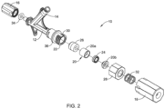
- FIG. 2 is an exploded view of the hemostasis valve 10.
- the hemostasis valve 10 includes a cartridge 20.
- the cartridge 20 which may include two pieces 20a, 20b that are coupled to one another (e.g., press fit, thermally bonded, adhesively bonded, etc.), may be arranged so that at least a portion thereof can be disposed within a proximal end region 22 of the main body 12.
- a first seal member 24 is disposed within the cartridge 20.
- a second seal member 26 is disposed within the proximal end region 22 of the main body 12. In at least some instances, the second seal member 26 may be disposed distally of the cartridge 20.
- the hemostasis valve 10 may include a spring member 32 and an O-ring 34.
- the spring member 32 may be coupled to the plunger 18. In at least some instances, the spring member 32 may be designed to exert a proximally directed force on the plunger 18.
- the O-ring 34 may be positioned adjacent to the adapter 16.
- a ring member or "snap ring" 36 may be disposed along the proximal end region 22 of the main body 12.
- FIG. 3 is a cross-sectional view the hemostasis valve 10.
- the hemostasis valve 10 may include a central lumen 38.
- the central lumen 38 is designed to be placed into fluid communication with one or more lumens of a device coupled to the adapter 16.
- a second or infusion lumen 40 may be defined adjacent to the side port 14. The second lumen 40 may be in fluid communication with the central lumen 38.
- the hemostasis valve 10 is designed so that it may be coupled to another device.
- the adapter 16 which may take the form of a Tuohy-Borst or other type of connector, may be engaged with the proximal end of the other device.
- the second seal member 26 When connected (and with the plunger 18 in the configuration shown in FIG. 3 ), the second seal member 26 may be in an open state or configuration.
- the first seal member 24 may be in a closed or sealed configuration when the hemostasis valve 10 is connected to the other device (and with the plunger 18 in the configuration shown in FIG. 3 ).
- the hemostasis valve 10 when the hemostasis valve 10 is connected to another device and in the configuration shown in FIG. 3 , the hemostasis valve 10 is able to substantially hold a fluid-tight seal that substantially prevents the backflow and/or leakage of body fluids (e.g., blood).
- body fluids e.g., blood
- the first seal member 24 may be designed to substantially prevent the backflow and/or leakage of relatively-low pressure fluids, if the infusion device infuses fluids at a relatively high pressure, it is possible that the infusion fluid may be able to flow through the first seal member 24.
- the hemostasis valve 10 can be actuated to close or "seal" the second seal member 26.
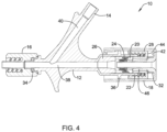
- the plunger 18 may initially be urged distally until a distally-facing, proximal end surface or cap 42 of the plunger 18 is disposed adjacent to a proximal end region 44 of the nut 28 as shown in FIG. 4 .
- a tubular region 46 of the plunger 18 may extend through (and open) the first seal member 24.
- a portion of the plunger 18 may move distally beyond the ring member 36.
- the plunger 18 can be rotated (e.g., in a clockwise direction) to close the second seal member 26 as shown in FIG. 5A .
- This rotation may cause the nut 28 to rotate and move distally.
- distal movement of the nut 28 urges the cartridge 20 distally within the proximal end region 22 of the main body 12 such that the cartridge 20 engages and deforms the second seal member 26, thereby shifting the second seal member 26 to the closed or sealed configuration.
- the plunger 18 may be released or otherwise allowed to move proximally, as shown in FIG. 5B , which may reclose the first seal member 24 (while the second seal member 26 remains closed).
- Rotational movement of the nut 28 causes the nut 28 to translate and engage the cartridge 20, which in turn engages and closes the second seal member 26.
- the axial movement of the cartridge applies an axial force onto the second seal member 26, which closes or "seals" the second seal member 26. If the rotational movement of the nut 28 causes the cartridge 20 to rotate, this could lead to rotational forces begin applied to the second seal member 26. If this happens, the second seal member 26 could become distorted/twisted in such a manner that the second seal member 26 may not completely close off or seal the main lumen 38. It may be desirable to limit rotational forces being applied to the cartridge 20 and/or the second seal member 26. Disclosed herein are hemostasis valves that are designed to limit such forces.
- the cartridge 120 When axial forces are applied to the cartridge 120 (e.g., by the nut 28), the cartridge 120 will begin to translate relative to the main body 112. When doing so, the projections 150 will translate along the recesses 148 as shown in FIG. 7 . Because of structural relationship between the projections 150 and the recesses 148, rotation of the cartridge 120 is reduced or otherwise eliminated as the cartridge moves distally within the proximal end region 122.
- the proximal end region 122 may include a single recess 148, two recesses 148, three recesses 148, four recesses 148, or more.
- the recesses 148 may be arranged in a number of suitable manners. In some instances, the recesses 148 may be evenly spaced about the proximal end region 122. Alternatively, the recesses 148 may be unevenly spaced.
- the cartridge 120 may include a suitable number of projections 150 such as one, two, three, four, five, six, or more. The projections 150 may be evenly spaced or unevenly spaced about the cartridge 120. In some instances, the number of projections 150 and the number of recesses 148 may be the same. Alternatively, the number of projections 150 may differ from the number of recesses 148.
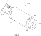
- FIG. 8 illustrates a portion of an example hemostasis valve 210 that is similar in form and function to other hemostasis valves disclosed herein.
- the proximal end region 222 of the main body 212 may include one or more internal grooves 248.
- the cartridge 220 may include one or more wings or projections 250. The projections 250 may extend along a portion of the length of the cartridge 220 or a portion of the length. When the cartridge 220 is disposed within the proximal end region 222 of the main body 212, the wings 250 may fit within the grooves 248. Because of this, rotation of the cartridge 220 is reduced or otherwise eliminated as the cartridge moves distally within the proximal end region 222 as shown in FIG. 9 .
- the materials that can be used for the various components of the hemostasis valve 10 (and/or other hemostasis valves disclosed herein) and the various components thereof disclosed herein may include those commonly associated with medical devices.
- the following discussion makes reference to the main body 12 and other components of the hemostasis valve 10. However, this is not intended to limit the devices and methods described herein, as the discussion may be applied to other hemostasis valves and/or components thereof disclosed herein.
- the main body 12 and/or other components of the hemostasis valve 10 may be made from a metal, metal alloy, polymer (some examples of which are disclosed below), a metal-polymer composite, ceramics, combinations thereof, and the like, or other suitable material.
- suitable polymers may include polytetrafluoroethylene (PTFE), ethylene tetrafluoroethylene (ETFE), fluorinated ethylene propylene (FEP), polyoxymethylene (POM, for example, DELRIN ® available from DuPont), polyether block ester, polyurethane (for example, Polyurethane 85A), polypropylene (PP), polyvinylchloride (PVC), polyether-ester (for example, ARNITEL ® available from DSM Engineering Plastics), ether or ester based copolymers (for example, butylene/poly(alkylene ether) phthalate and/or other polyester elastomers such as HYTREL ® available from DuPont), polyamide (for example,
- suitable metals and metal alloys include stainless steel, such as 304V, 304L, and 316LV stainless steel; mild steel; nickel-titanium alloy such as linear-elastic and/or super-elastic nitinol; other nickel alloys such as nickel-chromium-molybdenum alloys (e.g., UNS: N06625 such as INCONEL ® 625, UNS: N06022 such as HASTELLOY ® C-22 ® , UNS: N10276 such as HASTELLOY ® C276 ® , other HASTELLOY ® alloys, and the like), nickel-copper alloys (e.g., UNS: N04400 such as MONEL ® 400, NICKELVAC ® 400, NICORROS ® 400, and the like), nickel-cobalt-chromium-molybdenum alloys (e.g., UNS: R30035 such as MP35-N ® and the like), nickel-co
Landscapes
- Health & Medical Sciences (AREA)
- Heart & Thoracic Surgery (AREA)
- Pulmonology (AREA)
- Engineering & Computer Science (AREA)
- Anesthesiology (AREA)
- Biomedical Technology (AREA)
- Hematology (AREA)
- Life Sciences & Earth Sciences (AREA)
- Animal Behavior & Ethology (AREA)
- General Health & Medical Sciences (AREA)
- Public Health (AREA)
- Veterinary Medicine (AREA)
- Infusion, Injection, And Reservoir Apparatuses (AREA)
Description
- This application claims the benefit of
U.S. Provisional Patent Application Serial No. 62/470,634 filed on March 13, 2017 - The present disclosure pertains to medical devices, and methods for manufacturing medical devices. More particularly, the present disclosure pertains to hemostasis valves and methods for making and using hemostasis valves
- A wide variety of medical devices have been developed for medical use, for example, intravascular use. Some of these devices include guidewires, catheters, and the like. These devices are manufactured by any one of a variety of different manufacturing methods and may be used according to any one of a variety of methods. Of the known medical devices and methods, each has certain advantages and disadvantages. There is an ongoing need to provide alternative medical devices as well as alternative methods for manufacturing and using medical devices.
US 2001/021825 A1 discloses a bleedback control assembly for controlling blood loss during vascular diagnostics. Furthermore,WO 2009/139981 A2 discloses a valve apparatus for use with bloodless exchange of elongate instruments into a patient's vasculature.US 5 935 112 A discloses a hemostasis valve that includes one or more seals that is able to accommodate both large and small diameter catheters and guidewires. - This disclosure provides design, material, manufacturing method, and use alternatives for medical devices. An example hemostasis valve is disclosed, as defined in claim 1. The hemostasis valve comprises: a main body having a distal end region and a proximal end region; a first seal member disposed within the proximal end region of the main body; a cartridge at least partially disposed within the proximal end region of the main body, the cartridge including a second seal member; wherein the cartridge has one or more projections formed thereon; wherein the proximal end region of the main body has one or more recesses formed therein, the one or more recesses being designed to engage the one or more projections; and a plunger coupled to the proximal end region of the main body.
- Alternatively or additionally to any of the embodiments above, the one or more recesses comprise one or more grooves formed along an inner surface of the proximal end region of the main body.
- Alternatively or additionally to any of the embodiments above, the one or more recesses comprise one or more slots formed along the proximal end region of the main body.
- Engagement of the one or more projections with the one or more recesses is designed to limit rotation of the cartridge relative to the proximal end region of the main body.
- Alternatively or additionally to any of the embodiments above, further comprising a ring member disposed along an outer surface of the proximal end region of the main body.
- Alternatively or additionally to any of the embodiments above, wherein the proximal end region of the main body includes one or more threads.
- Alternatively or additionally to any of the embodiments above, further comprising a nut threadably engaged with the one or more threads.
- Alternatively or additionally to any of the embodiments above, the cartridge includes two projections positioned along opposing sides of the cartridge.
- Alternatively or additionally to any of the embodiments above, the proximal end region of the main body includes two recesses.
- A hemostasis valve is disclosed. The hemostasis valve comprises: a main body having a distal end region, a side port, and a proximal end region; a high pressure seal member disposed within the proximal end region of the main body; a cartridge at least partially disposed within the proximal end region of the main body, the cartridge including a low pressure seal member; wherein the cartridge has one or more projections formed thereon; wherein the proximal end region of the main body has one or more recesses formed therein, the one or more recesses being designed to engage the one or more projections so as to limit rotation of the cartridge relative to the proximal end region of the main body; and a plunger coupled to the proximal end region of the main body.
- Alternatively or additionally to any of the embodiments above, the one or more recesses comprise one or more grooves formed along an inner surface of the proximal end region of the main body.
- Alternatively or additionally to any of the embodiments above, the one or more recesses comprise one or more slots formed along the proximal end region of the main body.
- Alternatively or additionally to any of the embodiments above, the cartridge includes two projections positioned along opposing sides of the cartridge.
- Alternatively or additionally to any of the embodiments above, the proximal end region of the main body includes two recesses.
- A hemostasis valve is disclosed. The hemostasis valve comprises: a main body having a threaded proximal end region; a nut threadably engaged with the threaded proximal end region; a first seal member disposed within the threaded proximal end region of the main body; a cartridge at least partially disposed within the threaded proximal end region of the main body, the cartridge including a second seal member; wherein the cartridge a pair of opposing projections formed thereon; and wherein the threaded proximal end region of the main body has a pair of opposing recesses formed therein, the recesses being designed to engage the projections so as to limit rotation of the cartridge relative to the threaded proximal end region of the main body.
- Alternatively or additionally to any of the embodiments above, the recesses comprise grooves formed along an inner surface of the threaded proximal end region of the main body.
- Alternatively or additionally to any of the embodiments above, the recesses comprise slots formed along the threaded proximal end region of the main body.
- Alternatively or additionally to any of the embodiments above, further comprising a plunger coupled to the threaded proximal end region of the main body.
- Alternatively or additionally to any of the embodiments above, the first seal member comprises a high pressure seal.
- Alternatively or additionally to any of the embodiments above, the second seal member comprises a low pressure seal with at least one cut, slit, or slot formed therein.
- The above summary of some embodiments is not intended to describe each disclosed embodiment or every implementation of the present disclosure. The Figures, and Detailed Description, which follow, more particularly exemplify these embodiments.
- The disclosure may be more completely understood in consideration of the following detailed description in connection with the accompanying drawings, in which:
-
FIG. 1 is a perspective view of an example hemostasis valve. -
FIG. 2 is an exploded view of an example hemostasis valve. -
FIG. 3 is a cross-sectional view taken through line 3-3 inFIG. 1 . -
FIG. 4 is a cross-sectional view of an example hemostasis valve. -
FIGS. 5A-5B is a cross-sectional view of an example hemostasis valve. -
FIG. 6 is a perspective view of a portion of an example hemostasis valve. -
FIG. 7 is a perspective view of a portion of an example hemostasis valve. -
FIG. 8 is a perspective view of a portion of an example hemostasis valve. -
FIG. 9 is a perspective view of a portion of an example hemostasis valve. - While the disclosure is amenable to various modifications and alternative forms, specifics thereof have been shown by way of example in the drawings and will be described in detail. It should be understood, however, that the intention is not to limit the invention to the particular embodiments described. On the contrary, the intention is to cover all alternatives falling within the scope of the disclosure.
- For the following defined terms, these definitions shall be applied, unless a different definition is given in the claims or elsewhere in this specification.
- All numeric values are herein assumed to be modified by the term "about", whether or not explicitly indicated. The term "about" generally refers to a range of numbers that one of skill in the art would consider equivalent to the recited value (e.g., having the same function or result). In many instances, the terms "about" may include numbers that are rounded to the nearest significant figure.
- The recitation of numerical ranges by endpoints includes all numbers within that range (e.g. 1 to 5 includes 1, 1.5, 2, 2.75, 3, 3.80, 4, and 5).
- As used in this specification and the appended claims, the singular forms "a", "an", and "the" include plural referents unless the content clearly dictates otherwise. As used in this specification and the appended claims, the term "or" is generally employed in its sense including "and/or" unless the content clearly dictates otherwise.
- It is noted that references in the specification to "an embodiment", "some embodiments", "other embodiments", etc., indicate that the embodiment described may include one or more particular features, structures, and/or characteristics. However, such recitations do not necessarily mean that all embodiments include the particular features, structures, and/or characteristics. Additionally, when particular features, structures, and/or characteristics are described in connection with one embodiment, it should be understood that such features, structures, and/or characteristics may also be used connection with other embodiments whether or not explicitly described unless clearly stated to the contrary.
- The following detailed description should be read with reference to the drawings in which similar elements in different drawings are numbered the same. The drawings, which are not necessarily to scale, depict illustrative embodiments and are not intended to limit the scope of the invention.
- A number of medical procedures, for example intravascular procedures, utilize medical devices within body lumens. For example, some intravascular procedures include the placement of a guidewire, guide catheter, interventional device, or the like in a blood vessel. Because fluid under pressure (e.g., blood) is present within the blood vessel, fluid could travel along or through the medical device and escape or leak from the patient. In some instances, it may be desirable to dispose a hemostasis valve or hemostasis valve assembly at the proximal end of a medical device to reduce or otherwise limit the leaking of fluids/blood from the proximal end of the device.
- An
example hemostasis valve 10 is shown inFIG. 1 . Thehemostasis valve 10 includes amain body 12. Themain body 12 may include aside port 14. Theside port 14 may be connected to another device such as an infusion device, an inflation device, or the like. Anadapter 16 may be coupled to the distal end of themain body 12. Theadapter 16 may be used to couple thehemostasis valve 10 to a device such as a catheter. Aplunger 18 is coupled to the proximal end of themain body 12. Theplunger 18 may be used to activate or otherwise close a seal (e.g., as discussed herein) within thehemostasis valve 10. These and other features of thehemostasis valve 10 are discussed herein. -
FIG. 2 is an exploded view of thehemostasis valve 10. Here, the various components of thehemostasis valve 10 can be seen. Thehemostasis valve 10 includes acartridge 20. Thecartridge 20, which may include twopieces proximal end region 22 of themain body 12. Afirst seal member 24 is disposed within thecartridge 20. Asecond seal member 26 is disposed within theproximal end region 22 of themain body 12. In at least some instances, thesecond seal member 26 may be disposed distally of thecartridge 20. Thesecond seal member 26 may include a textured distal surface, grooves or wells formed therein, or the like. In addition or in the alternative, thesecond seal member 26 may include a proximal region with a reduced diameter. Anut 28 is coupled to theproximal end region 22 of themain body 12, for example at one or more threads 30 formed along theproximal end region 22. - Other features of the
hemostasis valve 10 that can be seen inFIG. 2 include aspring member 32 and an O-ring 34. Thespring member 32 may be coupled to theplunger 18. In at least some instances, thespring member 32 may be designed to exert a proximally directed force on theplunger 18. The O-ring 34 may be positioned adjacent to theadapter 16. In addition, a ring member or "snap ring" 36 may be disposed along theproximal end region 22 of themain body 12. -
FIG. 3 is a cross-sectional view thehemostasis valve 10. Here some of the structural features of thehemostasis valve 10 can be seen. For example, thehemostasis valve 10 may include acentral lumen 38. In general, thecentral lumen 38 is designed to be placed into fluid communication with one or more lumens of a device coupled to theadapter 16. A second orinfusion lumen 40 may be defined adjacent to theside port 14. Thesecond lumen 40 may be in fluid communication with thecentral lumen 38. - As indicated above, the
hemostasis valve 10 is designed so that it may be coupled to another device. For example, theadapter 16, which may take the form of a Tuohy-Borst or other type of connector, may be engaged with the proximal end of the other device. When connected (and with theplunger 18 in the configuration shown inFIG. 3 ), thesecond seal member 26 may be in an open state or configuration. Conversely, thefirst seal member 24 may be in a closed or sealed configuration when thehemostasis valve 10 is connected to the other device (and with theplunger 18 in the configuration shown inFIG. 3 ). - Collectively, when the
hemostasis valve 10 is connected to another device and in the configuration shown inFIG. 3 , thehemostasis valve 10 is able to substantially hold a fluid-tight seal that substantially prevents the backflow and/or leakage of body fluids (e.g., blood). At some point during a medical intervention, it may be desirable to infuse additional fluids such as contrast media through thehemostasis valve 10. This may include attaching an infusion device to theside port 14. Because thefirst seal member 24 may be designed to substantially prevent the backflow and/or leakage of relatively-low pressure fluids, if the infusion device infuses fluids at a relatively high pressure, it is possible that the infusion fluid may be able to flow through thefirst seal member 24. - In order to prevent backflow of relatively high pressure fluids, the
hemostasis valve 10 can be actuated to close or "seal" thesecond seal member 26. To do so, theplunger 18 may initially be urged distally until a distally-facing, proximal end surface or cap 42 of theplunger 18 is disposed adjacent to aproximal end region 44 of thenut 28 as shown inFIG. 4 . When doing so, atubular region 46 of theplunger 18 may extend through (and open) thefirst seal member 24. In addition, a portion of theplunger 18 may move distally beyond thering member 36. With thecap 42 of theplunger 18 disposed adjacent to thenut 28, theplunger 18 can be rotated (e.g., in a clockwise direction) to close thesecond seal member 26 as shown inFIG. 5A . This rotation may cause thenut 28 to rotate and move distally. Because the distal end region of thenut 28 may be engaged with thecartridge 20, distal movement of thenut 28 urges thecartridge 20 distally within theproximal end region 22 of themain body 12 such that thecartridge 20 engages and deforms thesecond seal member 26, thereby shifting thesecond seal member 26 to the closed or sealed configuration. Theplunger 18 may be released or otherwise allowed to move proximally, as shown inFIG. 5B , which may reclose the first seal member 24 (while thesecond seal member 26 remains closed). - Rotational movement of the
nut 28 causes thenut 28 to translate and engage thecartridge 20, which in turn engages and closes thesecond seal member 26. Typically, the axial movement of the cartridge applies an axial force onto thesecond seal member 26, which closes or "seals" thesecond seal member 26. If the rotational movement of thenut 28 causes thecartridge 20 to rotate, this could lead to rotational forces begin applied to thesecond seal member 26. If this happens, thesecond seal member 26 could become distorted/twisted in such a manner that thesecond seal member 26 may not completely close off or seal themain lumen 38. It may be desirable to limit rotational forces being applied to thecartridge 20 and/or thesecond seal member 26. Disclosed herein are hemostasis valves that are designed to limit such forces. -
FIG. 6 illustrates a portion of anexample hemostasis valve 110 that is similar in form and function to other hemostasis valves disclosed herein. While only a portion of thehemostasis valve 110 is shown, it can be appreciated that the reminder of thehemostasis valve 110 may include structures similar to or the same as those in thehemostasis valve 10 described above. Theproximal end region 122 of themain body 112 includes one or more slots or recesses 148. In addition, thecartridge 120 includes one or more wings orprojections 150. When thecartridge 120 is disposed within theproximal end region 122 of themain body 112, thewings 150 may fit within therecesses 148. When axial forces are applied to the cartridge 120 (e.g., by the nut 28), thecartridge 120 will begin to translate relative to themain body 112. When doing so, theprojections 150 will translate along therecesses 148 as shown inFIG. 7 . Because of structural relationship between theprojections 150 and therecesses 148, rotation of thecartridge 120 is reduced or otherwise eliminated as the cartridge moves distally within theproximal end region 122. - It can be appreciated that a number of variations are contemplated for the
hemostasis valve 110. For example, in some instances, theproximal end region 122 may include asingle recess 148, tworecesses 148, threerecesses 148, fourrecesses 148, or more. Therecesses 148 may be arranged in a number of suitable manners. In some instances, therecesses 148 may be evenly spaced about theproximal end region 122. Alternatively, therecesses 148 may be unevenly spaced. Similarly, thecartridge 120 may include a suitable number ofprojections 150 such as one, two, three, four, five, six, or more. Theprojections 150 may be evenly spaced or unevenly spaced about thecartridge 120. In some instances, the number ofprojections 150 and the number ofrecesses 148 may be the same. Alternatively, the number ofprojections 150 may differ from the number ofrecesses 148. -
FIG. 8 illustrates a portion of anexample hemostasis valve 210 that is similar in form and function to other hemostasis valves disclosed herein. In this example, theproximal end region 222 of themain body 212 may include one or moreinternal grooves 248. In addition, thecartridge 220 may include one or more wings orprojections 250. Theprojections 250 may extend along a portion of the length of thecartridge 220 or a portion of the length. When thecartridge 220 is disposed within theproximal end region 222 of themain body 212, thewings 250 may fit within thegrooves 248. Because of this, rotation of thecartridge 220 is reduced or otherwise eliminated as the cartridge moves distally within theproximal end region 222 as shown inFIG. 9 . - The materials that can be used for the various components of the hemostasis valve 10 (and/or other hemostasis valves disclosed herein) and the various components thereof disclosed herein may include those commonly associated with medical devices. For simplicity purposes, the following discussion makes reference to the
main body 12 and other components of thehemostasis valve 10. However, this is not intended to limit the devices and methods described herein, as the discussion may be applied to other hemostasis valves and/or components thereof disclosed herein. - The
main body 12 and/or other components of thehemostasis valve 10 may be made from a metal, metal alloy, polymer (some examples of which are disclosed below), a metal-polymer composite, ceramics, combinations thereof, and the like, or other suitable material. Some examples of suitable polymers may include polytetrafluoroethylene (PTFE), ethylene tetrafluoroethylene (ETFE), fluorinated ethylene propylene (FEP), polyoxymethylene (POM, for example, DELRIN® available from DuPont), polyether block ester, polyurethane (for example, Polyurethane 85A), polypropylene (PP), polyvinylchloride (PVC), polyether-ester (for example, ARNITEL® available from DSM Engineering Plastics), ether or ester based copolymers (for example, butylene/poly(alkylene ether) phthalate and/or other polyester elastomers such as HYTREL® available from DuPont), polyamide (for example, DURETHAN® available from Bayer or CRISTAMID® available from Elf Atochem), elastomeric polyamides, block polyamide/ethers, polyether block amide (PEBA, for example available under the trade name PEBAX®), ethylene vinyl acetate copolymers (EVA), silicones, polyethylene (PE), Marlex high-density polyethylene, Marlex low-density polyethylene, linear low density polyethylene (for example REXELL®), polyester, polybutylene terephthalate (PBT), polyethylene terephthalate (PET), polytrimethylene terephthalate, polyethylene naphthalate (PEN), polyetheretherketone (PEEK), polyimide (PI), polyetherimide (PEI), polyphenylene sulfide (PPS), polyphenylene oxide (PPO), poly paraphenylene terephthalamide (for example, KEVLAR®), polysulfone, nylon, nylon-12 (such as GRILAMID® available from EMS American Grilon), perfluoro(propyl vinyl ether) (PFA), ethylene vinyl alcohol, polyolefin, polystyrene, epoxy, polyvinylidene chloride (PVdC), poly(styrene-b-isobutylene-b-styrene) (for example, SIBS and/or SIBS 50A), polycarbonates, ionomers, biocompatible polymers, other suitable materials, or mixtures, combinations, copolymers thereof, polymer/metal composites, and the like. In some embodiments the sheath can be blended with a liquid crystal polymer (LCP). For example, the mixture can contain up to about 6 percent LCP. - Some examples of suitable metals and metal alloys include stainless steel, such as 304V, 304L, and 316LV stainless steel; mild steel; nickel-titanium alloy such as linear-elastic and/or super-elastic nitinol; other nickel alloys such as nickel-chromium-molybdenum alloys (e.g., UNS: N06625 such as INCONEL® 625, UNS: N06022 such as HASTELLOY® C-22®, UNS: N10276 such as HASTELLOY® C276®, other HASTELLOY® alloys, and the like), nickel-copper alloys (e.g., UNS: N04400 such as MONEL® 400, NICKELVAC® 400, NICORROS® 400, and the like), nickel-cobalt-chromium-molybdenum alloys (e.g., UNS: R30035 such as MP35-N® and the like), nickel-molybdenum alloys (e.g., UNS: N10665 such as HASTELLOY® ALLOY B2®), other nickel-chromium alloys, other nickel-molybdenum alloys, other nickel-cobalt alloys, other nickel-iron alloys, other nickel-copper alloys, other nickel-tungsten or tungsten alloys, and the like; cobalt-chromium alloys; cobalt-chromium-molybdenum alloys (e.g., UNS: R30003 such as ELGILOY®, PHYNOX®, and the like); platinum enriched stainless steel; titanium; combinations thereof; and the like; or any other suitable material.
- It should be understood that this disclosure is, in many respects, only illustrative. Changes may be made in details, particularly in matters of shape, size, and arrangement of steps without exceeding the scope of the disclosure. This may include, to the extent that it is appropriate, the use of any of the features of one example embodiment being used in other embodiments. The invention's scope is, of course, defined in the language in which the appended claims are expressed.
Claims (8)
- A hemostasis valve, comprising:a main body (12; 112) having a distal end region and a proximal end region (22; 122);a plunger (18) coupled to the proximal end region (22; 122) of the main body (12; 112),a cartridge (20; 120) at least partially disposed within the proximal end region (22; 122) of the main body (12; 112), the cartridge (20; 120) including a first seal member (24);a second seal member (26) disposed within the proximal end region (22; 122) of the main body (12; 112);a nut (28) coupled to the proximal end region (22) of the main body (12);wherein the plunger (18) is configured to be rotated to cause the nut (28) to rotate and move distally which urges the cartridge (20) distally within the proximal end region (22) of the main body (12) such that the cartridge (20) engages and deforms the second seal member (26), thereby shifting the second seal member (26) to a closed configuration;wherein the plunger (18) is configured to be released or otherwise allowed to move proximally which closes the first seal member (24) while the second seal member (26) remains closed;characterised in that the cartridge (20; 120) has one or more projections (150; 250) formed thereon; andwherein the proximal end region (22; 122) of the main body (12; 112) has one or more recesses (148, 248) formed therein, the one or more recesses (148, 248) being designed to engage the one or more projections (150; 250) to limit rotation of the cartridge (20; 120) relative to the proximal end region (22; 122) of the main body (12; 112) as the cartridge (20; 120) moves distally within the proximal end region (22; 122), wherein the one or more projections (150; 250) are fitted within the one or more recesses (148, 248) and translate along the one or more recesses (148, 248), when axial forces are applied to the cartridge (20; 120) by the nut (28).
- The hemostasis valve of claim 1, further comprising a ring member (32) disposed along an outer surface of the proximal end region (22; 122) of the main body (12; 112).
- The hemostasis valve of any one of claims 1-2, wherein the proximal end region (22; 122) of the main body (12; 112) includes one or more threads (30).
- The hemostasis valve of claim 3, wherein the nut (28) is threadably engaged with the one or more threads (30).
- The hemostasis valve of any one of claims 1-4, wherein the cartridge (20; 120) includes two projections (150; 250) positioned along opposing sides of the cartridge (20; 120).
- The hemostasis valve of any one of claims 1-5, wherein the proximal end region (22; 122) of the main body (12; 112) includes two recesses (148, 248).
- The hemostasis valve of any one of claims 1-6, whereinthe main body (12; 112) further comprises a side port (14);wherein the second seal member (26) is a high pressure seal member; andthe first seal member (24) is a low pressure seal member.
- The hemostasis valve of any one of claims 1-7, whereinthe cartridge (20; 120) has a pair of opposing projections (150; 250) formed thereon; andthe proximal end region (22; 122) of the main body (12; 112) has a pair of opposing recesses (148, 248) formed therein.
Applications Claiming Priority (2)
| Application Number | Priority Date | Filing Date | Title |
|---|---|---|---|
| US201762470634P | 2017-03-13 | 2017-03-13 | |
| PCT/US2018/020214 WO2018169685A1 (en) | 2017-03-13 | 2018-02-28 | Hemostasis valves and methods for making and using hemostasis valves |
Publications (2)
| Publication Number | Publication Date |
|---|---|
| EP3595766A1 EP3595766A1 (en) | 2020-01-22 |
| EP3595766B1 true EP3595766B1 (en) | 2025-07-02 |
Family
ID=61622783
Family Applications (1)
| Application Number | Title | Priority Date | Filing Date |
|---|---|---|---|
| EP18710698.4A Active EP3595766B1 (en) | 2017-03-13 | 2018-02-28 | Hemostasis valves and methods for making and using hemostasis valves |
Country Status (4)
| Country | Link |
|---|---|
| US (1) | US10842981B2 (en) |
| EP (1) | EP3595766B1 (en) |
| CN (1) | CN110621374B (en) |
| WO (1) | WO2018169685A1 (en) |
Families Citing this family (7)
| Publication number | Priority date | Publication date | Assignee | Title |
|---|---|---|---|---|
| US11191941B2 (en) * | 2018-05-03 | 2021-12-07 | Duke University | Systems and connectors for hemostasis valves and related methods |
| US11304659B2 (en) | 2020-03-20 | 2022-04-19 | Xenter, Inc. | Operatively coupled data and power transfer device for medical guidewires and catheters with sensors |
| CN114504720A (en) * | 2022-01-29 | 2022-05-17 | 上海璞跃医疗器械有限公司 | Planting sheath device and planting sheath method |
| US11992645B2 (en) | 2022-02-10 | 2024-05-28 | St. Jude Medical, Cardiology Division, Inc. | Integrated hemostasis bypass valve |
| EP4696357A3 (en) * | 2022-02-28 | 2026-04-22 | St. Jude Medical, Cardiology Division, Inc. | Integrated hemostasis bypass valve |
| CN116271489B (en) * | 2023-03-30 | 2025-08-26 | 中国人民解放军陆军军医大学第一附属医院 | A vascular interventional treatment kit |
| WO2024238254A1 (en) * | 2023-05-12 | 2024-11-21 | Boston Scientific Medical Device Limited | Introducer sheath with dual arm hub having inbuilt tightening port |
Family Cites Families (51)
| Publication number | Priority date | Publication date | Assignee | Title |
|---|---|---|---|---|
| FR747066A (en) | 1932-02-25 | 1933-06-10 | Device allowing, in a gassed environment, to supply liquid or semi-liquid products to the wearers of breathing apparatus | |
| US4000739A (en) | 1975-07-09 | 1977-01-04 | Cordis Corporation | Hemostasis cannula |
| US4430081A (en) | 1981-01-06 | 1984-02-07 | Cook, Inc. | Hemostasis sheath |
| US4436519A (en) | 1981-05-28 | 1984-03-13 | Argon Medical Corp. | Removable hemostasis valve |
| DE3323190A1 (en) | 1983-06-28 | 1985-01-10 | Michael Hörauf Maschinenfabrik GmbH & Co KG, 7334 Süssen | DEVICE FOR PRODUCING PAPER CONTAINERS |
| US4655752A (en) | 1983-10-24 | 1987-04-07 | Acufex Microsurgical, Inc. | Surgical cannula |
| JPS60234671A (en) | 1984-05-09 | 1985-11-21 | テルモ株式会社 | Catheter inserter |
| JPS61154679A (en) | 1984-12-28 | 1986-07-14 | テルモ株式会社 | Medical instrument |
| US4615531A (en) | 1985-02-19 | 1986-10-07 | Green George D | Double ring piston sealing arrangement |
| US4705511A (en) | 1985-05-13 | 1987-11-10 | Bipore, Inc. | Introducer sheath assembly |
| US4626245A (en) | 1985-08-30 | 1986-12-02 | Cordis Corporation | Hemostatis valve comprising an elastomeric partition having opposed intersecting slits |
| US4723550A (en) | 1986-11-10 | 1988-02-09 | Cordis Corporation | Leakproof hemostasis valve with single valve member |
| US4895565A (en) | 1987-09-21 | 1990-01-23 | Cordis Corporation | Medical instrument valve |
| US4798594A (en) | 1987-09-21 | 1989-01-17 | Cordis Corporation | Medical instrument valve |
| US4909798A (en) | 1987-11-12 | 1990-03-20 | Daig Corporation | Universal hemostasis cannula |
| DE3809127C1 (en) | 1988-03-18 | 1989-04-13 | B. Braun Melsungen Ag, 3508 Melsungen, De | |
| US4960412A (en) | 1988-04-15 | 1990-10-02 | Universal Medical Instrument Corp. | Catheter introducing system |
| US4895346A (en) | 1988-05-02 | 1990-01-23 | The Kendall Company | Valve assembly |
| US5000745A (en) | 1988-11-18 | 1991-03-19 | Edward Weck Incorporated | Hemostatis valve |
| US5149327A (en) | 1989-09-05 | 1992-09-22 | Terumo Kabushiki Kaisha | Medical valve, catheter with valve, and catheter assembly |
| US5176652A (en) | 1989-12-22 | 1993-01-05 | Cordis Corporation | Hemostasis valve |
| US5041095A (en) | 1989-12-22 | 1991-08-20 | Cordis Corporation | Hemostasis valve |
| US5207656A (en) | 1990-04-19 | 1993-05-04 | Cordis Corporation | Medical instrument valve having foam partition member |
| US5114408A (en) | 1990-10-18 | 1992-05-19 | Daig Corporation | Universal hemostasis valve having improved sealing characteristics |
| JPH04170966A (en) | 1990-11-01 | 1992-06-18 | Nippon Sherwood Kk | Valvular body for catheter introducer blood stop valve |
| US5154701A (en) | 1991-06-26 | 1992-10-13 | Adam Spence Corporation | Hemostasis valve |
| US5125903A (en) | 1991-08-01 | 1992-06-30 | Medtronic, Inc. | Hemostasis valve |
| US5395349A (en) | 1991-12-13 | 1995-03-07 | Endovascular Technologies, Inc. | Dual valve reinforced sheath and method |
| CA2093754C (en) | 1992-04-24 | 1996-08-13 | David T. Green | Valve assembly for introducing instruments into body cavities |
| US5269764A (en) | 1992-08-21 | 1993-12-14 | Devices For Vascular Intervention, Inc. | Hemostatic gasket and valve assembly |
| US5520655A (en) | 1994-07-15 | 1996-05-28 | Cordis Corporation | Catheter hemostasis valve |
| US5643227A (en) | 1995-01-19 | 1997-07-01 | Stevens; Robert C. | Hemostasis cannula valve apparatus and method of using same |
| US5858007A (en) | 1996-07-03 | 1999-01-12 | C. R. Bard, Inc. | Hemostatic catheter introducer |
| WO1998013083A1 (en) | 1996-09-26 | 1998-04-02 | Symbiosis Corporation | Catheter sheath introducer with improved hemostasis valve |
| CN1179332A (en) * | 1996-09-30 | 1998-04-22 | 贝克顿迪金森公司 | Detachable blood seal |
| DE29701600U1 (en) | 1997-01-31 | 1997-07-10 | Rycyk, Manfred, 34327 Körle | Valve mechanism for medical applications |
| US5779697A (en) | 1997-05-28 | 1998-07-14 | Linvatec Corporation | Arthroscopic cannula with fluid seals |
| US6277100B1 (en) | 1997-07-17 | 2001-08-21 | Medical Components, Inc. | Catheter guide wire introducing device and method |
| US5935112A (en) | 1997-10-15 | 1999-08-10 | Stevens; Brian W. | Hemostasis valve with catheter/guidewire seals |
| US6024729A (en) | 1998-03-10 | 2000-02-15 | Vernay Laboratories, Inc. | Hemostasis valve assembly including guide wire seal |
| GB9808140D0 (en) | 1998-04-17 | 1998-06-17 | Smiths Industries Plc | Self-sealing septa |
| US6331176B1 (en) * | 1999-03-11 | 2001-12-18 | Advanced Cardiovascular Systems, Inc. | Bleed back control assembly and method |
| US6287280B1 (en) * | 1999-09-07 | 2001-09-11 | Merit Medical Systems, Inc. | Hemostasis valve apparatus with integral introducer |
| US6551283B1 (en) | 2000-01-25 | 2003-04-22 | St. Jude Medical, Daig Division | Hemostasis valve |
| US6632200B2 (en) * | 2000-01-25 | 2003-10-14 | St. Jude Medical, Daig Division | Hemostasis valve |
| US6565572B2 (en) | 2000-04-10 | 2003-05-20 | Sdgi Holdings, Inc. | Fenestrated surgical screw and method |
| US8444602B2 (en) * | 2005-09-09 | 2013-05-21 | Cook Medical Technologies Llc | Hemostatic valve system |
| WO2008085772A1 (en) * | 2007-01-03 | 2008-07-17 | Cook Incorporated | Valve assembly |
| US7938809B2 (en) * | 2008-04-14 | 2011-05-10 | Merit Medical Systems, Inc. | Quick release hemostasis valve |
| CN201564979U (en) * | 2009-11-03 | 2010-09-01 | 张华� | Push type hemostasis valve |
| CA2927541C (en) * | 2013-10-15 | 2021-06-08 | Radux Devices, LLC | Securing a medical device to a valve instrument |
-
2018
- 2018-02-28 WO PCT/US2018/020214 patent/WO2018169685A1/en not_active Ceased
- 2018-02-28 CN CN201880031517.3A patent/CN110621374B/en active Active
- 2018-02-28 EP EP18710698.4A patent/EP3595766B1/en active Active
- 2018-02-28 US US15/907,983 patent/US10842981B2/en active Active
Also Published As
| Publication number | Publication date |
|---|---|
| US20180256875A1 (en) | 2018-09-13 |
| CN110621374B (en) | 2022-03-08 |
| WO2018169685A1 (en) | 2018-09-20 |
| EP3595766A1 (en) | 2020-01-22 |
| US10842981B2 (en) | 2020-11-24 |
| CN110621374A (en) | 2019-12-27 |
Similar Documents
| Publication | Publication Date | Title |
|---|---|---|
| EP3595765B1 (en) | Hemostasis valves and methods for making and using hemostasis valves | |
| US10953214B2 (en) | Hemostasis valves and methods for making and using hemostasis valves | |
| US10842981B2 (en) | Hemostasis valves and methods for making and using hemostasis valves | |
| EP3595767B1 (en) | Hemostasis valves and methods for making and using hemostasis valves | |
| EP3595764B1 (en) | Hemostasis valves and methods for making and using hemostasis valves | |
| US20230093564A1 (en) | Low pressure seal design for a hemostasis valve | |
| US20180236205A1 (en) | Loading tools for use with medical devices | |
| US11129969B2 (en) | Loading tools for use with medical devices | |
| US10835278B2 (en) | Medical device systems and accessories | |
| EP3595763B1 (en) | Hemostasis valves and methods for making and using hemostasis valves | |
| US20250195786A1 (en) | Devices for use with a syringe | |
| CN122057159A (en) | Hemostatic valve and methods for making and using same |
Legal Events
| Date | Code | Title | Description |
|---|---|---|---|
| STAA | Information on the status of an ep patent application or granted ep patent |
Free format text: STATUS: UNKNOWN |
|
| STAA | Information on the status of an ep patent application or granted ep patent |
Free format text: STATUS: THE INTERNATIONAL PUBLICATION HAS BEEN MADE |
|
| PUAI | Public reference made under article 153(3) epc to a published international application that has entered the european phase |
Free format text: ORIGINAL CODE: 0009012 |
|
| STAA | Information on the status of an ep patent application or granted ep patent |
Free format text: STATUS: REQUEST FOR EXAMINATION WAS MADE |
|
| 17P | Request for examination filed |
Effective date: 20191013 |
|
| AK | Designated contracting states |
Kind code of ref document: A1 Designated state(s): AL AT BE BG CH CY CZ DE DK EE ES FI FR GB GR HR HU IE IS IT LI LT LU LV MC MK MT NL NO PL PT RO RS SE SI SK SM TR |
|
| AX | Request for extension of the european patent |
Extension state: BA ME |
|
| DAV | Request for validation of the european patent (deleted) | ||
| DAX | Request for extension of the european patent (deleted) | ||
| RAP1 | Party data changed (applicant data changed or rights of an application transferred) |
Owner name: BOSTON SCIENTIFIC MEDICAL DEVICE LIMITED |
|
| STAA | Information on the status of an ep patent application or granted ep patent |
Free format text: STATUS: EXAMINATION IS IN PROGRESS |
|
| 17Q | First examination report despatched |
Effective date: 20221215 |
|
| GRAP | Despatch of communication of intention to grant a patent |
Free format text: ORIGINAL CODE: EPIDOSNIGR1 |
|
| STAA | Information on the status of an ep patent application or granted ep patent |
Free format text: STATUS: GRANT OF PATENT IS INTENDED |
|
| INTG | Intention to grant announced |
Effective date: 20250224 |
|
| GRAS | Grant fee paid |
Free format text: ORIGINAL CODE: EPIDOSNIGR3 |
|
| GRAA | (expected) grant |
Free format text: ORIGINAL CODE: 0009210 |
|
| STAA | Information on the status of an ep patent application or granted ep patent |
Free format text: STATUS: THE PATENT HAS BEEN GRANTED |
|
| AK | Designated contracting states |
Kind code of ref document: B1 Designated state(s): AL AT BE BG CH CY CZ DE DK EE ES FI FR GB GR HR HU IE IS IT LI LT LU LV MC MK MT NL NO PL PT RO RS SE SI SK SM TR |
|
| P01 | Opt-out of the competence of the unified patent court (upc) registered |
Free format text: CASE NUMBER: APP_25336/2025 Effective date: 20250527 |
|
| REG | Reference to a national code |
Ref country code: GB Ref legal event code: FG4D |
|
| REG | Reference to a national code |
Ref country code: CH Ref legal event code: EP |
|
| REG | Reference to a national code |
Ref country code: DE Ref legal event code: R096 Ref document number: 602018083157 Country of ref document: DE |
|
| REG | Reference to a national code |
Ref country code: IE Ref legal event code: FG4D |
|
| REG | Reference to a national code |
Ref country code: NL Ref legal event code: FP |
|
| PG25 | Lapsed in a contracting state [announced via postgrant information from national office to epo] |
Ref country code: PT Free format text: LAPSE BECAUSE OF FAILURE TO SUBMIT A TRANSLATION OF THE DESCRIPTION OR TO PAY THE FEE WITHIN THE PRESCRIBED TIME-LIMIT Effective date: 20251103 |
|
| REG | Reference to a national code |
Ref country code: AT Ref legal event code: MK05 Ref document number: 1808579 Country of ref document: AT Kind code of ref document: T Effective date: 20250702 |
|
| PG25 | Lapsed in a contracting state [announced via postgrant information from national office to epo] |
Ref country code: IS Free format text: LAPSE BECAUSE OF FAILURE TO SUBMIT A TRANSLATION OF THE DESCRIPTION OR TO PAY THE FEE WITHIN THE PRESCRIBED TIME-LIMIT Effective date: 20251102 |
|
| PG25 | Lapsed in a contracting state [announced via postgrant information from national office to epo] |
Ref country code: NO Free format text: LAPSE BECAUSE OF FAILURE TO SUBMIT A TRANSLATION OF THE DESCRIPTION OR TO PAY THE FEE WITHIN THE PRESCRIBED TIME-LIMIT Effective date: 20251002 |
|
| REG | Reference to a national code |
Ref country code: LT Ref legal event code: MG9D |
|
| PG25 | Lapsed in a contracting state [announced via postgrant information from national office to epo] |
Ref country code: AT Free format text: LAPSE BECAUSE OF FAILURE TO SUBMIT A TRANSLATION OF THE DESCRIPTION OR TO PAY THE FEE WITHIN THE PRESCRIBED TIME-LIMIT Effective date: 20250702 |
|
| PG25 | Lapsed in a contracting state [announced via postgrant information from national office to epo] |
Ref country code: FI Free format text: LAPSE BECAUSE OF FAILURE TO SUBMIT A TRANSLATION OF THE DESCRIPTION OR TO PAY THE FEE WITHIN THE PRESCRIBED TIME-LIMIT Effective date: 20250702 |
|
| PG25 | Lapsed in a contracting state [announced via postgrant information from national office to epo] |
Ref country code: HR Free format text: LAPSE BECAUSE OF FAILURE TO SUBMIT A TRANSLATION OF THE DESCRIPTION OR TO PAY THE FEE WITHIN THE PRESCRIBED TIME-LIMIT Effective date: 20250702 |
|
| PG25 | Lapsed in a contracting state [announced via postgrant information from national office to epo] |
Ref country code: GR Free format text: LAPSE BECAUSE OF FAILURE TO SUBMIT A TRANSLATION OF THE DESCRIPTION OR TO PAY THE FEE WITHIN THE PRESCRIBED TIME-LIMIT Effective date: 20251003 |
|
| PG25 | Lapsed in a contracting state [announced via postgrant information from national office to epo] |
Ref country code: SE Free format text: LAPSE BECAUSE OF FAILURE TO SUBMIT A TRANSLATION OF THE DESCRIPTION OR TO PAY THE FEE WITHIN THE PRESCRIBED TIME-LIMIT Effective date: 20250702 Ref country code: CZ Free format text: LAPSE BECAUSE OF FAILURE TO SUBMIT A TRANSLATION OF THE DESCRIPTION OR TO PAY THE FEE WITHIN THE PRESCRIBED TIME-LIMIT Effective date: 20250702 |
|
| PG25 | Lapsed in a contracting state [announced via postgrant information from national office to epo] |
Ref country code: LV Free format text: LAPSE BECAUSE OF FAILURE TO SUBMIT A TRANSLATION OF THE DESCRIPTION OR TO PAY THE FEE WITHIN THE PRESCRIBED TIME-LIMIT Effective date: 20250702 |
|
| PG25 | Lapsed in a contracting state [announced via postgrant information from national office to epo] |
Ref country code: PL Free format text: LAPSE BECAUSE OF FAILURE TO SUBMIT A TRANSLATION OF THE DESCRIPTION OR TO PAY THE FEE WITHIN THE PRESCRIBED TIME-LIMIT Effective date: 20250702 Ref country code: BG Free format text: LAPSE BECAUSE OF FAILURE TO SUBMIT A TRANSLATION OF THE DESCRIPTION OR TO PAY THE FEE WITHIN THE PRESCRIBED TIME-LIMIT Effective date: 20250702 |
|
| PG25 | Lapsed in a contracting state [announced via postgrant information from national office to epo] |
Ref country code: RS Free format text: LAPSE BECAUSE OF FAILURE TO SUBMIT A TRANSLATION OF THE DESCRIPTION OR TO PAY THE FEE WITHIN THE PRESCRIBED TIME-LIMIT Effective date: 20251002 |
|
| PG25 | Lapsed in a contracting state [announced via postgrant information from national office to epo] |
Ref country code: ES Free format text: LAPSE BECAUSE OF FAILURE TO SUBMIT A TRANSLATION OF THE DESCRIPTION OR TO PAY THE FEE WITHIN THE PRESCRIBED TIME-LIMIT Effective date: 20250702 |
|
| PGFP | Annual fee paid to national office [announced via postgrant information from national office to epo] |
Ref country code: NL Payment date: 20260121 Year of fee payment: 9 |
|
| PG25 | Lapsed in a contracting state [announced via postgrant information from national office to epo] |
Ref country code: SM Free format text: LAPSE BECAUSE OF FAILURE TO SUBMIT A TRANSLATION OF THE DESCRIPTION OR TO PAY THE FEE WITHIN THE PRESCRIBED TIME-LIMIT Effective date: 20250702 |
|
| PG25 | Lapsed in a contracting state [announced via postgrant information from national office to epo] |
Ref country code: DK Free format text: LAPSE BECAUSE OF FAILURE TO SUBMIT A TRANSLATION OF THE DESCRIPTION OR TO PAY THE FEE WITHIN THE PRESCRIBED TIME-LIMIT Effective date: 20250702 |
|
| PGFP | Annual fee paid to national office [announced via postgrant information from national office to epo] |
Ref country code: DE Payment date: 20260121 Year of fee payment: 9 Ref country code: IE Payment date: 20260123 Year of fee payment: 9 |
|
| PG25 | Lapsed in a contracting state [announced via postgrant information from national office to epo] |
Ref country code: IT Free format text: LAPSE BECAUSE OF FAILURE TO SUBMIT A TRANSLATION OF THE DESCRIPTION OR TO PAY THE FEE WITHIN THE PRESCRIBED TIME-LIMIT Effective date: 20250702 |
|
| PG25 | Lapsed in a contracting state [announced via postgrant information from national office to epo] |
Ref country code: SK Free format text: LAPSE BECAUSE OF FAILURE TO SUBMIT A TRANSLATION OF THE DESCRIPTION OR TO PAY THE FEE WITHIN THE PRESCRIBED TIME-LIMIT Effective date: 20250702 Ref country code: EE Free format text: LAPSE BECAUSE OF FAILURE TO SUBMIT A TRANSLATION OF THE DESCRIPTION OR TO PAY THE FEE WITHIN THE PRESCRIBED TIME-LIMIT Effective date: 20250702 |
|
| PLBE | No opposition filed within time limit |
Free format text: ORIGINAL CODE: 0009261 |
|
| STAA | Information on the status of an ep patent application or granted ep patent |
Free format text: STATUS: NO OPPOSITION FILED WITHIN TIME LIMIT |