EP3595167A1 - Condition monitoring of exciterless synchronous machine - Google Patents
Condition monitoring of exciterless synchronous machine Download PDFInfo
- Publication number
- EP3595167A1 EP3595167A1 EP18182814.6A EP18182814A EP3595167A1 EP 3595167 A1 EP3595167 A1 EP 3595167A1 EP 18182814 A EP18182814 A EP 18182814A EP 3595167 A1 EP3595167 A1 EP 3595167A1
- Authority
- EP
- European Patent Office
- Prior art keywords
- smoothing capacitor
- diode
- electrical parameter
- rotor
- current
- Prior art date
- Legal status (The legal status is an assumption and is not a legal conclusion. Google has not performed a legal analysis and makes no representation as to the accuracy of the status listed.)
- Granted
Links
- 230000001360 synchronised effect Effects 0.000 title claims abstract description 37
- 238000012544 monitoring process Methods 0.000 title claims description 31
- 239000003990 capacitor Substances 0.000 claims abstract description 68
- 238000009499 grossing Methods 0.000 claims abstract description 65
- 230000005284 excitation Effects 0.000 claims abstract description 62
- 238000005259 measurement Methods 0.000 claims abstract description 32
- 238000004804 winding Methods 0.000 claims abstract description 26
- 238000000034 method Methods 0.000 claims abstract description 25
- 238000003306 harvesting Methods 0.000 claims abstract description 11
- 238000001228 spectrum Methods 0.000 claims description 6
- 238000004590 computer program Methods 0.000 claims description 2
- 230000015556 catabolic process Effects 0.000 description 3
- 238000006731 degradation reaction Methods 0.000 description 3
- OKTJSMMVPCPJKN-UHFFFAOYSA-N Carbon Chemical compound [C] OKTJSMMVPCPJKN-UHFFFAOYSA-N 0.000 description 2
- 229910052799 carbon Inorganic materials 0.000 description 2
- 238000001514 detection method Methods 0.000 description 2
- 238000004458 analytical method Methods 0.000 description 1
- 238000003491 array Methods 0.000 description 1
- 230000006866 deterioration Effects 0.000 description 1
- 238000010586 diagram Methods 0.000 description 1
- 230000004907 flux Effects 0.000 description 1
- 230000001681 protective effect Effects 0.000 description 1
- 230000003068 static effect Effects 0.000 description 1
- 230000009466 transformation Effects 0.000 description 1
Images


Classifications
-
- H—ELECTRICITY
- H02—GENERATION; CONVERSION OR DISTRIBUTION OF ELECTRIC POWER
- H02P—CONTROL OR REGULATION OF ELECTRIC MOTORS, ELECTRIC GENERATORS OR DYNAMO-ELECTRIC CONVERTERS; CONTROLLING TRANSFORMERS, REACTORS OR CHOKE COILS
- H02P9/00—Arrangements for controlling electric generators for the purpose of obtaining a desired output
- H02P9/14—Arrangements for controlling electric generators for the purpose of obtaining a desired output by variation of field
- H02P9/26—Arrangements for controlling electric generators for the purpose of obtaining a desired output by variation of field using discharge tubes or semiconductor devices
- H02P9/30—Arrangements for controlling electric generators for the purpose of obtaining a desired output by variation of field using discharge tubes or semiconductor devices using semiconductor devices
- H02P9/302—Brushless excitation
-
- H—ELECTRICITY
- H02—GENERATION; CONVERSION OR DISTRIBUTION OF ELECTRIC POWER
- H02K—DYNAMO-ELECTRIC MACHINES
- H02K11/00—Structural association of dynamo-electric machines with electric components or with devices for shielding, monitoring or protection
- H02K11/04—Structural association of dynamo-electric machines with electric components or with devices for shielding, monitoring or protection for rectification
- H02K11/042—Rectifiers associated with rotating parts, e.g. rotor cores or rotary shafts
-
- H—ELECTRICITY
- H02—GENERATION; CONVERSION OR DISTRIBUTION OF ELECTRIC POWER
- H02K—DYNAMO-ELECTRIC MACHINES
- H02K19/00—Synchronous motors or generators
- H02K19/02—Synchronous motors
- H02K19/10—Synchronous motors for multi-phase current
- H02K19/12—Synchronous motors for multi-phase current characterised by the arrangement of exciting windings, e.g. for self-excitation, compounding or pole-changing
-
- H—ELECTRICITY
- H02—GENERATION; CONVERSION OR DISTRIBUTION OF ELECTRIC POWER
- H02K—DYNAMO-ELECTRIC MACHINES
- H02K19/00—Synchronous motors or generators
- H02K19/16—Synchronous generators
- H02K19/26—Synchronous generators characterised by the arrangement of exciting windings
- H02K19/28—Synchronous generators characterised by the arrangement of exciting windings for self-excitation
-
- H—ELECTRICITY
- H02—GENERATION; CONVERSION OR DISTRIBUTION OF ELECTRIC POWER
- H02P—CONTROL OR REGULATION OF ELECTRIC MOTORS, ELECTRIC GENERATORS OR DYNAMO-ELECTRIC CONVERTERS; CONTROLLING TRANSFORMERS, REACTORS OR CHOKE COILS
- H02P25/00—Arrangements or methods for the control of AC motors characterised by the kind of AC motor or by structural details
- H02P25/02—Arrangements or methods for the control of AC motors characterised by the kind of AC motor or by structural details characterised by the kind of motor
- H02P25/022—Synchronous motors
- H02P25/03—Synchronous motors with brushless excitation
-
- H—ELECTRICITY
- H02—GENERATION; CONVERSION OR DISTRIBUTION OF ELECTRIC POWER
- H02P—CONTROL OR REGULATION OF ELECTRIC MOTORS, ELECTRIC GENERATORS OR DYNAMO-ELECTRIC CONVERTERS; CONTROLLING TRANSFORMERS, REACTORS OR CHOKE COILS
- H02P29/00—Arrangements for regulating or controlling electric motors, appropriate for both AC and DC motors
- H02P29/02—Providing protection against overload without automatic interruption of supply
- H02P29/024—Detecting a fault condition, e.g. short circuit, locked rotor, open circuit or loss of load
- H02P29/0241—Detecting a fault condition, e.g. short circuit, locked rotor, open circuit or loss of load the fault being an overvoltage
Definitions
- the present disclosure generally relates to synchronous machines and in particular to exciterless synchronous machines.
- Synchronous machine excitation systems are designed to supply the required field current to the field winding of a synchronous machine.
- a difficult part of the excitation process is the interface which supplies this current from a stationary source to the rotating field winding. This is usually done through carbon brushes (static excitation) or by using an exciter machine with a rotating diode or thyristor rectifier (brushless excitation).
- exciterless synchronous machines using excitation coils have been developed, as for example disclosed in US2016/0211787 A1 .
- the exciterless concept uses excitation coils provided in the surface of the rotor poles.
- the excitation coils are positioned to harvest the magnetic energy of the slot harmonic.
- a power electronic converter is used to convert this harvested energy into controllable DC current which is supplied to the field winding.
- an object of the present disclosure is to provide a method of detecting a fault condition in an excitation system of an exciterless synchronous machine which solves, or at least mitigates, the problems of the prior art.
- a method of detecting a fault condition in an excitation system of an exciterless synchronous machine comprising a stator; and a rotor provided with a field winding, wherein the rotor has an excitation system including: excitation coils configured to harvest energy in a gap between the stator and the rotor, diodes forming diode rectifiers configured to rectify current from respective excitation coils to obtain a rectified current, a smoothing capacitor configured to smooth the rectified current to obtain a smoothed current, and a power converter configured to be fed with the smoothed current and to energise the field winding, wherein the method comprises: obtaining a measurement of at least one of a first electrical parameter and a second electrical parameter, measured between the diode rectifiers and the power converter, and determining whether a fault condition is present in at least one of a diode and the smoothing capacitor, wherein the determining of the fault condition in one of the diodes
- the determining involves determining whether at least one of the first electrical parameter and the second electrical parameter obtained by measurement deviates from a predetermined range of values.
- the determining involves analysing the spectrum of at least one of the first electrical parameter and the second electrical parameter obtained by measurement.
- the first electrical parameter is the rectified current.
- the determining involves determining whether a slot harmonic of the rectified current with a magnitude greater than a first reference value indicative of a healthy diode condition is present to detect an open diode fault, the slot harmonic being the rotational speed of the synchronous machine times the total number of stator slots.
- the determining involves determining whether a slot harmonic of the rectified current with a magnitude greater than a second threshold value, which is greater than the first reference value and greater than a first threshold value indicative of an open diode fault, is present to detect a diode short circuit fault.
- the second electrical parameter is a smoothing capacitor voltage.
- the determining involves determining whether a slot harmonic of the smoothing capacitor voltage with a magnitude greater than a third threshold value, which is greater than a second reference value indicative of a healthy diode condition, is present, and whether a smoothing capacitor voltage is below a smoothing capacitor voltage threshold to detect a diode short circuit fault, the slot harmonic being the rotational speed of the synchronous machine times the total number of stator slots.
- the determining involves determining whether a slot harmonic of the smoothing capacitor voltage with a magnitude greater than a third threshold value, which is greater than a second reference value indicative of a healthy diode condition, is present, and whether a smoothing capacitor voltage is above a smoothing capacitor voltage threshold to detect an open diode fault, the slot harmonic being the rotational speed of the synchronous machine times the total number of stator slots.
- the determining involves determining whether the amplitude of the smoothing capacitor voltage varies over a larger range than a healthy ripple range to detect that the smoothing capacitor has a degraded capacitance.
- a computer program comprising computer code which when executed by processing circuitry of a monitoring system causes the monitoring system to perform the steps of the method of the first aspect.
- a monitoring system for monitoring a condition of an excitation system of an exciterless synchronous machine comprising a stator; and a rotor provided with a field winding, wherein the rotor has an excitation system including: excitation coils configured to harvest energy in a gap between the stator and the rotor, diodes forming diode rectifiers configured to rectify current from respective excitation coils to obtain a rectified current, a smoothing capacitor configured to smooth the rectified current to obtain a smoothed current, and a power converter configured to be fed with the smoothed current and to energise the field winding, wherein the monitoring system comprises: processing circuitry, and a storage medium comprising computer code which when executed by the processing circuitry causes the monitoring system to perform the steps of the method according to the first aspect.
- an exciterless synchronous machine comprising: a stator, a rotor including: a field winding, and an excitation system including: excitation coils configured to harvest energy in a gap between the stator and the rotor, diodes forming diode rectifiers configured to rectify current from respective excitation coils to obtain a rectified current, a smoothing capacitor configured to smooth the rectified current to obtain a smoothed current, a power converter configured to be fed with the smoothed current and to energise the field winding, and at least one sensor configured to measure at least one of a first electrical parameter and a second electrical parameter between the diode rectifiers and the power converter; and a monitoring system according to the third aspect.
- the exciterless synchronous machine may be an exciterless synchronous motor or an exciterless synchronous generator.
- the monitoring system is configured to be remotely arranged with respect to the rotor.
- One embodiment comprises a wireless transmitter configured to be mounted on the rotor, wherein the wireless transmitter is configured to wirelessly transmit measurements by the at least one sensor to the monitoring system.
- Fig. 1 shows a cross-sectional view of a portion of an example of an exciterless synchronous machine 1.
- the exemplified exciterless synchronous machine 1 is a rotating type of synchronous machine.
- the exciterless synchronous machine 1 comprises a stator 3 and a rotor 5.
- the stator 3 is configured to receive the rotor 5.
- the rotor 5 is configured to rotate relative to the stator 3.
- the inverse configuration is also possible, where the rotor is arranged around the stator, a so-called outer rotor machine.
- the stator 3 is provided with a plurality of stator slots 3a.
- the stator 3 has an inner perimeter surface 3b which faces the rotor 5.
- the inner perimeter surface 3b is provided with the stator slots 3a.
- the stator 3 further comprises one or more stator windings 3c arranged in the stator slots 3a.
- the exemplified rotor 5 comprises a plurality of poles 5a.
- Fig. 1 only one pole is shown. Any two poles arranged along the same radial axis form a pole pair. Each pole pair forms part of an electromagnet.
- Each pole 5a comprises a pole shoe 5c. In particular, the radially outermost portion of each pole 5a is the pole shoe 5c.
- Each pole shoe 5c is provided with a plurality of rotor slots 5d arranged one after the other in the tangential direction, along an external surface 5e of the pole shoe 5c. The external surface 5e faces the inner perimeter surface 3b of the stator 3.
- the stator 3 and the rotor 5 are separated by an air gap G.
- the rotor 5 furthermore comprises excitation coils 5f, also known as energy harvesting coils.
- the excitation coils 5f are provided in the rotor slots 5d.
- each pole pair may comprise a respective excitation coil 5f arranged in the corresponding rotor slots 5d of the pole shoes 5c of the pole pair.
- the excitation coils 5f are configured to harvest energy obtained from the slot harmonic in the magnetic field from the stator winding(s) 3c.
- the slot harmonic is equal to the rotational speed ⁇ times the total number n of stator slots.
- the rotational speed ⁇ is the grid frequency divided by the number of poles of the rotor 5.
- the rotor 5 furthermore comprises a field winding 5b configured to electromagnetically interact with the stator winding(s) 3c.
- the field winding 5b is wound around the poles 5a.
- the synchronous machine 1 comprises the excitation system 7.
- the excitation system 7 includes the excitation coils 5f.
- the excitation system 7 furthermore includes a plurality of diode rectifiers 9 arranged on the rotor 5.
- Each diode rectifier 9 is configured to rectify current from a respective excitation coil 5f.
- Each diode rectifier 9 comprises a plurality of diodes 11.
- the diodes 11 of each diode rectifier 9 may be arranged in a diode bridge configuration.
- the number of diode rectifiers 9 may beneficially be selected so that there is redundancy in case one of the diode rectifiers breaks down, in particular if one of the diodes is subjected to an open diode failure.
- the excitation system 7 furthermore comprises a busbar 17 to which all of the diode rectifiers 9 are connected in parallel with each other.
- the excitation system 7 comprises a power converter 15.
- the power converter is a DC-DC converter.
- the power converter 15 is connected to the busbar 17.
- the power converter 15 is configured to energise the field winding 5b based on the rectified current fed by the diode rectifiers 9 to the busbar 17.
- the power converter 15 comprises controllable switches. By controlling the switches, the level of energisation of the field winding 5b may be controlled.
- the switches may for example be insulated gate bipolar transistors (IGBT).
- the switches may for example be arranged in an H-bridge configuration.
- the field winding 5b may be connected between pairs of switches which are switched concurrently.
- the excitation system 7 furthermore comprises a smoothing capacitor 13.
- the smoothing capacitor 13 is arranged on the rotor 5.
- the smoothing capacitor 13 is connected to the busbar 17.
- the smoothing capacitor 13 is connected to the busbar between the diode rectifiers 9 and the power converter 15.
- the smoothing capacitor 13 is furthermore connected to ground.
- the smoothing capacitor 13 is configured to smooth the rectifier current obtained from the diode rectifiers 9. In this manner a smoothed current can be obtained and delivered to the power converter 15.
- the excitation system 7 may include a first sensor 19 configured to detect a first electrical parameter, in particular the rectified current flowing in the busbar 17.
- the first sensor 19 may thereby be a current sensor, for example a DC current shunt provided by Thermovolt AB, connected in series with the busbar 17.
- the excitation system 7 may comprise a second sensor (not shown) configured to detect a second electrical parameter, in particular a smoothing capacitor voltage across the smoothing capacitor 13.
- the second sensor may thereby be a voltage sensor.
- the synchronous machine 1 furthermore comprises a monitoring system 21 configured to detect a fault condition in the excitation system 7.
- the monitoring system 21 is configured to receive current measurements from the current sensor and/or voltage measurements from the voltage sensor and to process these measurements to detect whether a fault condition is present in the excitation system 7 and thus in the exciterless synchronous machine 1.
- the monitoring system 21 may be located remotely from the rotor in a stationary position.
- the rotor 5 may be provided with a wireless transmitter 22 configured to transmit the current measurements and/or the voltage measurements to the remotely located stationary monitoring system 21.
- the monitoring system may be installed on the rotor.
- processed data concerning fault detection as disclosed herein may be wirelessly transmitted by the monitoring system from the rotor to a stationary base station.
- the monitoring system 21 comprises a storage medium 23 comprising computer code, and processing circuitry 25.
- the monitoring system 21 is configured to detect whether a fault condition is present in the excitation system 7 when the computer code is executed by the processing circuitry 25, as will be described in more detail in the following.
- the processing circuitry 25 may use any combination of one or more of a suitable central processing unit (CPU), multiprocessor, microcontroller, digital signal processor (DSP), application specific integrated circuit (ASIC), field programmable gate arrays (FPGA) etc., capable of executing any herein disclosed operations concerning fault detection in the excitation system 7.
- CPU central processing unit
- DSP digital signal processor
- ASIC application specific integrated circuit
- FPGA field programmable gate arrays
- the storage medium 23 may for example be embodied as a memory, such as a random access memory (RAM), a read-only memory (ROM), an erasable programmable read-only memory (EPROM), or an electrically erasable programmable read-only memory (EEPROM) and more particularly as a non-volatile storage medium of a device in an external memory such as a USB (Universal Serial Bus) memory or a Flash memory, such as a compact Flash memory.
- RAM random access memory
- ROM read-only memory
- EPROM erasable programmable read-only memory
- EEPROM electrically erasable programmable read-only memory
- Fig. 3 is a flowchart of a method of detecting a fault condition in the excitation system 7. The method is performed by the monitoring system 21.
- a step S1 the monitoring system 21, and in particular the processing circuitry 25 obtains at least one of a current measurement made by the first sensor 19 and a voltage measurement made by the second sensor.
- the monitoring system 21 determines whether a fault condition is present in the excitation system 7 based on at least one of the current measurement and the voltage measurement.
- the current measurement may be transformed to the frequency domain to obtain the spectrum of the current, for example using a Fourier transform or any other suitable frequency transform.
- a filter such as a bandpass filter may be used to obtain the slot harmonic for analysis thereof, or the current measurement may be filtered by a band notch filter with the cut-off frequency at the slot harmonic with the resulting signal being subtracted from the original current measurement.
- the slot harmonic f s of the rectified current has a magnitude greater than a first threshold value V1, which is larger than a first reference value R1 indicative of a healthy diode condition, but smaller than a second threshold value V2, i.e. if the slot harmonic has a magnitude within a certain predetermined range, an open diode fault in one of the diodes 11 of a diode rectifier 9 is detected, as shown by curve C1 in Fig. 4b .
- step S2 the voltage measurement may be processed as follows to detect a fault condition in the excitation system. Also in this case, a transformation to the frequency domain may be performed as shown in Fig. 5a using e.g. a Fourier transform, or a filter may be used as described above to obtain the slot harmonic.
- a transformation to the frequency domain may be performed as shown in Fig. 5a using e.g. a Fourier transform, or a filter may be used as described above to obtain the slot harmonic.
- step S2 it is determined whether a slot harmonic of the smoothing capacitor voltage with a magnitude greater than a third threshold value V3, which is larger than a second reference value R2, is present, and whether also the smoothing capacitor voltage is below a smoothing capacitor voltage threshold 26 to detect a diode short circuit fault in one of the diodes 11 of the diode rectifiers 9.
- a third threshold value V3 which is larger than a second reference value R2
- the smoothing capacitor voltage is below a smoothing capacitor voltage threshold 26 to detect a diode short circuit fault in one of the diodes 11 of the diode rectifiers 9.
- Fig. 5b where curves C3 and C4 show a smoothing capacitor voltage for a healthy diode and an open diode fault, respectively. Both are above the smoothing capacitor voltage threshold 26.
- the curve C5 shows the smoothing capacitor voltage obtained when a diode of a diode rectifier 9 has a diode short circuit fault.
- the smoothing capacitor voltage has dropped compared to the healthy diode case and the open diode fault and is much lower than in the previously mentioned two cases. In particular, it is lower than the smoothing capacitor voltage threshold 26. It is preferably the DC component of the smoothing capacitor voltage that is analysed in step S2.
- step S2 If in step S2 it is determined that the slot harmonic of the smoothing capacitor voltage with a magnitude greater than the third threshold value is present and that the smoothing capacitor voltage is above the smoothing capacitor voltage threshold 26 an open diode fault of one of the diodes 11 in the diode rectifiers 9 is detected.
- the smoothing capacitor voltage ripple is mainly at the switching frequency of the switches of the power converter 15.
- the smoothing capacitor voltage ripple increases proportionally with the deterioration of the smoothing capacitor 13.
- step S2 it may also be determined whether the amplitude of the smoothing capacitor voltage varies over a larger range than a healthy ripple range 27, as shown in Fig. 5c , to detect that the smoothing capacitor has a degraded capacitance.
- an open diode fault and a diode short circuit fault may be detected, however using both the slot harmonic and the smoothing capacitor voltage ripple in the time domain. Additionally, capacitor degradation may also be detected based on the ripple range of the capacitor voltage.
Landscapes
- Engineering & Computer Science (AREA)
- Power Engineering (AREA)
- Control Of Eletrric Generators (AREA)
Abstract

Description
- The present disclosure generally relates to synchronous machines and in particular to exciterless synchronous machines.
- Synchronous machine excitation systems are designed to supply the required field current to the field winding of a synchronous machine. A difficult part of the excitation process is the interface which supplies this current from a stationary source to the rotating field winding. This is usually done through carbon brushes (static excitation) or by using an exciter machine with a rotating diode or thyristor rectifier (brushless excitation).
- More recently, exciterless synchronous machines using excitation coils have been developed, as for example disclosed in
US2016/0211787 A1 . The exciterless concept uses excitation coils provided in the surface of the rotor poles. The excitation coils are positioned to harvest the magnetic energy of the slot harmonic. A power electronic converter is used to convert this harvested energy into controllable DC current which is supplied to the field winding. - One new feature of an exciterless system is that the whole excitation system, i.e. coils and power electronics, is rotating, and the coils harvest leakage flux in the air gap of the main machine. There is hence no direct control access to the excitation coils. In traditional excitation, the exciter stator winding or carbon brushes are connected to an automatic voltage regulator (AVR), which controls and protects the excitation system. Such protection via control is however not available for exciterless synchronous machines. Consequently, in this type of machines there is an increased need to take other protective actions. However, the existing solutions do not allow the right corrective action to be taken with the information available.
- In view of the above, an object of the present disclosure is to provide a method of detecting a fault condition in an excitation system of an exciterless synchronous machine which solves, or at least mitigates, the problems of the prior art.
- There is hence according to a first aspect of the present disclosure provided a method of detecting a fault condition in an excitation system of an exciterless synchronous machine comprising a stator; and a rotor provided with a field winding, wherein the rotor has an excitation system including: excitation coils configured to harvest energy in a gap between the stator and the rotor, diodes forming diode rectifiers configured to rectify current from respective excitation coils to obtain a rectified current, a smoothing capacitor configured to smooth the rectified current to obtain a smoothed current, and a power converter configured to be fed with the smoothed current and to energise the field winding, wherein the method comprises: obtaining a measurement of at least one of a first electrical parameter and a second electrical parameter, measured between the diode rectifiers and the power converter, and determining whether a fault condition is present in at least one of a diode and the smoothing capacitor, wherein the determining of the fault condition in one of the diodes is based on the measurement of the first electrical parameter and/or the second electrical parameter, and wherein the determining of the fault condition of the smoothing capacitor is based on the measurement of the second electrical parameter.
- It may thus be determined whether certain faults are present in any of the diodes of the diode rectifiers. Furthermore, it may be determined whether the capacitance of the smoothing capacitor(s) has degraded. Herein, capacitance degradation is also considered to represent a fault condition. As a result, the exciterless synchronous machine may be protected in the event of a diode fault or capacitor degradation.
- According to one embodiment the determining involves determining whether at least one of the first electrical parameter and the second electrical parameter obtained by measurement deviates from a predetermined range of values.
- According to one embodiment the determining involves analysing the spectrum of at least one of the first electrical parameter and the second electrical parameter obtained by measurement.
- According to one embodiment the first electrical parameter is the rectified current.
- According to one embodiment the determining involves determining whether a slot harmonic of the rectified current with a magnitude greater than a first reference value indicative of a healthy diode condition is present to detect an open diode fault, the slot harmonic being the rotational speed of the synchronous machine times the total number of stator slots.
- According to one embodiment the determining involves determining whether a slot harmonic of the rectified current with a magnitude greater than a second threshold value, which is greater than the first reference value and greater than a first threshold value indicative of an open diode fault, is present to detect a diode short circuit fault.
- According to one embodiment the second electrical parameter is a smoothing capacitor voltage.
- According to one embodiment the determining involves determining whether a slot harmonic of the smoothing capacitor voltage with a magnitude greater than a third threshold value, which is greater than a second reference value indicative of a healthy diode condition, is present, and whether a smoothing capacitor voltage is below a smoothing capacitor voltage threshold to detect a diode short circuit fault, the slot harmonic being the rotational speed of the synchronous machine times the total number of stator slots.
- According to one embodiment the determining involves determining whether a slot harmonic of the smoothing capacitor voltage with a magnitude greater than a third threshold value, which is greater than a second reference value indicative of a healthy diode condition, is present, and whether a smoothing capacitor voltage is above a smoothing capacitor voltage threshold to detect an open diode fault, the slot harmonic being the rotational speed of the synchronous machine times the total number of stator slots.
- According to one embodiment the determining involves determining whether the amplitude of the smoothing capacitor voltage varies over a larger range than a healthy ripple range to detect that the smoothing capacitor has a degraded capacitance.
- There is according to a second aspect of the present disclosure provided a computer program comprising computer code which when executed by processing circuitry of a monitoring system causes the monitoring system to perform the steps of the method of the first aspect.
- According to a third aspect of the present disclosure there is provided a monitoring system for monitoring a condition of an excitation system of an exciterless synchronous machine comprising a stator; and a rotor provided with a field winding, wherein the rotor has an excitation system including: excitation coils configured to harvest energy in a gap between the stator and the rotor, diodes forming diode rectifiers configured to rectify current from respective excitation coils to obtain a rectified current, a smoothing capacitor configured to smooth the rectified current to obtain a smoothed current, and a power converter configured to be fed with the smoothed current and to energise the field winding, wherein the monitoring system comprises: processing circuitry, and a storage medium comprising computer code which when executed by the processing circuitry causes the monitoring system to perform the steps of the method according to the first aspect.
- There is according to a fourth aspect of the present disclosure provided an exciterless synchronous machine comprising: a stator, a rotor including: a field winding, and an excitation system including: excitation coils configured to harvest energy in a gap between the stator and the rotor, diodes forming diode rectifiers configured to rectify current from respective excitation coils to obtain a rectified current, a smoothing capacitor configured to smooth the rectified current to obtain a smoothed current, a power converter configured to be fed with the smoothed current and to energise the field winding, and at least one sensor configured to measure at least one of a first electrical parameter and a second electrical parameter between the diode rectifiers and the power converter; and a monitoring system according to the third aspect.
- The exciterless synchronous machine may be an exciterless synchronous motor or an exciterless synchronous generator.
- According to one embodiment the monitoring system is configured to be remotely arranged with respect to the rotor.
- One embodiment comprises a wireless transmitter configured to be mounted on the rotor, wherein the wireless transmitter is configured to wirelessly transmit measurements by the at least one sensor to the monitoring system.
- Generally, all terms used in the claims are to be interpreted according to their ordinary meaning in the technical field, unless explicitly defined otherwise herein. All references to "a/an/the element, apparatus, component, means, etc. are to be interpreted openly as referring to at least one instance of the element, apparatus, component, means, etc., unless explicitly stated otherwise.
- The specific embodiments of the inventive concept will now be described, by way of example, with reference to the accompanying drawings, in which:
-
Fig. 1 shows a cross-section of a portion of an example of an exciterless synchronous machine; -
Fig. 2 is a schematic diagram of an example of an excitation system for an exciterless synchronous machine; -
Fig. 3 is a flowchart of a method of detecting a fault condition in an excitation system of an exciterless synchronous machine; -
Fig. 4a is an example of the spectrum of rectified current when all diodes are healthy, in the presence of a diode short circuit fault, and in the presence of an open diode fault; -
Fig. 4b is a close-up view of a region of the spectrum inFig. 4a which contains the slot harmonic; -
Fig. 5a is an example of the spectrum of smoothing capacitor voltage when all diodes are healthy, in the presence of a diode short circuit fault, and in the presence of an open diode fault; -
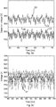
Fig. 5b is an example of the smoothing capacitor voltage when all diodes are healthy, in the presence of a diode short circuit fault, and an open diode fault; and -
Fig. 5c is an example of a smoothing capacitor voltage when the smoothing capacitor is healthy and when the smoothing capacitor has a degraded capacitance. - The inventive concept will now be described more fully hereinafter with reference to the accompanying drawings, in which exemplifying embodiments are shown. The inventive concept may, however, be embodied in many different forms and should not be construed as limited to the embodiments set forth herein; rather, these embodiments are provided by way of example so that this disclosure will be thorough and complete, and will fully convey the scope of the inventive concept to those skilled in the art. Like numbers refer to like elements throughout the description.
-
Fig. 1 shows a cross-sectional view of a portion of an example of an exciterlesssynchronous machine 1. The exemplified exciterlesssynchronous machine 1 is a rotating type of synchronous machine. The exciterlesssynchronous machine 1 comprises astator 3 and arotor 5. Thestator 3 is configured to receive therotor 5. Therotor 5 is configured to rotate relative to thestator 3. - Alternatively, the inverse configuration is also possible, where the rotor is arranged around the stator, a so-called outer rotor machine.
- The
stator 3 is provided with a plurality ofstator slots 3a. In particular, thestator 3 has aninner perimeter surface 3b which faces therotor 5. Theinner perimeter surface 3b is provided with thestator slots 3a. Thestator 3 further comprises one ormore stator windings 3c arranged in thestator slots 3a. - The exemplified
rotor 5 comprises a plurality ofpoles 5a. InFig. 1 , only one pole is shown. Any two poles arranged along the same radial axis form a pole pair. Each pole pair forms part of an electromagnet. Eachpole 5a comprises a pole shoe 5c. In particular, the radially outermost portion of eachpole 5a is the pole shoe 5c. Each pole shoe 5c is provided with a plurality ofrotor slots 5d arranged one after the other in the tangential direction, along anexternal surface 5e of the pole shoe 5c. Theexternal surface 5e faces theinner perimeter surface 3b of thestator 3. Thestator 3 and therotor 5 are separated by an air gap G. - The
rotor 5 furthermore comprisesexcitation coils 5f, also known as energy harvesting coils. Theexcitation coils 5f are provided in therotor slots 5d. For example, each pole pair may comprise arespective excitation coil 5f arranged in thecorresponding rotor slots 5d of the pole shoes 5c of the pole pair. Theexcitation coils 5f are configured to harvest energy obtained from the slot harmonic in the magnetic field from the stator winding(s) 3c. The slot harmonic is equal to the rotational speed ω times the total number n of stator slots. The rotational speed ω is the grid frequency divided by the number of poles of therotor 5. - The
rotor 5 furthermore comprises a field winding 5b configured to electromagnetically interact with the stator winding(s) 3c. The field winding 5b is wound around thepoles 5a. - With reference to
Fig. 2 , an example of an excitation system 7 is shown. Thesynchronous machine 1 comprises the excitation system 7. The excitation system 7 includes theexcitation coils 5f. The excitation system 7 furthermore includes a plurality ofdiode rectifiers 9 arranged on therotor 5. Eachdiode rectifier 9 is configured to rectify current from arespective excitation coil 5f. Eachdiode rectifier 9 comprises a plurality ofdiodes 11. Thediodes 11 of eachdiode rectifier 9 may be arranged in a diode bridge configuration. - The number of
diode rectifiers 9 may beneficially be selected so that there is redundancy in case one of the diode rectifiers breaks down, in particular if one of the diodes is subjected to an open diode failure. - The excitation system 7 furthermore comprises a
busbar 17 to which all of thediode rectifiers 9 are connected in parallel with each other. - The excitation system 7 comprises a
power converter 15. The power converter is a DC-DC converter. Thepower converter 15 is connected to thebusbar 17. Thepower converter 15 is configured to energise the field winding 5b based on the rectified current fed by thediode rectifiers 9 to thebusbar 17. Thepower converter 15 comprises controllable switches. By controlling the switches, the level of energisation of the field winding 5b may be controlled. The switches may for example be insulated gate bipolar transistors (IGBT). The switches may for example be arranged in an H-bridge configuration. The field winding 5b may be connected between pairs of switches which are switched concurrently. - The excitation system 7 furthermore comprises a smoothing
capacitor 13. The smoothingcapacitor 13 is arranged on therotor 5. The smoothingcapacitor 13 is connected to thebusbar 17. The smoothingcapacitor 13 is connected to the busbar between thediode rectifiers 9 and thepower converter 15. The smoothingcapacitor 13 is furthermore connected to ground. The smoothingcapacitor 13 is configured to smooth the rectifier current obtained from thediode rectifiers 9. In this manner a smoothed current can be obtained and delivered to thepower converter 15. - The excitation system 7 may include a
first sensor 19 configured to detect a first electrical parameter, in particular the rectified current flowing in thebusbar 17. Thefirst sensor 19 may thereby be a current sensor, for example a DC current shunt provided by Thermovolt AB, connected in series with thebusbar 17. - The excitation system 7 may comprise a second sensor (not shown) configured to detect a second electrical parameter, in particular a smoothing capacitor voltage across the smoothing
capacitor 13. The second sensor may thereby be a voltage sensor. - The
synchronous machine 1 furthermore comprises amonitoring system 21 configured to detect a fault condition in the excitation system 7. Themonitoring system 21 is configured to receive current measurements from the current sensor and/or voltage measurements from the voltage sensor and to process these measurements to detect whether a fault condition is present in the excitation system 7 and thus in the exciterlesssynchronous machine 1. - The
monitoring system 21 may be located remotely from the rotor in a stationary position. In this case, therotor 5 may be provided with awireless transmitter 22 configured to transmit the current measurements and/or the voltage measurements to the remotely locatedstationary monitoring system 21. Alternatively, the monitoring system may be installed on the rotor. In this case, processed data concerning fault detection as disclosed herein may be wirelessly transmitted by the monitoring system from the rotor to a stationary base station. - The
monitoring system 21 comprises astorage medium 23 comprising computer code, andprocessing circuitry 25. Themonitoring system 21 is configured to detect whether a fault condition is present in the excitation system 7 when the computer code is executed by theprocessing circuitry 25, as will be described in more detail in the following. - The
processing circuitry 25 may use any combination of one or more of a suitable central processing unit (CPU), multiprocessor, microcontroller, digital signal processor (DSP), application specific integrated circuit (ASIC), field programmable gate arrays (FPGA) etc., capable of executing any herein disclosed operations concerning fault detection in the excitation system 7. - The
storage medium 23 may for example be embodied as a memory, such as a random access memory (RAM), a read-only memory (ROM), an erasable programmable read-only memory (EPROM), or an electrically erasable programmable read-only memory (EEPROM) and more particularly as a non-volatile storage medium of a device in an external memory such as a USB (Universal Serial Bus) memory or a Flash memory, such as a compact Flash memory. -
Fig. 3 is a flowchart of a method of detecting a fault condition in the excitation system 7. The method is performed by themonitoring system 21. - In a step S1 the
monitoring system 21, and in particular theprocessing circuitry 25 obtains at least one of a current measurement made by thefirst sensor 19 and a voltage measurement made by the second sensor. - In a step S2, the
monitoring system 21 determines whether a fault condition is present in the excitation system 7 based on at least one of the current measurement and the voltage measurement. - For example, as shown in
Figs 4a and4b , in case a current measurement is received by themonitoring system 21, in step S2 the current measurement may be transformed to the frequency domain to obtain the spectrum of the current, for example using a Fourier transform or any other suitable frequency transform. Alternatively, a filter such as a bandpass filter may be used to obtain the slot harmonic for analysis thereof, or the current measurement may be filtered by a band notch filter with the cut-off frequency at the slot harmonic with the resulting signal being subtracted from the original current measurement. - In case the slot harmonic fs of the rectified current has a magnitude greater than a first threshold value V1, which is larger than a first reference value R1 indicative of a healthy diode condition, but smaller than a second threshold value V2, i.e. if the slot harmonic has a magnitude within a certain predetermined range, an open diode fault in one of the
diodes 11 of adiode rectifier 9 is detected, as shown by curve C1 inFig. 4b . - In case the slot harmonic fs of the rectified current has a magnitude greater than the second threshold value V2, a diode short circuit fault in one of the
diodes 11 of adiode rectifier 9 is detected, as shown by curve C2 inFig. 4b . - Thus, by means of a current measurement an open diode fault and a diode short circuit fault may be detected.
- In case a voltage measurement is received by the
monitoring system 21, in step S2 the voltage measurement may be processed as follows to detect a fault condition in the excitation system. Also in this case, a transformation to the frequency domain may be performed as shown inFig. 5a using e.g. a Fourier transform, or a filter may be used as described above to obtain the slot harmonic. - In the case of using the voltage measurement, in step S2 it is determined whether a slot harmonic of the smoothing capacitor voltage with a magnitude greater than a third threshold value V3, which is larger than a second reference value R2, is present, and whether also the smoothing capacitor voltage is below a smoothing
capacitor voltage threshold 26 to detect a diode short circuit fault in one of thediodes 11 of thediode rectifiers 9. The latter situation is shown inFig. 5b , where curves C3 and C4 show a smoothing capacitor voltage for a healthy diode and an open diode fault, respectively. Both are above the smoothingcapacitor voltage threshold 26. The curve C5 shows the smoothing capacitor voltage obtained when a diode of adiode rectifier 9 has a diode short circuit fault. It can be seen that the smoothing capacitor voltage has dropped compared to the healthy diode case and the open diode fault and is much lower than in the previously mentioned two cases. In particular, it is lower than the smoothingcapacitor voltage threshold 26. It is preferably the DC component of the smoothing capacitor voltage that is analysed in step S2. - If in step S2 it is determined that the slot harmonic of the smoothing capacitor voltage with a magnitude greater than the third threshold value is present and that the smoothing capacitor voltage is above the smoothing
capacitor voltage threshold 26 an open diode fault of one of thediodes 11 in thediode rectifiers 9 is detected. The smoothing capacitor voltage ripple is mainly at the switching frequency of the switches of thepower converter 15. The smoothing capacitor voltage ripple increases proportionally with the deterioration of the smoothingcapacitor 13. - In step S2 it may also be determined whether the amplitude of the smoothing capacitor voltage varies over a larger range than a
healthy ripple range 27, as shown inFig. 5c , to detect that the smoothing capacitor has a degraded capacitance. The more the smoothing capacitor voltage varies or ripples, the more degraded the capacitance may be. - Thus, using the smoothing capacitor voltage, an open diode fault and a diode short circuit fault may be detected, however using both the slot harmonic and the smoothing capacitor voltage ripple in the time domain. Additionally, capacitor degradation may also be detected based on the ripple range of the capacitor voltage.
- The inventive concept has mainly been described above with reference to a few examples. However, as is readily appreciated by a person skilled in the art, other embodiments than the ones disclosed above are equally possible within the scope of the inventive concept, as defined by the appended claims.
Claims (15)
- A method of detecting a fault condition in an excitation system (7) of an exciterless synchronous machine (1) comprising a stator (3); and a rotor (5) provided with a field winding (5b), wherein the rotor (5) has an excitation system (7) including: excitation coils (sf) configured to harvest energy in a gap (G) between the stator (3) and the rotor (5), diodes (11) forming diode rectifiers (9) configured to rectify current from respective excitation coils (sf) to obtain a rectified current, a smoothing capacitor (13) configured to smooth the rectified current to obtain a smoothed current, and a power converter (15) configured to be fed with the smoothed current and to energise the field winding (5b), wherein the method comprises:obtaining (Si) a measurement of at least one of a first electrical parameter and a second electrical parameter, measured between the diode rectifiers (9) and the power converter (15), anddetermining (S2) whether a fault condition is present in at least one of a diode (11) and the smoothing capacitor (13), wherein the determining of the fault condition in one of the diodes (11) is based on the measurement of the first electrical parameter and/or the second electrical parameter, and wherein the determining of the fault condition of the smoothing capacitor (13) is based on the measurement of the second electrical parameter.
- The method as claimed in claim 1, wherein the determining involves determining whether at least one of the first electrical parameter and the second electrical parameter obtained by measurement deviates from a predetermined range of values.
- The method as claimed in claim 1 or 2, wherein the determining involves analysing the spectrum of at least one of the first electrical parameter and the second electrical parameter obtained by measurement.
- The method as claimed in any of the preceding claims, wherein the first electrical parameter is the rectified current.
- The method as claimed in claim 3 or 4, wherein the determining involves determining whether a slot harmonic (fs) of the rectified current with a magnitude greater than a first reference value (R1) indicative of a healthy diode condition is present to detect an open diode fault, the slot harmonic (fs) being the rotational speed of the synchronous machine (1) times the total number of stator slots (3a).
- The method as claimed in claim 5, wherein the determining involves determining whether a slot harmonic (fs) of the rectified current with a magnitude greater than a second threshold value (V2), which is greater than the first reference value (Ri) and greater than a first threshold value (Vi) indicative of an open diode fault, is present to detect a diode short circuit fault.
- The method as claimed in any of the preceding claims, wherein the second electrical parameter is a smoothing capacitor voltage.
- The method as claimed in claim 7, wherein the determining involves determining whether a slot harmonic (fs) of the smoothing capacitor voltage with a magnitude greater than a third threshold value, which is greater than a second reference value (R2) indicative of a healthy diode condition, is present, and whether a smoothing capacitor voltage is below a smoothing capacitor voltage threshold (26), to detect a diode short circuit fault, the slot harmonic (fs) being the rotational speed of the synchronous machine (1) times the total number of stator slots (3a).
- The method as claimed in claim 7 or 8, wherein the determining involves determining whether a slot harmonic of the smoothing capacitor voltage with a magnitude greater than a third threshold value, which is greater than a second reference value (R2) indicative of a healthy diode condition, is present, and whether a smoothing capacitor voltage is above a smoothing capacitor voltage threshold (26), to detect an open diode fault, the slot harmonic (fs) being the rotational speed of the synchronous machine (1) times the total number of stator slots (3a).
- The method as claimed in any of claims 7-9, wherein the determining involves determining whether the amplitude of the smoothing capacitor voltage varies over a larger range than a healthy ripple range (27) to detect that the smoothing capacitor (13) has a degraded capacitance.
- A computer program comprising computer code which when executed by processing circuitry (25) of a monitoring system (21) causes the monitoring system (21) to perform the steps of the method of any of claims 1-10.
- A monitoring system (21) for detecting a fault condition in an excitation system (7) of an exciterless synchronous machine (1) comprising a stator (3); and a rotor (5) provided with a field winding (5b), wherein the rotor (5) has an excitation system (7) including: excitation coils (sf) configured to harvest energy in a gap (G) between the stator (3) and the rotor (5), diodes (11) forming diode rectifiers (9) configured to rectify current from respective excitation coils (5f) to obtain a rectified current, a smoothing capacitor (13) configured to smooth the rectified current to obtain a smoothed current, and a power converter (15) configured to be fed with the smoothed current and to energise the field winding (5b), wherein the monitoring system (21) comprises:processing circuitry (25), anda storage medium (23) comprising computer code which when executed by the processing circuitry (25) causes the monitoring system (21) to perform the steps of the method as claimed in any of claims 1-11.
- An exciterless synchronous machine comprising:a stator (3),a rotor (3) including:a field winding (5b), andan excitation system (7) including:excitation coils (5f) configured to harvest energy in a gap (G) between the stator (3) and the rotor (5),diodes (11) forming diode rectifiers (9) configured to rectify current from respective excitation coils (5g) to obtain a rectified current,a smoothing capacitor (13) configured to smooth the rectified current to obtain a smoothed current,a power converter (15) configured to be fed with the smoothed current and to energise the field winding (5b), andat least one sensor (19) configured to measure at least one of a first electrical parameter and a second electrical parameter between the diode rectifiers (9) and the power converter (15); anda monitoring system (21) as claimed in claim 12.
- The exciterless synchronous machine (1) as claimed in claim 13, wherein the monitoring system (21) is configured to be remotely arranged with respect to the rotor (5).
- The exciterless synchronous machine (1) as claimed in claim 14, comprising a wireless transmitter (22) configured to be mounted on the rotor (5), wherein the wireless transmitter (22) is configured to wirelessly transmit measurements by the at least one sensor (19) to the monitoring system (21).
Priority Applications (1)
| Application Number | Priority Date | Filing Date | Title |
|---|---|---|---|
| EP18182814.6A EP3595167B1 (en) | 2018-07-11 | 2018-07-11 | Condition monitoring of exciterless synchronous machine |
Applications Claiming Priority (1)
| Application Number | Priority Date | Filing Date | Title |
|---|---|---|---|
| EP18182814.6A EP3595167B1 (en) | 2018-07-11 | 2018-07-11 | Condition monitoring of exciterless synchronous machine |
Publications (2)
| Publication Number | Publication Date |
|---|---|
| EP3595167A1 true EP3595167A1 (en) | 2020-01-15 |
| EP3595167B1 EP3595167B1 (en) | 2021-12-01 |
Family
ID=62916497
Family Applications (1)
| Application Number | Title | Priority Date | Filing Date |
|---|---|---|---|
| EP18182814.6A Not-in-force EP3595167B1 (en) | 2018-07-11 | 2018-07-11 | Condition monitoring of exciterless synchronous machine |
Country Status (1)
| Country | Link |
|---|---|
| EP (1) | EP3595167B1 (en) |
Cited By (3)
| Publication number | Priority date | Publication date | Assignee | Title |
|---|---|---|---|---|
| CN112098838A (en) * | 2020-08-25 | 2020-12-18 | 阳江核电有限公司 | Method and device for fault detection of diode open circuit in polyphase angular brushless excitation system |
| EP3916959A1 (en) * | 2020-05-26 | 2021-12-01 | Tetra Laval Holdings & Finance S.A. | Self-powered sensor unit for food packaging machine |
| EP4302394A4 (en) * | 2021-03-05 | 2025-01-22 | Tau Motors, Inc. | WIRELESS POWER TRANSMISSION IN AN ELECTRICAL MACHINE WITH AC AND DC ROTOR COILS |
Citations (4)
| Publication number | Priority date | Publication date | Assignee | Title |
|---|---|---|---|---|
| US20020053889A1 (en) * | 2000-01-11 | 2002-05-09 | Calman Gold | Exciter and electronic regulator for rotating machinery |
| US20150198655A1 (en) * | 2014-01-16 | 2015-07-16 | Rolls-Royce Plc. | Rectifier diode fault detection in brushless exciters |
| US20160211787A1 (en) | 2015-01-16 | 2016-07-21 | Abb Technology Ag | Systems and methods concerning exciterless synchronous machines |
| EP3312988A1 (en) * | 2016-10-18 | 2018-04-25 | ABB Schweiz AG | A method for detecting a fault in an electrical machine |
-
2018
- 2018-07-11 EP EP18182814.6A patent/EP3595167B1/en not_active Not-in-force
Patent Citations (4)
| Publication number | Priority date | Publication date | Assignee | Title |
|---|---|---|---|---|
| US20020053889A1 (en) * | 2000-01-11 | 2002-05-09 | Calman Gold | Exciter and electronic regulator for rotating machinery |
| US20150198655A1 (en) * | 2014-01-16 | 2015-07-16 | Rolls-Royce Plc. | Rectifier diode fault detection in brushless exciters |
| US20160211787A1 (en) | 2015-01-16 | 2016-07-21 | Abb Technology Ag | Systems and methods concerning exciterless synchronous machines |
| EP3312988A1 (en) * | 2016-10-18 | 2018-04-25 | ABB Schweiz AG | A method for detecting a fault in an electrical machine |
Cited By (6)
| Publication number | Priority date | Publication date | Assignee | Title |
|---|---|---|---|---|
| EP3916959A1 (en) * | 2020-05-26 | 2021-12-01 | Tetra Laval Holdings & Finance S.A. | Self-powered sensor unit for food packaging machine |
| WO2021239612A1 (en) * | 2020-05-26 | 2021-12-02 | Tetra Laval Holdings & Finance S.A. | Self-powered sensor unit for food packaging machine |
| US12431736B2 (en) | 2020-05-26 | 2025-09-30 | Tetra Laval Holdings & Finance S.A. | Self-powered sensor unit for food packaging machine |
| CN112098838A (en) * | 2020-08-25 | 2020-12-18 | 阳江核电有限公司 | Method and device for fault detection of diode open circuit in polyphase angular brushless excitation system |
| CN112098838B (en) * | 2020-08-25 | 2023-05-02 | 阳江核电有限公司 | Method and device for detecting faults of diode open circuit of multiphase angular brushless excitation system |
| EP4302394A4 (en) * | 2021-03-05 | 2025-01-22 | Tau Motors, Inc. | WIRELESS POWER TRANSMISSION IN AN ELECTRICAL MACHINE WITH AC AND DC ROTOR COILS |
Also Published As
| Publication number | Publication date |
|---|---|
| EP3595167B1 (en) | 2021-12-01 |
Similar Documents
| Publication | Publication Date | Title |
|---|---|---|
| US9459320B2 (en) | Fault detection in brushless exciters | |
| CN104364989B (en) | System and method for high resistance grounding fault detect in a power distribution system and protection | |
| EP2908148B1 (en) | Rectifier diode fault detection in brushless exciters | |
| CN102057550B (en) | Method for detecting an error in an induction machine | |
| JP6353694B2 (en) | Deterioration diagnosis system | |
| CN101803175B (en) | Method and apparatus for determining a field current in brushless electrical machines | |
| EP3595167A1 (en) | Condition monitoring of exciterless synchronous machine | |
| EP2077613B1 (en) | Shorted rotating diode detection and protection | |
| US3210603A (en) | Generator protection | |
| WO2018072969A1 (en) | A method for detecting a fault in an electrical machine | |
| US4492999A (en) | Supervisory unit for rotary electrical machinery and apparatus | |
| EP3370335B1 (en) | Current sensing in electric machines | |
| US11513155B2 (en) | Method and a diagnostics device for determining a fault condition in a synchronous motor | |
| EP3236275B1 (en) | Electrical machine comprising a rotor measurement unit for measuring a rotor parameter of the electrical machine | |
| CN210954262U (en) | Analysis device for detecting turn-to-turn short circuit in stator coil of motor and motor | |
| KR101664162B1 (en) | Generator protection apparatus and method | |
| JP6596358B2 (en) | Field winding type synchronous motor | |
| JPS6112469B2 (en) | ||
| JP2020515851A (en) | Electric machine with a rotor measuring unit for measuring rotor parameters of the electric machine | |
| CN120584293A (en) | System and method for detecting electrical unbalance and early winding faults in industrial induction motors | |
| KR20250146908A (en) | Control device, electrical machine, and control method of electrical machine | |
| EP3509208A1 (en) | Method of controlling an field wound synchronous machine | |
| JP6482028B2 (en) | Synchronous motor |
Legal Events
| Date | Code | Title | Description |
|---|---|---|---|
| PUAI | Public reference made under article 153(3) epc to a published international application that has entered the european phase |
Free format text: ORIGINAL CODE: 0009012 |
|
| STAA | Information on the status of an ep patent application or granted ep patent |
Free format text: STATUS: THE APPLICATION HAS BEEN PUBLISHED |
|
| AK | Designated contracting states |
Kind code of ref document: A1 Designated state(s): AL AT BE BG CH CY CZ DE DK EE ES FI FR GB GR HR HU IE IS IT LI LT LU LV MC MK MT NL NO PL PT RO RS SE SI SK SM TR |
|
| AX | Request for extension of the european patent |
Extension state: BA ME |
|
| STAA | Information on the status of an ep patent application or granted ep patent |
Free format text: STATUS: REQUEST FOR EXAMINATION WAS MADE |
|
| 17P | Request for examination filed |
Effective date: 20200702 |
|
| RBV | Designated contracting states (corrected) |
Designated state(s): AL AT BE BG CH CY CZ DE DK EE ES FI FR GB GR HR HU IE IS IT LI LT LU LV MC MK MT NL NO PL PT RO RS SE SI SK SM TR |
|
| REG | Reference to a national code |
Ref country code: DE Ref legal event code: R079 Ref document number: 602018027371 Country of ref document: DE Free format text: PREVIOUS MAIN CLASS: H02P0009300000 Ipc: H02K0019120000 |
|
| GRAP | Despatch of communication of intention to grant a patent |
Free format text: ORIGINAL CODE: EPIDOSNIGR1 |
|
| STAA | Information on the status of an ep patent application or granted ep patent |
Free format text: STATUS: GRANT OF PATENT IS INTENDED |
|
| RIC1 | Information provided on ipc code assigned before grant |
Ipc: H02K 19/12 20060101AFI20210601BHEP Ipc: H02K 19/28 20060101ALI20210601BHEP Ipc: H02K 11/042 20160101ALI20210601BHEP Ipc: H02P 29/024 20160101ALI20210601BHEP Ipc: H02P 9/30 20060101ALI20210601BHEP Ipc: H02P 25/03 20160101ALI20210601BHEP |
|
| INTG | Intention to grant announced |
Effective date: 20210702 |
|
| GRAS | Grant fee paid |
Free format text: ORIGINAL CODE: EPIDOSNIGR3 |
|
| GRAA | (expected) grant |
Free format text: ORIGINAL CODE: 0009210 |
|
| STAA | Information on the status of an ep patent application or granted ep patent |
Free format text: STATUS: THE PATENT HAS BEEN GRANTED |
|
| AK | Designated contracting states |
Kind code of ref document: B1 Designated state(s): AL AT BE BG CH CY CZ DE DK EE ES FI FR GB GR HR HU IE IS IT LI LT LU LV MC MK MT NL NO PL PT RO RS SE SI SK SM TR |
|
| RAP3 | Party data changed (applicant data changed or rights of an application transferred) |
Owner name: ABB SCHWEIZ AG |
|
| REG | Reference to a national code |
Ref country code: GB Ref legal event code: FG4D |
|
| REG | Reference to a national code |
Ref country code: AT Ref legal event code: REF Ref document number: 1452728 Country of ref document: AT Kind code of ref document: T Effective date: 20211215 Ref country code: CH Ref legal event code: EP |
|
| REG | Reference to a national code |
Ref country code: IE Ref legal event code: FG4D |
|
| REG | Reference to a national code |
Ref country code: DE Ref legal event code: R096 Ref document number: 602018027371 Country of ref document: DE |
|
| REG | Reference to a national code |
Ref country code: LT Ref legal event code: MG9D |
|
| REG | Reference to a national code |
Ref country code: NL Ref legal event code: MP Effective date: 20211201 |
|
| REG | Reference to a national code |
Ref country code: AT Ref legal event code: MK05 Ref document number: 1452728 Country of ref document: AT Kind code of ref document: T Effective date: 20211201 |
|
| PG25 | Lapsed in a contracting state [announced via postgrant information from national office to epo] |
Ref country code: RS Free format text: LAPSE BECAUSE OF FAILURE TO SUBMIT A TRANSLATION OF THE DESCRIPTION OR TO PAY THE FEE WITHIN THE PRESCRIBED TIME-LIMIT Effective date: 20211201 Ref country code: LT Free format text: LAPSE BECAUSE OF FAILURE TO SUBMIT A TRANSLATION OF THE DESCRIPTION OR TO PAY THE FEE WITHIN THE PRESCRIBED TIME-LIMIT Effective date: 20211201 Ref country code: FI Free format text: LAPSE BECAUSE OF FAILURE TO SUBMIT A TRANSLATION OF THE DESCRIPTION OR TO PAY THE FEE WITHIN THE PRESCRIBED TIME-LIMIT Effective date: 20211201 Ref country code: BG Free format text: LAPSE BECAUSE OF FAILURE TO SUBMIT A TRANSLATION OF THE DESCRIPTION OR TO PAY THE FEE WITHIN THE PRESCRIBED TIME-LIMIT Effective date: 20220301 Ref country code: AT Free format text: LAPSE BECAUSE OF FAILURE TO SUBMIT A TRANSLATION OF THE DESCRIPTION OR TO PAY THE FEE WITHIN THE PRESCRIBED TIME-LIMIT Effective date: 20211201 |
|
| PG25 | Lapsed in a contracting state [announced via postgrant information from national office to epo] |
Ref country code: SE Free format text: LAPSE BECAUSE OF FAILURE TO SUBMIT A TRANSLATION OF THE DESCRIPTION OR TO PAY THE FEE WITHIN THE PRESCRIBED TIME-LIMIT Effective date: 20211201 Ref country code: PL Free format text: LAPSE BECAUSE OF FAILURE TO SUBMIT A TRANSLATION OF THE DESCRIPTION OR TO PAY THE FEE WITHIN THE PRESCRIBED TIME-LIMIT Effective date: 20211201 Ref country code: NO Free format text: LAPSE BECAUSE OF FAILURE TO SUBMIT A TRANSLATION OF THE DESCRIPTION OR TO PAY THE FEE WITHIN THE PRESCRIBED TIME-LIMIT Effective date: 20220301 Ref country code: LV Free format text: LAPSE BECAUSE OF FAILURE TO SUBMIT A TRANSLATION OF THE DESCRIPTION OR TO PAY THE FEE WITHIN THE PRESCRIBED TIME-LIMIT Effective date: 20211201 Ref country code: HR Free format text: LAPSE BECAUSE OF FAILURE TO SUBMIT A TRANSLATION OF THE DESCRIPTION OR TO PAY THE FEE WITHIN THE PRESCRIBED TIME-LIMIT Effective date: 20211201 Ref country code: GR Free format text: LAPSE BECAUSE OF FAILURE TO SUBMIT A TRANSLATION OF THE DESCRIPTION OR TO PAY THE FEE WITHIN THE PRESCRIBED TIME-LIMIT Effective date: 20220302 Ref country code: ES Free format text: LAPSE BECAUSE OF FAILURE TO SUBMIT A TRANSLATION OF THE DESCRIPTION OR TO PAY THE FEE WITHIN THE PRESCRIBED TIME-LIMIT Effective date: 20211201 |
|
| PG25 | Lapsed in a contracting state [announced via postgrant information from national office to epo] |
Ref country code: NL Free format text: LAPSE BECAUSE OF FAILURE TO SUBMIT A TRANSLATION OF THE DESCRIPTION OR TO PAY THE FEE WITHIN THE PRESCRIBED TIME-LIMIT Effective date: 20211201 |
|
| PG25 | Lapsed in a contracting state [announced via postgrant information from national office to epo] |
Ref country code: SM Free format text: LAPSE BECAUSE OF FAILURE TO SUBMIT A TRANSLATION OF THE DESCRIPTION OR TO PAY THE FEE WITHIN THE PRESCRIBED TIME-LIMIT Effective date: 20211201 Ref country code: SK Free format text: LAPSE BECAUSE OF FAILURE TO SUBMIT A TRANSLATION OF THE DESCRIPTION OR TO PAY THE FEE WITHIN THE PRESCRIBED TIME-LIMIT Effective date: 20211201 Ref country code: RO Free format text: LAPSE BECAUSE OF FAILURE TO SUBMIT A TRANSLATION OF THE DESCRIPTION OR TO PAY THE FEE WITHIN THE PRESCRIBED TIME-LIMIT Effective date: 20211201 Ref country code: PT Free format text: LAPSE BECAUSE OF FAILURE TO SUBMIT A TRANSLATION OF THE DESCRIPTION OR TO PAY THE FEE WITHIN THE PRESCRIBED TIME-LIMIT Effective date: 20220401 Ref country code: EE Free format text: LAPSE BECAUSE OF FAILURE TO SUBMIT A TRANSLATION OF THE DESCRIPTION OR TO PAY THE FEE WITHIN THE PRESCRIBED TIME-LIMIT Effective date: 20211201 Ref country code: CZ Free format text: LAPSE BECAUSE OF FAILURE TO SUBMIT A TRANSLATION OF THE DESCRIPTION OR TO PAY THE FEE WITHIN THE PRESCRIBED TIME-LIMIT Effective date: 20211201 |
|
| REG | Reference to a national code |
Ref country code: DE Ref legal event code: R097 Ref document number: 602018027371 Country of ref document: DE |
|
| PG25 | Lapsed in a contracting state [announced via postgrant information from national office to epo] |
Ref country code: IS Free format text: LAPSE BECAUSE OF FAILURE TO SUBMIT A TRANSLATION OF THE DESCRIPTION OR TO PAY THE FEE WITHIN THE PRESCRIBED TIME-LIMIT Effective date: 20220401 |
|
| PLBE | No opposition filed within time limit |
Free format text: ORIGINAL CODE: 0009261 |
|
| STAA | Information on the status of an ep patent application or granted ep patent |
Free format text: STATUS: NO OPPOSITION FILED WITHIN TIME LIMIT |
|
| PG25 | Lapsed in a contracting state [announced via postgrant information from national office to epo] |
Ref country code: DK Free format text: LAPSE BECAUSE OF FAILURE TO SUBMIT A TRANSLATION OF THE DESCRIPTION OR TO PAY THE FEE WITHIN THE PRESCRIBED TIME-LIMIT Effective date: 20211201 Ref country code: AL Free format text: LAPSE BECAUSE OF FAILURE TO SUBMIT A TRANSLATION OF THE DESCRIPTION OR TO PAY THE FEE WITHIN THE PRESCRIBED TIME-LIMIT Effective date: 20211201 |
|
| 26N | No opposition filed |
Effective date: 20220902 |
|
| PG25 | Lapsed in a contracting state [announced via postgrant information from national office to epo] |
Ref country code: SI Free format text: LAPSE BECAUSE OF FAILURE TO SUBMIT A TRANSLATION OF THE DESCRIPTION OR TO PAY THE FEE WITHIN THE PRESCRIBED TIME-LIMIT Effective date: 20211201 |
|
| REG | Reference to a national code |
Ref country code: DE Ref legal event code: R119 Ref document number: 602018027371 Country of ref document: DE |
|
| PG25 | Lapsed in a contracting state [announced via postgrant information from national office to epo] |
Ref country code: MC Free format text: LAPSE BECAUSE OF FAILURE TO SUBMIT A TRANSLATION OF THE DESCRIPTION OR TO PAY THE FEE WITHIN THE PRESCRIBED TIME-LIMIT Effective date: 20211201 |
|
| REG | Reference to a national code |
Ref country code: CH Ref legal event code: PL |
|
| GBPC | Gb: european patent ceased through non-payment of renewal fee |
Effective date: 20220711 |
|
| REG | Reference to a national code |
Ref country code: BE Ref legal event code: MM Effective date: 20220731 |
|
| PG25 | Lapsed in a contracting state [announced via postgrant information from national office to epo] |
Ref country code: LU Free format text: LAPSE BECAUSE OF NON-PAYMENT OF DUE FEES Effective date: 20220711 Ref country code: LI Free format text: LAPSE BECAUSE OF NON-PAYMENT OF DUE FEES Effective date: 20220731 Ref country code: FR Free format text: LAPSE BECAUSE OF NON-PAYMENT OF DUE FEES Effective date: 20220731 Ref country code: CH Free format text: LAPSE BECAUSE OF NON-PAYMENT OF DUE FEES Effective date: 20220731 |
|
| PG25 | Lapsed in a contracting state [announced via postgrant information from national office to epo] |
Ref country code: IT Free format text: LAPSE BECAUSE OF FAILURE TO SUBMIT A TRANSLATION OF THE DESCRIPTION OR TO PAY THE FEE WITHIN THE PRESCRIBED TIME-LIMIT Effective date: 20211201 Ref country code: GB Free format text: LAPSE BECAUSE OF NON-PAYMENT OF DUE FEES Effective date: 20220711 Ref country code: DE Free format text: LAPSE BECAUSE OF NON-PAYMENT OF DUE FEES Effective date: 20230201 Ref country code: BE Free format text: LAPSE BECAUSE OF NON-PAYMENT OF DUE FEES Effective date: 20220731 |
|
| PG25 | Lapsed in a contracting state [announced via postgrant information from national office to epo] |
Ref country code: IE Free format text: LAPSE BECAUSE OF NON-PAYMENT OF DUE FEES Effective date: 20220711 |
|
| PG25 | Lapsed in a contracting state [announced via postgrant information from national office to epo] |
Ref country code: HU Free format text: LAPSE BECAUSE OF FAILURE TO SUBMIT A TRANSLATION OF THE DESCRIPTION OR TO PAY THE FEE WITHIN THE PRESCRIBED TIME-LIMIT; INVALID AB INITIO Effective date: 20180711 |
|
| PG25 | Lapsed in a contracting state [announced via postgrant information from national office to epo] |
Ref country code: MK Free format text: LAPSE BECAUSE OF FAILURE TO SUBMIT A TRANSLATION OF THE DESCRIPTION OR TO PAY THE FEE WITHIN THE PRESCRIBED TIME-LIMIT Effective date: 20211201 Ref country code: CY Free format text: LAPSE BECAUSE OF FAILURE TO SUBMIT A TRANSLATION OF THE DESCRIPTION OR TO PAY THE FEE WITHIN THE PRESCRIBED TIME-LIMIT Effective date: 20211201 |
|
| PG25 | Lapsed in a contracting state [announced via postgrant information from national office to epo] |
Ref country code: TR Free format text: LAPSE BECAUSE OF FAILURE TO SUBMIT A TRANSLATION OF THE DESCRIPTION OR TO PAY THE FEE WITHIN THE PRESCRIBED TIME-LIMIT Effective date: 20211201 |
|
| PG25 | Lapsed in a contracting state [announced via postgrant information from national office to epo] |
Ref country code: MT Free format text: LAPSE BECAUSE OF FAILURE TO SUBMIT A TRANSLATION OF THE DESCRIPTION OR TO PAY THE FEE WITHIN THE PRESCRIBED TIME-LIMIT Effective date: 20211201 |