EP3595163B1 - Dielectric elastomer power generation system - Google Patents
Dielectric elastomer power generation system Download PDFInfo
- Publication number
- EP3595163B1 EP3595163B1 EP18764391.1A EP18764391A EP3595163B1 EP 3595163 B1 EP3595163 B1 EP 3595163B1 EP 18764391 A EP18764391 A EP 18764391A EP 3595163 B1 EP3595163 B1 EP 3595163B1
- Authority
- EP
- European Patent Office
- Prior art keywords
- power generation
- capacitors
- input
- mode
- output
- Prior art date
- Legal status (The legal status is an assumption and is not a legal conclusion. Google has not performed a legal analysis and makes no representation as to the accuracy of the status listed.)
- Active
Links
Images


Classifications
-
- H—ELECTRICITY
- H02—GENERATION; CONVERSION OR DISTRIBUTION OF ELECTRIC POWER
- H02N—ELECTRIC MACHINES NOT OTHERWISE PROVIDED FOR
- H02N2/00—Electric machines in general using piezoelectric effect, electrostriction or magnetostriction
- H02N2/18—Electric machines in general using piezoelectric effect, electrostriction or magnetostriction producing electrical output from mechanical input, e.g. generators
- H02N2/181—Circuits; Control arrangements or methods
-
- H—ELECTRICITY
- H02—GENERATION; CONVERSION OR DISTRIBUTION OF ELECTRIC POWER
- H02N—ELECTRIC MACHINES NOT OTHERWISE PROVIDED FOR
- H02N11/00—Generators or motors not provided for elsewhere; Alleged perpetua mobilia obtained by electric or magnetic means
- H02N11/002—Generators
-
- H—ELECTRICITY
- H02—GENERATION; CONVERSION OR DISTRIBUTION OF ELECTRIC POWER
- H02J—CIRCUIT ARRANGEMENTS OR SYSTEMS FOR SUPPLYING OR DISTRIBUTING ELECTRIC POWER; SYSTEMS FOR STORING ELECTRIC ENERGY
- H02J7/00—Circuit arrangements for charging or depolarising batteries or for supplying loads from batteries
- H02J7/34—Parallel operation in networks using both storage and other DC sources, e.g. providing buffering
- H02J7/345—Parallel operation in networks using both storage and other DC sources, e.g. providing buffering using capacitors as storage or buffering devices
-
- H02J7/50—
-
- H—ELECTRICITY
- H02—GENERATION; CONVERSION OR DISTRIBUTION OF ELECTRIC POWER
- H02M—APPARATUS FOR CONVERSION BETWEEN AC AND AC, BETWEEN AC AND DC, OR BETWEEN DC AND DC, AND FOR USE WITH MAINS OR SIMILAR POWER SUPPLY SYSTEMS; CONVERSION OF DC OR AC INPUT POWER INTO SURGE OUTPUT POWER; CONTROL OR REGULATION THEREOF
- H02M3/00—Conversion of DC power input into DC power output
- H02M3/02—Conversion of DC power input into DC power output without intermediate conversion into AC
- H02M3/04—Conversion of DC power input into DC power output without intermediate conversion into AC by static converters
- H02M3/06—Conversion of DC power input into DC power output without intermediate conversion into AC by static converters using resistors or capacitors, e.g. potential divider
- H02M3/07—Conversion of DC power input into DC power output without intermediate conversion into AC by static converters using resistors or capacitors, e.g. potential divider using capacitors charged and discharged alternately by semiconductor devices with control electrode, e.g. charge pumps
-
- H—ELECTRICITY
- H10—SEMICONDUCTOR DEVICES; ELECTRIC SOLID-STATE DEVICES NOT OTHERWISE PROVIDED FOR
- H10N—ELECTRIC SOLID-STATE DEVICES NOT OTHERWISE PROVIDED FOR
- H10N30/00—Piezoelectric or electrostrictive devices
- H10N30/80—Constructional details
- H10N30/85—Piezoelectric or electrostrictive active materials
- H10N30/857—Macromolecular compositions
Definitions
- the present invention relates to a dielectric elastomer power generation system.
- Patent Documents 1 and 2 disclose a dielectric elastomer power generation system in which a dielectric elastomer element is used in power generation applications.
- power is generated by converting an external force (dynamic energy) that elongates the dielectric elastomer element into electrical energy.
- Electric power resulting from this power generation is stored in secondary batteries typified by nickel-hydrogen batteries and lithium-ion batteries, for example.
- Power generation using a dielectric elastomer element is performed in cycles each consisting of elongation and contraction of the dielectric elastomer element. This is advantageous in that, even when change in the external force or the like that produces this cycle occurs in comparatively short periods of time, the elongation and contraction of the dielectric elastomer element is capable of conforming to this change. Also, an aspect of power generation with a dielectric elastomer element is that the voltage is comparatively high, reaching several thousand volts, for example. On the other hand, since the abovementioned secondary batteries employ a power storage principle utilizing a chemical reaction, charging requires a comparatively long time. Also, the proper voltage for charging secondary batteries is overwhelmingly low compared with the voltage of power generation by a dielectric elastomer element. Thus, difficulties are encountered in efficiently storing power generated using a dielectric elastomer element in secondary batteries.
- the present invention has been conceived under the abovementioned circumstances, and an object thereof is to provide a dielectric elastomer power generation system capable of storing power more efficiently.
- a dielectric elastomer power generation system provided according to a first aspect of the present invention is defined by claim 1.
- control unit in the output mode, connects the capacitors of a number less than or equal to the input series number and larger than the output series number to each other in parallel.
- a dielectric elastomer power generation system provided according to a second aspect of the present invention is defined by claim 3.
- FIGS. 1 to 3 show a dielectric elastomer power generation system that is based on a first embodiment of the present invention.
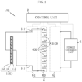
- a dielectric elastomer power generation system A1 of the present embodiment is provided with a power generation unit 1, a control unit 2, an intermediate power storage unit 3, a power storage unit 5, and a switch unit 6.
- the dielectric elastomer power generation system A1 is an apparatus that generates power utilizing an external force.
- the specific configuration of the source that produces the external force is not particularly limited, and sources that produce natural energy typified by ocean waves and sources that produce bioenergy such as the human body can be utilized as appropriate.
- FIG. 1 is a system configuration diagram schematically showing the dielectric elastomer power generation system A1.
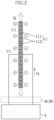
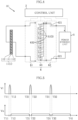
- FIGS. 2 and 3 are diagrams schematically showing the power generation principle of a dielectric elastomer power generation element 11 of the dielectric elastomer power generation system A1.
- the power generation unit 1 is for converting mechanical energy into electrical energy in the dielectric elastomer power generation system A1.
- the power generation unit 1 is provided with the dielectric elastomer power generation element 11. Note that FIGS. 1 to 3 schematically show the dielectric elastomer power generation element 11.
- the dielectric elastomer power generation element 11 has a dielectric elastomer layer 111 and a pair of electrode layers 112.
- components such as a structural member for transmitting the input external force to the dielectric elastomer power generation element 11 and a tension maintaining mechanism for causing tension that is utilized in realizing a power generation operation to be produced in the dielectric elastomer power generation element 11 may be provided as appropriate, in addition to the dielectric elastomer power generation element 11.
- the dielectric elastomer layer 111 is required to be elastically deformable and have high insulation strength.
- the material of such a dielectric elastomer layer 111 is not particularly limited, a silicone elastomer and an acrylic elastomer, for example, are given as preferred examples.
- the pair of electrode layers 112 sandwich the dielectric elastomer layer 111, and are parts to which an initial electric charge is provided and where the output voltage occurs.
- the electrode layers 112 have conductivity, and are formed using an elastically deformable material that can conform to the elastic deformation of the dielectric elastomer layer 111.
- a material obtained by mixing an elastically deformable main material with a filler that provides conductivity is given as an example of such a material.
- Carbon nanotubes, for example, are given as a preferred example of the filler.
- the dielectric elastomer power generation element 11 in a state where an external force or a constraint from outside is not being received and a voltage is not being applied to the pair of electrode layers 112, is in a natural length state in which elongation and contraction does not occur spontaneously, and, in the case where an external force is applied, elastic deformation of the dielectric elastomer layer 111 is allowed.
- the control unit 2 controls application of an initial voltage to the pair of electrode layers 112 of the dielectric elastomer power generation element 11 and input of output power from the pair of electrode layers 112 to the intermediate power storage unit 3 and the power storage unit 5. Also, the control unit 2 performs switch control of the switch unit 6 at the time of this application and input.
- a control unit 2 includes, for example, a power source unit that produces the initial electric charge, a transformation unit that achieve functions such as performing transformation to a voltage suitable for utilization of output power, and a CPU that controls the power source unit and the transformation unit.
- the intermediate power storage unit 3 is for temporarily storing the power generated by the power generation unit 1.
- the intermediate power storage unit 3 includes a plurality of capacitors 31.
- the plurality of capacitors 31 are intended to be connected to each other in series or in parallel by the switch unit 6, at the time of temporary power storage and output to the power storage unit 5 which will be described later.
- the specific configuration of such a plurality of capacitors 31 is changeable as appropriate depending on the configuration of the switch unit 6. In the example illustrated in FIG. 1 , a configuration is adopted in which the plurality of capacitors 31 are disposed separately to each other, and the state in which the capacitors 31 are connected to each other is set by the switch unit 6.
- the specific type of the capacitors 31 is not particularly limited, and various types of capacitors such as electric double layer capacitors, ceramic capacitors and electrolytic capacitors can be employed.
- the number of capacitors 31 included in the intermediate power storage unit 3 is eight. In this case, the specific number referred to in the present invention is eight.
- the plurality of capacitors 31 may be distinguished as capacitors 311 to 318 for convenience of description. Note that, in the present embodiment, an example using capacitors 311 to 318 of uniform capacitance is shown, but capacitors having different capacitances may be combined, and any configuration thereof is possible.
- the number of capacitors 31 is also not limited to eight.
- the power storage unit 5 receives input of the power that is temporarily stored in the intermediate power storage unit 3, and is the final power storage means in the dielectric elastomer power generation system A1.
- the configuration of the power storage unit 5 is not particularly limited, and need only be provided with a power storage capacity capable of appropriately storing the power that is generated by the power generation unit 1.
- a nickel-hydrogen battery or a lithium-ion battery, for example, is given as a so-called secondary battery constituting the power storage unit 5.
- the power storage unit 5 may be provided with a step-down circuit that lowers the input voltage to a voltage suitable for the secondary battery.
- the switch unit 6 is for switching the connection state of the intermediate power storage unit 3 with the power generation unit 1 and the power storage unit 5, and the connection state of the plurality of capacitors 31.
- the specific configuration of the switch unit 6 is not particularly limited, and the switch unit 6 may be constituted by a wiring circuit including the required number of switch components, or may be constituted by an electronic module typified by a so-called switching element.
- the switch unit 6 is schematically shown, as a convenience for describing the functions thereof.
- the switch unit 6 consists of an input-side switch unit 61, an output-side switch unit 62, and an intermediate switch unit 63.
- the input-side switch unit 61 is a part connecting the power generation unit 1 and the intermediate power storage unit 3.
- the output-side switch unit 62 is a part connecting the intermediate power storage unit 3 and the power storage unit 5.
- the intermediate switch unit 63 is a part connecting the plurality of capacitors 31 in a predetermined connection state.
- the input-side switch unit 61, the output-side switch unit 62 and the intermediate switch unit 63 execute switching operations according to a command of the control unit 2.
- a configuration may be adopted in which the control unit 2 and the switch unit 6 are constructed as an integrated component.
- the intermediate power storage unit 3 and the intermediate switch unit 63 may be constituted as an integrated package unit.
- the input-side switch unit 61 disconnects and connects the power generation unit 1 and the intermediate power storage unit 3, according to a command of the control unit 2.
- the input-side switch unit 61 internally generates an input path 611, for example, in the case of connecting the power generation unit 1 and the intermediate power storage unit 3.
- the input path 611 is for connecting an output terminal of the power generation unit 1 and any terminal of the intermediate switch unit 63.
- the output-side switch unit 62 disconnects and connects the intermediate switch unit 63 and the power storage unit 5, according to a command of the control unit 2.
- FIG. 1 shows a state where the output-side switch unit 62 is not connecting the intermediate switch unit 63 and the power storage unit 5.
- the output-side switch unit 62 internally generates an output path 621 shown in FIG. 4 , for example, in the case of connecting the intermediate switch unit 63 and the power storage unit 5.
- the output path 621 is for connecting any terminal of the intermediate switch unit 63 and an input terminal of the power storage unit 5.
- the intermediate switch unit 63 is for selecting any number of capacitors 31 among the plurality of capacitors 31 of the intermediate power storage unit 3, and connecting these capacitors 31 in any connection state, according to a command of the control unit 2.
- the intermediate switch unit 63 internally generates an intermediate path 631 that connects the capacitors 311 to 318 to each other in series.
- FIGS. 2 and 3 show the principle of power generation in the dielectric elastomer power generation element 11.
- the dielectric elastomer power generation element 11 is in a state of being connectable to the intermediate power storage unit 3 via the input-side switch unit 61 of the switch unit 6.
- an external force acting downward in the diagram is applied to the dielectric elastomer power generation element 11.
- the dielectric elastomer layer 111 of the dielectric elastomer power generation element 11 elongates in the up-down direction in the diagram.
- the area of the dielectric elastomer layer 111 thereby increases and the thickness decreases.
- the pair of electrode layers 112 conform to the dielectric elastomer layer 111, and increase in area.
- a capacitance C1 thereof has increased compared with before the external force is applied.
- the initial voltage is applied to the dielectric elastomer power generation element 11 in this state. Specifically, by applying a voltage V1 to the dielectric elastomer power generation element 11 having the capacitance C1, flow of a current Iq occurs, and an electric charge Q is imparted.
- This application may be realized by applying a voltage from a power source unit built into the control unit 2, or a voltage may be applied utilizing the intermediate power storage unit 3 in a power storage state. In FIG. 2 , the case where a voltage is applied from the intermediate power storage unit 3 is shown for convenience.
- FIG. 3 shows a state where the dielectric elastomer power generation element 11 has contracted from the state shown in FIG. 2 , due to the external force weakening or becoming zero after the state shown in FIG. 2 .
- the area of the dielectric elastomer layer 111 decreases and the thickness increases.
- the pair of electrode layers 112 conform to the dielectric elastomer layer 111, and decrease in area.
- a capacitance C2 thereof has decreased to lower than the abovementioned capacitance C1.
- the electric charge Q stored in the pair of electrode layers 112 is constant.
- the ratio of the voltage V2 and the voltage V1 is in an inverse proportional relationship with the ratio of the capacitance C2 and the capacitance C1, and the voltage V2 is high compared to the voltage V1. Accordingly, an output current Iw is received from the pair of electrode layers 112 by the intermediate power storage unit 3 at the voltage V2 that is higher than the voltage V1. Output power exceeding the power required in application of the initial voltage is thereby obtained. Power generation in the dielectric elastomer power generation element 11 is as described above.
- FIG. 1 shows a state where power generation is being performed in the power generation unit 1 of the dielectric elastomer power generation system A1.
- the intermediate switch unit 63 connects the eight capacitors 311 to 318 to each other in series, by generating the intermediate path 631, according to a command of the control unit 2.
- the number of series capacitors 31 that are connected to each other by the intermediate switch unit 63 of the switch unit 6 in an input mode is defined as an input series number.
- the input series number is less than or equal to the abovementioned specific number, and, in the present embodiment, the input series number is eight, and is the same number as the specific number.
- the input-side switch unit 61 of the switch unit 6 is connecting the power generation unit 1 and the intermediate switch unit 63.
- the eight capacitors 311 to 318 connected in series to each other are connected to the power generation unit 1.
- the output-side switch unit 62 is not connecting the intermediate switch unit 63 and the power storage unit 5.
- this mode is defined as the input mode, in which power from the power generation unit 1 is input to the intermediate power storage unit 3.
- the specific number and the input series number are not limited to being the same number, and the input series number may be smaller than the specific number.
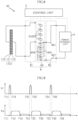
- the horizontal axis is a time axis and the vertical axis is the input voltage Vi to the intermediate power storage unit 3.
- the input voltage Vi corresponds to the difference between the abovementioned voltages V2 and V1.
- the switch unit 6 is in the input mode, according to a command of the control unit 2. Due to the elongation and contraction of the dielectric elastomer power generation element 11, the input voltage Vi increases, and power is input to the intermediate power storage unit 3 according to this voltage.
- the capacitors 311 to 318 are connected to the power generation unit 1 in the input mode. Thus, power is input at the input voltage Vi to the capacitors 311 to 318 that are connected to each other in series. That is, one eighth voltage of the input voltage Vi will be applied to each of the capacitors 311 to 318.
- this mode is defined as an output mode, in which power is output from the intermediate power storage unit 3 to the power storage unit 5.
- switching between the input mode and the output mode can be performed at any timing, and is judged by the control unit 2 using all sorts of judgment criteria.
- switching from the input mode to the output mode may be performed in the case where the input voltage Vi is zero or a value approaching zero.
- switching from the input mode to the output mode may be performed in the case where the dielectric elastomer power generation element 11 is not significantly elongating and contracting, using a sensor (not shown) that detects the elongation and contraction state of the dielectric elastomer power generation element 11.
- an intermediate path 632 is generated within the intermediate switch unit 63, according to a command of the control unit 2, and the eight capacitors 311 to 318 are connected to each other in parallel. These capacitors 311 to 318 are then connected to the power storage unit 5 by the output path 621 of the output-side switch unit 62.
- the number of series capacitors 31 connected to each other by the intermediate switch unit 63 of the switch unit 6 in the output mode is defined as an output series number.
- the output series number is a number less than the input series number, and, in the illustrated example, the output series number is one.
- the power of the capacitors 311 to 318 is output to the power storage unit 5 from times T12 to T21, which is a longer period of time than times T11 to T12.
- an output voltage Vo is a lower voltage than the input voltage Vi, and, in the present embodiment, is one eighth of the input voltage Vi.
- the period of time from times T12 to T21 depends on the time required for the power stored in the capacitors 311 to 318 to be stored in the power storage unit 5.
- the output mode is completed. This completion is judged by the control unit 2 monitoring the electric charge state of the capacitors 311 to 318, for example.
- the power generated by the power generation unit 1 from times T11 to T12 is stored in the power storage unit 5 via the intermediate power storage unit 3, completing one cycle of power generation and power storage. Thereafter, in correspondence with the next power generation in the dielectric elastomer power generation element 11, the control unit 2 switches the switch unit 6 to the input mode.
- FIG. 5 shows the case where the next input mode is started when the output mode is completed at time T21, but an operation example is possible in which a state that is neither the input mode nor the output mode is entered for a predetermined time period after the output mode is completed at time T21.
- the next cycle of power generation and power storage is then executed by the input mode in times T21 to T22 (similar to the input mode in times T11 to T12) and the output mode in times T22 to T31 (similar to the output mode in times T12 to T21), and, furthermore, the next cycle of power generation and power storage thereafter is executed by the input mode in times T31 to T32 (similar to the input mode in times T11 to T12) and the output mode in times T32 to T41 (similar to the output mode in times T12 to T21).
- power generated by the power generation unit 1 is output to the power storage unit 5 after first being stored by the intermediate power storage unit 3. Since power storage of the intermediate power storage unit 3 using the capacitors 31 does not involve a chemical reaction or the like, the power generated by the power generation unit 1 can be quickly stored. Also, the output series number in the output mode in which power is output from the intermediate power storage unit 3 to the power storage unit 5 is less than the input series number in the input mode in which power is input from the power generation unit 1 to the intermediate power storage unit 3. Thus, it is possible to reduce the voltage to the power storage unit 5 in the output mode to lower than the voltage to the intermediate power storage unit 3 in the input mode. This is advantageous in performing power storage by the power storage unit 5 at the proper voltage. Accordingly, with the dielectric elastomer power generation system A1, power generated by the power generation unit 1 can be more efficiently stored in the power storage unit 5.
- all eight capacitors 311 to 318 in which power is stored in the input mode are connected to each other in parallel in the output mode, and the output series number is set to one.
- the output voltage Vo shown in FIG. 5 can thereby be reduced to one eighth of the input voltage Vi, this being preferable in efficiently storing power.
- the ratio of the input voltage Vi and the output voltage Vo will be the ratio of the input series number and the output series number.
- FIGS. 6 to 9 show a dielectric elastomer power generation system that is based on a second embodiment of the present invention. Note that, in these diagrams, the same reference signs as the above embodiment are given to elements that are the same as or similar to the above embodiment.
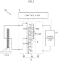
- FIG. 6 shows an input mode of a dielectric elastomer power generation system A2 of the present embodiment.
- the specific number of intermediate power storage unit 3 is eight, similarly to the dielectric elastomer power generation system A1, whereas the input series number is four. That is, the intermediate switch unit 63 generates an intermediate path 631 that connects the four capacitors 311 to 314 to each other in series, according to a command of the control unit 2.
- the capacitors 311 to 314 store power from the power generation unit 1.
- FIG. 7 shows an intermediate mode that is executed according to a command of the control unit 2, after the input mode shown in FIG. 6 .
- the intermediate switch unit 63 generates an intermediate path 632, and connects the four capacitors 311 to 314 to each other in parallel.
- all or some number of the plurality of the capacitors 31 in which power is stored in the input mode are connected such that the series number is an intermediate output series number which is a smaller than the input series number.
- all four capacitors 311 to 314 in which power is stored are connected in parallel by the intermediate path 632, and the series number is one. That is, the intermediate output series number is one in this example.
- the stored power is then moved from the capacitors 311 to 314 to the capacitors 315 to 318, by the capacitors 311 to 314 and the capacitors 315 to 318 being connected to each other.
- FIG. 8 shows an output mode that is executed according to a command of the control unit 2, after the intermediate mode shown in FIG. 7 .
- the intermediate switch unit 63 generates an intermediate path 634, according to a command of the control unit 2, and connects the capacitors 315 to 318 in which power is stored in the intermediate mode to each other.
- the capacitors 315 to 318 are connected such that the series number is an output series number which is smaller than the intermediate input series number.
- the four capacitors 315 to 318 are connected to each other in parallel, and the output series number is one.
- the intermediate switch unit 63 is then connected to the power storage unit 5, by the output path 621 of the output-side switch unit 62. The power stored in the capacitors 315 to 318 is thereby stored in the power storage unit 5.
- FIG. 9 is a graph showing the input mode, the intermediate mode and the output mode in the dielectric elastomer power generation system A2. From times T11 to T12, the input mode is executed at the input voltage Vi. Subsequently, the intermediate mode is executed from times T12 to T13. The output voltage Vo from the capacitors 311 to 315 in the intermediate mode is one quarter of the input voltage Vi. Subsequently, the output mode is executed from times T13 to T21. The output voltage Vo from the capacitors 315 to 318 in the output mode is a further one quarter of the output voltage Vo in the intermediate mode, and is 1/16 of the input voltage Vi in the input mode.
- the output voltage Vo in the output mode can be reduced to 1/16 of the input voltage Vi in the input mode in the example shown in FIG. 9 . This is due to the fact that the ratio of the input voltage Vi in the input mode and the output voltage Vo in the output mode will be a ratio obtained by the ratio of the input series number and the intermediate output series number being multiplied by the ratio of the intermediate input series number and the output series number.
- the dielectric elastomer power generation system according to the present invention is not limited to the abovementioned embodiments. Various design changes can be freely made to the specific configuration of respective parts of the dielectric elastomer power generation system according to the invention.
Landscapes
- Engineering & Computer Science (AREA)
- Power Engineering (AREA)
- Physics & Mathematics (AREA)
- Spectroscopy & Molecular Physics (AREA)
- Charge And Discharge Circuits For Batteries Or The Like (AREA)
- General Electrical Machinery Utilizing Piezoelectricity, Electrostriction Or Magnetostriction (AREA)
Description
- The present invention relates to a dielectric elastomer power generation system.
- Development of dielectric elastomer elements having a dielectric elastomer layer and a pair of electrode layers that sandwich the dielectric elastomer layer is ongoing in the respective fields of drive applications and power generation applications.
Patent Documents - Power generation using a dielectric elastomer element is performed in cycles each consisting of elongation and contraction of the dielectric elastomer element. This is advantageous in that, even when change in the external force or the like that produces this cycle occurs in comparatively short periods of time, the elongation and contraction of the dielectric elastomer element is capable of conforming to this change. Also, an aspect of power generation with a dielectric elastomer element is that the voltage is comparatively high, reaching several thousand volts, for example. On the other hand, since the abovementioned secondary batteries employ a power storage principle utilizing a chemical reaction, charging requires a comparatively long time. Also, the proper voltage for charging secondary batteries is overwhelmingly low compared with the voltage of power generation by a dielectric elastomer element. Thus, difficulties are encountered in efficiently storing power generated using a dielectric elastomer element in secondary batteries.
-
- Patent Document 1:
JP 5479659 - Patent Document 2:
JP 5509350 US 2008 / 0218132 A1 andDE 10 2007 060329 A1 . - The present invention has been conceived under the abovementioned circumstances, and an object thereof is to provide a dielectric elastomer power generation system capable of storing power more efficiently.
- A dielectric elastomer power generation system provided according to a first aspect of the present invention is defined by
claim 1. - In a preferred embodiment of the present invention, the control unit, in the output mode, connects the capacitors of a number less than or equal to the input series number and larger than the output series number to each other in parallel.
- A dielectric elastomer power generation system provided according to a second aspect of the present invention is defined by
claim 3. - Other features and advantages of the present invention will become apparent from the detailed description given below with reference to the accompanying drawings.
-
-
FIG. 1 is a system configuration diagram schematically showing a dielectric elastomer power generation system that is based on a first embodiment of the present invention. -
FIG. 2 is a diagram schematically showing the power generation principle of a dielectric elastomer power generation element of the dielectric elastomer power generation system ofFIG. 1 . -
FIG. 3 is a diagram schematically showing the power generation principle of the dielectric elastomer power generation element of the dielectric elastomer power generation system ofFIG. 1 . -
FIG. 4 is a system configuration diagram schematically showing the dielectric elastomer power generation system ofFIG. 1 . -
FIG. 5 is a graph showing states of power generation by the dielectric elastomer power generation system ofFIG. 1 . -
FIG. 6 is a system configuration diagram schematically showing a dielectric elastomer power generation system based on a second embodiment of the present invention. -
FIG. 7 is a system configuration diagram schematically showing the dielectric elastomer power generation system ofFIG. 6 . -
FIG. 8 is a system configuration diagram schematically showing the dielectric elastomer power generation system ofFIG. 6 . -
FIG. 9 is a graph showing states of power generation by the dielectric elastomer power generation system ofFIG. 6 . - Hereinafter, preferred embodiments of the present invention will be specifically described, with reference to the drawings.
-
FIGS. 1 to 3 show a dielectric elastomer power generation system that is based on a first embodiment of the present invention. A dielectric elastomer power generation system A1 of the present embodiment is provided with apower generation unit 1, acontrol unit 2, an intermediatepower storage unit 3, apower storage unit 5, and aswitch unit 6. The dielectric elastomer power generation system A1 is an apparatus that generates power utilizing an external force. The specific configuration of the source that produces the external force is not particularly limited, and sources that produce natural energy typified by ocean waves and sources that produce bioenergy such as the human body can be utilized as appropriate. -
FIG. 1 is a system configuration diagram schematically showing the dielectric elastomer power generation system A1.FIGS. 2 and3 are diagrams schematically showing the power generation principle of a dielectric elastomerpower generation element 11 of the dielectric elastomer power generation system A1. - The
power generation unit 1 is for converting mechanical energy into electrical energy in the dielectric elastomer power generation system A1. Thepower generation unit 1 is provided with the dielectric elastomerpower generation element 11. Note thatFIGS. 1 to 3 schematically show the dielectric elastomerpower generation element 11. The dielectric elastomerpower generation element 11 has adielectric elastomer layer 111 and a pair ofelectrode layers 112. Note that, in thepower generation unit 1, components (all omitted in the drawings) such as a structural member for transmitting the input external force to the dielectric elastomerpower generation element 11 and a tension maintaining mechanism for causing tension that is utilized in realizing a power generation operation to be produced in the dielectric elastomerpower generation element 11 may be provided as appropriate, in addition to the dielectric elastomerpower generation element 11. - The
dielectric elastomer layer 111 is required to be elastically deformable and have high insulation strength. Although the material of such adielectric elastomer layer 111 is not particularly limited, a silicone elastomer and an acrylic elastomer, for example, are given as preferred examples. - The pair of
electrode layers 112 sandwich thedielectric elastomer layer 111, and are parts to which an initial electric charge is provided and where the output voltage occurs. Theelectrode layers 112 have conductivity, and are formed using an elastically deformable material that can conform to the elastic deformation of thedielectric elastomer layer 111. A material obtained by mixing an elastically deformable main material with a filler that provides conductivity is given as an example of such a material. Carbon nanotubes, for example, are given as a preferred example of the filler. - The dielectric elastomer
power generation element 11, in a state where an external force or a constraint from outside is not being received and a voltage is not being applied to the pair ofelectrode layers 112, is in a natural length state in which elongation and contraction does not occur spontaneously, and, in the case where an external force is applied, elastic deformation of thedielectric elastomer layer 111 is allowed. - The
control unit 2 controls application of an initial voltage to the pair ofelectrode layers 112 of the dielectric elastomerpower generation element 11 and input of output power from the pair ofelectrode layers 112 to the intermediatepower storage unit 3 and thepower storage unit 5. Also, thecontrol unit 2 performs switch control of theswitch unit 6 at the time of this application and input. Such acontrol unit 2 includes, for example, a power source unit that produces the initial electric charge, a transformation unit that achieve functions such as performing transformation to a voltage suitable for utilization of output power, and a CPU that controls the power source unit and the transformation unit. - The intermediate
power storage unit 3 is for temporarily storing the power generated by thepower generation unit 1. The intermediatepower storage unit 3 includes a plurality ofcapacitors 31. The plurality ofcapacitors 31 are intended to be connected to each other in series or in parallel by theswitch unit 6, at the time of temporary power storage and output to thepower storage unit 5 which will be described later. The specific configuration of such a plurality ofcapacitors 31 is changeable as appropriate depending on the configuration of theswitch unit 6. In the example illustrated inFIG. 1 , a configuration is adopted in which the plurality ofcapacitors 31 are disposed separately to each other, and the state in which thecapacitors 31 are connected to each other is set by theswitch unit 6. The specific type of thecapacitors 31 is not particularly limited, and various types of capacitors such as electric double layer capacitors, ceramic capacitors and electrolytic capacitors can be employed. - In the present embodiment, the number of
capacitors 31 included in the intermediatepower storage unit 3 is eight. In this case, the specific number referred to in the present invention is eight. Below, the plurality ofcapacitors 31 may be distinguished ascapacitors 311 to 318 for convenience of description. Note that, in the present embodiment, anexample using capacitors 311 to 318 of uniform capacitance is shown, but capacitors having different capacitances may be combined, and any configuration thereof is possible. The number ofcapacitors 31 is also not limited to eight. - The
power storage unit 5 receives input of the power that is temporarily stored in the intermediatepower storage unit 3, and is the final power storage means in the dielectric elastomer power generation system A1. The configuration of thepower storage unit 5 is not particularly limited, and need only be provided with a power storage capacity capable of appropriately storing the power that is generated by thepower generation unit 1. A nickel-hydrogen battery or a lithium-ion battery, for example, is given as a so-called secondary battery constituting thepower storage unit 5. Also, thepower storage unit 5 may be provided with a step-down circuit that lowers the input voltage to a voltage suitable for the secondary battery. - The
switch unit 6 is for switching the connection state of the intermediatepower storage unit 3 with thepower generation unit 1 and thepower storage unit 5, and the connection state of the plurality ofcapacitors 31. The specific configuration of theswitch unit 6 is not particularly limited, and theswitch unit 6 may be constituted by a wiring circuit including the required number of switch components, or may be constituted by an electronic module typified by a so-called switching element. InFIG. 1 , theswitch unit 6 is schematically shown, as a convenience for describing the functions thereof. In the present embodiment, theswitch unit 6 consists of an input-side switch unit 61, an output-side switch unit 62, and anintermediate switch unit 63. The input-side switch unit 61 is a part connecting thepower generation unit 1 and the intermediatepower storage unit 3. The output-side switch unit 62 is a part connecting the intermediatepower storage unit 3 and thepower storage unit 5. Theintermediate switch unit 63 is a part connecting the plurality ofcapacitors 31 in a predetermined connection state. In the present embodiment, the input-side switch unit 61, the output-side switch unit 62 and theintermediate switch unit 63 execute switching operations according to a command of thecontrol unit 2. Note that a configuration may be adopted in which thecontrol unit 2 and theswitch unit 6 are constructed as an integrated component. Alternatively, the intermediatepower storage unit 3 and theintermediate switch unit 63 may be constituted as an integrated package unit. - The input-
side switch unit 61 disconnects and connects thepower generation unit 1 and the intermediatepower storage unit 3, according to a command of thecontrol unit 2. The input-side switch unit 61 internally generates aninput path 611, for example, in the case of connecting thepower generation unit 1 and the intermediatepower storage unit 3. Theinput path 611 is for connecting an output terminal of thepower generation unit 1 and any terminal of theintermediate switch unit 63. - The output-
side switch unit 62 disconnects and connects theintermediate switch unit 63 and thepower storage unit 5, according to a command of thecontrol unit 2.FIG. 1 shows a state where the output-side switch unit 62 is not connecting theintermediate switch unit 63 and thepower storage unit 5. Also, the output-side switch unit 62 internally generates anoutput path 621 shown inFIG. 4 , for example, in the case of connecting theintermediate switch unit 63 and thepower storage unit 5. Theoutput path 621 is for connecting any terminal of theintermediate switch unit 63 and an input terminal of thepower storage unit 5. - The
intermediate switch unit 63 is for selecting any number ofcapacitors 31 among the plurality ofcapacitors 31 of the intermediatepower storage unit 3, and connecting thesecapacitors 31 in any connection state, according to a command of thecontrol unit 2. In the example shown inFIG. 1 , theintermediate switch unit 63 internally generates anintermediate path 631 that connects thecapacitors 311 to 318 to each other in series. -
FIGS. 2 and3 show the principle of power generation in the dielectric elastomerpower generation element 11. The dielectric elastomerpower generation element 11 is in a state of being connectable to the intermediatepower storage unit 3 via the input-side switch unit 61 of theswitch unit 6. InFIG. 2 , an external force acting downward in the diagram is applied to the dielectric elastomerpower generation element 11. Thus, thedielectric elastomer layer 111 of the dielectric elastomerpower generation element 11 elongates in the up-down direction in the diagram. The area of thedielectric elastomer layer 111 thereby increases and the thickness decreases. The pair ofelectrode layers 112 conform to thedielectric elastomer layer 111, and increase in area. In this state, in the case where the dielectric elastomerpower generation element 11 is regarded as a capacitor, a capacitance C1 thereof has increased compared with before the external force is applied. The initial voltage is applied to the dielectric elastomerpower generation element 11 in this state. Specifically, by applying a voltage V1 to the dielectric elastomerpower generation element 11 having the capacitance C1, flow of a current Iq occurs, and an electric charge Q is imparted. This application may be realized by applying a voltage from a power source unit built into thecontrol unit 2, or a voltage may be applied utilizing the intermediatepower storage unit 3 in a power storage state. InFIG. 2 , the case where a voltage is applied from the intermediatepower storage unit 3 is shown for convenience. -
FIG. 3 shows a state where the dielectric elastomerpower generation element 11 has contracted from the state shown inFIG. 2 , due to the external force weakening or becoming zero after the state shown inFIG. 2 . In this state, the area of thedielectric elastomer layer 111 decreases and the thickness increases. The pair ofelectrode layers 112 conform to thedielectric elastomer layer 111, and decrease in area. In this state, in the case where the dielectric elastomerpower generation element 11 is regarded as a capacitor, a capacitance C2 thereof has decreased to lower than the abovementioned capacitance C1. However, the electric charge Q stored in the pair of electrode layers 112 is constant. Thus, the ratio of the voltage V2 and the voltage V1 is in an inverse proportional relationship with the ratio of the capacitance C2 and the capacitance C1, and the voltage V2 is high compared to the voltage V1. Accordingly, an output current Iw is received from the pair ofelectrode layers 112 by the intermediatepower storage unit 3 at the voltage V2 that is higher than the voltage V1. Output power exceeding the power required in application of the initial voltage is thereby obtained. Power generation in the dielectric elastomerpower generation element 11 is as described above. - Next, power generation and power storage operations of the dielectric elastomer power generation system A1 will be described below, with reference to
FIG. 1 andFIGS. 4 to 6 . -
FIG. 1 shows a state where power generation is being performed in thepower generation unit 1 of the dielectric elastomer power generation system A1. In this state, theintermediate switch unit 63 connects the eightcapacitors 311 to 318 to each other in series, by generating theintermediate path 631, according to a command of thecontrol unit 2. In the present invention, the number ofseries capacitors 31 that are connected to each other by theintermediate switch unit 63 of theswitch unit 6 in an input mode is defined as an input series number. The input series number is less than or equal to the abovementioned specific number, and, in the present embodiment, the input series number is eight, and is the same number as the specific number. Also, the input-side switch unit 61 of theswitch unit 6 is connecting thepower generation unit 1 and theintermediate switch unit 63. The eightcapacitors 311 to 318 connected in series to each other are connected to thepower generation unit 1. On the other hand, the output-side switch unit 62 is not connecting theintermediate switch unit 63 and thepower storage unit 5. In the present invention, this mode is defined as the input mode, in which power from thepower generation unit 1 is input to the intermediatepower storage unit 3. Note that the specific number and the input series number are not limited to being the same number, and the input series number may be smaller than the specific number. - When the dielectric elastomer
power generation element 11 of thepower generation unit 1 elongates and contracts in this state, power is generated in the dielectric elastomerpower generation element 11, according to the principle described with reference toFIGS. 2 and3 . - In the graph in the upper part of
FIG. 5 , the horizontal axis is a time axis and the vertical axis is the input voltage Vi to the intermediatepower storage unit 3. The input voltage Vi corresponds to the difference between the abovementioned voltages V2 and V1. At times T11 to T12 that are illustrated, theswitch unit 6 is in the input mode, according to a command of thecontrol unit 2. Due to the elongation and contraction of the dielectric elastomerpower generation element 11, the input voltage Vi increases, and power is input to the intermediatepower storage unit 3 according to this voltage. In the present embodiment, thecapacitors 311 to 318 are connected to thepower generation unit 1 in the input mode. Thus, power is input at the input voltage Vi to thecapacitors 311 to 318 that are connected to each other in series. That is, one eighth voltage of the input voltage Vi will be applied to each of thecapacitors 311 to 318. - Subsequently, according to a command of the
control unit 2, theswitch unit 6, as shown inFIG. 4 , disconnects thepower generation unit 1 and the intermediatepower storage unit 3, and connects the intermediatepower storage unit 3 and thepower storage unit 5. In the present invention, this mode is defined as an output mode, in which power is output from the intermediatepower storage unit 3 to thepower storage unit 5. Note that switching between the input mode and the output mode can be performed at any timing, and is judged by thecontrol unit 2 using all sorts of judgment criteria. According to the invention in one aspect, by monitoring the voltage (input voltage Vi) of power generation by thepower generation unit 1, switching from the input mode to the output mode may be performed in the case where the input voltage Vi is zero or a value approaching zero. Alternatively and according to another aspect of the invention, switching from the input mode to the output mode may be performed in the case where the dielectric elastomerpower generation element 11 is not significantly elongating and contracting, using a sensor (not shown) that detects the elongation and contraction state of the dielectric elastomerpower generation element 11. - In the illustrated example, an
intermediate path 632 is generated within theintermediate switch unit 63, according to a command of thecontrol unit 2, and the eightcapacitors 311 to 318 are connected to each other in parallel. Thesecapacitors 311 to 318 are then connected to thepower storage unit 5 by theoutput path 621 of the output-side switch unit 62. In the present invention, the number ofseries capacitors 31 connected to each other by theintermediate switch unit 63 of theswitch unit 6 in the output mode is defined as an output series number. The output series number is a number less than the input series number, and, in the illustrated example, the output series number is one. As a result of this connection, power stored in thecapacitors 311 to 318 of the intermediatepower storage unit 3 is output to thepower storage unit 5. Note that, as shown inFIG. 5 , in the present embodiment, the power of thecapacitors 311 to 318 is output to thepower storage unit 5 from times T12 to T21, which is a longer period of time than times T11 to T12. Also, an output voltage Vo is a lower voltage than the input voltage Vi, and, in the present embodiment, is one eighth of the input voltage Vi. The period of time from times T12 to T21 depends on the time required for the power stored in thecapacitors 311 to 318 to be stored in thepower storage unit 5. - When the power stored in the
capacitors 311 to 318 is stored thepower storage unit 5, the output mode is completed. This completion is judged by thecontrol unit 2 monitoring the electric charge state of thecapacitors 311 to 318, for example. - As described above, the power generated by the
power generation unit 1 from times T11 to T12 is stored in thepower storage unit 5 via the intermediatepower storage unit 3, completing one cycle of power generation and power storage. Thereafter, in correspondence with the next power generation in the dielectric elastomerpower generation element 11, thecontrol unit 2 switches theswitch unit 6 to the input mode. Note thatFIG. 5 shows the case where the next input mode is started when the output mode is completed at time T21, but an operation example is possible in which a state that is neither the input mode nor the output mode is entered for a predetermined time period after the output mode is completed at time T21. The next cycle of power generation and power storage is then executed by the input mode in times T21 to T22 (similar to the input mode in times T11 to T12) and the output mode in times T22 to T31 (similar to the output mode in times T12 to T21), and, furthermore, the next cycle of power generation and power storage thereafter is executed by the input mode in times T31 to T32 (similar to the input mode in times T11 to T12) and the output mode in times T32 to T41 (similar to the output mode in times T12 to T21). - Next, operation of the dielectric elastomer power generation system A1 will be described.
- According to the present embodiment, power generated by the
power generation unit 1 is output to thepower storage unit 5 after first being stored by the intermediatepower storage unit 3. Since power storage of the intermediatepower storage unit 3 using thecapacitors 31 does not involve a chemical reaction or the like, the power generated by thepower generation unit 1 can be quickly stored. Also, the output series number in the output mode in which power is output from the intermediatepower storage unit 3 to thepower storage unit 5 is less than the input series number in the input mode in which power is input from thepower generation unit 1 to the intermediatepower storage unit 3. Thus, it is possible to reduce the voltage to thepower storage unit 5 in the output mode to lower than the voltage to the intermediatepower storage unit 3 in the input mode. This is advantageous in performing power storage by thepower storage unit 5 at the proper voltage. Accordingly, with the dielectric elastomer power generation system A1, power generated by thepower generation unit 1 can be more efficiently stored in thepower storage unit 5. - Also, in the present embodiment, all eight
capacitors 311 to 318 in which power is stored in the input mode are connected to each other in parallel in the output mode, and the output series number is set to one. The output voltage Vo shown inFIG. 5 can thereby be reduced to one eighth of the input voltage Vi, this being preferable in efficiently storing power. Note that the ratio of the input voltage Vi and the output voltage Vo will be the ratio of the input series number and the output series number. -
FIGS. 6 to 9 show a dielectric elastomer power generation system that is based on a second embodiment of the present invention. Note that, in these diagrams, the same reference signs as the above embodiment are given to elements that are the same as or similar to the above embodiment. -
FIG. 6 shows an input mode of a dielectric elastomer power generation system A2 of the present embodiment. In the present embodiment, the specific number of intermediatepower storage unit 3 is eight, similarly to the dielectric elastomer power generation system A1, whereas the input series number is four. That is, theintermediate switch unit 63 generates anintermediate path 631 that connects the fourcapacitors 311 to 314 to each other in series, according to a command of thecontrol unit 2. Thus, in the illustrated input mode, only thecapacitors 311 to 314 store power from thepower generation unit 1. -
FIG. 7 shows an intermediate mode that is executed according to a command of thecontrol unit 2, after the input mode shown inFIG. 6 . In this intermediate mode, theintermediate switch unit 63 generates anintermediate path 632, and connects the fourcapacitors 311 to 314 to each other in parallel. In the present invention, all or some number of the plurality of thecapacitors 31 in which power is stored in the input mode are connected such that the series number is an intermediate output series number which is a smaller than the input series number. In the illustrated example, all fourcapacitors 311 to 314 in which power is stored are connected in parallel by theintermediate path 632, and the series number is one. That is, the intermediate output series number is one in this example. - Also, the
intermediate switch unit 63 connects thecapacitors 315 to 318 that are different from thecapacitors 311 to 314 in which power is stored in the input mode to each other by anintermediate path 633, according to a command of thecontrol unit 2. In the present invention, thecapacitors 31 are connected such that the input number is an intermediate input series number which is larger than the intermediate output series number. In the illustrated example, the fourcapacitors 315 to 318 are connected to each other in series by theintermediate path 633, and the intermediate input series number is four. - The stored power is then moved from the
capacitors 311 to 314 to thecapacitors 315 to 318, by thecapacitors 311 to 314 and thecapacitors 315 to 318 being connected to each other. -
FIG. 8 shows an output mode that is executed according to a command of thecontrol unit 2, after the intermediate mode shown inFIG. 7 . In this output mode, theintermediate switch unit 63 generates anintermediate path 634, according to a command of thecontrol unit 2, and connects thecapacitors 315 to 318 in which power is stored in the intermediate mode to each other. In this connection, thecapacitors 315 to 318 are connected such that the series number is an output series number which is smaller than the intermediate input series number. In the illustrated example, the fourcapacitors 315 to 318 are connected to each other in parallel, and the output series number is one. Theintermediate switch unit 63 is then connected to thepower storage unit 5, by theoutput path 621 of the output-side switch unit 62. The power stored in thecapacitors 315 to 318 is thereby stored in thepower storage unit 5. -
FIG. 9 is a graph showing the input mode, the intermediate mode and the output mode in the dielectric elastomer power generation system A2. From times T11 to T12, the input mode is executed at the input voltage Vi. Subsequently, the intermediate mode is executed from times T12 to T13. The output voltage Vo from thecapacitors 311 to 315 in the intermediate mode is one quarter of the input voltage Vi. Subsequently, the output mode is executed from times T13 to T21. The output voltage Vo from thecapacitors 315 to 318 in the output mode is a further one quarter of the output voltage Vo in the intermediate mode, and is 1/16 of the input voltage Vi in the input mode. - Similarly, with such an embodiment, power generated by the
power generation unit 1 can be more efficiently stored in thepower storage unit 5. Also, in the present embodiment, by executing the intermediate mode between the input mode and the output mode, the output voltage Vo in the output mode can be reduced to 1/16 of the input voltage Vi in the input mode in the example shown inFIG. 9 . This is due to the fact that the ratio of the input voltage Vi in the input mode and the output voltage Vo in the output mode will be a ratio obtained by the ratio of the input series number and the intermediate output series number being multiplied by the ratio of the intermediate input series number and the output series number. - The dielectric elastomer power generation system according to the present invention is not limited to the abovementioned embodiments. Various design changes can be freely made to the specific configuration of respective parts of the dielectric elastomer power generation system according to the invention.
Claims (4)
- A dielectric elastomer power generation system (A1) comprising:a power generation unit including a dielectric elastomer power generation element (11) having a dielectric elastomer layer (111) and a pair of electrode layers (112) that sandwich the dielectric elastomer layer (111);an intermediate power storage unit (3) including a plurality of capacitors (31) of a specific number and configured to receive input of output power from the power generation unit;a power storage unit (5) configured to receive input of output power from the intermediate power storage unit (3); anda control unit (2) configured to perform setting control by switching a mode between an input mode and an output mode, whereinin the input mode, a first number of the plurality of capacitors (31) of the intermediate power storage unit (3) are connected to the power generation unit such that an input series number of capacitors (31) in series is less than or equal to the specific number, andin the output mode, a second number of the plurality of capacitors (31) are connected to the power storage unit (5) such that an output series number of capacitors (31) in series is smaller than the input series number, characterised in thatthe control unit (2) performs switching between the input mode and the output mode based on monitoring of a voltage of power generation by the power generation unit or detection of an elongation and contraction state of the dielectric elastomer power generation element (11), andthe control unit (5) performs the switching at any timing, using all sorts of judgment criteria.
- The dielectric elastomer power generation system (A1, A2) according to claim 1, wherein the control unit (2), in the output mode, connects capacitors (31) of a number less than or equal to the input series number and larger than the output series number to each other in parallel.
- A dielectric elastomer power generation system (A2) comprising:a power generation unit including a dielectric elastomer power generation element (11) having a dielectric elastomer layer (111) and a pair of electrode layers (112) that sandwich the dielectric elastomer layer;an intermediate power storage unit (3) including a plurality of capacitors (31) of a specific number and configured to receive input of output power from the power generation unit;a power storage unit (5) configured to receive input of output power from the intermediate power storage unit (3); anda control unit (2) configured to perform setting control by switching a mode between an input mode, an intermediate mode and an output mode, whereinin the input mode, a first number of the plurality of capacitors (31) of the intermediate power storage unit are connected to the power generation unit such that an input series number of capacitors (31) in series is less than or equal to the specific number,in the intermediate mode, the plurality of capacitors (31) in the input mode and the power generation unit are disconnected, a secondnumber of the plurality of capacitors (31) connected to the power generation unit in the input mode are connected such that an intermediate output series number of capacitors (31) in series is smaller than the input series number, and a third number of capacitors (31) other than the plurality of capacitors (31) connected to the power generation unit in the input mode, among the plurality of capacitors (31), are connected such that an intermediate input series number of capacitors (31) in series is larger than the intermediate output series number, andpower is output from the plurality of capacitors (31) connected in the intermediate output series number to the plurality of capacitors (31) connected so as to be in the intermediate input series number, andin the output mode, the plurality of capacitors (31) connected in the intermediate input series number are connected to the power storage unit (5) such that an output series number of capacitors (31) is smaller than the intermediate input series number, characterised in thatthe control unit (2) performs switching from the input mode to the intermediate mode and switching from the intermediate mode to the output mode based on monitoring of a voltage of power generation by the power generation unit or detection of an elongation and contraction state of the dielectric elastomer power generation element (111), andthe control unit (2) performs the switching from the input mode to the intermediate mode and the switching from the intermediate mode to the output mode at any timing, using all sorts of judgment criteria.
- The dielectric elastomer power generation system (A2) according to claim 3, wherein the control unit, in the output mode, connects capacitors (31) of a number less than or equal to the input series number and larger than the output series number to each other in parallel.
Applications Claiming Priority (2)
| Application Number | Priority Date | Filing Date | Title |
|---|---|---|---|
| JP2017044829A JP6998116B2 (en) | 2017-03-09 | 2017-03-09 | Dielectric elastomer power generation system |
| PCT/JP2018/006623 WO2018163854A1 (en) | 2017-03-09 | 2018-02-23 | Dielectric elastomer power generation system |
Publications (3)
| Publication Number | Publication Date |
|---|---|
| EP3595163A1 EP3595163A1 (en) | 2020-01-15 |
| EP3595163A4 EP3595163A4 (en) | 2020-12-30 |
| EP3595163B1 true EP3595163B1 (en) | 2024-07-24 |
Family
ID=63448973
Family Applications (1)
| Application Number | Title | Priority Date | Filing Date |
|---|---|---|---|
| EP18764391.1A Active EP3595163B1 (en) | 2017-03-09 | 2018-02-23 | Dielectric elastomer power generation system |
Country Status (4)
| Country | Link |
|---|---|
| US (1) | US11218091B2 (en) |
| EP (1) | EP3595163B1 (en) |
| JP (1) | JP6998116B2 (en) |
| WO (1) | WO2018163854A1 (en) |
Families Citing this family (2)
| Publication number | Priority date | Publication date | Assignee | Title |
|---|---|---|---|---|
| EP3900848A4 (en) * | 2018-12-21 | 2022-07-06 | Zeon Corporation | Dielectric elastomer drive system and dielectric elastomer drive method |
| JPWO2020175257A1 (en) * | 2019-02-28 | 2020-09-03 |
Family Cites Families (9)
| Publication number | Priority date | Publication date | Assignee | Title |
|---|---|---|---|---|
| JPS5245486A (en) * | 1975-10-07 | 1977-04-09 | Matsushita Electronics Corp | Vessel for packing ring material |
| AU2001268027A1 (en) | 2000-02-23 | 2001-09-12 | Sri International | Biologically powered electroactive polymer generators |
| WO2001063738A2 (en) | 2000-02-23 | 2001-08-30 | Sri International | Electroactive polymer thermal electric generators |
| US7977923B2 (en) | 2007-03-09 | 2011-07-12 | Sri International | Circuits for electroactive polymer generators |
| DE202007018842U1 (en) * | 2007-12-14 | 2009-07-02 | Forschungszentrum Karlsruhe Gmbh | Capacitor block made of interconnectable capacitors |
| FR2970826B1 (en) * | 2011-01-24 | 2013-02-22 | Commissariat Energie Atomique | OPTIMIZATION CIRCUIT FOR THE RECOVERY OF VIBRATION ENERGY BY A MECHANICAL / ELECTRICAL CONVERTER |
| FR2987708B1 (en) * | 2012-03-05 | 2023-11-24 | Commissariat Energie Atomique | ELECTROSTATIC DEVICE FOR RECOVERING MECHANICAL ENERGY BY TRIBOELECTRIC EFFECT |
| JP6228481B2 (en) | 2014-02-17 | 2017-11-08 | シチズン時計株式会社 | Step-down charging system |
| RU2718672C2 (en) * | 2015-12-03 | 2020-04-13 | Конинклейке Филипс Н.В. | Energy generation system and method |
-
2017
- 2017-03-09 JP JP2017044829A patent/JP6998116B2/en active Active
-
2018
- 2018-02-23 US US16/487,979 patent/US11218091B2/en not_active Expired - Fee Related
- 2018-02-23 EP EP18764391.1A patent/EP3595163B1/en active Active
- 2018-02-23 WO PCT/JP2018/006623 patent/WO2018163854A1/en not_active Ceased
Also Published As
| Publication number | Publication date |
|---|---|
| US11218091B2 (en) | 2022-01-04 |
| JP2018148763A (en) | 2018-09-20 |
| EP3595163A4 (en) | 2020-12-30 |
| JP6998116B2 (en) | 2022-01-18 |
| WO2018163854A1 (en) | 2018-09-13 |
| US20200252010A1 (en) | 2020-08-06 |
| EP3595163A1 (en) | 2020-01-15 |
Similar Documents
| Publication | Publication Date | Title |
|---|---|---|
| Maroti et al. | A new structure of high voltage gain SEPIC converter for renewable energy applications | |
| Qahouq et al. | Online closed-loop autotuning digital controller for switching power converters | |
| EP3098866B1 (en) | Piezoelectric power generation module and remote controller | |
| JPWO2020031600A1 (en) | Dielectric elastomer power generation system | |
| EP3595163B1 (en) | Dielectric elastomer power generation system | |
| Hoffstadt et al. | Optimization of the energy harvesting control for dielectric elastomer generators | |
| Ram et al. | Ultra-low power solar energy harvester for IoT edge node devices | |
| JP2018019490A (en) | Dielectric elastomer generator | |
| JP2013192371A (en) | Power storage device, charging method, and discharging method | |
| Alzahrani et al. | Chaotic behavior in high-gain interleaved dc-dc converters | |
| US10421364B2 (en) | Vehicle, in particular an electric vehicle or a hybrid vehicle, and method for charging an energy storage cell of a vehicle | |
| Sato et al. | Bidirectional cascaded quasi-Z-source DC-DC converter | |
| RU2558739C1 (en) | Step-down dc voltage converter | |
| AboReada et al. | Design and control of non-isolated, multi-input dc/dc converter for effective energy management | |
| Zarkov et al. | Theoretical and experimental study of interleaved non-inverting buck-boost converter for RES | |
| Lee et al. | A New Chain-Structured Cell-Balancing Circuit with a Coupled-Inductor Based Modules | |
| Abid et al. | Discrete time model of DC-DC buck converter based on the Euler forward difference | |
| Maas et al. | Model-based control of a dual active bridge for bidirectional feeding of deap transducers | |
| Lo et al. | Transferring electrical energy between two dielectric elastomer actuators | |
| US20240348162A1 (en) | Voltage converter | |
| US20220165932A1 (en) | Dielectric elastomer power generation system | |
| Li et al. | A family of high gain hybrid switched capacitor-inductor dc-dc circuits for renewable energy applications | |
| Beck et al. | Capacitive matrix converters | |
| Chu et al. | A Low-stress High-gain Interleaved DC-DC Converter with Self-balancing Capacitor Voltage | |
| Uno | Cascaded switched capacitor converters with selectable intermediate taps for supercapacitor discharger |
Legal Events
| Date | Code | Title | Description |
|---|---|---|---|
| STAA | Information on the status of an ep patent application or granted ep patent |
Free format text: STATUS: THE INTERNATIONAL PUBLICATION HAS BEEN MADE |
|
| PUAI | Public reference made under article 153(3) epc to a published international application that has entered the european phase |
Free format text: ORIGINAL CODE: 0009012 |
|
| STAA | Information on the status of an ep patent application or granted ep patent |
Free format text: STATUS: REQUEST FOR EXAMINATION WAS MADE |
|
| 17P | Request for examination filed |
Effective date: 20191008 |
|
| AK | Designated contracting states |
Kind code of ref document: A1 Designated state(s): AL AT BE BG CH CY CZ DE DK EE ES FI FR GB GR HR HU IE IS IT LI LT LU LV MC MK MT NL NO PL PT RO RS SE SI SK SM TR |
|
| AX | Request for extension of the european patent |
Extension state: BA ME |
|
| DAV | Request for validation of the european patent (deleted) | ||
| DAX | Request for extension of the european patent (deleted) | ||
| A4 | Supplementary search report drawn up and despatched |
Effective date: 20201202 |
|
| RIC1 | Information provided on ipc code assigned before grant |
Ipc: H02M 3/07 20060101ALI20201126BHEP Ipc: H02N 11/00 20060101AFI20201126BHEP Ipc: H01L 41/193 20060101ALI20201126BHEP Ipc: H02N 2/18 20060101ALI20201126BHEP |
|
| REG | Reference to a national code |
Ref country code: DE Ref legal event code: R079 Ref country code: DE Ref legal event code: R079 Ref document number: 602018072196 Country of ref document: DE Free format text: PREVIOUS MAIN CLASS: H02N0011000000 Ipc: H02N0002180000 |
|
| RIC1 | Information provided on ipc code assigned before grant |
Ipc: H10N 30/857 20230101ALI20240112BHEP Ipc: H02M 3/07 20060101ALI20240112BHEP Ipc: H02N 2/18 20060101AFI20240112BHEP |
|
| GRAP | Despatch of communication of intention to grant a patent |
Free format text: ORIGINAL CODE: EPIDOSNIGR1 |
|
| STAA | Information on the status of an ep patent application or granted ep patent |
Free format text: STATUS: GRANT OF PATENT IS INTENDED |
|
| INTG | Intention to grant announced |
Effective date: 20240301 |
|
| GRAS | Grant fee paid |
Free format text: ORIGINAL CODE: EPIDOSNIGR3 |
|
| GRAA | (expected) grant |
Free format text: ORIGINAL CODE: 0009210 |
|
| STAA | Information on the status of an ep patent application or granted ep patent |
Free format text: STATUS: THE PATENT HAS BEEN GRANTED |
|
| P01 | Opt-out of the competence of the unified patent court (upc) registered |
Free format text: CASE NUMBER: APP_35065/2024 Effective date: 20240611 |
|
| AK | Designated contracting states |
Kind code of ref document: B1 Designated state(s): AL AT BE BG CH CY CZ DE DK EE ES FI FR GB GR HR HU IE IS IT LI LT LU LV MC MK MT NL NO PL PT RO RS SE SI SK SM TR |
|
| REG | Reference to a national code |
Ref country code: GB Ref legal event code: FG4D |
|
| REG | Reference to a national code |
Ref country code: CH Ref legal event code: EP |
|
| REG | Reference to a national code |
Ref country code: IE Ref legal event code: FG4D Ref country code: DE Ref legal event code: R096 Ref document number: 602018072196 Country of ref document: DE |
|
| REG | Reference to a national code |
Ref country code: LT Ref legal event code: MG9D |
|
| REG | Reference to a national code |
Ref country code: NL Ref legal event code: MP Effective date: 20240724 |
|
| PG25 | Lapsed in a contracting state [announced via postgrant information from national office to epo] |
Ref country code: PT Free format text: LAPSE BECAUSE OF FAILURE TO SUBMIT A TRANSLATION OF THE DESCRIPTION OR TO PAY THE FEE WITHIN THE PRESCRIBED TIME-LIMIT Effective date: 20241125 |
|
| REG | Reference to a national code |
Ref country code: AT Ref legal event code: MK05 Ref document number: 1707235 Country of ref document: AT Kind code of ref document: T Effective date: 20240724 |
|
| PG25 | Lapsed in a contracting state [announced via postgrant information from national office to epo] |
Ref country code: NL Free format text: LAPSE BECAUSE OF FAILURE TO SUBMIT A TRANSLATION OF THE DESCRIPTION OR TO PAY THE FEE WITHIN THE PRESCRIBED TIME-LIMIT Effective date: 20240724 |
|
| PG25 | Lapsed in a contracting state [announced via postgrant information from national office to epo] |
Ref country code: PT Free format text: LAPSE BECAUSE OF FAILURE TO SUBMIT A TRANSLATION OF THE DESCRIPTION OR TO PAY THE FEE WITHIN THE PRESCRIBED TIME-LIMIT Effective date: 20241125 Ref country code: NL Free format text: LAPSE BECAUSE OF FAILURE TO SUBMIT A TRANSLATION OF THE DESCRIPTION OR TO PAY THE FEE WITHIN THE PRESCRIBED TIME-LIMIT Effective date: 20240724 |
|
| PG25 | Lapsed in a contracting state [announced via postgrant information from national office to epo] |
Ref country code: NO Free format text: LAPSE BECAUSE OF FAILURE TO SUBMIT A TRANSLATION OF THE DESCRIPTION OR TO PAY THE FEE WITHIN THE PRESCRIBED TIME-LIMIT Effective date: 20241024 |
|
| PG25 | Lapsed in a contracting state [announced via postgrant information from national office to epo] |
Ref country code: FI Free format text: LAPSE BECAUSE OF FAILURE TO SUBMIT A TRANSLATION OF THE DESCRIPTION OR TO PAY THE FEE WITHIN THE PRESCRIBED TIME-LIMIT Effective date: 20240724 Ref country code: GR Free format text: LAPSE BECAUSE OF FAILURE TO SUBMIT A TRANSLATION OF THE DESCRIPTION OR TO PAY THE FEE WITHIN THE PRESCRIBED TIME-LIMIT Effective date: 20241025 Ref country code: PL Free format text: LAPSE BECAUSE OF FAILURE TO SUBMIT A TRANSLATION OF THE DESCRIPTION OR TO PAY THE FEE WITHIN THE PRESCRIBED TIME-LIMIT Effective date: 20240724 |
|
| PG25 | Lapsed in a contracting state [announced via postgrant information from national office to epo] |
Ref country code: BG Free format text: LAPSE BECAUSE OF FAILURE TO SUBMIT A TRANSLATION OF THE DESCRIPTION OR TO PAY THE FEE WITHIN THE PRESCRIBED TIME-LIMIT Effective date: 20240724 |
|
| PG25 | Lapsed in a contracting state [announced via postgrant information from national office to epo] |
Ref country code: LV Free format text: LAPSE BECAUSE OF FAILURE TO SUBMIT A TRANSLATION OF THE DESCRIPTION OR TO PAY THE FEE WITHIN THE PRESCRIBED TIME-LIMIT Effective date: 20240724 |
|
| PG25 | Lapsed in a contracting state [announced via postgrant information from national office to epo] |
Ref country code: IS Free format text: LAPSE BECAUSE OF FAILURE TO SUBMIT A TRANSLATION OF THE DESCRIPTION OR TO PAY THE FEE WITHIN THE PRESCRIBED TIME-LIMIT Effective date: 20241124 Ref country code: AT Free format text: LAPSE BECAUSE OF FAILURE TO SUBMIT A TRANSLATION OF THE DESCRIPTION OR TO PAY THE FEE WITHIN THE PRESCRIBED TIME-LIMIT Effective date: 20240724 |
|
| PG25 | Lapsed in a contracting state [announced via postgrant information from national office to epo] |
Ref country code: HR Free format text: LAPSE BECAUSE OF FAILURE TO SUBMIT A TRANSLATION OF THE DESCRIPTION OR TO PAY THE FEE WITHIN THE PRESCRIBED TIME-LIMIT Effective date: 20240724 |
|
| PG25 | Lapsed in a contracting state [announced via postgrant information from national office to epo] |
Ref country code: ES Free format text: LAPSE BECAUSE OF FAILURE TO SUBMIT A TRANSLATION OF THE DESCRIPTION OR TO PAY THE FEE WITHIN THE PRESCRIBED TIME-LIMIT Effective date: 20240724 |
|
| PG25 | Lapsed in a contracting state [announced via postgrant information from national office to epo] |
Ref country code: PL Free format text: LAPSE BECAUSE OF FAILURE TO SUBMIT A TRANSLATION OF THE DESCRIPTION OR TO PAY THE FEE WITHIN THE PRESCRIBED TIME-LIMIT Effective date: 20240724 Ref country code: NO Free format text: LAPSE BECAUSE OF FAILURE TO SUBMIT A TRANSLATION OF THE DESCRIPTION OR TO PAY THE FEE WITHIN THE PRESCRIBED TIME-LIMIT Effective date: 20241024 Ref country code: LV Free format text: LAPSE BECAUSE OF FAILURE TO SUBMIT A TRANSLATION OF THE DESCRIPTION OR TO PAY THE FEE WITHIN THE PRESCRIBED TIME-LIMIT Effective date: 20240724 Ref country code: IS Free format text: LAPSE BECAUSE OF FAILURE TO SUBMIT A TRANSLATION OF THE DESCRIPTION OR TO PAY THE FEE WITHIN THE PRESCRIBED TIME-LIMIT Effective date: 20241124 Ref country code: HR Free format text: LAPSE BECAUSE OF FAILURE TO SUBMIT A TRANSLATION OF THE DESCRIPTION OR TO PAY THE FEE WITHIN THE PRESCRIBED TIME-LIMIT Effective date: 20240724 Ref country code: GR Free format text: LAPSE BECAUSE OF FAILURE TO SUBMIT A TRANSLATION OF THE DESCRIPTION OR TO PAY THE FEE WITHIN THE PRESCRIBED TIME-LIMIT Effective date: 20241025 Ref country code: FI Free format text: LAPSE BECAUSE OF FAILURE TO SUBMIT A TRANSLATION OF THE DESCRIPTION OR TO PAY THE FEE WITHIN THE PRESCRIBED TIME-LIMIT Effective date: 20240724 Ref country code: ES Free format text: LAPSE BECAUSE OF FAILURE TO SUBMIT A TRANSLATION OF THE DESCRIPTION OR TO PAY THE FEE WITHIN THE PRESCRIBED TIME-LIMIT Effective date: 20240724 Ref country code: BG Free format text: LAPSE BECAUSE OF FAILURE TO SUBMIT A TRANSLATION OF THE DESCRIPTION OR TO PAY THE FEE WITHIN THE PRESCRIBED TIME-LIMIT Effective date: 20240724 Ref country code: AT Free format text: LAPSE BECAUSE OF FAILURE TO SUBMIT A TRANSLATION OF THE DESCRIPTION OR TO PAY THE FEE WITHIN THE PRESCRIBED TIME-LIMIT Effective date: 20240724 |
|
| PG25 | Lapsed in a contracting state [announced via postgrant information from national office to epo] |
Ref country code: SM Free format text: LAPSE BECAUSE OF FAILURE TO SUBMIT A TRANSLATION OF THE DESCRIPTION OR TO PAY THE FEE WITHIN THE PRESCRIBED TIME-LIMIT Effective date: 20240724 Ref country code: DK Free format text: LAPSE BECAUSE OF FAILURE TO SUBMIT A TRANSLATION OF THE DESCRIPTION OR TO PAY THE FEE WITHIN THE PRESCRIBED TIME-LIMIT Effective date: 20240724 Ref country code: RO Free format text: LAPSE BECAUSE OF FAILURE TO SUBMIT A TRANSLATION OF THE DESCRIPTION OR TO PAY THE FEE WITHIN THE PRESCRIBED TIME-LIMIT Effective date: 20240724 |
|
| PG25 | Lapsed in a contracting state [announced via postgrant information from national office to epo] |
Ref country code: EE Free format text: LAPSE BECAUSE OF FAILURE TO SUBMIT A TRANSLATION OF THE DESCRIPTION OR TO PAY THE FEE WITHIN THE PRESCRIBED TIME-LIMIT Effective date: 20240724 |
|
| PG25 | Lapsed in a contracting state [announced via postgrant information from national office to epo] |
Ref country code: CZ Free format text: LAPSE BECAUSE OF FAILURE TO SUBMIT A TRANSLATION OF THE DESCRIPTION OR TO PAY THE FEE WITHIN THE PRESCRIBED TIME-LIMIT Effective date: 20240724 |
|
| REG | Reference to a national code |
Ref country code: DE Ref legal event code: R097 Ref document number: 602018072196 Country of ref document: DE |
|
| PG25 | Lapsed in a contracting state [announced via postgrant information from national office to epo] |
Ref country code: SK Free format text: LAPSE BECAUSE OF FAILURE TO SUBMIT A TRANSLATION OF THE DESCRIPTION OR TO PAY THE FEE WITHIN THE PRESCRIBED TIME-LIMIT Effective date: 20240724 Ref country code: IT Free format text: LAPSE BECAUSE OF FAILURE TO SUBMIT A TRANSLATION OF THE DESCRIPTION OR TO PAY THE FEE WITHIN THE PRESCRIBED TIME-LIMIT Effective date: 20240724 |
|
| PLBE | No opposition filed within time limit |
Free format text: ORIGINAL CODE: 0009261 |
|
| STAA | Information on the status of an ep patent application or granted ep patent |
Free format text: STATUS: NO OPPOSITION FILED WITHIN TIME LIMIT |
|
| 26N | No opposition filed |
Effective date: 20250425 |
|
| REG | Reference to a national code |
Ref country code: DE Ref legal event code: R119 Ref document number: 602018072196 Country of ref document: DE |
|
| PG25 | Lapsed in a contracting state [announced via postgrant information from national office to epo] |
Ref country code: SE Free format text: LAPSE BECAUSE OF FAILURE TO SUBMIT A TRANSLATION OF THE DESCRIPTION OR TO PAY THE FEE WITHIN THE PRESCRIBED TIME-LIMIT Effective date: 20240724 |
|
| PG25 | Lapsed in a contracting state [announced via postgrant information from national office to epo] |
Ref country code: MC Free format text: LAPSE BECAUSE OF FAILURE TO SUBMIT A TRANSLATION OF THE DESCRIPTION OR TO PAY THE FEE WITHIN THE PRESCRIBED TIME-LIMIT Effective date: 20240724 |
|
| REG | Reference to a national code |
Ref country code: CH Ref legal event code: PL |
|
| PG25 | Lapsed in a contracting state [announced via postgrant information from national office to epo] |
Ref country code: LU Free format text: LAPSE BECAUSE OF NON-PAYMENT OF DUE FEES Effective date: 20250223 |
|
| PG25 | Lapsed in a contracting state [announced via postgrant information from national office to epo] |
Ref country code: CH Free format text: LAPSE BECAUSE OF NON-PAYMENT OF DUE FEES Effective date: 20250228 |
|
| GBPC | Gb: european patent ceased through non-payment of renewal fee |
Effective date: 20250223 |
|
| REG | Reference to a national code |
Ref country code: BE Ref legal event code: MM Effective date: 20250228 |
|
| PG25 | Lapsed in a contracting state [announced via postgrant information from national office to epo] |
Ref country code: DE Free format text: LAPSE BECAUSE OF NON-PAYMENT OF DUE FEES Effective date: 20250902 |
|
| PG25 | Lapsed in a contracting state [announced via postgrant information from national office to epo] |
Ref country code: GB Free format text: LAPSE BECAUSE OF NON-PAYMENT OF DUE FEES Effective date: 20250223 |
|
| PG25 | Lapsed in a contracting state [announced via postgrant information from national office to epo] |
Ref country code: FR Free format text: LAPSE BECAUSE OF NON-PAYMENT OF DUE FEES Effective date: 20250228 |
|
| PG25 | Lapsed in a contracting state [announced via postgrant information from national office to epo] |
Ref country code: BE Free format text: LAPSE BECAUSE OF NON-PAYMENT OF DUE FEES Effective date: 20250228 |
|
| PG25 | Lapsed in a contracting state [announced via postgrant information from national office to epo] |
Ref country code: IE Free format text: LAPSE BECAUSE OF NON-PAYMENT OF DUE FEES Effective date: 20250223 |